JP2012144271A - Cushioning packaging material - Google Patents
Cushioning packaging material Download PDFInfo
- Publication number
- JP2012144271A JP2012144271A JP2011004075A JP2011004075A JP2012144271A JP 2012144271 A JP2012144271 A JP 2012144271A JP 2011004075 A JP2011004075 A JP 2011004075A JP 2011004075 A JP2011004075 A JP 2011004075A JP 2012144271 A JP2012144271 A JP 2012144271A
- Authority
- JP
- Japan
- Prior art keywords
- packing
- band
- recess
- packing band
- positioning
- Prior art date
- Legal status (The legal status is an assumption and is not a legal conclusion. Google has not performed a legal analysis and makes no representation as to the accuracy of the status listed.)
- Pending
Links
Images
Landscapes
- Buffer Packaging (AREA)
Abstract
【課題】横方向及び高さ方向に配列された梱包品の引き出し作業の作業性を向上させることができる緩衝梱包材を提供する。
【解決手段】端面47には、第1位置決め部61と第2位置決め部62との間において梱包用バンド93が通る領域の一部に凹部63が設けられている。凹部63と第1位置決め部61との間には、梱包用バンド93の内面が当接又は近接する第1平坦面71が介在し、凹部63と第2位置決め部62との間には、梱包用バンド93の内面が当接又は近接する第2平坦面72が介在している。
【選択図】図2The present invention provides a shock-absorbing packing material capable of improving the workability of a pulling-out operation of a packaged product arranged in a lateral direction and a height direction.
A recess 63 is provided in an end surface 47 in a part of a region through which a packing band 93 passes between a first positioning portion 61 and a second positioning portion 62. Between the concave portion 63 and the first positioning portion 61, a first flat surface 71 with which the inner surface of the packing band 93 comes into contact or close is interposed, and between the concave portion 63 and the second positioning portion 62, there is a packaging. A second flat surface 72 with which the inner surface of the band 93 abuts or approaches is interposed.
[Selection] Figure 2
Description
本発明は、空気調和機などの被梱包物を梱包するための緩衝梱包材に関する。 The present invention relates to a buffer packing material for packing an object to be packed such as an air conditioner.
例えば空気調和機などのようにある程度の重量を有する製品を保管したり、輸送したりする際には、その製品は梱包材で梱包される。通常、梱包材としては、製品(被梱包物)の両端部にそれぞれ嵌合される一対の緩衝梱包材(例えば発泡スチロール成型品)が用いられる。そして、製品の周囲には、段ボールやフィルムなどの梱包材がさらに巻き付けられ、これらの梱包材の周囲に帯状の梱包用バンド(樹脂バンド)が巻き付けられて梱包品が完成する(例えば特許文献1)。 For example, when a product having a certain weight, such as an air conditioner, is stored or transported, the product is packed with a packing material. Usually, as a packing material, a pair of buffer packing materials (for example, a polystyrene foam molded product) respectively fitted to both ends of a product (packaged object) are used. A packing material such as cardboard or film is further wound around the product, and a band-shaped packing band (resin band) is wound around the packing material to complete a packaged product (for example, Patent Document 1). ).
前記梱包品は、保管、輸送などの際には、横方向にほとんど隙間なく配列されるとともに、高さ方向にも段積みされて配列される。このような配列状態であっても、製品は、梱包材により梱包されていることによって保管時及び輸送時に加わる荷重や輸送時の衝撃などから保護される。 In the case of storage, transportation, etc., the packaged goods are arranged with almost no gap in the lateral direction and are also stacked and arranged in the height direction. Even in such an arrangement state, the product is protected from a load applied during storage and transportation, an impact during transportation, and the like by being packaged by a packaging material.
しかしながら、特許文献1などの従来の梱包形態の梱包品は、横方向及び高さ方向に隙間なく配列された状態では、例えば最上段に配置されている梱包品の一つを手前に引き出して取り出したいときに作業者が掴むところがないため、例えば作業台にのって、梱包品の底面を両手で持って持ち上げるような作業が必要であった。また、このような作業は、高さ方向の段積み数が多い場合には特に作業効率がわるくなる。 However, a packaged product of a conventional packaging form such as Patent Document 1 is taken out by pulling out, for example, one of the packaged products arranged at the uppermost stage in a state where there is no gap in the horizontal direction and the height direction. Since there is no place for the operator to grab when he wants, for example, it is necessary to lift the bottom of the package with both hands on the work table. In addition, such work is particularly inefficient when the number of stacks in the height direction is large.
そこで、本発明は、かかる点に鑑みてなされたものであり、その目的とするところは、横方向及び高さ方向に配列された梱包品の引き出し作業の作業性を向上させることができる緩衝梱包材を提供することにある。 Therefore, the present invention has been made in view of the above points, and an object of the present invention is to provide a shock-absorbing package capable of improving the workability of a pulling-out operation of a packaged product arranged in the horizontal direction and the height direction. To provide materials.
本発明の緩衝梱包材は、被梱包物(91)における予め定められた一方向(D)の端部に嵌合可能な発泡プラスチック成形体であり、前記一方向(D)に位置する端面(47)と、この端面(47)につながり、互いに対向する一対の縁部(42,43)とを有している。この緩衝梱包材は、前記被梱包物(91)に嵌合された状態で帯状の梱包用バンド(93)を、少なくとも一方の縁部(42)、前記端面(47)及び他方の縁部(43)を通って巻き付け可能である。 The shock-absorbing packing material of the present invention is a foamed plastic molded body that can be fitted to an end in one predetermined direction (D) in the article to be packed (91), and an end face located in the one direction (D) ( 47) and a pair of edges (42, 43) connected to the end face (47) and facing each other. This cushioning packing material has a band-shaped packing band (93) in a state of being fitted to the article to be packed (91), at least one edge (42), the end surface (47) and the other edge ( 43) Can be wound through.
前記一方の縁部(42)には、前記梱包用バンド(93)を位置決めする役割を担い、前記梱包用バンド(93)が配置される第1位置決め部(61)が設けられている。前記他方の縁部(43)には、前記梱包用バンド(93)を位置決めする役割を担い、前記梱包用バンド(93)が配置される第2位置決め部(62)が設けられている。前記端面(47)には、前記第1位置決め部(61)と前記第2位置決め部(62)との間において前記梱包用バンド(93)が通る領域の一部に凹部(63)が設けられている。 The one edge portion (42) is provided with a first positioning portion (61) that plays a role of positioning the packing band (93) and in which the packing band (93) is disposed. The other edge portion (43) is provided with a second positioning portion (62) for positioning the packing band (93) and in which the packing band (93) is disposed. The end face (47) is provided with a recess (63) in a part of a region through which the packing band (93) passes between the first positioning part (61) and the second positioning part (62). ing.
前記凹部(63)と前記第1位置決め部(61)との間には、前記梱包用バンド(93)の内面が当接又は近接する第1平坦面(71)が介在し、前記凹部(63)と前記第2位置決め部(62)との間には、前記梱包用バンド(93)の内面が当接又は近接する第2平坦面(72)が介在している。 Between the concave portion (63) and the first positioning portion (61), a first flat surface (71) with which the inner surface of the packing band (93) abuts or approaches is interposed, and the concave portion (63 ) And the second positioning portion (62), a second flat surface (72) with which the inner surface of the packing band (93) abuts or approaches is interposed.
この構成では、緩衝梱包材の端面(47)には、前記梱包用バンド(93)が通る領域の一部に凹部(63)が設けられている。したがって、梱包用バンド(93)が巻き付けられた梱包品には、梱包用バンド(93)と凹部(63)との間に作業者が指を差し入れ可能な空間が形成される。これにより、複数の梱包品が横方向及び高さ方向に隙間なく配列された状態において、例えば最上段に配置されている梱包品の一つを取り出したいときに、作業者は、梱包用バンド(93)と凹部(63)との間に形成された前記空間に指を差し入れることができ、この差し入れた指によって梱包用バンド(93)を掴み、梱包品を片手で手前に容易に引き出すことができる。また、場合によっては、従来のような作業台も不要になる。したがって、製品の梱包に本構成の緩衝梱包材を用いることにより、梱包品の引き出し作業の作業性が向上する。 In this configuration, the end face (47) of the buffer packing material is provided with a recess (63) in a part of the region through which the packing band (93) passes. Therefore, a space in which an operator can insert a finger is formed between the packing band (93) and the recess (63) in the packaged product around which the packing band (93) is wound. Thus, in a state where a plurality of packed products are arranged without gaps in the horizontal direction and the height direction, for example, when one wants to take out one of the packed products arranged at the uppermost stage, the operator 93) and a finger can be inserted into the space formed between the recess (63), the packing band (93) can be grasped with the inserted finger, and the packaged product can be easily pulled out with one hand. Can do. In some cases, a conventional work table is not required. Therefore, by using the buffer packing material having this configuration for packing the product, the workability of drawing out the packaged product is improved.
しかも、この構成では、凹部(63)と第1位置決め部(61)との間には、梱包用バンド(93)の内面が当接又は近接する第1平坦面(71)が介在し、凹部(63)と第2位置決め部(62)との間には、梱包用バンド(93)の内面が当接又は近接する第2平坦面(72)が介在している。このように端面において梱包用バンド(93)が通る領域のうち、凹部(63)、第1位置決め部(61)及び第2位置決め部(62)以外の領域は、第1平坦面(71)及び第2平坦面(72)によって構成されているので、凹部(63)の両サイド(第1位置決め部(61)側と第2位置決め部(62)側)の領域の肉厚を十分に厚くすることが可能となる。したがって、凹部(63)を設けることに起因する緩衝梱包材の強度低下を抑制することができる。また、梱包用バンド(93)が巻き付けられた状態では、第1平坦面(71)及び第2平坦面(72)には、梱包用バンド(93)が当接又は近接するので、梱包用バンド(93)の巻き付け状態が安定する。 In addition, in this configuration, the first flat surface (71) with which the inner surface of the packing band (93) abuts or approaches is interposed between the recess (63) and the first positioning portion (61), and the recess Between the (63) and the second positioning portion (62), there is a second flat surface (72) with which the inner surface of the packing band (93) abuts or approaches. As described above, the region other than the recess (63), the first positioning portion (61), and the second positioning portion (62) in the region through which the packing band (93) passes on the end surface is the first flat surface (71) and Since it is constituted by the second flat surface (72), the thickness of the regions on both sides (the first positioning portion (61) side and the second positioning portion (62) side) of the concave portion (63) is sufficiently increased. It becomes possible. Therefore, it is possible to suppress a decrease in strength of the buffer packing material due to the provision of the recess (63). Further, in the state where the packing band (93) is wound, the packing band (93) is in contact with or close to the first flat surface (71) and the second flat surface (72). The winding state of (93) is stabilized.
また、前記凹部(63)は、前記梱包用バンド(93)の延びる方向の寸法よりもこれに直交する直交方向の寸法の方が長い細長形状を有し、前記梱包用バンド(93)が巻き付けられたときに前記梱包用バンド(93)に対して前記直交方向の少なくとも一方に前記凹部(63)の一部が露出するように設けられているのが好ましい。 Further, the recess (63) has an elongated shape in which the dimension in the orthogonal direction perpendicular to the dimension in the extending direction of the packing band (93) is longer, and the packing band (93) is wound around It is preferable that a part of the recess (63) is exposed in at least one of the orthogonal directions with respect to the packing band (93).
この構成では、梱包用バンド(93)が巻き付けられた状態において、梱包用バンド(93)に対して前記直交方向の少なくとも一方に凹部(63)の一部が露出するので、作業者は、この露出した領域から梱包用バンド(93)と凹部(63)との間に指を簡単に差し入れることが可能になる。これにより、梱包品の取り出し作業の作業性がより向上する。 In this configuration, in a state where the packing band (93) is wound, a part of the recess (63) is exposed in at least one of the orthogonal directions with respect to the packing band (93). It becomes possible to easily insert a finger between the packing band (93) and the recess (63) from the exposed region. Thereby, workability | operativity of the taking-out operation | work of a packaged item improves more.
また、前記凹部(63)は、前記端面(47)における高さ方向の中央よりも下方に設けられているのが好ましい。 Moreover, it is preferable that the said recessed part (63) is provided below rather than the center of the height direction in the said end surface (47).
この構成では、高さ方向の段積み数が多い場合に特に有効であり、作業者の手が凹部(63)に届きやすくなるので、高い位置にある梱包品の取り出し作業の作業性がより向上する。 This configuration is particularly effective when the number of stacks in the height direction is large, and the operator's hand can easily reach the recess (63), so the workability of taking out the packaged product at a high position is further improved. To do.
また、前記凹部(63)は、前記端面(47)において、前記梱包用バンド(93)の延びる方向に直交する直交方向の一方に偏った位置に設けられており、かつ前記梱包用バンド(93)が巻き付けられたときに前記梱包用バンド(93)に対して前記直交方向の一方に露出する前記凹部(63)の露出領域が前記直交方向の他方に露出する前記凹部(63)の露出領域よりも大きい形態であるのが好ましい。 Further, the recess (63) is provided at a position biased to one end of the end surface (47) in an orthogonal direction orthogonal to the extending direction of the packing band (93), and the packing band (93 ) Is exposed, the exposed region of the recess (63) exposed in one of the orthogonal directions to the packing band (93) is exposed in the other of the orthogonal directions. The larger form is preferred.
この構成では、凹部(63)が端面(47)において、前記直交方向の一方(例えば右側)に偏った位置に設けられている場合に、梱包用バンド(93)に対して前記直交方向の一方(例えば右側)に露出する凹部(63)の露出領域が前記直交方向の他方(例えば左側)に露出する凹部(63)の露出領域よりも大きい。したがって、例えば梱包品の取り出し作業を右手で行う場合には、凹部(63)が端面(47)において右側に偏った位置にあり、かつ右側の露出領域の方が大きいことによって、この右側の露出領域に右手の指を差し入れやすくなる。しかも、端面(47)において右側に偏った位置に巻き付けられた梱包用バンド(93)を右手の指で引っ張る作業は、作業時のバランスがよく、作業者が力を入れやすいなどのメリットがあり、作業効率がさらに向上する。 In this configuration, when the recess (63) is provided on the end surface (47) at a position biased to one of the orthogonal directions (for example, the right side), one of the orthogonal directions relative to the packing band (93) is provided. The exposed area of the recessed part (63) exposed to (for example, the right side) is larger than the exposed area of the recessed part (63) exposed to the other of the orthogonal directions (for example, the left side). Therefore, for example, when taking out the packaged product with the right hand, the concave portion (63) is in a position biased to the right side in the end surface (47), and the right side exposure area is larger, so that the right side exposure is performed. It becomes easier to insert the finger of the right hand into the area. In addition, pulling the packing band (93) wound at a position biased to the right side on the end face (47) with the fingers of the right hand has advantages such as good balance during work and easy effort by the operator. , Work efficiency is further improved.
本発明によれば、横方向及び高さ方向に配列された梱包品の引き出し作業の作業性を向上させることができる。 ADVANTAGE OF THE INVENTION According to this invention, workability | operativity of the extraction | drawer operation | work of the packaged goods arranged in the horizontal direction and the height direction can be improved.
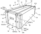
以下、本発明の一実施形態に係る緩衝梱包材11について図面を参照して説明する。この実施形態では、被梱包物として空気調和機の室内機91を梱包する場合を例に挙げる。梱包材10は、一対の緩衝梱包材11(右側緩衝梱包材11R,左側緩衝梱包材11L)と、板状梱包材13とを含む。室内機91に一対の緩衝梱包材11が嵌合され、板状梱包材13が巻き付けられた状態で、一対の帯状の梱包用バンド93がさらに巻き付けられる。
Hereinafter, a buffer packing material 11 according to an embodiment of the present invention will be described with reference to the drawings. In this embodiment, the case where the
右側緩衝梱包材11Rは、室内機91の長手方向Dの右側の端部91R(図3(A)参照)に嵌合され、左側緩衝梱包材11Lは、室内機91の長手方向Dの左側の端部91Lに嵌合される。板状梱包材13は、筒形状に折り曲げられ、室内機91の周囲を囲むように配設される。各梱包用バンド93は、緩衝梱包材11及び板状梱包材13の周囲に長手方向Dに沿って巻き付けられる。本実施形態では、緩衝梱包材11は、発泡ポリスチレンなどの発泡プラスチックの成型品であり、板状梱包材13は、段ボールであり、梱包用バンド93は、ポリプロピレンなどの合成樹脂製のバンドである。
The right shock-absorbing
<緩衝梱包材>
右側緩衝梱包材11Rと左側緩衝梱包材11Lとは、細部の形状を除いて同様の形状を有しているので、以下では主に右側緩衝梱包材11Rの構造について具体的に説明し、左右の特定が必要な場合を除き、右側緩衝梱包材11Rを単に緩衝梱包材11という。
<Buffer packing material>
Since the right side
図1、図2及び図3(A),(B)に示すように、緩衝梱包材11は、板状梱包材13によって被覆される内側被覆部19と、板状梱包材13よりも長手方向Dの外側に位置する外側端部41とを有している。内側被覆部19と外側端部41とは一体成形されている。図3(A)に示すように、外側端部41は、正面からみて略長方形の外形を有しており、内側被覆部19は、図3(A)に破線で示すように外側端部41よりも若干小さい略長方形の外形を有している。したがって、内側被覆部19に巻き付けられる板状梱包材13は、その内側被覆部19の形状に沿って断面が略長方形の筒形状となる。
As shown in FIGS. 1, 2, 3 </ b> A, and 3 </ b> B, the shock-absorbing packing material 11 is longer in the longitudinal direction than the
内側被覆部19は、外側端部41から長手方向Dに筒状に延びている。この内側被覆部19は、室内機91における端部91Rの側面の一部を覆う。内側被覆部19は、上部被覆部19aと、下部被覆部19bと、一対の側部被覆部19c,19dとを含み、これらの被覆部19a〜19dにより囲まれた凹状の嵌合部191を形成している。この嵌合部191は、室内機91の対応する端部91に嵌合される(図3(A)参照)。嵌合部191の内面は、室内機91の端部91の外面にフィットする凹凸形状を有している。
The
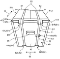
外側端部41は、上縁部42と、下縁部43と、一対の側縁部44,45と、正面部46とを含む。正面部46は、長手方向Dに略垂直な長方形の端面47を有している。上縁部42は、上部被覆部19aよりも上方に突出する凸形状を有している。下縁部43は、下部被覆部19bよりも下方に突出する凸形状を有している。上縁部42は、下縁部43に対して鉛直方向に対向する位置にあり、互いに略平行である。一対の側縁部44,45は、幅方向Wの両側に位置し、側部被覆部19c,19dよりも側方に突出する凸形状をそれぞれ有している。側縁部44は、側縁部45に対して水平方向に対向する位置にあり、互いに略平行である。
The outer end portion 41 includes an
上縁部42、下縁部43及び側縁部44,45の突出高さは、被覆部19a〜19dに被覆される板状梱包材13の厚み以上に設定されている。これにより、室内機91が梱包された状態では、板状梱包材13が外側端部41よりも出っ張るのが抑制される。
The protruding heights of the
上縁部42は、略水平方向に延びる上面42aと、この上面42aと端面47とをつなぐ傾斜面42bとを含む。この傾斜面42bは、端面47に向かって長手方向Dに対して下方に傾斜している。下縁部43は、略水平方向に延びる下面43aと、この下面43aと端面47とをつなぐ傾斜面43bとを含む。この傾斜面43bは、端面47に向かって長手方向Dに対して上方に傾斜している。一方の側縁部44は、略鉛直方向に延びる側面44aと、この側面44aと端面47とをつなぐ傾斜面44bとを含む。他方の側縁部45は、略鉛直方向に延びる側面45aと、この側面45aと端面47とをつなぐ傾斜面45bとを含む。これらの傾斜面44b,45bは、端面47に向かって長手方向Dに対して傾斜している。
The
上縁部42には、梱包用バンド93を位置決めする役割を担い、梱包用バンドが配置される一対の第1位置決め部61(61R,61L)が設けられている。一方の第1位置決め部61Rは、緩衝梱包材11を正面視したときに、端面47の幅方向(左右方向)の中央よりも右側の位置に設けられている。他方の第1位置決め部61Lは、緩衝梱包材11を正面視したときに、端面47の幅方向(左右方向)の中央よりも左側の位置に設けられている。
The
下縁部43には、梱包用バンド93を位置決めする役割を担い、梱包用バンドが配置される一対の第2位置決め部62(62R,62L)が設けられている。一方の第2位置決め部62Rは、緩衝梱包材11を正面視したときに、端面47の幅方向(左右方向)の中央よりも右側の位置に設けられている。他方の第2位置決め部62Lは、緩衝梱包材11を正面視したときに、端面47の幅方向(左右方向)の中央よりも左側の位置に設けられている。右側の第2位置決め部62Rは、右側の第1位置決め部61Rの真下(鉛直方向下方)に位置しており、左側の第2位置決め部62Lは、左側の第1位置決め部61Lの真下(鉛直方向下方)に位置している。
The
各第1位置決め部61は、上縁部42に形成された凹状の領域であり、上縁部42の傾斜面42bと略平行な底面611を有している。各第1位置決め部61の下端は、端面47に入り込んでいる。各第2位置決め部61は、下縁部43に形成された凹状の領域であり、下縁部43の傾斜面43bと略平行な底面621を有している。各第2位置決め部61の上端は、端面47に入り込んでいる。
Each
一方の梱包用バンド93は、第1位置決め部61Rの底面611と第2位置決め部62Rの底面621と通って緩衝梱包材11に巻き付けられる。この梱包用バンド93は、底面611の左側端部から右側端部までの範囲、及び底面621の左側端部から右側端部までの範囲であれば任意の位置に配置可能である。同様に、他方の梱包用バンド93は、第1位置決め部61Lの底面611の左側端部から右側端部までの範囲、及び第2位置決め部62Lの底面621の左側端部から右側端部までの範囲であれば任意の領域に配置可能である。
One
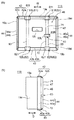
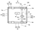
端面47には、第1位置決め部61Rと第2位置決め部62Rとの間において梱包用バンド93が通る領域の一部に凹部63が設けられている。凹部63は、梱包用バンド93の延びる方向(鉛直方向)の寸法よりもこれに直交する直交方向(水平方向)の寸法の方が長い細長形状(長方形状)を有している。凹部63は、端面47における高さ方向の中央よりも下方に設けられている。
The
図3(A)に示す形態では、梱包用バンド93が巻き付けられたときに、梱包用バンド93に対して水平方向の両方に凹部63の一部が露出する露出領域63R,63Lが存在する。この場合、作業者は、左右の露出領域63R,63Lのいずれからでも手の指を梱包用バンド93と凹部63との間に容易に差し入れることができる。
In the form shown in FIG. 3A, when the
凹部63の左右方向の開口寸法は、梱包用バンド93の幅、第1位置決め部61の幅、及び第2位置決め部62の幅などに応じて適宜調整される。本実施形態では、凹部63の左側の端部は、第1位置決め部61Rの左側の端部及び第2位置決め部62Rの左側の端部と鉛直方向にほぼ一致する位置にあり、凹部63の右側の端部は、第1位置決め部61Rの右側の端部及び第2位置決め部62Rの右側の端部と鉛直方向にほぼ一致する位置にある。一例を挙げると、この凹部63の左右方向の寸法は、例えば40mm〜50mm程度に設定される。
The opening dimension in the left-right direction of the
凹部63の高さ方向(鉛直方向)の開口寸法は、指が入る大きさに調整される。一例を挙げると、凹部63の高さ方向の開口寸法は、例えば15mm〜20mm程度に設定される。凹部63の奥行き(方向Dの凹み寸法)は、指が入る大きさ(数十mm程度)に調整される。
The opening dimension in the height direction (vertical direction) of the
凹部63と第1位置決め部61Rとの間には、梱包用バンド93の内面が当接又は近接する第1平坦面71が介在している。また、凹部63と第2位置決め部62Rとの間には、梱包用バンド93の内面が当接又は近接する第2平坦面72が介在している。第1平坦面71は、第1位置決め部61Rの下端から凹部63の上端まで連続する平面である。第2平坦面72は、凹部63の下端から第1位置決め部61Rの上端まで連続する平面である。本実施形態では、端面47は、凹部63及び後述する把持部95を除く領域がほぼ連続する平面であり、この平面に第1平坦面71及び第2平坦面72が含まれている。なお、第1平坦面71及び第2平坦面72を含む前記連続する平面には、例えば印字などのために設けられた多少の凹凸、ラベル貼り付け用の凹み寸法の小さい凹部、デザイン性を高めるために設けられた多少の凹凸などがあってもよい。
Between the
正面部46は、端面47から長手方向Dに凹む把持部95が設けられている。この把持部95は、作業者が梱包品を運搬する際に把持する部位であり、端面47の幅方向(左右方向)のほぼ中央に位置し、高さ方向の中央よりも上方に位置している。把持部95は、各梱包用バンド93を配置可能な前記領域に重ならない位置に設けられている。
The
<板状梱包材>
図1に示すように、板状梱包材13は、天面部31、底面部32及び一対の側面部33,34を含む筒形状に折り曲げられる。板状梱包材13は、一対の緩衝梱包材11の内側被覆部19に跨って配設される。板状梱包材13は、周方向の端部同士が天面部31において突き合わされ、又は重ね合わされており、室内機91の周囲を囲んでいる。
<Plate-shaped packing material>
As shown in FIG. 1, the plate-shaped
天面部31は、長手方向Dに直交する幅方向Wの一方に位置する角部K11において折り曲げられる第1折り曲げ片51と、幅方向の他方に位置する角部K12において折り曲げられる第2折り曲げ片52とにより構成されている。
The
<梱包手順>
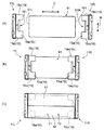
本実施形態では、梱包材10を用いて、次のような手順で室内機91の梱包作業が行われる。まず、図4(A),(B)に示すように、室内機91における長手方向Dの端部91R,91Lに緩衝梱包材11R,11Lをそれぞれ嵌合する。この状態では、図4(B)に示すように、室内機91の端部91R,91Lに嵌合された一対の緩衝梱包材11R,11Lは、互いに離隔している。したがって、室内機91の両端部91R,91L以外の部分は、緩衝梱包材11では覆われていない。
<Packing procedure>
In the present embodiment, the packing operation of the
ついで、折り曲げられていない展開した状態の板状梱包材13を、緩衝梱包材11及び室内機91の下に配置し、室内機91の周囲を囲むように筒形状に折り曲げる(図4(C)参照)。この状態では、板状梱包材11は、右側緩衝梱包材11Rの内側被覆部19と左側緩衝梱包材11Lの内側被覆部19との間に跨るように配置され、これらの内側被覆部19を覆っている。
Next, the unfolded unfolded plate-shaped
また、板状梱包材13の両端部、すなわち第1折り曲げ片51の端部と第2折り曲げ片52の端部は、天面部31において突き合わされているか、又は重ね合わされている。これらの端部同士は、例えば粘着テープなどを用いて互いに接合される。最後に、一対の帯状の梱包用バンド93,93を用いて被梱包物、緩衝梱包材11及び板状梱包材13を結束する。これにより、梱包品が完成する(図1参照)。
Further, both end portions of the plate-shaped
<変形例>
図5は、緩衝梱包材11の変形例を示す正面図である。この変形例では、凹部63は、端面47において、梱包用バンド93の延びる方向(鉛直方向)に直交する直交方向(水平方向)の一方に偏った位置に設けられている。しかも、梱包用バンド93が巻き付けられたときに、梱包用バンド93に対して水平方向の右側に露出する凹部63の露出領域63Rが水平方向の左側に露出する凹部63の露出領域63Lよりも大きい。
<Modification>
FIG. 5 is a front view showing a modified example of the buffer packing material 11. In this modified example, the recessed
この変形例では、凹部63の露出領域を上記のように偏在させるために、凹部63における前記直交方向の中央位置C3は、第1位置決め部61Rにおける前記直交方向の中央位置C1、及び第2位置決め部62Rにおける前記直交方向の中央位置C2よりも右側にずれた位置にある。
In this modification, in order to make the exposed region of the
この変形例では、凹部63の左側の端部は、第1位置決め部61Rの左側の端部及び第2位置決め部62Rの左側の端部と鉛直方向にほぼ一致する位置、又は第1位置決め部61Rの左側の端部及び第2位置決め部62Rの左側の端部よりも右側にある。凹部63の右側の端部は、第1位置決め部61Rの右側の端部及び第2位置決め部62Rの右側の端部よりも右側にある。
In this modification, the left end portion of the
図5では、露出領域63Lと露出領域63Rがともに存在する場合を例示しているが、少なくとも露出領域63Rが存在していればよく、凹部63の左側の領域は梱包用バンド93によって塞がれていてもよい。
FIG. 5 illustrates the case where both the exposed
以上説明したように、本実施形態では、緩衝梱包材の端面47には、梱包用バンド93が通る領域の一部に凹部63が設けられている。したがって、梱包用バンド93が巻き付けられた梱包品には、梱包用バンド93と凹部63との間に作業者が指を差し入れ可能な空間が形成される。これにより、複数の梱包品が横方向及び高さ方向に隙間なく配列された状態において、例えば最上段に配置されている梱包品の一つを取り出したいときに、作業者は、梱包用バンド93と凹部63との間に形成された前記空間に指を差し入れることができ、この差し入れた指によって梱包用バンド93を掴み、梱包品を片手で手前に容易に引き出すことができる。また、場合によっては、従来のような作業台も不要になる。したがって、製品の梱包に本構成の緩衝梱包材を用いることにより、梱包品の引き出し作業の作業性が向上する。
As described above, in the present embodiment, the
しかも、本実施形態では、凹部63と第1位置決め部61Rとの間には、梱包用バンド93の内面が当接又は近接する第1平坦面71が介在し、凹部63と第2位置決め部62Rとの間には、梱包用バンド93の内面が当接又は近接する第2平坦面72が介在している。このように端面において梱包用バンド93が通る領域のうち、凹部63、第1位置決め部61R及び第2位置決め部62R以外の領域は、第1平坦面71及び第2平坦面72によって構成されているので、凹部63の鉛直方向の両サイドの領域の肉厚を十分に厚くすることが可能となる。したがって、凹部63を設けることに起因する緩衝梱包材の強度低下を抑制することができる。また、梱包用バンド93が巻き付けられた状態では、第1平坦面71及び第2平坦面72には、梱包用バンド93が当接又は近接するので、梱包用バンド93の巻き付け状態が安定する。
Moreover, in the present embodiment, the first
また、本実施形態では、梱包用バンド93が巻き付けられた状態において、梱包用バンド93に対して前記直交方向の両方に凹部63の一部が露出するので、作業者は、この露出した領域から梱包用バンド93と凹部63との間に指を簡単に差し入れることが可能になる。これにより、梱包品の取り出し作業の作業性がより向上する。
Further, in the present embodiment, in a state where the
また、本実施形態では、凹部63が端面47における高さ方向の中央よりも下方に設けられているので、高さ方向の段積み数が多い場合であっても、作業者の手が凹部63に届きやすくなる。これにより、高い位置にある梱包品の取り出し作業の作業性がより向上する。
In the present embodiment, since the
また、変形例では、凹部63が端面47において、前記直交方向の右側に偏った位置に設けられており、梱包用バンド93に対して右側に露出する凹部63の露出領域63Rが左側に露出する凹部63の露出領域63Lよりも大きい。したがって、例えば梱包品の取り出し作業を右手で行う場合には、凹部63が端面47において右側に偏った位置にあり、かつ右側の露出領域63Rの方が大きいことによって、この右側の露出領域63Rに右手の指を差し入れやすくなる。しかも、端面47の右側に巻き付けられた梱包用バンド93を右手の指で引っ張る作業は、作業時のバランスがよく、作業者が力を入れやすいなどのメリットがあり、作業効率がさらに向上する。
Further, in the modification, the
以上、本発明の実施形態について説明したが、本発明は、上記各実施形態に限られるものではなく、その趣旨を逸脱しない範囲で種々変更、改良等が可能である。 Although the embodiments of the present invention have been described above, the present invention is not limited to the above-described embodiments, and various modifications and improvements can be made without departing from the spirit of the present invention.
例えば、前記実施形態では、梱包用バンド93が上縁部42、端面47及び下縁部43を通って巻き付けられる場合を例示したが、これに限定されない。例えば、梱包用バンド93は、側縁部44、端面47及び側縁部45を通って水平方向に巻き付けられる形態であってもよい。
For example, in the embodiment, the case where the
また、前記実施形態では、凹部63が端面47における高さ方向の中央よりも下方に設けられている場合を例示したが、これに限定されず、凹部63は、高さ方向の中央やこの中央よりも上方に設けられていてもよい。
Moreover, although the case where the recessed
また、前記実施形態では、上縁部42、下縁部43及び一対の側縁部44,45が傾斜面42b,43b,44b,45bを含む場合を例示したが、これに限定されず、これらの傾斜面は必須のものではない。
Moreover, in the said embodiment, although the case where the
10 梱包材
11 緩衝梱包材
13 板状梱包材
41 外側端部
42 上縁部
43 下縁部
44,45 側縁部
46 正面部
47 端面
61 第1位置決め部
62 第2位置決め部
63 凹部
71 第1平坦面
72 第2平坦面
91 被梱包物
93 梱包用バンド
DESCRIPTION OF SYMBOLS 10 Packing material 11
Claims (4)
前記一方の縁部(42)には、前記梱包用バンド(93)を位置決めする役割を担い、前記梱包用バンド(93)が配置される第1位置決め部(61)が設けられており、前記他方の縁部(43)には、前記梱包用バンド(93)を位置決めする役割を担い、前記梱包用バンド(93)が配置される第2位置決め部(62)が設けられており、前記端面(47)には、前記第1位置決め部(61)と前記第2位置決め部(62)との間において前記梱包用バンド(93)が通る領域の一部に凹部(63)が設けられており、
前記凹部(63)と前記第1位置決め部(61)との間には、前記梱包用バンド(93)の内面が当接又は近接する第1平坦面(71)が介在し、前記凹部(63)と前記第2位置決め部(62)との間には、前記梱包用バンド(93)の内面が当接又は近接する第2平坦面(72)が介在する緩衝梱包材。 A foamed plastic molded body that can be fitted to an end portion in one predetermined direction (D) of the article to be packed (91), an end surface (47) located in the one direction (D), and this end surface (47 ) And a pair of edge portions (42, 43) facing each other, and the band-shaped packing band (93) is fitted to the article to be packed (91), at least one edge portion (42), a buffer packing material that can be wound through the end face (47) and the other edge (43),
The one edge portion (42) has a role of positioning the packing band (93), and is provided with a first positioning portion (61) in which the packing band (93) is disposed, The other edge portion (43) has a role of positioning the packing band (93), and is provided with a second positioning portion (62) on which the packing band (93) is disposed, and the end face (47) is provided with a recess (63) in a part of the region through which the packing band (93) passes between the first positioning part (61) and the second positioning part (62). ,
Between the concave portion (63) and the first positioning portion (61), a first flat surface (71) with which the inner surface of the packing band (93) abuts or approaches is interposed, and the concave portion (63 ) And the second positioning portion (62), a cushioning packing material in which a second flat surface (72) with which the inner surface of the packing band (93) abuts or approaches is interposed.
The recess (63) is provided on the end surface (47) at a position biased to one of the orthogonal directions orthogonal to the extending direction of the packing band (93), and the packing band (93) is provided. When exposed, the exposed area of the recess (63) exposed in one of the orthogonal directions with respect to the packing band (93) is more exposed than the exposed area of the recess (63) exposed in the other of the orthogonal directions. The buffer packing material according to any one of claims 1 to 3, which is large.
Priority Applications (1)
| Application Number | Priority Date | Filing Date | Title |
|---|---|---|---|
| JP2011004075A JP2012144271A (en) | 2011-01-12 | 2011-01-12 | Cushioning packaging material |
Applications Claiming Priority (1)
| Application Number | Priority Date | Filing Date | Title |
|---|---|---|---|
| JP2011004075A JP2012144271A (en) | 2011-01-12 | 2011-01-12 | Cushioning packaging material |
Publications (1)
| Publication Number | Publication Date |
|---|---|
| JP2012144271A true JP2012144271A (en) | 2012-08-02 |
Family
ID=46788286
Family Applications (1)
| Application Number | Title | Priority Date | Filing Date |
|---|---|---|---|
| JP2011004075A Pending JP2012144271A (en) | 2011-01-12 | 2011-01-12 | Cushioning packaging material |
Country Status (1)
| Country | Link |
|---|---|
| JP (1) | JP2012144271A (en) |
Cited By (2)
| Publication number | Priority date | Publication date | Assignee | Title |
|---|---|---|---|---|
| JP2017081590A (en) * | 2015-10-27 | 2017-05-18 | ダイキン工業株式会社 | Packing cushioning material |
| WO2019064432A1 (en) * | 2017-09-28 | 2019-04-04 | 三菱電機株式会社 | Packing device |
Citations (3)
| Publication number | Priority date | Publication date | Assignee | Title |
|---|---|---|---|---|
| JPS5239464U (en) * | 1975-09-11 | 1977-03-19 | ||
| JPS58194162U (en) * | 1982-06-22 | 1983-12-23 | 株式会社東芝 | packaging equipment |
| JPH0687288U (en) * | 1993-05-31 | 1994-12-22 | 三洋電機株式会社 | Ventilation fan packaging |
-
2011
- 2011-01-12 JP JP2011004075A patent/JP2012144271A/en active Pending
Patent Citations (3)
| Publication number | Priority date | Publication date | Assignee | Title |
|---|---|---|---|---|
| JPS5239464U (en) * | 1975-09-11 | 1977-03-19 | ||
| JPS58194162U (en) * | 1982-06-22 | 1983-12-23 | 株式会社東芝 | packaging equipment |
| JPH0687288U (en) * | 1993-05-31 | 1994-12-22 | 三洋電機株式会社 | Ventilation fan packaging |
Cited By (2)
| Publication number | Priority date | Publication date | Assignee | Title |
|---|---|---|---|---|
| JP2017081590A (en) * | 2015-10-27 | 2017-05-18 | ダイキン工業株式会社 | Packing cushioning material |
| WO2019064432A1 (en) * | 2017-09-28 | 2019-04-04 | 三菱電機株式会社 | Packing device |
Similar Documents
| Publication | Publication Date | Title |
|---|---|---|
| JP5240251B2 (en) | Packing material | |
| KR20140002524A (en) | Packaging material and package | |
| KR200490607Y1 (en) | Panel transport container | |
| JP2012144271A (en) | Cushioning packaging material | |
| US20100032336A1 (en) | Package member | |
| JP2019137405A (en) | Packing apparatus | |
| JP6119675B2 (en) | Packing material | |
| JP4936933B2 (en) | Packing tray | |
| JP2007197081A (en) | Carton box for cartridge storage case | |
| JP5573807B2 (en) | Packaging equipment | |
| KR20110012742A (en) | Box for packing goods with improved storage structure | |
| KR20130001005U (en) | Packing box having fold type shock-absorbing matrial | |
| KR200457917Y1 (en) | Packing box | |
| JP3194118U (en) | Packing material | |
| JP2020083459A (en) | Packing material | |
| JP5773534B2 (en) | Packaging case | |
| KR200468148Y1 (en) | Packing box having dual cover | |
| JP6245962B2 (en) | Returnable packaging material | |
| JP6734765B2 (en) | palette | |
| KR101558300B1 (en) | Packing box | |
| JP2017001719A (en) | Internal holding material and packing equipment | |
| JP3198918U (en) | Buffer sheet and article storage unit | |
| JP7113981B2 (en) | package | |
| JP5784326B2 (en) | Packing material | |
| KR20110003266U (en) | A packing box for agricultural products |
Legal Events
| Date | Code | Title | Description |
|---|---|---|---|
| A621 | Written request for application examination |
Free format text: JAPANESE INTERMEDIATE CODE: A621 Effective date: 20131129 |
|
| A977 | Report on retrieval |
Free format text: JAPANESE INTERMEDIATE CODE: A971007 Effective date: 20140711 |
|
| A131 | Notification of reasons for refusal |
Free format text: JAPANESE INTERMEDIATE CODE: A131 Effective date: 20140729 |
|
| A02 | Decision of refusal |
Free format text: JAPANESE INTERMEDIATE CODE: A02 Effective date: 20141125 |