JP2012144159A - Friction circle radius deriving device - Google Patents
Friction circle radius deriving device Download PDFInfo
- Publication number
- JP2012144159A JP2012144159A JP2011004320A JP2011004320A JP2012144159A JP 2012144159 A JP2012144159 A JP 2012144159A JP 2011004320 A JP2011004320 A JP 2011004320A JP 2011004320 A JP2011004320 A JP 2011004320A JP 2012144159 A JP2012144159 A JP 2012144159A
- Authority
- JP
- Japan
- Prior art keywords
- circle radius
- road surface
- friction circle
- surface gradient
- vehicle
- Prior art date
- Legal status (The legal status is an assumption and is not a legal conclusion. Google has not performed a legal analysis and makes no representation as to the accuracy of the status listed.)
- Granted
Links
Images


Landscapes
- Steering Control In Accordance With Driving Conditions (AREA)
- Control Of Driving Devices And Active Controlling Of Vehicle (AREA)
Abstract
【課題】走行路の路面勾配が変化しても、正確な摩擦円半径を得ることができる摩擦円半径導出装置を提供する。
【解決手段】軌跡生成演算部は、まず地図データから、車両が走行しようとする走行路の路面勾配の情報を取得し、路面勾配を考慮しない走行軌跡を生成する。そして、軌跡生成演算部は、路面勾配及び車速等の情報に基づいて、路面に対する車輪の接地荷重を算出し、その接地荷重に基づいて、車両の実走行時における車輪の摩擦円半径(タイヤ発生能力)を求め、その摩擦円半径に基づいて、路面勾配を考慮した走行軌跡を生成する。
【選択図】図2There is provided a friction circle radius deriving device capable of obtaining an accurate friction circle radius even if a road surface gradient of a traveling road changes.
A trajectory generation calculation unit first acquires information on a road surface gradient of a road on which a vehicle is to travel from map data, and generates a travel trajectory that does not consider the road surface gradient. Then, the trajectory generation calculation unit calculates the ground contact load of the wheel with respect to the road surface based on the information such as the road surface gradient and the vehicle speed, and based on the ground contact load, the wheel frictional circle radius (tire generation) when the vehicle actually travels is calculated. Capacity) is determined, and a travel locus considering the road surface gradient is generated based on the friction circle radius.
[Selection] Figure 2
Description
本発明は、車両の車輪の摩擦円半径を導出する摩擦円半径導出装置に関するものである。 The present invention relates to a friction circle radius deriving device for deriving a friction circle radius of a vehicle wheel.
従来の摩擦円半径導出装置としては、例えば特許文献1に記載されているように、車両が走行する道路の路面摩擦係数の情報を取得し、その路面摩擦係数に応じて、車両が走行する道路上で車両のタイヤが発揮可能な最大グリップ力(摩擦円半径)を変更するものが知られている。
As a conventional friction circle radius deriving device, for example, as described in
しかしながら、上記従来技術においては、以下の問題点が存在する。即ち、車両が走行する道路の路面勾配が変化すると、タイヤの接地荷重が変化し、これに伴ってタイヤの摩擦円半径が変化するため、路面勾配を考慮しないと摩擦円半径の導出精度が低下するおそれがある。 However, the following problems exist in the prior art. In other words, if the road gradient of the road on which the vehicle travels changes, the tire ground contact load will change, and the friction circle radius of the tire will change accordingly, so the accuracy of deriving the friction circle radius will decrease unless the road gradient is taken into account. There is a risk.
本発明の目的は、走行路の路面勾配が変化しても、正確な摩擦円半径を得ることができる摩擦円半径導出装置を提供することである。 An object of the present invention is to provide a friction circle radius deriving device capable of obtaining an accurate friction circle radius even when the road surface gradient of a traveling road changes.
本発明は、車両の車輪の摩擦円半径を導出する摩擦円半径導出装置において、車両が走行する走行路の路面勾配の情報を取得する勾配情報取得手段と、路面勾配を含む情報に基づいて車輪の接地荷重を算出する接地荷重算出手段とを備え、接地荷重に基づいて車輪の摩擦円半径を導出することを特徴とするものである。 The present invention relates to a friction circle radius deriving device for deriving a friction circle radius of a wheel of a vehicle, a gradient information acquisition means for acquiring information on a road surface gradient of a traveling road on which the vehicle travels, and a wheel based on information including the road surface gradient. And a ground load calculating means for calculating the ground load of the wheel, and the friction circle radius of the wheel is derived based on the ground load.
このように本発明の摩擦円半径導出装置においては、車両が走行する走行路の路面勾配の情報を取得し、路面勾配を含む情報に基づいて車両の車輪の接地荷重を算出し、その接地荷重に基づいて車輪の摩擦円半径を導出することにより、走行路の路面勾配に応じて変化する車輪の接地荷重が考慮された摩擦円半径が導出されるようになる。これにより、走行路の路面勾配が変化しても、正確な摩擦円半径を得ることができる。 Thus, in the friction circle radius deriving device of the present invention, information on the road surface gradient of the traveling road on which the vehicle travels is obtained, the ground load of the vehicle wheel is calculated based on the information including the road surface gradient, and the ground load is calculated. By deriving the frictional circle radius of the wheel based on this, the frictional circle radius in consideration of the ground contact load of the wheel that changes in accordance with the road surface gradient of the traveling road is derived. As a result, an accurate friction circle radius can be obtained even if the road surface gradient of the traveling road changes.
好ましくは、接地荷重算出手段は、路面勾配の変化方向を考慮して接地荷重を算出する。この場合には、走行路の路面勾配が上りから下りに変化する際の接地荷重の抜けや、走行路の路面勾配が下りから上りに変化する際の接地荷重の増加等が考慮された一層正確な摩擦円半径を得ることができる。 Preferably, the ground load calculation means calculates the ground load in consideration of the change direction of the road surface gradient. In this case, more accurate consideration is given to the loss of ground load when the road surface gradient of the road changes from ascending to down and the increase of the ground load when the road surface gradient of the road changes from down to up. A large friction circle radius can be obtained.
また、好ましくは、接地荷重算出手段は、路面勾配及び車両の横加速度を含む情報に基づいて接地荷重を算出する。例えば車両がカーブ路を走行すると、車両の横加速度により車両の車体がカーブ外側に沈み込むため、車輪の接地荷重が変化する。そこで、走行路の路面勾配及び車両の横加速度を含む情報に基づいて車輪の接地荷重を算出することにより、カーブ走行時においても正確な摩擦円半径を得ることができる。 Preferably, the contact load calculating means calculates the contact load based on information including a road surface gradient and a lateral acceleration of the vehicle. For example, when the vehicle travels on a curved road, the vehicle body sinks to the outside of the curve due to the lateral acceleration of the vehicle, so that the ground contact load of the wheel changes. Therefore, by calculating the wheel contact load based on information including the road surface gradient of the travel road and the lateral acceleration of the vehicle, an accurate friction circle radius can be obtained even during curve travel.
本発明によれば、走行路の路面勾配が変化しても、正確な摩擦円半径を得ることができる。 According to the present invention, an accurate friction circle radius can be obtained even when the road surface gradient of the traveling road changes.
以下、本発明に係わる摩擦円半径導出装置の好適な実施形態について、図面を参照して詳細に説明する。 Preferred embodiments of a friction circle radius deriving device according to the present invention will be described below in detail with reference to the drawings.
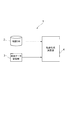
図1は、本発明に係わる摩擦円半径導出装置の一実施形態を備えた走行軌跡生成装置の概略構成を示すブロック図である。同図において、走行軌跡生成装置1は、地図データベース2と、車両データ記憶部3と、軌跡生成演算部4とを備えている。
FIG. 1 is a block diagram showing a schematic configuration of a travel locus generating apparatus including an embodiment of a friction circle radius deriving device according to the present invention. In FIG. 1, the travel
地図データベース2には、道路の路面勾配情報を含んだ地図データが格納されている。車両データ記憶部3には、車両諸元やタイヤ特性マップ(後述)等の車両データが予め記憶されている。
The
軌跡生成演算部4は、地図データベース2に格納された地図データに含まれる道路の路面勾配情報と車両データ記憶部3に記憶された車両データとを入力し、所定の演算処理を行い、車両の走行軌跡を生成する。
The trajectory
図2は、軌跡生成演算部4により実行される走行軌跡生成処理手順の詳細を示すフローチャートである。図2において、まず地図データベース2に格納された地図データから、車両が走行しようとする走行路の路面勾配の情報(勾配の変化方向や角度等)を取得する(手順S11)。なお、路面勾配は、路面のピッチ方向の勾配だけでなく、路面のロール方向の勾配も含んでいる。
FIG. 2 is a flowchart showing details of the travel locus generation processing procedure executed by the locus
続いて、例えば走行ライン、加速度(摩擦円の使い方ルール)及び運動モデルを設計条件とした既知の走行軌跡生成技術を用いて、路面勾配を考慮しない走行軌跡を生成する(手順S12)。 Subsequently, a travel locus that does not consider the road surface gradient is generated using a known travel locus generation technique using, for example, a travel line, acceleration (rules for using a friction circle), and a motion model as a design condition (step S12).
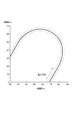
例えば図3に示すように、車両が一定勾配(勾配角θが一定、勾配変化dθ/dL=0、Lは距離)を有する単一U字カーブを走行する場合には、図4に示すような走行軌跡が生成される。図4は、走行軌跡として走行速度(車速)を走行路の形状と共に立体的に表示したものである。図4中の太実線Pは、路面勾配を考慮しない走行軌跡を示している。この走行軌跡は、カーブに向かうに従って速度が下がり、カーブの入口に達すると速度がほぼ一定となり、カーブの出口手前から速度が上がるように設定されている。 For example, as shown in FIG. 3, when the vehicle travels on a single U-shaped curve having a constant gradient (gradient angle θ is constant, gradient change dθ / dL = 0, L is a distance), as shown in FIG. A smooth travel locus is generated. FIG. 4 shows a three-dimensional display of the traveling speed (vehicle speed) as a traveling locus together with the shape of the traveling path. A thick solid line P in FIG. 4 indicates a travel locus that does not consider the road surface gradient. This travel locus is set so that the speed decreases as it goes to the curve, the speed becomes almost constant when it reaches the entrance of the curve, and the speed increases from before the exit of the curve.
続いて、路面に対する車輪の接地荷重を算出する(手順S13)。具体的には、手順S11で取得された路面の勾配角θ、手順S12で生成された走行軌跡のうちの車速V、車両データ記憶部3に記憶された車両諸元から、前輪接地荷重Wfθ、後輪接地荷重Wrθを算出する。車両諸元としては、質量m、ピッチ慣性モーメントI、前輪−重心間距離lf、後輪−重心間距離lr、重力加速度gがある。
Subsequently, the ground contact load of the wheel with respect to the road surface is calculated (step S13). Specifically, the front wheel ground load W fθ is calculated from the road surface gradient angle θ acquired in step S11, the vehicle speed V of the travel locus generated in step S12, and the vehicle specifications stored in the vehicle
まず図5に示すように、車両の運動方程式により下記式が得られる。

そして、上記の(b)式、(c)式より、前輪接地荷重Wfθ及び後輪接地荷重Wrθが算出される。
ここで、図3に示すように車両が一定勾配を有する単一U字カーブを走行する場合には、勾配変化dθ/dLは0となるため、前輪接地荷重Wfθは、以下のように導き出される。
後輪接地荷重Wrθも同様に、以下のように導き出される。
また、路面勾配の変化方向によって前輪接地荷重Wfθ及び後輪接地荷重Wrθが異なる。具体的には、路面勾配が上りから下りに変化するときは、前輪接地荷重Wfθ及び後輪接地荷重Wrθが減少し、路面勾配が下りから上りに変化するときは、前輪接地荷重Wfθ及び後輪接地荷重Wrθが増加する。 Further, the front wheel ground load W fθ and the rear wheel ground load W rθ are different depending on the change direction of the road surface gradient. Specifically, when the road gradient changes from ascending to descending, the front wheel contact load W fθ and the rear wheel contact load W rθ decrease, and when the road gradient changes from descending to ascending, the front wheel contact load W fθ. And the rear wheel ground load W rθ increases.
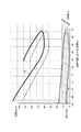
続いて、手順S13で算出された前輪接地荷重Wfθ及び後輪接地荷重Wrθから、車両の実走行時における車輪の摩擦円半径(タイヤ発生能力)を求める(手順S14)。具体的には、図6に示すように、車両データ記憶部3に記憶されたタイヤ特性マップを用いて、前輪接地荷重Wfθ及び後輪接地荷重Wrθに対応する摩擦円半径rを導出する。
Subsequently, the friction circle radius (tire generation capability) of the wheel during actual traveling of the vehicle is obtained from the front wheel contact load W fθ and the rear wheel contact load W rθ calculated in step S13 (procedure S14). Specifically, as shown in FIG. 6, using the tire characteristic map stored in the vehicle
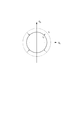
一定勾配のある勾配路を走行する場合の前輪接地荷重Wfθ及び後輪接地荷重Wrθは、勾配が無い平坦路を走行する場合の前輪接地荷重Wf0及び後輪接地荷重Wr0よりも低くなる。このため、一定勾配のある勾配路を走行する場合の摩擦円半径rθは、図7に示すように、平坦路を走行する場合の摩擦円半径r0よりも小さくなる。摩擦円半径rθは、具体的には下記のようになる。
rθ=r0×cosθ
The front wheel ground load W fθ and the rear wheel ground load W rθ when traveling on a gradient road with a constant gradient are lower than the front wheel ground load W f0 and the rear wheel ground load W r0 when traveling on a flat road without a gradient. Become. For this reason, as shown in FIG. 7, the frictional circle radius r θ when traveling on a gradient road having a constant gradient is smaller than the frictional circle radius r 0 when traveling on a flat road. Specifically, the friction circle radius rθ is as follows.
r θ = r 0 × cos θ
このとき、摩擦円破綻は接地荷重が小さい側で発生するため、前輪接地荷重Wfθ及び後輪接地荷重Wrθのうち小さいほうの摩擦円半径rを、勾配路を走行する場合の摩擦円半径rθとして設定する。前輪接地荷重Wfθは、2つの前輪の接地荷重Wの平均値であり、後輪接地荷重Wrθは、2つの後輪の接地荷重Wの平均値である。 At this time, since the friction circle failure occurs on the side where the ground contact load is small, the smaller friction circle radius r of the front wheel ground load W fθ and the rear wheel ground load W rθ is used as the friction circle radius when traveling on a gradient road. set as r θ. The front wheel ground load W fθ is an average value of the ground load W of the two front wheels, and the rear wheel ground load W rθ is an average value of the ground load W of the two rear wheels.
ただし、摩擦円破綻は4輪のうち1輪でも破綻すると良くないという点を考慮すると、手順S12で生成された走行軌跡に基づき、車両の横加速度による左右輪の接地荷重変化も加味して4輪の接地荷重を算出し、その4輪の接地荷重の最小値に対応する摩擦円半径rを摩擦円半径rθとして設定しても良い。また、前後輪及び左右輪を考慮せず、4輪の接地荷重の平均から摩擦円半径rθを導出しても良い。 However, in consideration of the fact that it is not good that one of the four wheels breaks down due to the friction circle failure, based on the travel locus generated in step S12, the change in the grounding load of the left and right wheels due to the lateral acceleration of the vehicle is taken into account. calculating a vertical load wheels may be set friction circle radius r corresponding to the minimum value of the ground contact load of the 4-wheel as the friction circle radius r theta. Further, the frictional circle radius rθ may be derived from the average of the contact loads of the four wheels without considering the front and rear wheels and the left and right wheels.
続いて、手順S14で求めた摩擦円半径rに基づいて、路面勾配を考慮した走行軌跡を生成する(手順S15)。車両が一定勾配を有する走行路を走行するときは、摩擦円半径rが一律に減少する。このため、図3に示すように車両が一定勾配を有する単一U字カーブを走行する場合における路面勾配を考慮した走行軌跡としては、図4中の細実線Qで示すようなものとなる。このとき、勾配の無い平坦路を走行する場合に対し(太実線P参照)、車両の走行ラインも若干異なるが、大きな速度差が生じるようになる。 Subsequently, based on the friction circle radius r obtained in step S14, a travel locus in consideration of the road surface gradient is generated (step S15). When the vehicle travels on a traveling road having a constant gradient, the friction circle radius r decreases uniformly. For this reason, as shown in FIG. 3, when the vehicle travels on a single U-shaped curve having a constant gradient, the traveling locus considering the road surface gradient is as shown by a thin solid line Q in FIG. At this time, when traveling on a flat road without a gradient (see the thick solid line P), the traveling line of the vehicle is slightly different, but a large speed difference is generated.
続いて、摩擦円半径の演算回数が予め決められた回数になったかどうかを判断する(手順S16)。摩擦円半径の演算回数が予め決められた回数になっていないときは、手順S13に戻り、手順S13〜S15を繰り返し実行し、摩擦円半径の演算回数が予め決められた回数になったときは、本処理を終了する。 Subsequently, it is determined whether or not the number of calculation of the friction circle radius has reached a predetermined number (step S16). When the number of times of calculation of the friction circle radius is not the predetermined number, the process returns to step S13, and steps S13 to S15 are repeatedly executed, and when the number of calculation of the friction circle radius reaches the predetermined number of times. This process is terminated.
最初に路面勾配を考慮しない走行軌跡に基づいて摩擦円半径を求めるだけでは、摩擦円半径に誤差が生じる可能性があるが、路面勾配を考慮した走行軌跡に基づいて摩擦円半径を再計算することで、摩擦円半径の精度を向上させることができる。 If the friction circle radius is simply calculated based on the travel locus that does not consider the road gradient first, an error may occur in the friction circle radius, but the friction circle radius is recalculated based on the travel locus that considers the road gradient. As a result, the accuracy of the friction circle radius can be improved.
以上において、軌跡生成演算部4の上記手順S11は、車両が走行する走行路の路面勾配の情報を取得する勾配情報取得手段を構成する。同手順S12,S13は、路面勾配を含む情報に基づいて車両の車輪の接地荷重を算出する接地荷重算出手段を構成する。同手順S14は、接地荷重に基づいて車輪の摩擦円半径を導出する手段を構成する。
In the above, the procedure S11 of the trajectory
以上のように本実施形態にあっては、車両が走行する走行路の路面勾配情報を取得し、その路面勾配を考慮しない走行軌跡を生成し、路面勾配情報及び路面勾配を考慮しない走行軌跡等に基づいて、当該走行路の路面に対するタイヤの接地荷重を算出し、その接地荷重に基づいてタイヤの摩擦円半径を導出するので、路面勾配の変化に応じて接地荷重が変化しても、正確な摩擦円半径を得ることができる。そして、そのような摩擦円半径に基づいて、路面勾配を考慮した走行軌跡を生成するので、車両の適切な走行軌跡を生成することができる。 As described above, in the present embodiment, road surface gradient information of a traveling road on which a vehicle travels is acquired, a travel locus that does not consider the road surface gradient is generated, a road locus that does not consider the road surface gradient information and the road surface gradient, and the like. Therefore, the tire's ground contact load on the road surface of the road is calculated, and the friction circle radius of the tire is derived based on the contact load, so even if the ground load changes according to the change in the road surface gradient, A large friction circle radius can be obtained. And since the driving | running | working locus | trajectory which considered the road surface gradient is produced | generated based on such a friction circle radius, the suitable driving | running locus | trajectory of a vehicle can be produced | generated.
このとき、路面勾配が上りから下りに変化するときは、接地荷重が抜けるため、摩擦円半径が小さくなるが、摩擦円破綻を引き起こすことなく走行することができる。また、路面勾配が下りから上りに変化するときは、接地荷重が増大し、摩擦円半径が大きくなるため、タイヤ発生能力の増加分の性能を生かした走行を行うことができる。 At this time, when the road surface gradient changes from ascending to descending, since the ground contact load is lost, the friction circle radius becomes small, but the vehicle can travel without causing the friction circle failure. Further, when the road surface gradient changes from descending to ascending, the ground contact load increases and the frictional circle radius increases, so that it is possible to travel using the increased performance of the tire generation capability.
また、車両の横加速度による左右輪の接地荷重変化を加味して摩擦円半径を導出する場合には、カーブ走行時の横加速度によるカーブ外側への車体の沈み込みを原因とする接地荷重の変化を考慮した適切な摩擦円半径を得ることができる。 In addition, when the frictional circle radius is derived by taking into account the change in the ground load on the left and right wheels due to the lateral acceleration of the vehicle, the change in the ground load caused by the vehicle body sinking to the outside of the curve due to the lateral acceleration during curve driving It is possible to obtain an appropriate friction circle radius considering the above.
1…走行軌跡生成装置(摩擦円半径導出装置)、2…地図データベース、3…車両データ記憶部、4…軌跡生成演算部(勾配情報取得手段、接地荷重算出手段)。
DESCRIPTION OF
Claims (3)
前記車両が走行する走行路の路面勾配の情報を取得する勾配情報取得手段と、
前記路面勾配を含む情報に基づいて前記車輪の接地荷重を算出する接地荷重算出手段とを備え、
前記接地荷重に基づいて前記車輪の摩擦円半径を導出することを特徴とする摩擦円半径導出装置。 In a friction circle radius deriving device for deriving a friction circle radius of a vehicle wheel,
Gradient information acquisition means for acquiring road surface gradient information of a travel path on which the vehicle travels;
A contact load calculating means for calculating a contact load of the wheel based on information including the road surface gradient;
A friction circle radius deriving device, wherein a friction circle radius of the wheel is derived based on the ground load.
3. The friction circle radius deriving device according to claim 1, wherein the contact load calculation unit calculates the contact load based on information including the road surface gradient and a lateral acceleration of the vehicle.
Priority Applications (1)
| Application Number | Priority Date | Filing Date | Title |
|---|---|---|---|
| JP2011004320A JP5541170B2 (en) | 2011-01-12 | 2011-01-12 | Friction circle radius deriving device |
Applications Claiming Priority (1)
| Application Number | Priority Date | Filing Date | Title |
|---|---|---|---|
| JP2011004320A JP5541170B2 (en) | 2011-01-12 | 2011-01-12 | Friction circle radius deriving device |
Publications (2)
| Publication Number | Publication Date |
|---|---|
| JP2012144159A true JP2012144159A (en) | 2012-08-02 |
| JP5541170B2 JP5541170B2 (en) | 2014-07-09 |
Family
ID=46788203
Family Applications (1)
| Application Number | Title | Priority Date | Filing Date |
|---|---|---|---|
| JP2011004320A Expired - Fee Related JP5541170B2 (en) | 2011-01-12 | 2011-01-12 | Friction circle radius deriving device |
Country Status (1)
| Country | Link |
|---|---|
| JP (1) | JP5541170B2 (en) |
Cited By (1)
| Publication number | Priority date | Publication date | Assignee | Title |
|---|---|---|---|---|
| WO2016079836A1 (en) * | 2014-11-19 | 2016-05-26 | 株式会社安川電機 | Driving force control system for electric vehicle, electric vehicle, rotary electric machine |
Citations (3)
| Publication number | Priority date | Publication date | Assignee | Title |
|---|---|---|---|---|
| JP2004323004A (en) * | 2003-04-22 | 2004-11-18 | Continental Ag | Shock-absorbing control method |
| JP2010105454A (en) * | 2008-10-28 | 2010-05-13 | Advics Co Ltd | Control device for vehicle |
| JP2010270628A (en) * | 2009-05-19 | 2010-12-02 | Fuji Heavy Ind Ltd | Vehicle driving force control device |
-
2011
- 2011-01-12 JP JP2011004320A patent/JP5541170B2/en not_active Expired - Fee Related
Patent Citations (3)
| Publication number | Priority date | Publication date | Assignee | Title |
|---|---|---|---|---|
| JP2004323004A (en) * | 2003-04-22 | 2004-11-18 | Continental Ag | Shock-absorbing control method |
| JP2010105454A (en) * | 2008-10-28 | 2010-05-13 | Advics Co Ltd | Control device for vehicle |
| JP2010270628A (en) * | 2009-05-19 | 2010-12-02 | Fuji Heavy Ind Ltd | Vehicle driving force control device |
Cited By (1)
| Publication number | Priority date | Publication date | Assignee | Title |
|---|---|---|---|---|
| WO2016079836A1 (en) * | 2014-11-19 | 2016-05-26 | 株式会社安川電機 | Driving force control system for electric vehicle, electric vehicle, rotary electric machine |
Also Published As
| Publication number | Publication date |
|---|---|
| JP5541170B2 (en) | 2014-07-09 |
Similar Documents
| Publication | Publication Date | Title |
|---|---|---|
| JP5914448B2 (en) | Saddle-type vehicle and wheel force acquisition device | |
| JP5831560B2 (en) | Deceleration factor estimation device and driving support device | |
| CN113978457B (en) | Method and device for predicting collision risk | |
| CN106515739B (en) | A kind of electric car ramp identification device and method | |
| CN103661393A (en) | Kinematic road gradient estimation | |
| JP2017024460A (en) | Device for estimating flooding on road surface | |
| JP5652055B2 (en) | Vehicle vibration estimation device and vehicle system vibration control device using the same | |
| US11002539B2 (en) | Method for detecting a slope of a road | |
| JP2012046037A (en) | Device for estimating vehicle body vibration, and control device for suppressing vehicle body vibration using the same | |
| CN114555456A (en) | Tilting vehicle data output apparatus | |
| WO2016039197A1 (en) | Method and device for speed change control of a bicycle | |
| US20200130701A1 (en) | Pseudo-emotion generation method, travel evaluation method, and travel evaluation system | |
| JP2013216278A (en) | Grounding load estimation device | |
| JP5752633B2 (en) | Speed detection device, travel position calculation device, and speed calculation method | |
| JP5652054B2 (en) | Body vibration estimation device | |
| CN116749778A (en) | Energy recovery methods, devices, storage media and vehicles | |
| CN104105630A (en) | Decelerating factor-estimating device | |
| JP5541170B2 (en) | Friction circle radius deriving device | |
| JP2010047237A (en) | Grade inferring device and its method | |
| JP5180610B2 (en) | Vehicle driving force control device | |
| JP2009275560A (en) | Driving force control device of vehicle | |
| CN115697805A (en) | Vehicle motion control device and vehicle motion control method | |
| KR102165989B1 (en) | Method and apparatus of determining driving parameter of electric vehicle | |
| JP5913248B2 (en) | In-vehicle display device | |
| CN106919896A (en) | Road edge identification system and method and use its vehicle |
Legal Events
| Date | Code | Title | Description |
|---|---|---|---|
| A621 | Written request for application examination |
Free format text: JAPANESE INTERMEDIATE CODE: A621 Effective date: 20130516 |
|
| A131 | Notification of reasons for refusal |
Free format text: JAPANESE INTERMEDIATE CODE: A131 Effective date: 20140204 |
|
| A521 | Request for written amendment filed |
Free format text: JAPANESE INTERMEDIATE CODE: A523 Effective date: 20140320 |
|
| TRDD | Decision of grant or rejection written | ||
| A01 | Written decision to grant a patent or to grant a registration (utility model) |
Free format text: JAPANESE INTERMEDIATE CODE: A01 Effective date: 20140408 |
|
| A61 | First payment of annual fees (during grant procedure) |
Free format text: JAPANESE INTERMEDIATE CODE: A61 Effective date: 20140421 |
|
| R151 | Written notification of patent or utility model registration |
Ref document number: 5541170 Country of ref document: JP Free format text: JAPANESE INTERMEDIATE CODE: R151 |
|
| LAPS | Cancellation because of no payment of annual fees |