JP2012144153A - Vehicle door structure - Google Patents
Vehicle door structure Download PDFInfo
- Publication number
- JP2012144153A JP2012144153A JP2011004211A JP2011004211A JP2012144153A JP 2012144153 A JP2012144153 A JP 2012144153A JP 2011004211 A JP2011004211 A JP 2011004211A JP 2011004211 A JP2011004211 A JP 2011004211A JP 2012144153 A JP2012144153 A JP 2012144153A
- Authority
- JP
- Japan
- Prior art keywords
- door
- vehicle
- flow path
- air flow
- air
- Prior art date
- Legal status (The legal status is an assumption and is not a legal conclusion. Google has not performed a legal analysis and makes no representation as to the accuracy of the status listed.)
- Granted
Links
Images

Landscapes
- Air-Conditioning For Vehicles (AREA)
Abstract
【課題】ドア内の空気流路を流れる温調空気の温度変化を抑制可能な車両用ドア構造を得る。
【解決手段】空気流路34を構成するダクト部材32の下方にシール部材42が配置される。インナーウエザーストリップ24には、シール部44が形成され、ドアインナーパネル18に接触している。シール部材42及びシール部44により、空気流路34の周囲に断熱空気層46が構成される。ドア内で対流した空気は、断熱空気層46には流れ込まない。
【選択図】図2A vehicle door structure capable of suppressing temperature change of temperature-controlled air flowing through an air flow path in a door is obtained.
A seal member is disposed below a duct member constituting an air flow path. A seal portion 44 is formed on the inner weather strip 24 and is in contact with the door inner panel 18. A heat insulating air layer 46 is formed around the air flow path 34 by the seal member 42 and the seal portion 44. Air convected in the door does not flow into the insulating air layer 46.
[Selection] Figure 2
Description
本発明は、車両用ドア構造に関し、さらに詳しくは、ドア内に、温調空気が流れる空気流路が構成された車両用ドア構造に関する。 The present invention relates to a vehicle door structure, and more particularly to a vehicle door structure in which an air flow path through which temperature-controlled air flows is configured in the door.
自動車に適用される車両用ドア構造として、特許文献1には、フロントドア及びリヤドアのドアトリムの上部にダクトを取り付けた構造が示されている。この構造では、ダクトには冷風を通すことで、後部座席に冷風を送風することが可能とされている。 As a vehicle door structure applied to an automobile, Patent Document 1 discloses a structure in which a duct is attached to upper portions of door trims of a front door and a rear door. In this structure, it is possible to blow cool air to the rear seat by passing cool air through the duct.
ところで、ダクトをドア内に単に配置すると、空調装置(エアコンディショナー等)で温度等が調整された空気(「温調空気」という)がダクト内を流れるとき、ドア内におけるダクト周囲の空気と熱移動してしまう。特に、ドア内で空気の対流(循環)が生じると、ダクト内の温調空気と、ダクト外部の対流空気との間で移動する熱量が多くなり、ダクト内の温調空気の温度を維持することが難しい。 By the way, when the duct is simply placed in the door, when the air whose temperature is adjusted by the air conditioner (air conditioner, etc.) (referred to as “temperature-controlled air”) flows in the duct, the air and heat around the duct in the door It will move. In particular, when air convection (circulation) occurs in the door, the amount of heat that moves between the temperature-controlled air in the duct and the convective air outside the duct increases, and the temperature of the temperature-controlled air in the duct is maintained. It is difficult.
本発明は上記事実を考慮し、ドア内の空気流路を流れる温調空気の温度変化を抑制可能な車両用ドア構造を得ることを課題とする。 This invention considers the said fact and makes it a subject to obtain the vehicle door structure which can suppress the temperature change of the temperature control air which flows through the air flow path in a door.
請求項1に記載の発明では、車両のドア内に配置され、内部を温調空気が流れる空気流路を構成するダクト部材と、前記ドア内に設けられ、前記空気流路の周囲の少なくとも一部の空間を、ドア内の他の空間から隔離し断熱空気層とする隔離部材と、を有する。 According to the first aspect of the present invention, the duct member is disposed in the door of the vehicle and forms an air flow path through which the temperature-controlled air flows. The duct member is provided in the door, and at least one around the air flow path. And an isolation member that isolates the space of the part from other spaces in the door to form an insulating air layer.
この車両用ドア構造では、ドア内において、ダクト部材によって構成された空気流路を温調空気が流れる。 In this vehicle door structure, temperature-controlled air flows through an air flow path constituted by a duct member in the door.
ドア内には、隔離部材が設けられている。隔離部材は、空気流路の周囲の少なくとも一部の空間を、ドア内の他の空間と隔離する、隔離された空間は、断熱空気層となる。すなわち、ドア内で空気の対流が生じても、この対流空気は断熱空気層には対流しない。したがって、ダクト部材が断熱空気層と接している部分では、空気流路の温調空気と、断熱空気層の空気とで移動する熱量が少なくなる。このため、このような断熱空気層がない構成と比較して、空気流路を流れる温調空気の温度変化を抑制できる。 A separating member is provided in the door. The isolation member isolates at least a part of the space around the air flow path from other spaces in the door, and the isolated space becomes a heat insulating air layer. That is, even if air convection occurs in the door, the convection air does not convection to the adiabatic air layer. Accordingly, in the portion where the duct member is in contact with the heat insulating air layer, the amount of heat that moves between the temperature-controlled air in the air flow path and the air in the heat insulating air layer is reduced. For this reason, the temperature change of the temperature control air which flows through an air flow path can be suppressed compared with the structure without such a heat insulation air layer.
請求項2に記載の発明では、請求項1に記載の発明において、前記ドア内に配置されてドアを構成するドア構成部品を備え、前記隔離部材の少なくとも一部が、前記ドア構成部品に設けられている。 According to a second aspect of the present invention, in the first aspect of the present invention, a door component that is disposed in the door and constitutes the door is provided, and at least a part of the isolation member is provided in the door component. It has been.
このように、隔離部材の少なくとも一部を、ドア構成部品に設けることで、隔離部材の全部をドア構成部品と別体で設けたものと比較して、部品点数を少なくすることができる。 As described above, by providing at least a part of the isolation member in the door component, the number of parts can be reduced as compared with a case in which the isolation member is provided separately from the door component.
請求項3に記載の発明では、請求項2に記載の発明において、前記ドア構成部品として、前記ドアを構成し車幅方向外側に位置するドアアウターパネルと、前記ドアを構成し前記ドアアウターパネルよりも車幅方向内側に位置するドアインナーパネルと、前記ドアインナーパネルに構成された孔部と、前記孔部を覆うカバー部材と、を有し、前記隔離部材の一部が前記カバー部材に設けられている。 According to a third aspect of the present invention, in the second aspect of the present invention, as the door component part, a door outer panel that constitutes the door and is positioned on the outer side in the vehicle width direction, and the door outer panel that constitutes the door. A door inner panel located on the inner side in the vehicle width direction, a hole formed in the door inner panel, and a cover member that covers the hole, and a part of the isolation member is in the cover member Is provided.
この車両用ドア構造では、ドアアウターパネルとドアインナーパネルとを備えると共に、ドアインナーパネルに構成された孔部(たとえばサービスホール等)を、カバー部材(たとえばサービスホールカバー等)で覆うことができる。そして、隔離部材の一部が、ドア構成部品であるカバー部材に設けられているので、隔離部材をドア構成部品と別体であらたに設けたものと比較して、部品点数を少なくすることができる。 In this vehicle door structure, a door outer panel and a door inner panel are provided, and a hole (for example, a service hole) formed in the door inner panel can be covered with a cover member (for example, a service hole cover). . And since a part of the separating member is provided on the cover member which is a door component, the number of parts can be reduced compared to a case where the separating member is provided separately from the door component. it can.
請求項4に記載の発明では、請求項1〜請求項3のいずれか1項に記載の発明において、前記隔離部材の少なくとも一部が、前記ダクト部材に設けられている。 In invention of Claim 4, in invention of any one of Claims 1-3, at least one part of the said isolation member is provided in the said duct member.
このように、隔離部材の少なくとも一部をダクト部材に設けることで、隔離部材の全部をダクト部材と別体で設けたものと比較して、部品点数を少なくすることができる。 Thus, by providing at least a part of the separating member on the duct member, the number of parts can be reduced as compared with the case where the entire separating member is provided separately from the duct member.
なお、請求項2に記載の発明と請求項4に記載の発明の双方を満たした発明とすることも可能である。すなわち、隔離部材の一部をドア構成部品に設け、他の一部をダクト部材に設ける構成としてもよい。また、隔離部材の少なくとも一部を、カバー部材及びダクト部材と一体化してもよい。
In addition, it is also possible to set it as the invention which satisfy | filled both the invention of
請求項5に記載の発明では、請求項1〜請求項4のいずれか1項に記載の発明において、前記ドアを構成し車室内側において車両の内装の一部を成す内装材を備え、前記空気流路が前記ダクト部材と前記内装材とで構成されている。 The invention according to claim 5 is the invention according to any one of claims 1 to 4, further comprising an interior material that constitutes the door and forms part of the interior of the vehicle on the vehicle interior side, An air flow path is constituted by the duct member and the interior material.
このように、空気流路を、ダクト部材と内装材とで構成すると、空気流路をダクト部材のみで構成したものと比較して、ダクト部材の一部が不要となるので、低コスト化及び軽量化を図ることが可能になる。 As described above, when the air flow path is constituted by the duct member and the interior material, a part of the duct member is not required as compared with the case where the air flow path is constituted only by the duct member. It is possible to reduce the weight.
請求項6に記載の発明では、請求項1〜請求項5のいずれか1項に記載の発明において、前記断熱空気層が、前記ダクト部材の長手方向と直交する断面で見て前記空気流路よりも少なくとも車室に対し外側に構成されている。 In the invention according to claim 6, in the invention according to any one of claims 1 to 5, the air flow path when the heat insulating air layer is seen in a cross section orthogonal to the longitudinal direction of the duct member. It is configured outside at least with respect to the passenger compartment.
このように、断熱空気層を空気流路よりも少なくとも車室に対し外側に構成することで、空気流路と車両外部(外気)との熱移動を効果的に抑制できる。 As described above, the heat transfer between the air flow path and the outside of the vehicle (outside air) can be effectively suppressed by configuring the adiabatic air layer outside the air flow path at least with respect to the passenger compartment.
請求項7に記載の発明では、請求項1〜請求項5のいずれか1項に記載の発明において、前記断熱空気層が、前記ダクト部材の長手方向と直交する断面で見て前記空気流路を取り囲むように構成されている。 According to a seventh aspect of the present invention, in the invention according to any one of the first to fifth aspects of the present invention, the heat insulating air layer is seen from a cross section perpendicular to the longitudinal direction of the duct member. Is configured to surround.
このように、断熱空気層を、空気流路を取り囲むように構成することで、空気流路の周囲の全体で熱移動を効果的に抑制できる。 In this way, by configuring the heat insulating air layer so as to surround the air flow path, heat transfer can be effectively suppressed around the entire air flow path.
本発明は上記構成としたので、ドア内の空気流路を流れる温調空気の温度変化を抑制できる。 Since this invention was set as the said structure, the temperature change of the temperature control air which flows through the air flow path in a door can be suppressed.
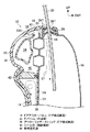
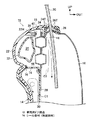
図1には、本発明の第1実施形態の車両用ドア構造12が適用された車両のフロントドア14が側面視にて示されている。また、図2及び図3には、このフロントドア14が図1における2−2線断面、3−3線断面でそれぞれ示されている。各図面において、車両前方を矢印FRで、車両上方を矢印UPで、車幅方向外側を矢印OUTでそれぞれ示している。
FIG. 1 shows a
図2及び図3に示すように、フロントドア14は、車幅方向外側に位置するドアアウターパネル16と、このドアアウターパネル16よりも車幅方向内側に位置するドアインナーパネル18とを有している。ドアアウターパネル16とドアインナーパネル18とは、たとえば互いの外周部分で接合されており、ドアアウターパネル16とドアインナーパネル18との間に所定の空間が構成されている。この空間には、ウインドウガラス20を昇降可能に支持するための、図示しないウインドウレギュレータが配置されている。
As shown in FIGS. 2 and 3, the
ドアインナーパネル18よりもさらに車幅方向内側には、車両の内装を構成する内装材としてのドアトリム22が配置され、図示しない留め具等の固定部材により、ドアインナーパネル18に固定されている。ドアインナーパネル18とドアトリム22との間にも、所定の空間が構成されている。
Further on the inner side in the vehicle width direction than the door
ドアトリム22の上部には、インナーウエザーストリップ24が取り付けられている。インナーウエザーストリップ24の先端24Tは、車両前後方向の全域にわたってウインドウガラス20に接触しており、フロントドア14の内部への埃等の異物の進入を抑制している。同様に、ドアアウターパネル16の上部にもアウターウエザーストリップ26が取り付けられており、その先端26Tがウインドウガラス20に接触することで、フロントドア14の内部への異物や雨水の進入を抑制している。
An
図1に示すように、ドアインナーパネル18を車幅方向に見たときの略中央には、サービスホール28が形成されている。サービスホール28は、通常はサービスホールカバー30によって閉塞されているが、サービスホールカバー30を取り外すことで、サービスホール28を通じてドアインナーパネル18とドアアウターパネル16の間の空間にアクセス可能となる。
As shown in FIG. 1, a
ドアインナーパネル18とドアトリム22の間の空間の上部には、車両前後方向に沿ってダクト部材32が配置されている。第1実施形態では、ダクト部材32は筒状に形成されており、内部が空気流路34とされている。
A
ダクト部材32の車両前後方向の前端は前開口部32Fとされており、ドアインナーパネル18の前壁部18Fに開口している。また、ダクト部材32の車両前後方向の後端は後開口部32Rとされており、ドアインナーパネル18の後壁部18Rにそれぞれ開口している。図示しない空調装置から送られた温調空気が、図示しないインストルメントパネル内のダクトを経て、前開口部32Fからダクト部材32の内部(空気流路34)に導入される。さらにこの温調空気は、ダクト部材32内の空気流路34を通り、後開口部32Rから排出される。排出された温調空気は、さらに、車体のピラー等に設けられた空気流路を通り、リヤドアの空気流路等に送られる。
The front end of the
ダクト部材32及びドアトリム22には、必要に応じて、図1に示すように車室内に向けてレジスタ孔36が設けられている。ダクト部材32内の空気流路34を流れる温調空気の一部を、このレジスタ孔36から車室内に供給することができる。
The
ダクト部材32の上部からは、斜め上方に向けて取付片38が延出され、ダクト部材32の下部からも、斜め下方に向けて取付片38が延出されている。取付片38には取付ネジ40が挿通され、さらにこの取付ネジ40が、ドアトリム22から延出された取付片の取付孔22Hに螺合されることで、ダクト部材32がドアトリム22に取り付けられている。なお、取付片38は、図1に示すように、車両前後方向には間隔をあけて複数設けられており、ダクト部材32は車両前後方向の複数箇所でドアトリム22に取り付けられている。
From the upper part of the
ダクト部材32の下方には、サービスホール28よりも上方の位置(本実施形態では、サービスホール28の上縁と略同じ高さ)に、本発明における「隔離部材」の一部を構成するシール部材42が配置されている。図1から分かるように、シール部材42は略長尺状に形成されており、車両前後方向に延在されている。
Below the
シール部材42の前部及び後部は、ドアインナーパネル18の前壁部18Fに達している。同様に、シール部材42の車両後方側端部は、ドアインナーパネル18の後壁部18Rに達している。特に本実施形態では、図2から分かるように、シール部材42の前部及び後部は、ドアインナーパネル18の前壁部18F及び後壁部18Rの縁部に沿って上方に立ち上げられている。そして、図3から分かるように、この立ち上げ片42Sが、ドアトリム22とドアインナーパネル18との隙間D1を塞いでいる(図3では車両後方側のみ示しているが、車両前方側も略同様である)。なお、このような隙間D1を塞ぐための部材があらかじめ設けられている車両の場合には、立ち上げ片42Sを形成する必要はない。
The front portion and the rear portion of the
また、図2から分かるように、シール部材42の車幅方向両端部は、ドアインナーパネル18又はドアトリム22にそれぞれ密着されており、接着等によって密着性が維持されている。
As can be seen from FIG. 2, both end portions in the vehicle width direction of the
シール部材42としては、所定の弾性を有するゴムや樹脂材料を用いることができる。たとえば、エチレンプロピレンゴムは、ドアインナーパネル18やドアトリム22に対する高い密着性を確保でき、対候性や耐熱性にも優れるので、好ましい。
As the
図2から分かるように、さらにインナーウエザーストリップ24には、シール部44が形成されている。シール部44は、インナーウエザーストリップ24の車両前後方向の全域において、ドアインナーパネル18に接触している。インナーウエザーストリップ24は、ドア構成部品の一例であり、このドア構成部品であるインナーウエザーストリップ24に、隔離部材の一部をなすシール部44が設けられていることになる。
As can be seen from FIG. 2, a
シール部44は、上記したシール部材42と共に、本発明における「隔離部材」を構成している。すなわち、図2に示す断面において、フロントドア14の内部の空間(特に、ドアインナーパネル18とドアトリム22の間の空間)のうち、ダクト部材32の周囲の空間が、シール部材42及びシール部44によって他の空間から隔離されている。そして、ダクト部材32の周囲に、本発明における断熱空気層46が構成されている。断熱空気層46の内部は、フロントドア14内の他の空間において矢印C1で示すように空気が対流しても、この対流空気が流れ込まない構造である。
The
次に、本実施形態の車両用ドア構造12の作用を説明する。
Next, the operation of the
図示しない空調装置で生成された温調空気は、同じく図示しないインストルメントパネル内のダクトから、ダクト部材32の前開口部32Fを通じて、ダクト部材32の内部(空気流路34)に導入される。そして、空気流路34を車両後方側に向かって流れ、後開口部32Rから排出されて、車体のピラー等に設けられた空気流路から、リヤドアの空気流路等に送られる。なお、レジスタ孔36が設けられている場合には、ダクト部材32内の温調空気の一部が、レジスタ孔36を通って車室内にも供給される。
Temperature-controlled air generated by an air conditioner (not shown) is introduced from the duct in the instrument panel (not shown) into the duct member 32 (air flow path 34) through the
図2から分かるように、本実施形態の車両用ドア構造12では、ドアインナーパネル18とドアトリム22の間に構成される空間を、特にダクト部材32の周囲において、シール部材42及びシール部44によってシールすることで断熱空気層46を構成している。断熱空気層46では、フロントドア14内の他の空間で生じた対流空気(矢印C1)が流れ込まない。すなわち、ダクト部材32の内部を流れる温調空気の温度が、ダクト部材32の周辺の空気の温度の影響を受け難くなる。換言すれば、断熱空気層46がない構成の車両用ドア構造であれば、ドア内の対流によって空気流路34の周囲の空気が入れ代わるため、ダクト部材32の内部と外部との熱移動が多くなるが、これと比較して、本実施形態では、空気流路34の周囲(断熱空気層46)の空気の断熱効果により、ダクト部材32の内部の温調空気と、ダクト部材32の外側の空気との熱移動が少なくなる。このため、ダクト部材32内(空気流路34)を流れる温調空気の温度変化を抑制することが可能になる。
As can be seen from FIG. 2, in the
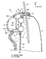
図4には、本発明の第2実施形態の車両用ドア構造62が示されている。また、図5には、第2実施形態の車両用ドア構造62が、図4の5−5線断面図で示されている。第2実施形態において、第1実施形態と同一の構成要素、部材等については同一符号を付して、詳細な説明を省略する。
FIG. 4 shows a
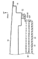
第2実施形態の車両用ドア構造12は、ダクト部材32とシール部材42とが、ダクト部材32から下方に延出された連続部64によって連結されている。すなわち、本発明の隔離部材の一部であるシール部材42が、ダクト部材32に設けられて、これらが一体化されている。なお、第2実施形態では、シール部材42を中空状としている。
In the
特に、本実施形態では、図4に示すように、連続部64が、車両前後方向で、取付片38と同位置に設定されている。
In particular, in the present embodiment, as shown in FIG. 4, the
このような構成とされた第2実施形態の車両用ドア構造62においても、第1実施形態の車両用ドア構造12と同様の作用効果を奏する。さらに、第2実施形態の車両用ドア構造62では、ダクト部材32とシール部材42とが一体化されていることで、第1実施形態の車両用ドア構造12と比較して、部品点数が少なくなる。
Also in the
また、ダクト部材32をフロントドア14内に所定位置に配置すれば、シール部材42も所定位置に配置できるので、組み付けや位置あわせの作業が容易になる。
Further, if the
特に、図3に示した例では、取付片38と連続部64とを車両前後方向の同位置に設定しているので、ダクト部材32にシール部材42の荷重が作用することによるダクト部材32の撓みを抑制できる。もちろん、連続部64が、取付片38と異なる位置に設けられていてもよい。
In particular, in the example shown in FIG. 3, since the
なお、隔離部材をダクト部材32に設けて一体化する構成としては、上記の他にも、たとえば、ダクト部材32の周囲にさらに筒状部材を配置して(二重筒状になる)、この外側の筒状部材とダクト部材32とを、1又は複数の連続部で連続させて一体化した構造でもよい。この構造では、ダクト部材32と筒状部材の間の空間が、断熱空気層46として作用する。
In addition to the above, as a configuration in which the separating member is provided in the
図6には、本発明の第3実施形態の第3実施形態の車両用ドア構造72が、図2及び図5と同様の断面にて示されている。第3実施形態においても、第1実施形態の車両用ドア構造12と同一の構成要素、部材等については同一符号を付して、詳細な説明を省略する。
FIG. 6 shows a
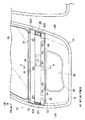
第3実施形態の車両用ドア構造72では、シール部材74が、サービスホールカバー30の上縁部分を車幅方向内側へ延出することにより構成されている。シール部材74の先端(車幅方向内側の端部)は車両前後方向の全域にわたってドアトリム22に達しており、接着剤76等により接着されている。さらに、シール部材74は、サービスホールカバー30よりも車両前方側及び車両後方側へも延出されており、実質的に、車両幅方向に見たときには、第1実施形態のシール部材42と略同形状とされている。サービスホールカバー30は、本発明のカバー部材であり、フロントドア14の構成部品の一部でもある。このサービスホールカバー30に、隔離部材の一部であるシール部材74が設けられている。
In the
このような構成とされた第3実施形態の車両用ドア構造72においても、第1実施形態の車両用ドア構造12や第2実施形態の車両用ドア構造62と同様の作用効果を奏する。さらに第3実施形態の車両用ドア構造72では、サービスホールカバー30とシール部材74とが一体化されていることで、第1実施形態の車両用ドア構造12と比較して、部品点数が少なくなる。
Also in the
また、サービスホールカバー30をドアインナーパネル18に対し所定位置(サービスホール28を閉塞する位置)に配置すれば、シール部材74も所定位置に配置できるので、組み付けや位置あわせの作業が容易になる。
Further, if the
図7には、本発明の第4実施形態の車両用ドア構造82が示されている。第3実施形態においても、第1実施形態の車両用ドア構造12と同一の構成要素、部材等については同一符号を付して、詳細な説明を省略する。
FIG. 7 shows a
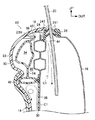
第4実施形態の車両用ドア構造82では、第3実施形態の車両用ドア構造72と同様に、サービスホールカバー30の上縁部分からシール部材74が延出されており、ドアトリム22に車両前後方向の全域で接触しているが、さらに、この接触部分から、ダクト部材84が延出されている。
In the
ダクト部材84は、車幅方向外側へと折り返された折り返し部84Aと、この折り返し部84Aから上方に延出された縦壁部84B、さらに縦壁部84Bからドアトリム22へと斜め上方に延出されてドアトリム22に接合される接合部84Cを有している。このような全体形状とされたダクト部材84と、内装材であるドアトリム22との間に、第1実施形態のダクト部材32と同様に空気流路34が構成されている。
The
また、この空気流路34よりも車幅方向外側には、シール部材74、ドアインナーパネル18、ダクト部材84及びドアトリム22の間に、断熱空気層46が構成されている。特に、折り返し部84Aとシール部材74との間に隙間46Pが構成されており、この隙間も断熱空気層46となっている。
A heat insulating
このような構成とされた第4実施形態の車両用ドア構造82では、図示しない空調装置からの温調空気が、ダクト部材84とドアトリム22との間に構成された空気流路34を流れる。空気流路34よりも車幅方向外側には断熱空気層46が構成されているので、このような断熱空気層46が無いものと比較して、空気流路34を流れる温調空気の温度変化を抑制することができる。
In the
さらに、第4実施形態の車両用ドア構造82では、サービスホールカバー30、シール部材74及びダクト部材84が一体化されているので、第2実施形態の車両用ドア構造62や第3実施形態の車両用ドア構造72と比較して、さらに部品点数が少なくなり、低コスト化、軽量化を図ることができる。
Furthermore, in the
また、サービスホールカバー30をドアインナーパネル18に対し所定位置(サービスホール28を閉塞する位置)に配置すれば、シール部材74及びダクト部材84も所定位置に配置できるので、組み付けや位置あわせの作業が容易になる。
Further, if the
加えて、ダクト部材84とシール部材74及びサービスホールカバー30を一体化したことで、これらの部材の干渉に伴う異音の発生を防止できる。しかも、干渉防止のためにあらかじめ隙間を設定しておく必要がなくなるので、スペース効率が高くなる。
In addition, since the
第4実施形態の車両用ドア構造82は、上記説明から分かるように、空気流路34に対し、車幅方向外側に断熱空気層46が位置している例である。断熱空気層としては、空気流路34の周囲の少なくとも一部に設けられていれば、断熱空気層がない構造と比較して断熱効果は高くなる。ただし、空気流路34に対し、車幅方向内側よりも車幅方向外側のほうが外気に近いので、熱の移動が生じやすい。したがって、断熱空気層46は、空気流路34の車幅方向外側を含む位置に設定すること(第4実施形態はその例である)が好ましく、さらには、空気流路34を全周で取り囲むように構成すること(第1〜第3実施形態及び後述する第5実施形態はその例である)が、より好ましい。
As can be seen from the above description, the
第2〜第4実施形態では、シール部材42、74(隔離部材)を、ダクト部材32あるいはサービスホールカバー30に設けて一体化した例を挙げているが、他のドア構成部品、たとえばドアインナーパネル18やドアトリム22に隔離部材を設けてもよい。
In the second to fourth embodiments, the
同様に、シール部44も、インナーウエザーストリップ24ではなく、ドアインナーパネル18やドアトリム22に設けて、これらの間を塞ぐようにしてもよい。
Similarly, the
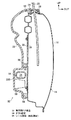
図8には、本発明の第5実施形態の車両用ドア構造92が示されている。第5実施形態においても、第1実施形態の車両用ドア構造12と同一の構成要素、部材等については同一符号を付して、詳細な説明を省略する。
FIG. 8 shows a
第5実施形態の車両用ドア構造92では、第1実施形態〜第4実施形態の車両用ドア構造と異なり、ダクト部材94が、フロントドア14内の下方に設けられている。すなわち、ドアトリム22の下部には、車幅方向内側に向かう膨出部22Bが構成されており、この膨出部22Bとドアインナーパネル18の間の空間に、ダクト部材94が配置されている。
In the
なお、この空間には、フロントドア14を構成する他部材96(たとえば外部から衝撃が作用した場合に衝撃のエネルギーを吸収するエネルギー吸収部材等)が配置されることがある。ダクト部材32は、このような他部材96を回避した位置(他部材96の作動に影響しない位置)に設けられる。
In this space, another member 96 (for example, an energy absorbing member that absorbs impact energy when an impact is applied from the outside) that constitutes the
膨出部22Bの上部及び下部には、ドアトリム22とドアインナーパネル18の間にシール部材98が配置されており、空気流路34(ダクト部材94の内部)の周囲を取り囲む断熱空気層46が構成されている。
A sealing
このように、ダクト部材32(空気流路34)位置は特に限定されない。断熱空気層46としても、空気流路34の位置に合わせて、その周囲の少なくとも一部の空間を、フロントドア14内の他の空間から隔離するように構成されていればよい。
Thus, the position of the duct member 32 (air flow path 34) is not particularly limited. The heat insulating
上記では、車両のフロントドア14に本発明の車両用ドア構造を適用した例を挙げたが、たとえば、リヤドアやバックドアに適用することも可能である。
Although the example which applied the vehicle door structure of this invention to the
12 車両用ドア構造
14 フロントドア
16 ドアアウターパネル(ドア構成部品)
18 ドアインナーパネル(ドア構成部品)
22 ドアトリム(内装材)
24 インナーウエザーストリップ(ドア構成部品)
26 アウターウエザーストリップ(ドア構成部品)
28 サービスホール(孔部)
30 サービスホールカバー(カバー部材)
32 ダクト部材
34 空気流路
42 シール部材(隔離部材)
44 シール部(隔離部材)
46 断熱空気層
62 車両用ドア構造
72 車両用ドア構造
74 シール部材(隔離部材)
82 車両用ドア構造
84 ダクト部材
92 車両用ドア構造
94 ダクト部材
98 シール部材(隔離部材)
12
18 Door inner panel (door component)
22 Door trim (interior material)
24 Inner weather strip (door components)
26 Outer weather strip (door components)
28 Service Hall (Hole)
30 Service hole cover (cover member)
32
44 Sealing part (isolation member)
46
82
Claims (7)
前記ドア内に設けられ、前記空気流路の周囲の少なくとも一部の空間を、ドア内の他の空間から隔離し断熱空気層とする隔離部材と、
を有する車両用ドア構造。 A duct member that is disposed in the door of the vehicle and forms an air flow path through which temperature-controlled air flows;
An isolation member provided in the door, wherein at least a part of the space around the air flow path is isolated from other spaces in the door to form a heat insulating air layer;
A vehicle door structure.
前記隔離部材の少なくとも一部が、前記ドア構成部品に設けられている請求項1に記載の車両用ドア構造。 Comprising door components arranged in the door and constituting the door;
The vehicle door structure according to claim 1, wherein at least a part of the isolation member is provided on the door component.
前記ドアを構成し車幅方向外側に位置するドアアウターパネルと、
前記ドアを構成し前記ドアアウターパネルよりも車幅方向内側に位置するドアインナーパネルと、
前記ドアインナーパネルに構成された孔部と、
前記孔部を覆うカバー部材と、
を有し、
前記隔離部材の一部が前記カバー部材に設けられている請求項2に記載の車両用ドア構造。 As the door component,
A door outer panel constituting the door and positioned on the outer side in the vehicle width direction; and
A door inner panel that constitutes the door and is positioned on the inner side in the vehicle width direction than the door outer panel;
A hole formed in the door inner panel;
A cover member covering the hole;
Have
The vehicle door structure according to claim 2, wherein a part of the isolation member is provided on the cover member.
前記空気流路が前記ダクト部材と前記内装材とで構成されている請求項1〜請求項4のいずれか1項に記載の車両用ドア構造。 An interior material that constitutes a part of the interior of the vehicle on the vehicle interior side constituting the door is provided,
The vehicle door structure according to any one of claims 1 to 4, wherein the air flow path is constituted by the duct member and the interior material.
Priority Applications (1)
| Application Number | Priority Date | Filing Date | Title |
|---|---|---|---|
| JP2011004211A JP5786338B2 (en) | 2011-01-12 | 2011-01-12 | Vehicle door structure |
Applications Claiming Priority (1)
| Application Number | Priority Date | Filing Date | Title |
|---|---|---|---|
| JP2011004211A JP5786338B2 (en) | 2011-01-12 | 2011-01-12 | Vehicle door structure |
Publications (2)
| Publication Number | Publication Date |
|---|---|
| JP2012144153A true JP2012144153A (en) | 2012-08-02 |
| JP5786338B2 JP5786338B2 (en) | 2015-09-30 |
Family
ID=46788199
Family Applications (1)
| Application Number | Title | Priority Date | Filing Date |
|---|---|---|---|
| JP2011004211A Expired - Fee Related JP5786338B2 (en) | 2011-01-12 | 2011-01-12 | Vehicle door structure |
Country Status (1)
| Country | Link |
|---|---|
| JP (1) | JP5786338B2 (en) |
Cited By (2)
| Publication number | Priority date | Publication date | Assignee | Title |
|---|---|---|---|---|
| KR20150118629A (en) * | 2014-04-14 | 2015-10-23 | 한온시스템 주식회사 | Air conditioning system for automotive vehicles |
| RU2718200C2 (en) * | 2015-09-28 | 2020-03-31 | Ман Трак Унд Бас Аг | Guiding device for bus door structure and bus |
Citations (4)
| Publication number | Priority date | Publication date | Assignee | Title |
|---|---|---|---|---|
| JPS61125820U (en) * | 1985-01-28 | 1986-08-07 | ||
| JPS61222811A (en) * | 1985-03-29 | 1986-10-03 | Nissan Shatai Co Ltd | Blast duct for vehicles |
| JPH0636909U (en) * | 1992-08-25 | 1994-05-17 | アラコ株式会社 | Door trim air duct structure |
| JP2005186799A (en) * | 2003-12-25 | 2005-07-14 | Inoac Corp | Duct for vehicle |
-
2011
- 2011-01-12 JP JP2011004211A patent/JP5786338B2/en not_active Expired - Fee Related
Patent Citations (4)
| Publication number | Priority date | Publication date | Assignee | Title |
|---|---|---|---|---|
| JPS61125820U (en) * | 1985-01-28 | 1986-08-07 | ||
| JPS61222811A (en) * | 1985-03-29 | 1986-10-03 | Nissan Shatai Co Ltd | Blast duct for vehicles |
| JPH0636909U (en) * | 1992-08-25 | 1994-05-17 | アラコ株式会社 | Door trim air duct structure |
| JP2005186799A (en) * | 2003-12-25 | 2005-07-14 | Inoac Corp | Duct for vehicle |
Cited By (3)
| Publication number | Priority date | Publication date | Assignee | Title |
|---|---|---|---|---|
| KR20150118629A (en) * | 2014-04-14 | 2015-10-23 | 한온시스템 주식회사 | Air conditioning system for automotive vehicles |
| KR101999602B1 (en) | 2014-04-14 | 2019-10-02 | 한온시스템 주식회사 | Air conditioning system for automotive vehicles |
| RU2718200C2 (en) * | 2015-09-28 | 2020-03-31 | Ман Трак Унд Бас Аг | Guiding device for bus door structure and bus |
Also Published As
| Publication number | Publication date |
|---|---|
| JP5786338B2 (en) | 2015-09-30 |
Similar Documents
| Publication | Publication Date | Title |
|---|---|---|
| JP5372165B2 (en) | Body front structure | |
| JP5758233B2 (en) | Automotive front structure | |
| US20150028629A1 (en) | Structure for front part of vehicle | |
| US20090146459A1 (en) | Cowl structure of vehicle | |
| JP5366242B2 (en) | Roof rack fastening device for sunroof vehicle | |
| JP5372164B2 (en) | Body front structure | |
| CN108688731A (en) | Vehicle front body structure | |
| JP5212189B2 (en) | Vehicle under-floor rectification structure | |
| US9573559B2 (en) | Front body structure of vehicle | |
| JP5786338B2 (en) | Vehicle door structure | |
| JP2009051328A (en) | Drain passage structure of pillar trim | |
| KR20140032775A (en) | Upper vehicle body structure of vehicle with a sun roof | |
| JP4407599B2 (en) | Body front support structure | |
| JP5109522B2 (en) | Vehicle sunroof structure | |
| JP2017087871A (en) | Rear body structure for automobile | |
| JP6630975B2 (en) | Body front structure | |
| JP6237669B2 (en) | Upper body structure of the vehicle | |
| JP6229675B2 (en) | Upper body structure of the vehicle | |
| JP6546470B2 (en) | Air conditioning duct connection structure | |
| WO2010113896A1 (en) | Front body structure of vehicle | |
| JP2006007982A (en) | Front structure of vehicle | |
| KR20080054821A (en) | Front pillar device | |
| JP2006306306A (en) | Fender garnish structure | |
| JP2014129005A (en) | Vehicle body internal structure | |
| JP2011131855A (en) | Cowl cover device |
Legal Events
| Date | Code | Title | Description |
|---|---|---|---|
| A621 | Written request for application examination |
Free format text: JAPANESE INTERMEDIATE CODE: A621 Effective date: 20131125 |
|
| A977 | Report on retrieval |
Free format text: JAPANESE INTERMEDIATE CODE: A971007 Effective date: 20140903 |
|
| A131 | Notification of reasons for refusal |
Free format text: JAPANESE INTERMEDIATE CODE: A131 Effective date: 20140909 |
|
| A521 | Request for written amendment filed |
Free format text: JAPANESE INTERMEDIATE CODE: A523 Effective date: 20141028 |
|
| A131 | Notification of reasons for refusal |
Free format text: JAPANESE INTERMEDIATE CODE: A131 Effective date: 20150217 |
|
| A521 | Request for written amendment filed |
Free format text: JAPANESE INTERMEDIATE CODE: A523 Effective date: 20150406 |
|
| TRDD | Decision of grant or rejection written | ||
| A01 | Written decision to grant a patent or to grant a registration (utility model) |
Free format text: JAPANESE INTERMEDIATE CODE: A01 Effective date: 20150630 |
|
| A61 | First payment of annual fees (during grant procedure) |
Free format text: JAPANESE INTERMEDIATE CODE: A61 Effective date: 20150713 |
|
| R151 | Written notification of patent or utility model registration |
Ref document number: 5786338 Country of ref document: JP Free format text: JAPANESE INTERMEDIATE CODE: R151 |
|
| LAPS | Cancellation because of no payment of annual fees |