JP2012144141A - Traveling body of tracklaying vehicle - Google Patents

Traveling body of tracklaying vehicle Download PDF

Info

Publication number
JP2012144141A
JP2012144141A JP2011003835A JP2011003835A JP2012144141A JP 2012144141 A JP2012144141 A JP 2012144141A JP 2011003835 A JP2011003835 A JP 2011003835A JP 2011003835 A JP2011003835 A JP 2011003835A JP 2012144141 A JP2012144141 A JP 2012144141A
Authority
JP
Japan
Prior art keywords
grease
greasing
slider
hydraulic motor
crawler belt
Prior art date
Legal status (The legal status is an assumption and is not a legal conclusion. Google has not performed a legal analysis and makes no representation as to the accuracy of the status listed.)
Pending
Application number
JP2011003835A
Other languages
Japanese (ja)
Inventor
Hironori Hamano
博紀 濱野
Current Assignee (The listed assignees may be inaccurate. Google has not performed a legal analysis and makes no representation or warranty as to the accuracy of the list.)
Hitachi Construction Machinery Co Ltd
Original Assignee
Hitachi Construction Machinery Co Ltd
Priority date (The priority date is an assumption and is not a legal conclusion. Google has not performed a legal analysis and makes no representation as to the accuracy of the date listed.)
Filing date
Publication date
Application filed by Hitachi Construction Machinery Co Ltd filed Critical Hitachi Construction Machinery Co Ltd
Priority to JP2011003835A priority Critical patent/JP2012144141A/en
Publication of JP2012144141A publication Critical patent/JP2012144141A/en
Pending legal-status Critical Current

Links

Images

Landscapes

  • Fluid-Pressure Circuits (AREA)

Abstract

PROBLEM TO BE SOLVED: To provide a travelling body of a tracklaying vehicle capable of reducing wear due to sliding contact between a slider and a track shoe and thereby extending the lives of the slider and the track shoe.SOLUTION: There is provided a grease supplier 24 for automatically supplying grease between the contact surface 23A of a slider 23 and the slider contact surface 19B of a track shoe 19. The grease supplier 24 constructed of a grease reservoir tank 25 for reserving the grease, a grease pump 26 for delivering the grease reserved in the reservoir tank 25, a grease supply hole 29 provided to the slider 23 and a grease supply pipe passage 28 connecting the grease supply hole 29 with the grease pump 26. Of the grease supply pipe passage 28, a portion exposed from a side frame 14 is covered by a protection cover 30.

Description

本発明は、例えば油圧ショベル、油圧クレーン等の履帯を備えた装軌式車両の走行体に関する。   The present invention relates to a traveling body of a tracked vehicle having a crawler track such as a hydraulic excavator or a hydraulic crane.

一般に、油圧ショベル、油圧クレーン等の装軌式車両は、自走可能な下部走行体と、該下部走行体上に旋回可能に搭載された上部旋回体と、該上部旋回体に設けられた作業装置とにより大略構成されている。   In general, a tracked vehicle such as a hydraulic excavator or a hydraulic crane has a self-propelled lower traveling body, an upper revolving body that is turnably mounted on the lower traveling body, and work provided on the upper revolving body. It is roughly constituted by the device.

ここで、例えば大型の装軌式車両の下部走行体は、センタフレームと該センタフレームの左,右両側で前,後方向に延びたサイドフレームとを有するトラックフレームと、該トラックフレームの各サイドフレームの長さ方向の一側に設けられた駆動輪と、各サイドフレームの長さ方向の他側に設けられた遊動輪と、駆動輪と遊動輪とに巻回して設けられた履帯と、各サイドフレームの上面側に設けられ駆動輪と遊動輪との間で履帯を案内するスライダとにより大略構成されている(例えば、特許文献1,2参照)。   Here, for example, a lower traveling body of a large tracked vehicle includes a track frame having a center frame and side frames extending in the front and rear directions on both left and right sides of the center frame, and each side of the track frame. A drive wheel provided on one side in the length direction of the frame, an idle wheel provided on the other side in the length direction of each side frame, a crawler belt wound around the drive wheel and the idle wheel, It is generally configured by a slider that is provided on the upper surface side of each side frame and guides the crawler belt between the driving wheel and the idler wheel (see, for example, Patent Documents 1 and 2).

このような下部走行体は、例えば走行用の油圧モータにより駆動輪を回転駆動することにより、該駆動輪の外周側を履帯の内側面に列設された突起に順次係合させ、該履帯を遊動輪との間で周回動作させることにより走行することができる。このとき、スライダは、履帯の内側面に摺接しつつ該履帯を下側から支持するように案内している。   Such a lower traveling body, for example, by rotationally driving the drive wheels by a traveling hydraulic motor, sequentially engages the outer peripheral side of the drive wheels with the protrusions arranged on the inner surface of the crawler belt, The vehicle can travel by rotating around the idler wheel. At this time, the slider is guided to support the crawler track from below while sliding on the inner surface of the crawler track.

特開2008−149899号公報JP 2008-149899 A 特開平9−277964号公報Japanese Patent Laid-Open No. 9-277964

従来技術によれば、互いに摺接(摩擦接触)するスライダと履帯との摩耗が進行し易く、これらスライダや履帯の寿命(交換時期)が短くなる虞がある。   According to the prior art, wear of the slider and the crawler belt that are in sliding contact with each other (friction contact) is likely to proceed, and the life (replacement time) of the slider and the crawler belt may be shortened.

本発明は上述した従来技術の問題に鑑みなされたもので、スライダと履帯との摺接による摩耗を低減することができ、これらスライダと履帯の寿命を延ばすことができる装軌式車両の走行体を提供することを目的としている。   The present invention has been made in view of the above-described problems of the prior art, and can reduce the wear caused by sliding contact between the slider and the crawler belt, and can extend the life of the slider and the crawler belt. The purpose is to provide.

上述した課題を解決するため本発明は、センタフレームと該センタフレームの左,右両側で前,後方向に延びたサイドフレームとを有するトラックフレームと、該トラックフレームの各サイドフレームの長さ方向の一側に設けられた駆動輪と、前記各サイドフレームの長さ方向の他側に設けられた遊動輪と、前記駆動輪と遊動輪とに巻回して設けられた履帯と、前記各サイドフレームに設けられ前記駆動輪と遊動輪との間で前記履帯を案内するスライダとを備えてなる装軌式車両の走行体に適用される。   In order to solve the above-described problems, the present invention provides a track frame having a center frame and side frames extending in the front and rear directions on the left and right sides of the center frame, and the length direction of each side frame of the track frame. A drive wheel provided on one side, idle wheels provided on the other side in the length direction of each side frame, crawler belts wound around the drive wheels and idle wheels, and each side The present invention is applied to a traveling body of a tracked vehicle that is provided on a frame and includes a slider that guides the crawler belt between the driving wheel and the idle wheel.

そして、請求項1の発明が採用する構成の特徴は、前記スライダと前記履帯との摺接部位に潤滑油を自動で供給する給脂装置を設ける構成としたことにある。   A feature of the configuration adopted by the invention of claim 1 is that a lubrication device is provided that automatically supplies lubricating oil to a sliding contact portion between the slider and the crawler belt.

請求項2の発明は、前記給脂装置は、前記摺接部位に対応して前記スライダに設けられた給脂孔と、該給脂孔に前記潤滑油を導く給脂管路とを有し、前記サイドフレームには、前記給脂管路のうち該サイドフレームから露出した部位を覆う保護カバーを設ける構成としたことにある。   According to a second aspect of the present invention, the greasing device has a greasing hole provided in the slider corresponding to the sliding contact portion, and a greasing pipe that guides the lubricating oil to the greasing hole. The side frame is provided with a protective cover that covers a portion of the grease supply pipe that is exposed from the side frame.

請求項3の発明は、油圧ポンプと、該油圧ポンプに主管路を介して接続され前記駆動輪を回転駆動する可変容量形の油圧モータと、該油圧モータの容量を可変に制御する容量制御回路と、前記主管路の途中に設けられる方向制御弁と、前記油圧モータの停止時に前記駆動輪に制動力を付与する駐車ブレーキと、前記容量制御回路の容量制御および/または前記駐車ブレーキのブレーキ制御を行うパイロット管路とを備え、前記給脂装置は、前記潤滑油を貯溜する貯油タンクと、該貯油タンク内に貯溜された潤滑油を吐出する給脂ポンプとを有し、該給脂ポンプは、前記パイロット管路のパイロット圧を動力として前記潤滑油を吐出する構成としたことにある。   According to a third aspect of the present invention, there is provided a hydraulic pump, a variable displacement type hydraulic motor connected to the hydraulic pump via a main line and rotationally driving the drive wheel, and a capacity control circuit for variably controlling the capacity of the hydraulic motor. A direction control valve provided in the middle of the main pipeline, a parking brake that applies a braking force to the drive wheel when the hydraulic motor is stopped, a capacity control of the capacity control circuit, and / or a brake control of the parking brake The grease supply device includes an oil storage tank that stores the lubricating oil, and a grease pump that discharges the lubricating oil stored in the oil storage tank. Is that the lubricating oil is discharged using the pilot pressure in the pilot line as power.

請求項1の発明によれば、スライダと履帯との摺接部位に潤滑油を自動で供給する給脂装置を設ける構成としているので、該給脂装置によりスライダと履帯との摺接部位を潤滑することができる。これにより、スライダと履帯との摩擦抵抗、摩耗を低減することができ、スライダと履帯の寿命(交換時期)を延ばすことができる。この結果、装軌式車両の走行体の耐久性、信頼性を高めることができる。   According to the first aspect of the present invention, since the lubrication device for automatically supplying the lubricating oil to the sliding contact portion between the slider and the crawler belt is provided, the sliding contact portion between the slider and the crawler belt is lubricated by the greasing device. can do. Thereby, the frictional resistance and wear between the slider and the crawler belt can be reduced, and the life (replacement time) of the slider and the crawler belt can be extended. As a result, the durability and reliability of the running body of the tracked vehicle can be improved.

請求項2の発明によれば、サイドフレームに給脂管路を覆う保護カバーを設ける構成としているので、給脂管路に土砂が直接堆積することを保護カバーにより防止することができ、給脂装置の耐久性、信頼性を高めることができる。   According to the second aspect of the present invention, the protective cover for covering the greasing pipeline is provided on the side frame, so that the protective cover can prevent sediment from being directly deposited on the greasing pipeline. The durability and reliability of the device can be improved.

請求項3の発明によれば、給脂装置を構成する給脂ポンプは、油圧モータの容量を制御する容量制御回路の容量制御および/または駐車ブレーキのブレーキ制御を行うパイロット管路のパイロット圧を動力としているので、装軌式車両の走行体の走行に合わせて給脂ポンプを駆動することができ、スライダと履帯との摺接部位を好適に潤滑することができる。これにより、更なる、耐久性、信頼性の向上を図ることができる。   According to the invention of claim 3, the grease pump constituting the grease supply device can control the pilot pressure of the pilot line for performing the capacity control of the capacity control circuit for controlling the capacity of the hydraulic motor and / or the brake control of the parking brake. Since the power is used, the greasing pump can be driven in accordance with the traveling of the traveling body of the tracked vehicle, and the sliding contact portion between the slider and the crawler belt can be suitably lubricated. Thereby, further improvement in durability and reliability can be achieved.

本発明の実施の形態による下部走行体を備えた油圧ショベルを示す正面図である。It is a front view which shows the hydraulic excavator provided with the lower traveling body by embodiment of this invention. 図1中の下部走行体を拡大して示す正面図である。It is a front view which expands and shows the lower traveling body in FIG. 下部走行体の右半部を履帯を省略した状態で示す平面図である。It is a top view which shows the right half part of a lower traveling body in the state which omitted the crawler belt. 履帯、スライダ、給脂管路、保護カバー等を示す図2中の(IV)部の拡大正面図である。It is an enlarged front view of the (IV) part in FIG. 2 which shows a crawler belt, a slider, a greasing line, a protective cover, etc. 履帯、スライダ、給脂管路、保護カバー等を示す図4中の矢示V−V方向からみた断面図である。It is sectional drawing seen from the arrow VV direction in FIG. 4 which shows a crawler belt, a slider, a greasing line, a protective cover, etc. 保護カバーを単体で示す斜視図である。It is a perspective view which shows a protective cover alone. 油圧ポンプ、油圧モータ、容量制御回路、駐車ブレーキ、パイロット管路、給脂装置等を示す回路構成図である。It is a circuit block diagram which shows a hydraulic pump, a hydraulic motor, a capacity | capacitance control circuit, a parking brake, a pilot pipe line, a greasing apparatus, etc. 走行レバーの位置、速度切換スイッチの位置、パイロット圧、駐車ブレーキ、グリース供給の時間変化を示す説明図である。It is explanatory drawing which shows the time change of the position of a travel lever, the position of a speed change switch, a pilot pressure, a parking brake, and grease supply.

以下、本発明の実施の形態に係る装軌式車両の走行体として、油圧ショベルの下部走行体を例に挙げ、添付図面に従って詳細に説明する。   Hereinafter, as a traveling body of a tracked vehicle according to an embodiment of the present invention, a lower traveling body of a hydraulic excavator will be described as an example and described in detail with reference to the accompanying drawings.

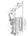
図中、1は装軌式車両としての大型の油圧ショベルを示している。この油圧ショベル1は、後述する下部走行体11と、該下部走行体11上に旋回輪2を介して旋回可能に搭載された上部旋回体3と、該上部旋回体3の前側に俯仰動可能に設けられ、土砂の掘削作業等を行う作業装置4とにより大略構成されている。   In the figure, reference numeral 1 denotes a large hydraulic excavator as a tracked vehicle. The hydraulic excavator 1 is a lower traveling body 11 to be described later, an upper revolving body 3 mounted on the lower traveling body 11 via a revolving wheel 2 so as to be able to swivel, and can be moved up and down to the front side of the upper revolving body 3. And a work device 4 that performs earth excavation work and the like.

次に、11は走行体としての装軌式(クローラ式)の下部走行体を示している。この装軌式の下部走行体11は、凹凸のある地面、泥濘地等を安定して走行するためのものである。そして、下部走行体11は、後述のトラックフレーム12、走行用油圧モータ15、駆動輪16、遊動輪17、履帯18、下ローラ21、スライダ23、給脂装置24等により構成されている。   Next, 11 shows a track type (crawler type) lower traveling body as a traveling body. The track-type lower traveling body 11 is for traveling stably on uneven ground, muddy ground, and the like. The lower traveling body 11 includes a track frame 12, a traveling hydraulic motor 15, a driving wheel 16, an idler wheel 17, a crawler belt 18, a lower roller 21, a slider 23, a greasing device 24, and the like, which will be described later.

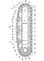
12は下部走行体11のトラックフレームである。このトラックフレーム12は、図2、図3等に示すように、左,右方向の中央部に位置するセンタフレーム13と、該センタフレーム13の左,右方向両側に設けられ前,後方向に延びた後述のサイドフレーム14とにより構成されている。   Reference numeral 12 denotes a track frame of the lower traveling body 11. As shown in FIGS. 2 and 3, the track frame 12 is provided with a center frame 13 located at the center in the left and right directions, and provided on both the left and right sides of the center frame 13 in the front and rear directions. It is comprised by the below-mentioned side frame 14 extended.

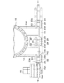
ここで、センタフレーム13は、左,右方向に延びる4個の脚部13Aを有したほぼH型の構造体として形成されている(図3中に右半分だけ図示)。また、センタフレーム13の中央には、旋回装置を構成する旋回輪2が取付けられ、該旋回輪2を介して上部旋回体3が搭載される。そして、センタフレーム13の各脚部13Aの先端には後述のサイドフレーム14が取付けられている。   Here, the center frame 13 is formed as a substantially H-shaped structure having four legs 13A extending in the left and right directions (only the right half is shown in FIG. 3). A turning wheel 2 constituting a turning device is attached to the center of the center frame 13, and the upper turning body 3 is mounted via the turning wheel 2. A side frame 14 described later is attached to the tip of each leg portion 13A of the center frame 13.

14はセンタフレーム13と共にトラックフレーム12を構成する左,右のサイドフレーム(右側のみ図示)を示している。このサイドフレーム14は、図3に示す如く、前,後方向に延びるように配置され、センタフレーム13の各脚部13A先端に取付けられている。   Reference numeral 14 denotes a left and right side frame (only the right side is shown) constituting the track frame 12 together with the center frame 13. As shown in FIG. 3, the side frame 14 is disposed so as to extend in the front and rear directions, and is attached to the tip of each leg portion 13 </ b> A of the center frame 13.

ここで、サイドフレーム14は、例えば短冊状の鋼板を溶接することにより前,後方向に延びる角筒状の製缶構造物として形成されている。即ち、サイドフレーム14は、センタフレーム13側となる左,右方向の内側に位置する垂直な内面板14Aと、該内面板14Aと左,右方向で対面する外側の外面板14Bと、内面板14Aと外面板14Bの上部間を連結した水平な上面板14Cと、内面板14Aと外面板14Bの下端部に固着された水平な下面板14Dとにより構成されている。   Here, the side frame 14 is formed, for example, as a rectangular tube-shaped can-making structure extending in the front and rear directions by welding strip-shaped steel plates. That is, the side frame 14 includes a vertical inner surface plate 14A located on the inner side in the left and right directions on the center frame 13 side, an outer surface plate 14B facing the inner surface plate 14A in the left and right directions, and an inner surface plate. The upper surface plate 14C is formed by connecting the upper portions of 14A and the outer surface plate 14B, and the inner surface plate 14A and the horizontal lower surface plate 14D fixed to the lower end portions of the outer surface plate 14B.

また、サイドフレーム14の長さ方向の一側と他側には、後述する駆動輪16と遊動輪17が設けられている。さらに、サイドフレーム14の下面板14Dには後述の下ローラ21が取付けられ、上面板14Cには後述のスライダ23が台座22を介して取付けられている。また、図4等に示すように、上面板14Cのうち台座22に対応する部位には、後述する給脂管路28を配設するための配管孔14C1が貫通して形成されている。   Further, drive wheels 16 and idle wheels 17 described later are provided on one side and the other side of the side frame 14 in the length direction. Further, a lower roller 21 described later is attached to the lower surface plate 14D of the side frame 14, and a slider 23 described later is attached to the upper surface plate 14C via a pedestal 22. Further, as shown in FIG. 4 and the like, a pipe hole 14C1 for arranging a greasing pipe 28 to be described later is formed through the portion corresponding to the pedestal 22 in the upper surface plate 14C.

15は後述の駆動輪16を回転駆動する油圧モータとしての走行用油圧モータである。この走行用油圧モータ15は、斜板式等の可変容量形の油圧モータにより構成され、各サイドフレーム14の長さ方向の一側(例えば図2の左側)に取付けられている。そして、走行用油圧モータ15は、後述のメインポンプ31(図7参照)が吐出する圧油により回転駆動され、駆動輪16を介して後述の履帯18を周回駆動するものである。   Reference numeral 15 denotes a traveling hydraulic motor as a hydraulic motor that rotationally drives a drive wheel 16 described later. The traveling hydraulic motor 15 is composed of a variable displacement hydraulic motor such as a swash plate, and is attached to one side of each side frame 14 in the length direction (for example, the left side in FIG. 2). The traveling hydraulic motor 15 is rotationally driven by pressure oil discharged from a main pump 31 (see FIG. 7), which will be described later, and drives the crawler belt 18, which will be described later, through the drive wheels 16.

16は各サイドフレーム14の長さ方向の一側に設けられたドライブタンブラと呼ばれる駆動輪である。この駆動輪16は、走行用油圧モータ15を介してサイドフレーム14に取付けられ、該走行用油圧モータ15を動力として後述の履帯18を周回駆動するものである。ここで、駆動輪16は、円環状に形成され、その内径側には、走行用油圧モータ15の出力軸とスプライン係合するスプライン孔(何れも図示せず)が設けられている。   Reference numeral 16 denotes a drive wheel called a drive tumbler provided on one side in the length direction of each side frame 14. The drive wheel 16 is attached to the side frame 14 via a traveling hydraulic motor 15 and drives the crawler belt 18 to be described later using the traveling hydraulic motor 15 as power. Here, the drive wheel 16 is formed in an annular shape, and a spline hole (none of which is shown) that is spline engaged with the output shaft of the traveling hydraulic motor 15 is provided on the inner diameter side thereof.

一方、駆動輪16の外径側には、軸方向に突出して多数個の噛合部16Aが周方向に等間隔で列設されている。これら各噛合部16Aは、後述の履帯18を構成する各トラックシュー19の係合突起19Aに噛合うもので、該各トラックシュー19を連結している間隔寸法に対応して突出間隔が設定されている。   On the other hand, on the outer diameter side of the drive wheel 16, a large number of meshing parts 16 </ b> A are arranged in the circumferential direction at regular intervals so as to protrude in the axial direction. Each of these meshing portions 16A meshes with an engagement projection 19A of each track shoe 19 constituting a crawler belt 18, which will be described later, and a projection interval is set corresponding to the interval dimension connecting each track shoe 19. ing.

17は各サイドフレーム14の長さ方向の他側(例えば図2の右側)に設けられたアイドラと呼ばれる遊動輪である。この遊動輪17は、履帯張り調整機構(図示せず)によって履帯18の張りを調整するもので、サイドフレーム14の長さ方向の他側に向け付勢されている。   Reference numeral 17 denotes an idler wheel called an idler provided on the other side in the length direction of each side frame 14 (for example, the right side in FIG. 2). The idler wheel 17 adjusts the tension of the crawler belt 18 by a crawler belt tension adjusting mechanism (not shown), and is biased toward the other side in the length direction of the side frame 14.

18は駆動輪16と遊動輪17とに巻回して設けられた履帯(クローラ)を示している。この履帯18は、図2および図4等に示すように、多数個のトラックシュー19を連結ピン20を用いて連結することにより無限軌道として構成されている。   Reference numeral 18 denotes a crawler belt (crawler) provided around the drive wheel 16 and the idle wheel 17. As shown in FIGS. 2 and 4, the crawler belt 18 is configured as an endless track by connecting a large number of track shoes 19 using connecting pins 20.

ここで、トラックシュー19には、図4および図5等に示すように、環状に連結された履帯18の内周側となる面に幅方向に所定の間隔をもって2個の係合突起19Aが突設され、該係合突起19Aは、駆動輪16の各噛合部16Aと噛合って係合するものである。これにより、駆動輪16は、滑りを生じることなく履帯18に対して回転力を確実に伝えることができる。   Here, as shown in FIGS. 4 and 5 and the like, the track shoe 19 has two engagement protrusions 19A at a predetermined interval in the width direction on the inner circumferential surface of the crawler belt 18 connected in an annular shape. The engaging protrusions 19 </ b> A are engaged with the respective engaging portions 16 </ b> A of the driving wheel 16 to be engaged therewith. Thereby, the drive wheel 16 can reliably transmit the rotational force to the crawler belt 18 without causing slippage.

また、履帯18を構成する各トラックシュー19の幅方向の両側位置(係合突起19Aの外側位置)はスライダ接触面19Bとなっている。このスライダ接触面19Bは、後述するスライダ23の接触面23Aと接触するものである。   Further, both side positions in the width direction of the track shoes 19 constituting the crawler belt 18 (outside positions of the engaging protrusions 19A) are slider contact surfaces 19B. The slider contact surface 19B is in contact with a contact surface 23A of the slider 23 described later.

21はサイドフレーム14の下面板14Dに設けられた複数個の下ローラで、該各下ローラ21は、図2に示す如く、前,後方向に所定の間隔をもって配置されている。そして、各下ローラ21は、駆動輪16と遊動輪17との間に位置して履帯18の内側面上で転動しつつ、該履帯18を上側から地面に押付けるように周回方向に案内するものである。   Reference numeral 21 denotes a plurality of lower rollers provided on the lower surface plate 14D of the side frame 14, and the lower rollers 21 are arranged at predetermined intervals in the front and rear directions as shown in FIG. Each lower roller 21 is positioned between the drive wheel 16 and the idler wheel 17 and rolls on the inner surface of the crawler belt 18 while guiding the crawler belt 18 from above to the ground. To do.

22はサイドフレーム14の上面板14C上に設けられた複数個の台座で、該各台座22は、例えば遊動輪17の近傍、駆動輪16の近傍およびセンタフレーム13の脚部13A間の3箇所に設けられている。また、図4および図5に示すように、サイドフレーム14の長さ方向中間部に設けられた台座22の下端側には、後述する保護カバー30の下カバー部30Aを取付けるためのブラケット22Aが設けられている。   Reference numeral 22 denotes a plurality of pedestals provided on the upper surface plate 14C of the side frame 14, and each of the pedestals 22 is, for example, three locations near the idler wheel 17, near the drive wheel 16, and between the leg portions 13A of the center frame 13. Is provided. As shown in FIGS. 4 and 5, a bracket 22A for attaching a lower cover portion 30A of a protective cover 30 (to be described later) is provided on the lower end side of a base 22 provided in the middle portion in the longitudinal direction of the side frame 14. Is provided.

23はサイドフレーム14の上面板14C上に各台座22を介して設けられた複数個のスライダで、該各スライダ23は、図3に示す如く、例えば3個の台座22上に幅方向に離間して2個ずつ合計6個設けられている。また、各スライダ23は、左,右方向(履帯18の幅方向)に離間した状態で台座22上に固定されている。また、各スライダ23の上面は、トラックシュー19のスライダ接触面19Bに摺動可能に接触(摺接)する接触面23Aとなっている。これにより、各スライダ23は、駆動輪16と遊動輪17との間で履帯18を下側から支持して周回方向に案内することができる。   Reference numeral 23 denotes a plurality of sliders provided on the upper surface plate 14C of the side frame 14 via respective pedestals 22, and each of the sliders 23 is spaced apart in the width direction on, for example, three pedestals 22 as shown in FIG. In total, two of them are provided. Each slider 23 is fixed on the pedestal 22 in a state of being separated in the left and right directions (the width direction of the crawler belt 18). Further, the upper surface of each slider 23 is a contact surface 23A that is slidably contacted (slidably contacted) with the slider contact surface 19B of the track shoe 19. Thereby, each slider 23 can support the crawler belt 18 from the lower side between the driving wheel 16 and the idler wheel 17 and guide it in the circumferential direction.

また、各スライダ23には、後述の給脂孔29が上,下方向に貫通して形成され、該給脂孔29の上流端には後述の給脂管路28が接続されている。これら給脂孔29および給脂管路28は、後述の給脂装置24を構成するもので、これら給脂管路28、給脂孔29を通じてグリースを、スライダ23の接触面23Aとトラックシュー19のスライダ接触面19Bとの間に供給できるように構成している。   Each slider 23 is formed with a later-described greasing hole 29 penetrating upward and downward, and a later-described greasing pipe 28 is connected to the upstream end of the greasing hole 29. The greasing hole 29 and the greasing pipe line 28 constitute a greasing device 24 described later. Through the greasing pipe line 28 and the greasing hole 29, grease is supplied to the contact surface 23A of the slider 23 and the track shoe 19. It can be supplied to the slider contact surface 19B.

次に、スライダ23の接触面23Aとトラックシュー19のスライダ接触面19Bとの間にグリースを供給する給脂装置24について説明する。   Next, the greasing device 24 that supplies grease between the contact surface 23A of the slider 23 and the slider contact surface 19B of the track shoe 19 will be described.

即ち、24はスライダ23と履帯18との摺動部位に潤滑油としてのグリースを供給する給脂装置である。この給脂装置24は、スライダ23の接触面23Aとトラックシュー19のスライダ接触面19Bとの間にグリースを自動で供給するもので、図4、図5および図7等に示すように、後述のグリース貯溜タンク25と、グリースポンプ26と、グリース供給用油圧モータ27と、給脂管路28と、給脂孔29とにより大略構成されている。   That is, 24 is a greasing device that supplies grease as lubricating oil to the sliding portion between the slider 23 and the crawler belt 18. The greasing device 24 automatically supplies grease between the contact surface 23A of the slider 23 and the slider contact surface 19B of the track shoe 19, and will be described later, as shown in FIGS. The grease storage tank 25, the grease pump 26, the grease supply hydraulic motor 27, the grease supply conduit 28, and the grease supply hole 29 are roughly configured.

25はグリースを貯溜する貯油タンクとしてのグリース貯溜タンクである。このグリース貯溜タンク25は、内部にスライダ23と履帯18との摺動部位を潤滑するグリースを貯溜するもので、例えばトラックフレーム12の内部に設けられている。   Reference numeral 25 denotes a grease storage tank as an oil storage tank for storing grease. The grease storage tank 25 stores therein grease that lubricates a sliding portion between the slider 23 and the crawler belt 18. The grease storage tank 25 is provided in the track frame 12, for example.

26はグリース貯溜タンク25内に貯溜されたグリースを吐出する給脂ポンプとしてのグリースポンプである。このグリースポンプ26は、例えばトラックフレーム12内にグリース貯溜タンク25と隣接して設けられている。そして、グリースポンプ26は、後述のグリース供給用油圧モータ27により回転駆動されることにより、グリース貯溜タンク25内のグリースを後述の給脂管路28内に吐出するものである。   Reference numeral 26 denotes a grease pump as a greasing pump that discharges grease stored in the grease storage tank 25. The grease pump 26 is provided adjacent to the grease storage tank 25 in the track frame 12, for example. The grease pump 26 is driven to rotate by a later-described grease supply hydraulic motor 27, thereby discharging grease in the grease storage tank 25 into a later-described greasing pipeline 28.

27はグリースポンプ26を回転駆動するグリース供給用油圧モータである。このグリース供給用油圧モータ27は、グリースポンプ26と隣り合う位置に、例えばその回転軸がグリースポンプ26の回転軸に連結された状態で設けられている。また、グリース供給用油圧モータ27は、後述する走行用油圧モータ15の容量制御と駐車ブレーキ42のブレーキ制御を行うパイロット管路43に接続されている。これにより、グリース供給用油圧モータ27は、パイロット管路43のパイロット圧を動力として回転駆動され、その回転によりグリースポンプ26を回転駆動する構成となっている。   Reference numeral 27 denotes a grease supply hydraulic motor that rotationally drives the grease pump 26. The grease supply hydraulic motor 27 is provided at a position adjacent to the grease pump 26 in a state where, for example, the rotation shaft thereof is connected to the rotation shaft of the grease pump 26. The grease supply hydraulic motor 27 is connected to a pilot line 43 that performs capacity control of the travel hydraulic motor 15 and brake control of the parking brake 42 described later. As a result, the grease supply hydraulic motor 27 is rotationally driven with the pilot pressure in the pilot conduit 43 as power, and the grease pump 26 is rotationally driven by the rotation.

28はグリースポンプ26と後述の給脂孔29とを接続する給脂管路である。この給脂管路28は、サイドフレーム14内に配設され、その上流端は、グリースポンプ26の吐出口に接続されている。また、給脂管路28の下流端側は、図4および図5等に示すように、サイドフレーム14の配管孔14C1を通じて該サイドフレーム14の上面板14Cから上方に突出し、該上面板14Cから突出した部位は、サイドフレーム14の上面板14Cに設けられた台座22の側面に沿って上,下方向に配設されている。   Reference numeral 28 denotes a greasing line that connects the grease pump 26 and a greasing hole 29 described later. The grease supply conduit 28 is disposed in the side frame 14, and its upstream end is connected to the discharge port of the grease pump 26. Further, as shown in FIGS. 4 and 5 and the like, the downstream end side of the greasing pipeline 28 protrudes upward from the upper surface plate 14C of the side frame 14 through the piping hole 14C1 of the side frame 14, and from the upper surface plate 14C. The protruding portion is disposed upward and downward along the side surface of the pedestal 22 provided on the upper surface plate 14 </ b> C of the side frame 14.

そして、給脂管路28の下流端は、給脂孔29の上流端に接続され、該給脂孔29にグリースポンプ26から吐出されたグリースを導くように構成している。なお、図7の回路構成図では、1本の給脂管路28が1個の給脂孔29に接続された状態を示しているが、実際には、給脂管路28は、給脂孔29の数に対応して途中で分岐している。そして、図4および図5に示すように、分岐した給脂管路28の各上流端が各給脂孔29にそれぞれ接続されている。   The downstream end of the greasing pipe 28 is connected to the upstream end of the greasing hole 29, and the grease discharged from the grease pump 26 is guided to the greasing hole 29. In the circuit configuration diagram of FIG. 7, one greasing pipe 28 is connected to one greasing hole 29, but in reality, the greasing pipe 28 is greasing. Corresponding to the number of holes 29, it is branched in the middle. As shown in FIGS. 4 and 5, each upstream end of the branched greasing pipeline 28 is connected to each greasing hole 29.

29は履帯18とスライダ23との摺接部に対応して該スライダ23に設けられた給脂孔である。この給脂孔29は、例えば図3に示すように、各サイドフレーム14の長さ方向中間部の台座22に支持された2個のスライダ23、即ち、左,右両方のサイドフレーム14で合計4個のスライダ23に、それぞれスライダ23の長さ方向に離間して2個ずつ設けられている。ここで、給脂孔29は、スライダ23の上,下方向に貫通する貫通孔として形成され、下流端がスライダ23の接触面23Aに開口すると共に、上流端が給脂管路28の下流端に接続されている。これにより、給脂管路28を通じて給脂孔29に供給されたグリースは、該給脂孔29からスライダ23の接触面23Aとトラックシュー19のスライダ接触面19Bとの間に流出し、これらスライダ23と履帯18(各トラックシュー19)との摺接部位を潤滑できるようになっている。   Reference numeral 29 denotes a greasing hole provided in the slider 23 corresponding to the sliding contact portion between the crawler belt 18 and the slider 23. For example, as shown in FIG. 3, the greasing holes 29 are totaled by two sliders 23 supported by a base 22 at the middle portion in the longitudinal direction of each side frame 14, that is, both the left and right side frames 14. Two each of the four sliders 23 are provided apart from each other in the length direction of the slider 23. Here, the greasing hole 29 is formed as a through-hole penetrating upward and downward of the slider 23, and its downstream end opens to the contact surface 23 </ b> A of the slider 23, and its upstream end is the downstream end of the greasing pipe 28. It is connected to the. As a result, the grease supplied to the greasing hole 29 through the greasing line 28 flows out from the greasing hole 29 between the contact surface 23A of the slider 23 and the slider contact surface 19B of the track shoe 19, and these sliders. 23 and the crawler belt 18 (each track shoe 19) can be lubricated.

次に、給脂装置24の給脂管路28を保護する保護カバーについて説明する。   Next, a protective cover that protects the greasing line 28 of the greasing device 24 will be described.

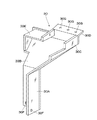
即ち、30は給脂管路28を保護する保護カバーで、該保護カバー30は、図4〜5等に示すように、給脂管路28のうちサイドフレーム14から露出した部位、即ち、サイドフレーム14の配管孔14C1から上方に突出すると共に台座22の側面に沿って上,下方向に配設された部位を覆うものである。このために、保護カバー30は、台座22の四隅に、該四隅をそれぞれ外側から覆う状態で、サイドフレーム14の上面板14Cの上面とスライダ23の下面との間に設けられている。   That is, 30 is a protective cover for protecting the greasing pipeline 28, and the protective cover 30 is a portion of the greasing pipeline 28 exposed from the side frame 14, that is, the side as shown in FIGS. It protrudes upward from the piping hole 14C1 of the frame 14 and covers a portion disposed upward and downward along the side surface of the pedestal 22. For this purpose, the protective cover 30 is provided at the four corners of the base 22 between the upper surface of the upper surface plate 14C of the side frame 14 and the lower surface of the slider 23 so as to cover the four corners from the outside.

ここで、保護カバー30は、図6等に示すように、横断面形状がL字状の下カバー部30Aと、該下カバー部30Aの上端縁に接続して設けられ該上端縁から上側に向かう程台座22から離れる方向に傾斜する傾斜部30Bと、該傾斜部30Bの上端縁に接続して設けられ横断面形状がL字状の上カバー部30Cと、該上カバー部30Cの上端縁に設けられスライダ23の下面に沿って傾斜するブラケット部30Dと、上カバー部30Cに設けられ該上カバー部30Cと台座22との間を上側から覆う覆部30Eとにより大略構成されている。   Here, as shown in FIG. 6 and the like, the protective cover 30 is provided so as to be connected to the lower cover portion 30A having an L-shaped cross section and the upper end edge of the lower cover portion 30A, and upward from the upper end edge. An inclined portion 30B that inclines in a direction away from the pedestal 22 as it goes, an upper cover portion 30C that is connected to the upper end edge of the inclined portion 30B and has an L-shaped cross section, and an upper end edge of the upper cover portion 30C The bracket portion 30D that is provided along the lower surface of the slider 23 and the cover portion 30E that is provided on the upper cover portion 30C and covers the space between the upper cover portion 30C and the pedestal 22 from the upper side.

下カバー部30Aの下端側には、該下カバー部30Aを台座22に設けられたブラケット22Aにボルト止めするための下側ボルト挿通孔30Fが設けられている。また、ブラケット部30Dには、該ブラケット部30Dをスライダ23の下面にボルト止めするための上側ボルト挿通孔30Gが設けられている。そして、保護カバー30は、下カバー部30Aを下側ボルト30Hを用いて台座22のブラケット22Aに固定すると共に、ブラケット部30Dを上側ボルト30Jを用いてスライダ23の下面に固定することにより、台座22の四隅に給脂管路28を覆った状態でそれぞれ取付けられている。   A lower bolt insertion hole 30 </ b> F for bolting the lower cover portion 30 </ b> A to a bracket 22 </ b> A provided on the base 22 is provided on the lower end side of the lower cover portion 30 </ b> A. The bracket portion 30D is provided with an upper bolt insertion hole 30G for bolting the bracket portion 30D to the lower surface of the slider 23. The protective cover 30 fixes the lower cover portion 30A to the bracket 22A of the pedestal 22 using the lower bolt 30H, and fixes the bracket portion 30D to the lower surface of the slider 23 using the upper bolt 30J. The greasing pipelines 28 are respectively attached to the four corners 22.

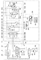
次に、走行用油圧モータ15の駆動と給脂装置24によるグリースの供給とを行う油圧回路について、図7を参照しつつ説明する。   Next, a hydraulic circuit for driving the traveling hydraulic motor 15 and supplying grease by the greasing device 24 will be described with reference to FIG.

図中、31は上部旋回体3に搭載された油圧ポンプとしてのメインポンプで、該メインポンプ31は、後述のパイロットポンプ44と共に、エンジン、電動モータ等の原動機(図示せず)によって回転駆動されることにより、作動油タンク32に貯溜された作動油を吐出し、走行用油圧モータ15を含む各種油圧アクチュエータを駆動するものである。   In the figure, 31 is a main pump as a hydraulic pump mounted on the upper swing body 3, and the main pump 31 is rotated and driven by a prime mover (not shown) such as an engine and an electric motor together with a pilot pump 44 described later. Thus, the hydraulic oil stored in the hydraulic oil tank 32 is discharged, and various hydraulic actuators including the traveling hydraulic motor 15 are driven.

走行用油圧モータ15は、メインポンプ31、作動油タンク32に主管路33A,33B等を介して接続され、メインポンプ31からの圧油の供給により回転駆動されるものである。ここで、走行用油圧モータ15は、斜板または斜軸等の容量可変部15Aを有する可変容量形の油圧モータにより構成され、例えばそのモータ容量が容量可変部15Aの傾転角に応じて可変に制御されるものである。   The traveling hydraulic motor 15 is connected to the main pump 31 and the hydraulic oil tank 32 via main pipelines 33A and 33B and is driven to rotate by the supply of pressure oil from the main pump 31. Here, the traveling hydraulic motor 15 is constituted by a variable displacement hydraulic motor having a displacement variable portion 15A such as a swash plate or a slant shaft, and the motor capacity is variable according to the tilt angle of the displacement variable portion 15A, for example. Are controlled by

そして、走行用油圧モータ15は、メインポンプ31からの圧油により、モータ容量が大容量のときは、高トルクで低速回転され、この場合には、例えば油圧ショベル1に十分な登坂力を与えることができ、油圧ショベル1の走行速度は相対的に遅い速度に設定される。一方、モータ容量が小容量のときは、メインポンプ31からの圧油により走行用油圧モータ15は低トルクで高速回転され、油圧ショベル1の走行速度を速くする。   The traveling hydraulic motor 15 is rotated at a low speed with a high torque when the motor capacity is large due to the pressure oil from the main pump 31. In this case, for example, the hydraulic excavator 1 is given a sufficient climbing force. The traveling speed of the excavator 1 is set to a relatively slow speed. On the other hand, when the motor capacity is small, the traveling hydraulic motor 15 is rotated at high speed with low torque by the pressure oil from the main pump 31, and the traveling speed of the excavator 1 is increased.

34は走行用油圧モータ15の容量を可変に制御する容量制御回路である。この容量制御回路34は、後述の傾転制御シリンダ35と、容量制御弁36とにより大略構成されている。   Reference numeral 34 denotes a capacity control circuit that variably controls the capacity of the traveling hydraulic motor 15. The capacity control circuit 34 is roughly composed of a tilt control cylinder 35 (described later) and a capacity control valve 36.

35は走行用油圧モータ15の容量可変部15Aを傾転駆動する傾転制御シリンダである。この傾転制御シリンダ35は、後述の容量制御弁36を介して主管路33Aまたは33Bからの圧油が給排されることにより、走行用油圧モータ15の容量可変部15Aを図7中の矢示A,B方向に傾転駆動するものである。   Reference numeral 35 denotes a tilt control cylinder that tilts and drives the capacity variable portion 15 </ b> A of the traveling hydraulic motor 15. The tilt control cylinder 35 feeds and discharges the pressure oil from the main pipe line 33A or 33B via a capacity control valve 36, which will be described later, so that the capacity variable portion 15A of the traveling hydraulic motor 15 is changed to an arrow in FIG. It is tilted in the directions indicated by A and B.

36は傾転制御シリンダ35への圧油の給排を制御する容量制御弁である。この容量制御弁36は、後述するパイロット管路43のパイロット圧(指令圧)Pに応じて大容量位置(A)と小容量位置(B)とに切換制御される。そして、容量制御弁36は、大容量位置(A)にある間は、走行用油圧モータ15の容量可変部15Aを傾転制御シリンダ35で矢示A方向に傾転駆動させ、これにより走行用油圧モータ15のモータ容量を大容量(低速)に設定する。一方、容量制御弁36は、小容量位置(B)に切換えられた場合には、容量可変部15Aを傾転制御シリンダ35で矢示B方向に傾転駆動させ、これにより走行用油圧モータ15の容量を小容量(高速)に設定する。   Reference numeral 36 denotes a capacity control valve that controls supply and discharge of pressure oil to the tilt control cylinder 35. The capacity control valve 36 is controlled to be switched between a large capacity position (A) and a small capacity position (B) in accordance with a pilot pressure (command pressure) P in a pilot line 43 described later. While the displacement control valve 36 is in the large displacement position (A), the displacement variable portion 15A of the traveling hydraulic motor 15 is tilted and driven in the direction indicated by the arrow A by the tilt control cylinder 35. The motor capacity of the hydraulic motor 15 is set to a large capacity (low speed). On the other hand, when the capacity control valve 36 is switched to the small capacity position (B), the capacity variable portion 15A is tilted in the direction indicated by the arrow B by the tilt control cylinder 35, whereby the travel hydraulic motor 15 is driven. Set the capacity to a small capacity (high speed).

37は主管路33A,33Bの途中に設けられた走行用の方向制御弁である。この方向制御弁37は、例えば油圧ショベル1のオペレータが操作する走行レバー37Aによって中立位置(イ)から切換位置(ロ),(ハ)に切換操作され、この切換位置(ロ),(ハ)で、走行用油圧モータ15の回転方向を、図7の矢示F,R方向に切換える。また、方向制御弁37は、中立位置(イ)に復帰すると、メインポンプ31から走行用油圧モータ15に向けて圧油が給排されるのを遮断し、走行用油圧モータ15を停止させるものである。   Reference numeral 37 denotes a traveling direction control valve provided in the middle of the main pipelines 33A and 33B. The direction control valve 37 is switched from the neutral position (A) to the switching positions (B) and (C) by, for example, a travel lever 37A operated by the operator of the excavator 1, and the switching positions (B) and (C). Thus, the rotation direction of the traveling hydraulic motor 15 is switched to the directions indicated by arrows F and R in FIG. Further, when the directional control valve 37 is returned to the neutral position (A), the supply of hydraulic oil from the main pump 31 toward the traveling hydraulic motor 15 is cut off, and the traveling hydraulic motor 15 is stopped. It is.

38は走行用油圧モータ15と方向制御弁37との間に位置して主管路33A,33Bの途中に設けられたブレーキ回路で、該ブレーキ回路38は、後述のカウンタバランス弁39、リリーフ弁40,41等から構成されている。そして、ブレーキ回路38は、方向制御弁37が中立位置(イ)に戻した時に、走行用油圧モータ15が慣性回転すると、リリーフ弁40,41のうち何れかが開弁して主管路33A,33Bのうち高圧側の圧油を低圧側にリリーフし、走行用油圧モータ15に制動力を与えるものである。   A brake circuit 38 is located between the traveling hydraulic motor 15 and the direction control valve 37 and is provided in the middle of the main pipelines 33A and 33B. The brake circuit 38 includes a counter balance valve 39 and a relief valve 40 which will be described later. , 41 and the like. When the traveling hydraulic motor 15 rotates inertially when the direction control valve 37 returns to the neutral position (A), the brake circuit 38 opens one of the relief valves 40 and 41 to open the main line 33A, In 33B, the pressure oil on the high pressure side is relieved to the low pressure side, and a braking force is applied to the traveling hydraulic motor 15.

39は走行用油圧モータ15と方向制御弁37との間に位置して主管路33A,33Bの途中に設けられたカウンタバランス弁で、該カウンタバランス弁39は、左,右両側に戻しばね39A,39Bが設けられ、方向制御弁37の切換操作時に、これに連動するように中立位置(イ)から切換位置(ロ),(ハ)へと戻しばね39A,39Bに抗して切換る構成となっている。   A counter balance valve 39 is provided between the traveling hydraulic motor 15 and the directional control valve 37 and is provided in the middle of the main pipelines 33A and 33B. The counter balance valve 39 is provided with a return spring 39A on both the left and right sides. , 39B are provided, and when the directional control valve 37 is switched, it is switched from the neutral position (A) to the switching positions (B), (C) against the return springs 39A, 39B so as to be interlocked therewith. It has become.

即ち、方向制御弁37が中立位置(イ)から切換位置(ロ),(ハ)に切換えられたときに、カウンタバランス弁39はメインポンプ31からの圧油がパイロット管路39C,39Dに導かれることにより、中立位置(イ)から左,右の切換位置(ロ),(ハ)に戻しばね39A,39Bに抗して切換えられるものである。そして、カウンタバランス弁39は、切換位置(ロ),(ハ)に切換ったときに、メインポンプ31からの圧油が走行用油圧モータ15に向けて給給されるのを許すと共に、メインポンプ31からの戻り油を作動油タンク32に側に排出させる。   That is, when the directional control valve 37 is switched from the neutral position (A) to the switching position (B), (C), the counter balance valve 39 guides the pressure oil from the main pump 31 to the pilot lines 39C, 39D. As a result, the position is switched from the neutral position (A) to the left and right switching positions (B) and (C) against the return springs 39A and 39B. The counter balance valve 39 allows the pressure oil from the main pump 31 to be supplied to the traveling hydraulic motor 15 when switching to the switching positions (B) and (C), The return oil from the pump 31 is discharged to the hydraulic oil tank 32 to the side.

また、方向制御弁37が中立位置(イ)に戻された時には、これに連動してカウンタバランス弁39も、戻しばね39A,39Bにより中立位置(イ)に戻される。そして、カウンタバランス弁39は、中立位置(イ)において、慣性回転中の走行用油圧モータ15から排出される戻り油が、作動油タンク32側に流出するのを遮断することにより、走行用油圧モータ15との間で主管路33Aまたは33B内にブレーキ圧を発生させ、このブレーキ圧によって走行用油圧モータ15に制動力を与えるものである。   When the directional control valve 37 is returned to the neutral position (A), the counter balance valve 39 is also returned to the neutral position (I) by the return springs 39A and 39B. Then, the counter balance valve 39 blocks the return oil discharged from the traveling hydraulic motor 15 during inertia rotation from flowing out to the hydraulic oil tank 32 side at the neutral position (A), so that the traveling hydraulic pressure is reduced. A brake pressure is generated in the main pipeline 33A or 33B with the motor 15, and a braking force is applied to the traveling hydraulic motor 15 by the brake pressure.

さらに、車両が坂道等を降坂するときには、降坂方向の慣性力が車両に作用することにより走行用油圧モータ15が慣性回転され、該走行用油圧モータ15がポンプ作用を行うことがある。そして、この場合にも、カウンタバランス弁39は中立位置(イ)に復帰し、走行用油圧モータ15との間で主管路33Aまたは33B内にブレーキ圧を発生させることにより、車両の逸走を防止するものである。   Further, when the vehicle descends on a slope or the like, the traveling hydraulic motor 15 may be rotated by inertia due to the inertial force in the downhill direction acting on the vehicle, and the traveling hydraulic motor 15 may perform a pumping action. Also in this case, the counter balance valve 39 returns to the neutral position (A), and the brake pressure is generated in the main line 33A or 33B with the traveling hydraulic motor 15, thereby preventing the vehicle from running away. To do.

40,41は走行用油圧モータ15とカウンタバランス弁39との間に位置して主管路33A,33B間に設けられた一対のリリーフ弁で、該リリーフ弁40,41は、走行用油圧モータ15の慣性回転時等に主管路33Aまたは33B内に発生したブレーキ圧がリリーフ設定圧よりも高い過剰圧になると開弁してこの過剰圧を相手方となる主管路33Bまたは33A側にリリーフさせる。そして、この間に、リリーフ弁40,41は、走行用油圧モータ15の慣性エネルギを吸収し、走行用油圧モータ15を徐々に停止させると共に、走行用油圧モータ15に過負荷が作用するのを防止するものである。   Reference numerals 40 and 41 denote a pair of relief valves which are located between the main hydraulic passages 33A and 33B and are located between the traveling hydraulic motor 15 and the counter balance valve 39. The relief valves 40 and 41 are connected to the traveling hydraulic motor 15 respectively. When the brake pressure generated in the main line 33A or 33B becomes an excess pressure higher than the relief set pressure during the inertia rotation, the valve is opened and the excess pressure is relieved to the other side of the main line 33B or 33A. During this time, the relief valves 40 and 41 absorb the inertia energy of the traveling hydraulic motor 15 to gradually stop the traveling hydraulic motor 15 and prevent an overload from acting on the traveling hydraulic motor 15. To do.

ここで、リリーフ弁40,41は、アキュムレータ付きのリリーフ弁として構成され、主管路33Aまたは33Bの圧力に対して段階的なリリーフ特性を有するものとしている。即ち、主管路33Aまたは33Bの圧力が高まるときに、リリーフ弁40または41の蓄油室40Aまたは41A内に絞り40B,41Bを介して圧油が供給されることにより、この蓄油室40Aまたは41A内に圧油が供給される間、リリーフ弁40または41の開弁圧を低圧にして、ブレーキ圧が急激に高まることによる急制動を防止できるようしている。   Here, the relief valves 40 and 41 are configured as a relief valve with an accumulator, and have a stepwise relief characteristic with respect to the pressure of the main pipeline 33A or 33B. That is, when the pressure in the main pipe line 33A or 33B increases, pressure oil is supplied into the oil storage chamber 40A or 41A of the relief valve 40 or 41 via the throttles 40B and 41B. While pressure oil is supplied into 41A, the valve opening pressure of the relief valve 40 or 41 is made low so that sudden braking due to sudden increase in brake pressure can be prevented.

42は走行用油圧モータ15の停止時に駆動輪16(走行用油圧モータ15)に制動力を付与するネガティブ型の駐車ブレーキである。この駐車ブレーキ42は、後述のパイロット管路43(43A)に接続され、該パイロット管路43(43A)のパイロット圧が所定のブレーキ解除圧を上回ると、ブレーキを解除して駆動輪16(走行用油圧モータ15)の回転を許すものである。   Reference numeral 42 denotes a negative parking brake that applies a braking force to the drive wheels 16 (travel hydraulic motor 15) when the travel hydraulic motor 15 is stopped. The parking brake 42 is connected to a pilot pipeline 43 (43A), which will be described later. When the pilot pressure in the pilot pipeline 43 (43A) exceeds a predetermined brake release pressure, the parking brake 42 is released and the drive wheel 16 (running) The hydraulic motor 15) is allowed to rotate.

43は容量制御回路34の容量制御と駐車ブレーキ42のブレーキ制御を行うパイロット管路で、該パイロット管路43は、一端側が後述の電磁切換弁45を介してパイロットポンプ44と作動油タンク32とに選択的に接続されるものである。また、パイロット管路43の他端側は、ブレーキ側分岐管43Aと容量制御側分岐管43Bとに途中で分岐され、ブレーキ側分岐管43Aが駐車ブレーキ42に、容量制御側分岐管43Bが容量制御弁36のパイロット室に、それぞれ接続されている。   Reference numeral 43 is a pilot line that performs capacity control of the capacity control circuit 34 and brake control of the parking brake 42. The pilot line 43 is connected to the pilot pump 44, the hydraulic oil tank 32, and the pilot line 43 via an electromagnetic switching valve 45 described later. Are selectively connected. Further, the other end side of the pilot pipe 43 is branched halfway into the brake side branch pipe 43A and the capacity control side branch pipe 43B, the brake side branch pipe 43A is the parking brake 42, and the capacity control side branch pipe 43B is the capacity. Each is connected to the pilot chamber of the control valve 36.

44は上部旋回体3に搭載されたパイロットポンプで、該パイロットポンプ44は、メインポンプ31と共に、エンジン、電動モータ等の原動機によって回転駆動されることにより、作動油タンク32に貯溜された作動油を吐出するものである。そして、パイロットポンプ44は、パイロット管路43(43A,43B)を介して容量制御弁36、駐車ブレーキ42、給脂装置24のグリース供給用油圧モータ27に接続されている。   Reference numeral 44 denotes a pilot pump mounted on the upper swing body 3. The pilot pump 44 is rotated together with a main pump 31 by a prime mover such as an engine or an electric motor, so that the hydraulic oil stored in the hydraulic oil tank 32 is stored. Is discharged. The pilot pump 44 is connected to the capacity control valve 36, the parking brake 42, and the grease supply hydraulic motor 27 of the greasing device 24 through a pilot line 43 (43 </ b> A, 43 </ b> B).

45はパイロット管路43の途中に設けられた電磁切換弁で、該電磁切換弁45は、例えば比例式電磁切換弁として構成され、その流入側にパイロットポンプ44、作動油タンク32が選択的に接続され、その流出側は、パイロット管路43(43A,43B)を介して容量制御弁36、駐車ブレーキ42、グリース供給用油圧モータ27に接続されている。そして、電磁切換弁45は、例えばコントロールユニット46からの制御信号に基づいて、パイロットポンプ44の吐出圧とタンク圧(0)との間で所定のパイロット圧(指令圧)Pを発生させるものである。   45 is an electromagnetic switching valve provided in the middle of the pilot pipe line 43. The electromagnetic switching valve 45 is configured as, for example, a proportional electromagnetic switching valve, and the pilot pump 44 and the hydraulic oil tank 32 are selectively provided on the inflow side thereof. The outlet side is connected to the capacity control valve 36, the parking brake 42, and the grease supply hydraulic motor 27 via a pilot line 43 (43A, 43B). The electromagnetic switching valve 45 generates a predetermined pilot pressure (command pressure) P between the discharge pressure of the pilot pump 44 and the tank pressure (0) based on a control signal from the control unit 46, for example. is there.

より具体的には、電磁切換弁45は、例えば、オペレータが切換操作する走行レバー37A(方向制御弁37)の位置と速度切換スイッチ47の位置とに対応して、所定のパイロット圧Pを発生させる(所定のパイロット圧Pに調節する)。この為に、例えば、コントロールユニット46の入力側には、走行レバー37Aが停止位置と走行位置との何れかであるかを検出する走行レバー用センサ48と、オペレータが切換操作することにより油圧ショベル1の走行速度を低速と高速との何れかに切換えるための速度切換スイッチ47とが接続されている。一方、コントロールユニット46の出力側は、電磁切換弁45と接続されている。   More specifically, the electromagnetic switching valve 45 generates a predetermined pilot pressure P corresponding to, for example, the position of the traveling lever 37A (direction control valve 37) that is switched by the operator and the position of the speed switching switch 47. (Adjust to a predetermined pilot pressure P). For this purpose, for example, on the input side of the control unit 46, a traveling lever sensor 48 that detects whether the traveling lever 37A is in the stop position or the traveling position, and a hydraulic excavator when the operator performs a switching operation. A speed changeover switch 47 for switching the traveling speed of 1 to either low speed or high speed is connected. On the other hand, the output side of the control unit 46 is connected to the electromagnetic switching valve 45.

そして、例えば走行レバー37Aが停止位置、即ち、方向制御弁37の位置が中立位置(イ)の場合は、電磁切換弁45は、パイロット圧Pを、駐車ブレーキ42の解除圧、容量制御弁36の切換圧、グリース供給用油圧モータ27の駆動開始圧の何れも下回る圧力、例えば0(タンク圧)にする。これにより、駐車ブレーキ42は作動し、グリース供給用油圧モータ27は駆動されず、容量制御弁36は大容量位置(A)となる。   For example, when the traveling lever 37A is in the stop position, that is, when the direction control valve 37 is in the neutral position (A), the electromagnetic switching valve 45 sets the pilot pressure P, the release pressure of the parking brake 42, and the capacity control valve 36. The pressure is lower than both the switching pressure and the drive start pressure of the grease supply hydraulic motor 27, for example, 0 (tank pressure). As a result, the parking brake 42 is operated, the grease supply hydraulic motor 27 is not driven, and the capacity control valve 36 is in the large capacity position (A).

一方、走行レバー37Aが中立位置から走行位置(例えば前進位置または後退位置)に操作された場合、即ち、方向制御弁37が切換位置(ロ),(ハ)に切換操作された場合は、電磁切換弁45は、パイロット圧Pを、少なくとも駐車ブレーキ42の解除圧とグリース供給用油圧モータ27の駆動圧との両方を上回る圧力にする。このとき、速度切換スイッチ47が低速位置であれば、電磁切換弁45は、パイロット圧Pを、駐車ブレーキ42の解除圧とグリース供給用油圧モータ27の駆動開始圧との両方を上回るが、容量制御弁36の切換圧は下回る圧力(例えば低圧)にする。   On the other hand, when the travel lever 37A is operated from the neutral position to the travel position (for example, the forward position or the reverse position), that is, when the direction control valve 37 is switched to the switching position (B) or (C), the electromagnetic The switching valve 45 sets the pilot pressure P to a pressure that exceeds at least both the release pressure of the parking brake 42 and the drive pressure of the grease supply hydraulic motor 27. At this time, if the speed changeover switch 47 is in the low speed position, the electromagnetic changeover valve 45 exceeds the pilot pressure P by both the release pressure of the parking brake 42 and the drive start pressure of the grease supply hydraulic motor 27. The switching pressure of the control valve 36 is set to a lower pressure (for example, a low pressure).

これにより、駐車ブレーキ42は解除され、グリース供給用油圧モータ27は駆動され、容量制御弁36は大容量位置(A)となる。このとき、グリース供給用油圧モータ27によりグリースポンプ26が回転駆動され、グリース貯溜タンク25に貯溜されたグリースは、給脂管路28、給脂孔29を通じてスライダ23の接触面23Aとトラックシュー19のスライダ接触面19Bとの間に供給される。これにより、スライダ23と履帯18(各トラックシュー19)との摺接部位が潤滑され、当該摺接部位の摩擦抵抗、摩耗を低減することができる。   As a result, the parking brake 42 is released, the grease supply hydraulic motor 27 is driven, and the capacity control valve 36 is in the large capacity position (A). At this time, the grease pump 26 is rotationally driven by the grease supply hydraulic motor 27, and the grease stored in the grease storage tank 25 passes through the greasing line 28 and the greasing hole 29 and the contact surface 23 </ b> A of the slider 23 and the track shoe 19. To the slider contact surface 19B. Thereby, the sliding contact part of the slider 23 and the crawler belt 18 (each track shoe 19) is lubricated, and the frictional resistance and wear of the sliding contact part can be reduced.

また、速度切換スイッチ47が高速位置に操作された場合は、電磁切換弁45は、パイロット圧Pを、駐車ブレーキ42の解除圧、グリース供給用油圧モータ27の駆動開始圧、容量制御弁36の切換圧の何れも上回る圧力(例えば高圧)にする。これにより、駐車ブレーキ42は解除され、グリース供給用油圧モータ27は駆動し、容量制御弁36は小容量位置(B)となる。このときも、グリース供給用油圧モータ27によりグリースポンプ26が回転駆動され、スライダ23と履帯18との摺接部位にグリースが供給されるから、当該摺接部位の摩擦抵抗、摩耗を低減することができる。   When the speed changeover switch 47 is operated to the high speed position, the electromagnetic changeover valve 45 sets the pilot pressure P, the release pressure of the parking brake 42, the drive start pressure of the grease supply hydraulic motor 27, and the capacity control valve 36. The pressure is higher than any of the switching pressures (for example, high pressure). As a result, the parking brake 42 is released, the grease supply hydraulic motor 27 is driven, and the capacity control valve 36 is in the small capacity position (B). Also at this time, since the grease pump 26 is rotationally driven by the grease supply hydraulic motor 27 and grease is supplied to the sliding contact portion between the slider 23 and the crawler belt 18, the frictional resistance and wear of the sliding contact portion are reduced. Can do.

なお、図中、一点鎖線で示す49は、上部旋回体3の旋回動作に拘わらず上部旋回体3と下部走行体11との間で作動油の流通を可能にするためのセンタジョイントである。また、50は、作動油タンク32に作動油を戻すための戻り管路(ドレン管路)である。   In the figure, 49 indicated by a one-dot chain line is a center joint for allowing the hydraulic oil to flow between the upper swing body 3 and the lower traveling body 11 regardless of the swing operation of the upper swing body 3. Reference numeral 50 denotes a return pipe (drain pipe) for returning the hydraulic oil to the hydraulic oil tank 32.

本実施の形態による油圧ショベル1は上述の如き構成を有するもので、次に、油圧ショベル1の下部走行体11で走行するときの動作について説明する。   The hydraulic excavator 1 according to the present embodiment has the above-described configuration. Next, the operation when the excavator 1 travels with the lower traveling body 11 will be described.

まず、オペレータが走行レバー37Aを操作することにより方向制御弁37を中立位置(イ)から切換位置(ロ)に切換操作すると、これに連動してカウンタバランス弁39が中立位置(イ)から切換位置(ロ)に切換る。そして、走行用油圧モータ15にはメインポンプ31からの圧油が主管路33Aを介して供給され、戻り油が主管路33Bを介して作動油タンク32へと排出される。これにより走行用油圧モータ15が矢示F方向に回転駆動され、下部走行体11が前進する。また、方向制御弁37を中立位置(イ)から切換位置(ハ)に切換えた時には、カウンタバランス弁39が切換位置(ハ)に切換えられ、走行用油圧モータ15が矢示R方向に回転駆動され、下部走行体11が後進する。   First, when the operator operates the travel lever 37A to switch the direction control valve 37 from the neutral position (A) to the switching position (B), the counter balance valve 39 is switched from the neutral position (A) in conjunction with this operation. Switch to position (b). The traveling hydraulic motor 15 is supplied with pressure oil from the main pump 31 via the main line 33A, and the return oil is discharged to the hydraulic oil tank 32 via the main line 33B. As a result, the traveling hydraulic motor 15 is rotationally driven in the direction of arrow F, and the lower traveling body 11 moves forward. When the direction control valve 37 is switched from the neutral position (A) to the switching position (C), the counter balance valve 39 is switched to the switching position (C), and the traveling hydraulic motor 15 is driven to rotate in the direction indicated by the arrow R. Then, the lower traveling body 11 moves backward.

この場合に、オペレータにより操作される速度切換スイッチ47が低速位置にあれば、パイロット管路43のパイロット圧Pは電磁切換弁45により低圧(駐車ブレーキ42の解除圧およびグリース供給用油圧モータ27の駆動開始圧を上回るが容量制御弁36の切換圧は下回る圧力)に調節され、容量制御回路34の容量制御弁36が大容量位置(A)に保持される。このため、走行用油圧モータ15の容量可変部15Aが傾転制御シリンダ35により矢示A方向に傾転駆動され、モータ容量が大容量に設定される。これにより、走行用油圧モータ15はメインポンプ31からのモータ駆動圧により高トルクで低速回転され、油圧ショベル1は十分なトルクをもって低速で走行駆動される。   In this case, if the speed changeover switch 47 operated by the operator is in the low speed position, the pilot pressure P in the pilot line 43 is reduced by the electromagnetic changeover valve 45 (the release pressure of the parking brake 42 and the grease supply hydraulic motor 27). The displacement control valve 36 of the displacement control circuit 34 is held at the large displacement position (A). For this reason, the displacement variable portion 15A of the traveling hydraulic motor 15 is tilted in the direction of arrow A by the tilt control cylinder 35, and the motor capacity is set to a large capacity. As a result, the traveling hydraulic motor 15 is rotated at a low speed with high torque by the motor driving pressure from the main pump 31, and the excavator 1 is driven to travel at a low speed with sufficient torque.

一方、速度切換スイッチ47が低速位置から高速位置に操作された場合は、パイロット管路43のパイロット圧Pは電磁切換弁45により高圧(駐車ブレーキ42の解除圧、グリース供給用油圧モータ27の駆動開始圧、容量制御弁36の切換圧を上回る圧力)に調節され、容量制御弁36が小容量位置(B)に切換る。このため、走行用油圧モータ15の容量可変部15Aが傾転制御シリンダ35により矢示B方向に傾転駆動され、モータ容量が小容量に設定される。これにより、走行用油圧モータ15はメインポンプ31からのモータ駆動圧により低トルクで高速回転され、油圧ショベル1を高速で走行駆動することができる。   On the other hand, when the speed changeover switch 47 is operated from the low speed position to the high speed position, the pilot pressure P in the pilot line 43 is increased by the electromagnetic switching valve 45 (the release pressure of the parking brake 42, the drive of the grease supply hydraulic motor 27). The starting pressure is adjusted to a pressure exceeding the switching pressure of the capacity control valve 36), and the capacity control valve 36 is switched to the small capacity position (B). Therefore, the displacement variable portion 15A of the traveling hydraulic motor 15 is tilted in the direction indicated by the arrow B by the tilt control cylinder 35, and the motor capacity is set to a small capacity. As a result, the traveling hydraulic motor 15 is rotated at high speed with low torque by the motor driving pressure from the main pump 31, and the hydraulic excavator 1 can be driven to travel at high speed.

何れにしても、油圧ショベル1の走行時は、走行用油圧モータ15により回転駆動される駆動輪16の噛合部16Aが各トラックシュー19の係合突起19Aに噛合うことにより、駆動輪16により履帯18を遊動輪17との間で周回動作させることができ、履帯18の周回動作によって下部走行体11を走行させることができる。また、履帯18を周回動作させているときには、各下ローラ21、各スライダ23が履帯18を周回方向に案内するが、このとき、履帯18を構成する各トラックシュー19のスライダ接触面19Bは、各スライダ23の接触面23Aと接触する(摺接)する。   In any case, when the hydraulic excavator 1 travels, the meshing portion 16A of the drive wheel 16 that is rotationally driven by the travel hydraulic motor 15 meshes with the engagement protrusion 19A of each track shoe 19, so that the drive wheel 16 The crawler belt 18 can be rotated around the idler wheel 17, and the lower traveling body 11 can be driven by the circular movement of the crawler belt 18. Further, when the crawler belt 18 is in a circling motion, the lower rollers 21 and the sliders 23 guide the crawler belt 18 in the circling direction. At this time, the slider contact surface 19B of each track shoe 19 constituting the crawler belt 18 is The slider 23 comes into contact (sliding contact) with the contact surface 23A.

この場合、本実施の形態によれば、スライダ23と履帯18との摺接部位にグリースを自動で供給する給脂装置24を設ける構成としているので、該給脂装置24によりスライダ23と履帯18との摺接部位を潤滑することができる。   In this case, according to the present embodiment, since the grease supplying device 24 for automatically supplying the grease to the sliding contact portion between the slider 23 and the crawler belt 18 is provided, the slider 23 and the crawler belt 18 are provided by the grease supplying device 24. The sliding contact portion can be lubricated.

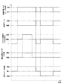
即ち、図8に示すように、オペレータが走行レバー37Aを中立位置から前進位置または後進位置に操作することにより、方向制御弁37が中立位置(イ)から切換位置(ロ)または(ハ)に切換えられると、パイロット管路43のパイロット圧Pは、電磁切換弁45により、駐車ブレーキ42の解除圧およびグリース供給用油圧モータ27の駆動開始圧よりも高い圧力(低圧または高圧)に調節される。   That is, as shown in FIG. 8, when the operator operates the traveling lever 37A from the neutral position to the forward position or the reverse position, the directional control valve 37 changes from the neutral position (A) to the switching position (B) or (C). When switched, the pilot pressure P in the pilot line 43 is adjusted to a pressure (low pressure or high pressure) higher than the release pressure of the parking brake 42 and the driving start pressure of the grease supply hydraulic motor 27 by the electromagnetic switching valve 45. .

これにより、駐車ブレーキ42が解除されると共に、グリース供給用油圧モータ27が駆動され、グリース貯溜タンク25に貯溜されたグリースが、給脂管路28、給脂孔29を通じてスライダ23の接触面23Aとトラックシュー19のスライダ接触面19Bとの間に供給される。そして、このように供給されるグリースにより、スライダ23と履帯18との摺接部位が潤滑され、当該摺接部位の摩擦抵抗、摩耗を低減することができる。この結果、スライダ23と履帯18の寿命(交換時期)を延ばすことができ、下部走行体11の耐久性、信頼性を高めることができる。   As a result, the parking brake 42 is released and the grease supply hydraulic motor 27 is driven so that the grease stored in the grease storage tank 25 passes through the greasing line 28 and the greasing hole 29 and contacts the contact surface 23A of the slider 23. And the slider contact surface 19B of the track shoe 19. And the sliding contact site | part of the slider 23 and the crawler belt 18 is lubricated by the grease supplied in this way, and the frictional resistance and abrasion of the said sliding contact site | part can be reduced. As a result, the lifetime (replacement time) of the slider 23 and the crawler belt 18 can be extended, and the durability and reliability of the lower traveling body 11 can be improved.

また、本実施の形態によれば、サイドフレーム14の上面板14Cとスライダ23の下面との間に、給脂装置24の給脂管路28を覆う保護カバー30を設ける構成としているので、給脂管路28に土砂が直接堆積することを保護カバー30により防止することができ、給脂装置24の耐久性、信頼性を高めることができる。   Further, according to the present embodiment, the protective cover 30 that covers the greasing pipeline 28 of the greasing device 24 is provided between the upper surface plate 14C of the side frame 14 and the lower surface of the slider 23. The protective cover 30 can prevent the earth and sand from directly depositing on the oil conduit 28, and the durability and reliability of the greasing device 24 can be improved.

更に、本実施の形態によれば、給脂装置24を構成するグリースポンプ26は、パイロット管路43のパイロット圧Pを動力として駆動されるグリース供給用油圧モータ27により駆動される構成としている。ここで、パイロット管路43のパイロット圧Pは、走行用油圧モータ15の容量を制御する容量制御回路34の容量制御と駐車ブレーキ42のブレーキ制御とを行うものであるので、下部走行体11の走行に合せて(下部走行体11の走行に伴って)、グリース供給用油圧モータ27によりグリースポンプ26を駆動することができる。これにより、スライダ23と履帯18との摺接部位を、下部走行体11の走行に応じて好適に潤滑することができ、この面からも、下部走行体11の耐久性、信頼性の向上を図ることができる。   Further, according to the present embodiment, the grease pump 26 constituting the grease supplying device 24 is driven by the grease supply hydraulic motor 27 driven by the pilot pressure P of the pilot pipe 43. Here, the pilot pressure P in the pilot line 43 is for performing the capacity control of the capacity control circuit 34 that controls the capacity of the traveling hydraulic motor 15 and the brake control of the parking brake 42. The grease pump 26 can be driven by the grease supply hydraulic motor 27 in accordance with the traveling (with the traveling of the lower traveling body 11). Thereby, the sliding contact portion between the slider 23 and the crawler belt 18 can be suitably lubricated according to the traveling of the lower traveling body 11, and also from this aspect, the durability and reliability of the lower traveling body 11 can be improved. Can be planned.

なお、上述した実施の形態では、サイドフレーム14の長さ方向中間部の台座22に支持されたスライダ23に給脂孔29を設けた場合を例に挙げて説明した。しかし、本発明はこれに限らず、例えば、サイドフレームに台座を介して支持された全てのスライダに給脂孔を設ける構成としてもよい。   In the embodiment described above, the case where the greasing hole 29 is provided in the slider 23 supported by the pedestal 22 at the intermediate portion in the longitudinal direction of the side frame 14 has been described as an example. However, the present invention is not limited to this, and for example, a configuration may be adopted in which greasing holes are provided in all the sliders supported on the side frames via the pedestals.

また、上述した実施の形態では、パイロット管路43は、走行用油圧モータ15の容量制御と駐車ブレーキ42のブレーキ制御との両方を同じパイロット管路43を用いて行う場合を例に挙げて説明した。しかし、本発明はこれに限らず、例えば、走行用油圧モータの容量制御と駐車ブレーキのブレーキ制御とをそれぞれ別のパイロット管路を用いて行う構成としてもよい。この場合、給脂装置の給脂ポンプは、例えば駐車ブレーキのブレーキ制御を行うパイロット管路のパイロット圧を動力として駆動させることができる。   Further, in the above-described embodiment, the pilot pipe line 43 is described by taking as an example a case where both the capacity control of the traveling hydraulic motor 15 and the brake control of the parking brake 42 are performed using the same pilot pipe line 43. did. However, the present invention is not limited to this. For example, the displacement control of the traveling hydraulic motor and the brake control of the parking brake may be performed using different pilot pipelines. In this case, the greasing pump of the greasing device can be driven using, for example, the pilot pressure of the pilot line that performs brake control of the parking brake as power.

更に、上述した実施の形態では、装軌式車両の走行体として油圧ショベル1の下部走行体11を例示している。しかし、本発明はこれに限るものではなく、例えば油圧クレーン、ブルドーザ等の他の装軌式車両の走行体にも広く適用することができる。   Furthermore, in embodiment mentioned above, the lower traveling body 11 of the hydraulic shovel 1 is illustrated as a traveling body of a tracked vehicle. However, the present invention is not limited to this, and can be widely applied to traveling bodies of other tracked vehicles such as a hydraulic crane and a bulldozer.

1 油圧ショベル(装軌式車両)
11 下部走行体(走行体)
12 トラックフレーム
13 センタフレーム
14 サイドフレーム
15 走行用油圧モータ(油圧モータ)
16 駆動輪
17 遊動輪
18 履帯
23 スライダ
24 給脂装置
25 グリース貯溜タンク(貯油タンク)
26 グリースポンプ(給脂ポンプ)
28 給脂管路
29 給脂孔
30 保護カバー
31 メインポンプ(油圧ポンプ)
33A,33B 主管路
34 容量制御回路
37 方向制御弁
42 駐車ブレーキ
43 パイロット管路
1 Hydraulic excavator (tracked vehicle)
11 Lower traveling body (traveling body)
12 Track frame 13 Center frame 14 Side frame 15 Traveling hydraulic motor (hydraulic motor)
16 Drive Wheel 17 Idle Wheel 18 Crawler Track 23 Slider 24 Greasing Device 25 Grease Storage Tank (Oil Storage Tank)
26 Grease pump (Grease pump)
28 Greasing pipeline 29 Greasing hole 30 Protective cover 31 Main pump (hydraulic pump)
33A, 33B Main pipeline 34 Capacity control circuit 37 Directional control valve 42 Parking brake 43 Pilot pipeline

Claims (3)

センタフレームと該センタフレームの左,右両側で前,後方向に延びたサイドフレームとを有するトラックフレームと、該トラックフレームの各サイドフレームの長さ方向の一側に設けられた駆動輪と、前記各サイドフレームの長さ方向の他側に設けられた遊動輪と、前記駆動輪と遊動輪とに巻回して設けられた履帯と、前記各サイドフレームに設けられ前記駆動輪と遊動輪との間で前記履帯を案内するスライダとを備えてなる装軌式車両の走行体において、
前記スライダと前記履帯との摺接部位に潤滑油を自動で供給する給脂装置を設ける構成としたことを特徴とする装軌式車両の走行体。
A track frame having a center frame and side frames extending in the front and rear directions on both the left and right sides of the center frame; and a drive wheel provided on one side in the length direction of each side frame of the track frame; An idler wheel provided on the other side in the length direction of each side frame, a crawler belt wound around the drive wheel and the idler wheel, and the drive wheel and idler wheel provided in each side frame; In a tracked vehicle traveling body comprising a slider for guiding the crawler belt between,
A tracked vehicle traveling body characterized in that a lubrication device for automatically supplying lubricating oil to a sliding contact portion between the slider and the crawler belt is provided.
前記給脂装置は、前記摺接部位に対応して前記スライダに設けられた給脂孔と、該給脂孔に前記潤滑油を導く給脂管路とを有し、前記サイドフレームには、前記給脂管路のうち該サイドフレームから露出した部位を覆う保護カバーを設ける構成としてなる請求項1に記載の装軌式車両の走行体。   The greasing device has a greasing hole provided in the slider corresponding to the sliding contact portion, and a greasing conduit for guiding the lubricating oil to the greasing hole, The traveling body of a tracked vehicle according to claim 1, wherein a protective cover is provided to cover a portion exposed from the side frame in the greasing pipeline. 油圧ポンプと、該油圧ポンプに主管路を介して接続され前記駆動輪を回転駆動する可変容量形の油圧モータと、該油圧モータの容量を可変に制御する容量制御回路と、前記主管路の途中に設けられる方向制御弁と、前記油圧モータの停止時に前記駆動輪に制動力を付与する駐車ブレーキと、前記容量制御回路の容量制御および/または前記駐車ブレーキのブレーキ制御を行うパイロット管路とを備え、
前記給脂装置は、前記潤滑油を貯溜する貯油タンクと、該貯油タンク内に貯溜された潤滑油を吐出する給脂ポンプとを有し、該給脂ポンプは、前記パイロット管路のパイロット圧を動力として前記潤滑油を吐出する構成としてなる請求項1または2に記載の装軌式車両の走行体。
A hydraulic pump, a variable displacement hydraulic motor connected to the hydraulic pump via a main line and rotationally driving the drive wheel, a capacity control circuit for variably controlling the capacity of the hydraulic motor, and a middle of the main line A direction control valve provided in the vehicle, a parking brake that applies a braking force to the drive wheel when the hydraulic motor is stopped, and a pilot pipe that performs capacity control of the capacity control circuit and / or brake control of the parking brake. Prepared,
The greasing device includes an oil storage tank that stores the lubricating oil, and a greasing pump that discharges the lubricating oil stored in the oil storage tank, and the greasing pump includes a pilot pressure of the pilot line. The traveling body of the tracked vehicle according to claim 1, wherein the lubricating oil is discharged using the power as a power source.
JP2011003835A 2011-01-12 2011-01-12 Traveling body of tracklaying vehicle Pending JP2012144141A (en)

Priority Applications (1)

Application Number Priority Date Filing Date Title
JP2011003835A JP2012144141A (en) 2011-01-12 2011-01-12 Traveling body of tracklaying vehicle

Applications Claiming Priority (1)

Application Number Priority Date Filing Date Title
JP2011003835A JP2012144141A (en) 2011-01-12 2011-01-12 Traveling body of tracklaying vehicle

Publications (1)

Publication Number Publication Date
JP2012144141A true JP2012144141A (en) 2012-08-02

Family

ID=46788189

Family Applications (1)

Application Number Title Priority Date Filing Date
JP2011003835A Pending JP2012144141A (en) 2011-01-12 2011-01-12 Traveling body of tracklaying vehicle

Country Status (1)

Country Link
JP (1) JP2012144141A (en)

Cited By (5)

* Cited by examiner, † Cited by third party
Publication number Priority date Publication date Assignee Title
WO2014182216A1 (en) * 2013-05-08 2014-11-13 BAE Systems Hägglunds Aktiebolag Drive unit for tracked vehicle and vehicle provided with drive unit
JP2016148446A (en) * 2015-02-06 2016-08-18 株式会社クボタ Working machine hydraulic system and working machine
US10316493B2 (en) 2015-02-06 2019-06-11 Kubota Corporation Hydraulic system and working machine including the same
US10543876B2 (en) 2016-12-15 2020-01-28 Caterpillar Inc. Track support rail for supporting track assembly of machine, track support assembly, and method of using same
US10562574B2 (en) 2016-09-08 2020-02-18 Caterpillar Inc. Slider for track assembly of machine

Cited By (7)

* Cited by examiner, † Cited by third party
Publication number Priority date Publication date Assignee Title
WO2014182216A1 (en) * 2013-05-08 2014-11-13 BAE Systems Hägglunds Aktiebolag Drive unit for tracked vehicle and vehicle provided with drive unit
EP2994371A4 (en) * 2013-05-08 2017-01-04 Bae Systems Hägglunds Aktiebolag Drive unit for tracked vehicle and vehicle provided with drive unit
US9878748B2 (en) 2013-05-08 2018-01-30 BAE Systems Hägglunds Aktiebolag Drive unit for tracked vehicle and vehicle provided with drive unit
JP2016148446A (en) * 2015-02-06 2016-08-18 株式会社クボタ Working machine hydraulic system and working machine
US10316493B2 (en) 2015-02-06 2019-06-11 Kubota Corporation Hydraulic system and working machine including the same
US10562574B2 (en) 2016-09-08 2020-02-18 Caterpillar Inc. Slider for track assembly of machine
US10543876B2 (en) 2016-12-15 2020-01-28 Caterpillar Inc. Track support rail for supporting track assembly of machine, track support assembly, and method of using same

Similar Documents

Publication Publication Date Title
JP5669692B2 (en) Working machine
JP2012144141A (en) Traveling body of tracklaying vehicle
CA2871244C (en) Guide rail for crawler track
JP5513395B2 (en) Combiner valve control system and method
JP5687970B2 (en) Working machine
JP6927686B2 (en) Flood control system with automatic ride control
JP2004205019A (en) Backhoe hydraulic circuit structure
CN103261536A (en) Closed loop drive circuit with external brake assist
JP2006336844A (en) Working machine
CN102758805A (en) Hydraulic circuit and working machine including the same
JP2006336846A (en) Fluid pressure circuit
JP5226569B2 (en) Working machine
JP2012162878A (en) Hydraulic drive unit of construction machine
WO2012039600A1 (en) Drive means for amphibious equipment
JP2006161510A (en) Backhoe hydraulic circuit structure
KR20080105709A (en) Running motor overspeed prevention device of crawler excavator
JP6618495B2 (en) Hydraulic drive
JP4746638B2 (en) Crawler type traveling device
JP5286156B2 (en) Working machine
JP5687971B2 (en) Working machine
JP4970357B2 (en) Hydraulic drive motor device
CN210526816U (en) Sea water drive deep sea tracked vehicle chassis
JP4797032B2 (en) Crawler type traveling device
JP4502890B2 (en) Backhoe hydraulic circuit structure
JP2000304129A (en) Working vehicle