JP2012144132A - Device for supporting rack shaft and steering device for vehicle - Google Patents
Device for supporting rack shaft and steering device for vehicle Download PDFInfo
- Publication number
- JP2012144132A JP2012144132A JP2011003345A JP2011003345A JP2012144132A JP 2012144132 A JP2012144132 A JP 2012144132A JP 2011003345 A JP2011003345 A JP 2011003345A JP 2011003345 A JP2011003345 A JP 2011003345A JP 2012144132 A JP2012144132 A JP 2012144132A
- Authority
- JP
- Japan
- Prior art keywords
- rack
- rack shaft
- bush
- metal case
- axial direction
- Prior art date
- Legal status (The legal status is an assumption and is not a legal conclusion. Google has not performed a legal analysis and makes no representation as to the accuracy of the status listed.)
- Pending
Links
Images


Landscapes
- Transmission Devices (AREA)
Abstract
Description
本発明はラック軸支持装置および車両用操舵装置に関する。 The present invention relates to a rack shaft support device and a vehicle steering device.
一般に、ラックアンドピニオン式の車両用操舵装置では、ラック軸が挿通するハウジングに嵌合された金属製のラックストッパによって、ラック軸の軸方向の移動量を規制している。また、ラックストッパよりもハウジングの軸方向内方位置で、ハウジングに嵌合された合成樹脂製のラックブッシュによって、ラック軸を軸方向に摺動可能に支持している。 In general, in a rack and pinion type vehicle steering apparatus, the amount of movement of the rack shaft in the axial direction is regulated by a metal rack stopper fitted in a housing through which the rack shaft is inserted. Further, the rack shaft is supported so as to be slidable in the axial direction by a synthetic resin rack bush fitted to the housing at a position axially inward of the housing relative to the rack stopper.
特許文献1では、ラックブッシュの一端に形成された環状フランジを、ハウジングの内周の位置決め段部に当接させて、ラックブッシュの軸方向移動が実質的に規制されている。また、ラックブッシュに軸方向に延びる複数のスリットが形成され、弾性的に縮径可能とされている。ラックブッシュの外周の軸方向中央部に設けられた周溝に、Oリングが収容され、このOリングによって、ラックブッシュが径方向に弾性支持されている。Oリングの締め付け力によって弾性的に縮径されたラックブッシュの内周とラック軸との径方向隙間が実質的にゼロにされている。
In
通常走行時は、ラック軸から付与されるラックブッシュへのラジアル荷重が小さいので、Oリングによって径方向に弾性支持されたラックブッシュの外周とハウジングの内周との間には、径方向隙間が存在している。すなわち、この径方向隙間の範囲内で、ラック軸を径方向に弾性支持し、ガタ等の異音の発生を防止している。
一方、タイヤ側からの逆入力によって、ラック軸から付与されるラックブッシュへのラジアル荷重が大きくなると、ラックブッシュが径方向に変位し、ラックブッシュの外周がハウジングの内周と接触する。これにより、ラック軸の撓みが抑制され、ラック軸の支持剛性が維持される。
During normal running, the radial load applied to the rack bush from the rack shaft is small, so there is a radial clearance between the outer periphery of the rack bush that is elastically supported in the radial direction by the O-ring and the inner periphery of the housing. Existing. In other words, the rack shaft is elastically supported in the radial direction within the range of the radial gap to prevent the generation of noise such as looseness.
On the other hand, when the radial load applied to the rack bush from the rack shaft increases due to reverse input from the tire side, the rack bush is displaced in the radial direction, and the outer periphery of the rack bush comes into contact with the inner periphery of the housing. Thereby, the deflection of the rack shaft is suppressed, and the support rigidity of the rack shaft is maintained.
上記のようなラックブッシュを用いている場合、ハンドルの切り始めの微小舵角領域において、ラックブッシュの内周とラック軸の外周との間の静止摩擦力の影響で、ラック軸の軸方向への始動が遅れる。すなわち、ラック軸に対して上記静止摩擦力を上回る軸方向の力が与えられて始めて、ラック軸が動き出すことになる。したがって、操舵開始時に、運転者が、引っ掛かるような操舵フィーリングを感じるという問題があった。 When the rack bush as described above is used, in the minute rudder angle region at the beginning of the turning of the handle, due to the influence of the static frictional force between the inner periphery of the rack bush and the outer periphery of the rack shaft, Is delayed. That is, the rack shaft starts to move only when an axial force exceeding the static friction force is applied to the rack shaft. Therefore, there is a problem that the driver feels a steering feeling that is caught at the start of steering.
本発明は上記課題に鑑みてなされたものであり、本発明の目的は、異音発生を抑制でき、且つ操舵開始時の引っ掛かり感を失くして操舵フィーリングを向上することができるラック軸支持装置および車両用操舵装置を提供することである。 The present invention has been made in view of the above problems, and an object of the present invention is to support a rack shaft that can suppress the generation of abnormal noise and can improve the steering feeling by losing the feeling of being caught at the start of steering. An apparatus and a vehicle steering device are provided.
上記目的を達成するため、請求項1の発明は、操舵に伴って軸方向(X1)に移動するラック軸(8)が挿通されたハウジング(9)と、上記ハウジング内に配置され、上記ラック軸を軸方向に摺動可能に支持する弾性的に縮径可能なラックブッシュ(18)と、上記ハウジング内に配置され、上記ラックブッシュを支持する第1および第2の環状弾性部材(19,20)と、を備え、上記第1および第2の環状弾性部材は、上記ハウジングによって直接または介在部材(17)を介して間接的に支持され、上記第1および第2の環状弾性部材は、それぞれ、上記ラックブッシュの第1および第2の端部(181,182)を径方向(R1)および軸方向に弾性支持し、上記ラック軸の軸方向移動の開始初期に、上記ラック軸および上記ラックブッシュの間の静止摩擦荷重(F2)によって、上記ラックブッシュが上記ラック軸と軸方向に同行移動するように構成されているラック軸支持装置(10;10A)を提供する。
In order to achieve the above object, the invention of
また、請求項2のように、各環状摩擦部材のセット荷重(F1)が、上記ラックブッシュおよび上記ラック軸間の上記静止摩擦荷重よりも小さくされている場合がある。
また、請求項3のように、上記介在部材は、上記ハウジングの内周に形成された保持部に圧入された金属ケース(17)であり、上記金属ケース内に、上記ラックブッシュとしての樹脂製のブッシュ(18)が収容されて、上記金属ケースおよび上記ラックブッシュを含むサブアセンブリ(SA)が構成されている場合がある。
In some cases, the set load (F1) of each annular friction member may be smaller than the static friction load between the rack bush and the rack shaft.
According to a third aspect of the present invention, the interposition member is a metal case (17) press-fitted into a holding portion formed on the inner periphery of the housing, and the resin case as the rack bush is formed in the metal case. The sub-assembly (SA) including the metal case and the rack bush may be configured.
また、請求項4のように、上記ラックブッシュの外周(18a)に、抜脱防止突起(30)が形成され、上記金属ケースの内周(23a)に、上記抜脱防止突起が挿入された環状の係合溝(24)が形成され、上記抜脱防止突起が上記係合溝に係合することにより、上記金属ケースから上記ラックブッシュの抜脱が防止されている場合がある。
また、請求項5のように、上記第1および第2の環状弾性部材のそれぞれは、Oリング(19,20)であり、上記ラックブッシュの上記第1および第1の端部の外周肩部(18b,18c)に、各Oリングを収容する環状溝(28,29)が、互いに軸方向の逆向きに開放するように形成されている場合がある。
Further, as in
According to a fifth aspect of the present invention, each of the first and second annular elastic members is an O-ring (19, 20), and an outer peripheral shoulder portion of the first and first ends of the rack bush. In (18b, 18c), the annular grooves (28, 29) for accommodating the O-rings may be formed so as to open in opposite directions in the axial direction.
また、請求項6の発明は、上記ラック軸支持装置を備える車両用操舵装置を提供する。 なお、上記において、括弧内の数字等は、後述する実施形態における対応構成要素の参照符号を表すものであるが、これらの参照符号により特許請求の範囲を限定する趣旨ではない。 According to a sixth aspect of the present invention, there is provided a vehicle steering apparatus including the rack shaft support device. In addition, in the above, the numbers in parentheses represent reference numerals of corresponding components in the embodiments described later, but the scope of the claims is not limited by these reference numerals.
請求項1の発明によれば、操舵に伴ってラック軸が軸方向に移動するときに、まず、対応する方向の環状弾性部材を弾性圧縮させて、ラックブッシュがラック軸と微小ストロークの間、同行移動し、その後、ラック軸がラックブッシュに対して摺動することになる。したがって、ラック軸とラックブッシュとの間の静止摩擦力よりも小さな荷重で、ラック軸を始動させることができるので、ハンドルの切り始めの操作トルクを非常に小さくすることができる。ひいては、操舵フィーリングとして、従来生じていた引っ掛かるような感じを失くすことができる。
According to the invention of
請求項2の発明によれば、各環状摩擦部材のセット荷重を、ラックブッシュおよびラック軸間の静止摩擦荷重よりも小さくすることにより、ハンドルの切り始めの操作トルクを非常に小さくすることが実質的に可能となる。
請求項3の発明によれば、金属ケース内に、ラックブッシュとしての樹脂製のブッシュを収容することにより、金属ケースおよびラックブッシュをサブアセンブリとして構成しているので、車両への組付け性が格段に向上する。
According to the second aspect of the present invention, the operation torque at the start of turning the steering wheel is substantially reduced by making the set load of each annular friction member smaller than the static friction load between the rack bush and the rack shaft. Is possible.
According to the invention of
請求項4の発明によれば、ラックブッシュの外周の突起が、金属ケースの内周の係合溝に係合することにより、金属ケースからラックブッシュの抜脱を確実に防止することができる。
請求項5の発明によれば、ラックブッシュの一対の端部の外周肩部にそれぞれ形成された一対の環状溝に、それぞれ、環状弾性部材としてOリングを収容することにより、簡単な構成で、コスト安価に、ラックブッシュを軸方向および径方向に弾性支持することができる。
According to the fourth aspect of the present invention, the protrusion on the outer periphery of the rack bush engages with the engagement groove on the inner periphery of the metal case, so that the rack bush can be reliably prevented from being detached from the metal case.
According to the invention of
請求項6の発明によれば、操舵フィーリングに優れた車両用操舵装置を実現することができる。
According to the invention of
本発明の好ましい実施の形態を添付図面を参照しつつ説明する。
図1は本発明の一実施の形態に係るラック軸支持装置が適用された車両用操舵装置1の概略構成を示す模式図である。図1を参照して、車両用操舵装置1は、ステアリングホイール等の操舵部材2に連結しているステアリングシャフト3と、ステアリングシャフト3に第1の自在継手4を介して連結された中間軸5と、中間軸5に第2の自在継手6を介して連結されたピニオン軸7と、ピニオン軸7の端部近傍に設けられたピニオン7aに噛み合うラック8aを有して自動車の左右方向に延びる転舵軸としてのラック軸8とを有している。ピニオン軸7およびラック軸8によりラックアンドピニオン機構からなる転舵機構Aが構成されている。
Preferred embodiments of the present invention will be described with reference to the accompanying drawings.
FIG. 1 is a schematic diagram showing a schematic configuration of a
ラック軸8は、車体に固定されるハウジング9内に、軸方向X1(車両の幅方向に相当)に沿って直線往復動可能に支持されている。ハウジング9は、第1の端部91と第2の端部92とを有しており、第1の端部91は、ピニオン7aから相対的に遠く、第2のピニオン7aに相対的に近い。本実施の形態に係るラック軸支持装置10は、ハウジング9の第1の端部91に配置され、ラック軸8を軸方向X1に移動可能に支持している。
The
本実施の形態では、上記ラック軸支持装置10が、ハウジング9の第1の端部91のみに配置された例に則して説明するが、上記ラック軸支持装置10が、ハウジング9の第1の端部91および第2の端部92の双方に配置されていてもよい。
ラック軸8の両端部はハウジング9の両側へ突出し、各端部にはそれぞれ継手11を介してタイロッド12が結合されている。各タイロッド12は対応するナックルアーム(図示せず)を介して対応する転舵輪13に連結されている。
In the present embodiment, the rack
Both end portions of the
操舵部材2が操作されてステアリングシャフト3が回転されると、この回転がピニオン7aおよびラック8aによって、自動車の左右方向に沿ってのラック軸8の直線運動に変換される。これにより、転舵輪13の転舵が達成される。
図1には示していないが、ハウジング9の軸方向の途中部には、ラック8aおよびピニオン7aの噛み合い部のバックラッシを除去するために、ラック軸8をピニオン軸7側へ弾性的に付勢するバックラッシ除去機構が設けられている。図2に示すように、バックラッシ除去機構14は、例えば図2に示すように、ラック軸8を軸方向X1に摺動可能に支持するサポートヨーク15と、サポートヨーク15を介してラック軸8をピニオン軸7側へ付勢する弾性部材16とを備えている。
When the
Although not shown in FIG. 1, in the middle of the
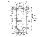
図3に示すように、ラック軸支持装置10は、ハウジング9の内周9aに圧入により保持された介在部材としての環状の金属ケース17と、金属ケース17内に収容され、ラック軸8を軸方向に摺動可能に支持する合成樹脂製の環状のラックブッシュ18と、金属ケース17内において、ラックブッシュ18の一対の外周肩部をそれぞれ弾性支持する環状弾性部材としての第1のOリング19および第2のOリング20とを備えている。各Oリング19,20は、ラックブッシュ18を軸方向X1および径方向R1に弾性支持している。
As shown in FIG. 3, the rack
図4に示すように、金属ケース17、ラックブッシュ18および両Oリング19,20がユニット化されてサブアセンブリSAを構成している。金属ケース17は、環状の本体21と、本体21の軸方向の一対の端部からそれぞれ径方向内方へ突出する一対の環状の端壁22とを有している。金属ケース17の内周17bには、本体21と一対の端壁22とによって区画されて、ラックブッシュ18を収容するための環状の内周凹部23が設けられている。
As shown in FIG. 4, the
金属ケース17の軸方向の中央部において、内周凹部23の底23aには、環状の係合溝24が形成されている。内周凹部23の第1および第2の内隅部23b,23cのそれぞれと、ラックブッシュ18の対応する外周肩部18b,18cとの間に、それぞれ対応するOリング19,20が収容されるように構成されている。
図3に示すように、ハウジング9の内周9aに形成された嵌合部9bに、金属ケース17の外周17a(本体21の外周に相当)が圧入されている。また、ハウジング9の内周9aには、位置決め段部25が設けられている。金属ケース17の第1の端面171が、位置決め段部25に当接することにより、ハウジング9に対する金属ケース17の軸方向移動が規制されている。
An
As shown in FIG. 3, the
嵌合部9bには、軸方向に関して金属ケース17の外周17aの一部のみが圧入されるようにされている。これにより、嵌合長を必要最小限として、ハウジング9への負荷を軽減し、ハウジング9の耐久性を向上している。
金属ケース17は、例えばアルミニウム合金製であり、ラックストッパとして機能する。すなわち、ラック軸8が最大ストロークしたときに、金属ケース17の第2の端面172が、ラック軸8とタイロッド12を連結する継手11(図1参照)の一部に当接することにより、ラック軸8の軸方向移動量を規制する。
Only a part of the
The
図4、図5、および図5のVI−VI線に沿う断面図である図6に示すように、ラックブッシュ18は、軸方向X1の第1および第2の端部181,182から、交互の逆向きに軸方向X1の途中部まで延びる第1のスリット26および第2のスリット27を有している。図4および図6に示すように、ラックブッシュ18の外周18aの第1および第2の外周肩部18b,18cには、それぞれ対応するOリング19,20の一部を収容する第1および第2の環状溝28,29が設けられている。
As shown in FIG. 6, which is a cross-sectional view taken along line VI-VI in FIGS. 4, 5, and 5, the
図4に示すように、ラックブッシュ18の第1および第2の環状溝28,29は、それぞれ、金属ケース17の内周凹部23の第1および第2の内隅部23b,23cに対向している。第1の環状溝28と第1の内隅部23bの間に、第1のOリング19が弾性的に圧縮された状態で収容されている。また、第2の環状溝29と第2の内隅部23cとの間に、第2のOリング20が弾性的に圧縮された状態で収容されている。
As shown in FIG. 4, the first and second
各Oリング19,20の弾性収縮力によって、第1および第2のスリット26,27を有するラックブッシュ18が弾性的に縮径されている。これにより、ラックブッシュ18の内周18dが、ラック軸8の外周8bに隙間無く接触している。
ラック軸8側からラックブッシュ18に負荷されるラジアル荷重が小さいときには、ラックブッシュ18の外周18aと金属ケース17の内周凹部23の底23aとの間に、隙間S1が設けられている。したがって、上記ラジアル荷重が小さいときには、ラックブッシュ18が、両Oリング19,20によって、径方向R1に弾性支持されている。
The
When the radial load applied to the
また、ラック軸8が軸方向X1への始動の初期には、ラックブッシュ18の第1の端部181および第2の端部182と金属ケース17の対応する端壁22との間には、隙間S2が設けられている。したがって、上記始動の初期には、ラックブッシュ18が、両Oリング19,20によって、軸方向X1に弾性支持されている。
図5に示すように、ラックブッシュ18の外周18aには、周方向に等間隔をあけて、複数の抜脱防止突起30が設けられている。各抜脱防止突起30は、図4に示すように、金属ケース17の内周としての内周凹部23の底23aに形成された係合溝24内に挿入されている。各抜脱防止突起30が、係合溝24に係合することにより、金属ケース17からのラックブッシュ18の軸方向X1への抜脱が防止されている。これにより、各Oリング19,20が金属ケース17から軸方向X1へ抜脱することが防止されている。
In addition, at the beginning of the start of the
As shown in FIG. 5, a plurality of
図示していないが、サブアセンブリSAを組み立てるときには、両Oリング19,20を装着したラックブッシュ18を、一旦大きく縮径させて、金属ケース17の軸方向X1から内周凹部23内に収容した後、ラックブッシュ18の弾性反発力で、抜脱防止突起30を係合溝24内に係合させるようにしている。
本実施の形態の特徴とするところは、ラック軸8の軸方向X1の移動の開始初期に、ラック軸8およびラックブッシュ18の間の静止摩擦力によって、ラックブッシュ18がラック軸8と軸方向X1に同行移動するように構成されている点にある。
Although not shown, when assembling the subassembly SA, the
The feature of this embodiment is that, at the beginning of the movement of the
具体的には、各Oリング19,20のセット荷重F1が、ラックブッシュ18およびラック軸8間の静止摩擦荷重F2よりも小さくされている(F1<F2)ことにより、ラック軸8の移動開始初期におけるラック軸8とラックブッシュ18の同行移動が可能となる。上記セット荷重F1は、金属ケース17に対してラックブッシュ18が軸方向X1の中央位置にあるときに、各Oリング19,20がラックブッシュ18に与える軸方向X1の反力荷重に等しい。
Specifically, when the set load F1 of each O-
図7は、金属ケース17に対するラックブッシュ18の軸方向X1のストローク量を横軸とし、ラック軸8の移動側のOリング19または20の軸方向X1に関する反発荷重を縦軸としている。図7に示すように、セット荷重F1が静止摩擦荷重F2よりも小さくされている。また、金属ケース17に対して、ラックブッシュ18が、軸方向X1に隙間S2の量だけストロークしたときの反発荷重は、静止摩擦荷重F2よりも小さくされていることが好ましい。金属ケース17を小型化しつつ、隙間S2を有効に利用して、金属ケース17内でのラックブッシュ18の移動量を確保できるからである。
In FIG. 7, the stroke amount in the axial direction X1 of the
本実施の形態によれば、操舵に伴ってラック軸8が軸方向X1に移動するときに、まず、対応する方向のOリング19,20を弾性圧縮させて、ラックブッシュ18がラック軸8と微小ストロークの間、同行移動し、その後、ラック軸8がラックブッシュ18に対して摺動することになる。したがって、ラック軸8とラックブッシュ18との間の静止摩擦荷重F2よりも小さな荷重で、ラック軸8を始動させることができるので、操舵部材2の切り始めの操作トルクを非常に小さくすることができる。ひいては、操舵フィーリングとして、従来生じていた引っ掛かるような感じを失くすことができる。
According to the present embodiment, when the
各Oリング19,20のセット荷重F1を、ラックブッシュ18およびラック軸8間の静止摩擦荷重F1よりも小さくすることにより、操舵部材2の切り始めの操作トルクを非常に小さくすることが実質的に可能となる。
すなわち、図8の実線に示すように、操舵部材2の操作トルクが小さい段階で、ラック軸8をストロークさせることができる。また、隙間S2の量だけストロークすると、ラックブッシュ18の移動方向側の端面181または182が、金属ケース17の対応する端壁22と当接し、ラック軸8がラックブッシュ18と摺動しながら、ストロークすることになる。図8において、破線は従来のラックブッシュを用いた場合を示している。従来の場合、操舵部材2の操作トルクが大きくならないと、ラック軸8がストロークしない。
By making the set load F1 of each O-
That is, as shown by the solid line in FIG. 8, the
また、金属ケース17内に、ラックブッシュ18を収容することにより、サブアセンブリSAを構成しているので、車両への組付け性が格段に向上する。
また、ラックブッシュ18の外周18aの抜脱防止突起30が、金属ケース17の内周の係合溝24に係合することにより、金属ケース17からラックブッシュ18の抜脱を確実に防止し、ひいては、金属ケース17からの各Oリング19,20の抜脱を確実に防止することができる。
Further, since the
Further, the
また、ラックブッシュ18の第1および第2の外周肩部18b,18cにそれぞれ形成された第1および第2の環状溝28,29に、それぞれ、第1および第2のOリング19,20を収容することにより、金属ケース17内において、簡単な構成で、コスト安価に、ラックブッシュ18を軸方向X1および径方向R1に弾性支持することができる。
本発明は上記実施の形態に限定するものではなく、例えば、図9に示すラック軸支持装置10Aのように、金属ケースを廃止し、ハウジング9の内周9aに設けられた内周凹部230に、環状弾性部材としてのOリング19,20を直接支持するようにしてもよい。内周凹部230の内隅部230b,230cとラックブッシュ18の対応する環状溝28,29との間に、それぞれ第1および第2のOリング28,29が介在している。内周凹部230の底230aには、係合溝240が設けられ、係合溝240に抜脱防止突起30が挿入されている。本実施の形態では、金属ケースの廃止により、構造を簡素化することができる。
The first and second O-
The present invention is not limited to the above-described embodiment. For example, as in the rack
その他、本発明の請求項記載の範囲内で種々の変更を施すことができる。 In addition, various modifications can be made within the scope of the claims of the present invention.
1…車両用操舵装置、2…操舵部材、3…ステアリングシャフト、7…ピニオン軸、8…ラック軸、9…ハウジング、91…第1の端部(ピニオンから相対的に遠い端部)、92…第2の端部(ピニオンに相対的に近い端部)、9a…内周、10;10A…ラック軸支持装置、11…継手、17…金属ケース、17a…外周、17b…内周、171…第1の端面、172…第2の端面、18…ラックブッシュ、18a…外周、18b…第1の外周肩部、18c…第2の外周肩部、18d…内周、19…第1のOリング(第1の環状弾性部材)、20…第2のOリング(第2の環状弾性部材)、21…本体、22…端壁、23;230…内周凹部、23a;230a…底、23b;230b…第1の内隅部、23c;230c…第2の内隅部、24;240…係合溝、25…位置決め段部、26…第1のスリット、27…第2のスリット、28…第1の環状溝、29…第2の環状溝、30…抜脱防止突起、F1…セット荷重、F2…静止摩擦荷重、R1…径方向、SA…サブアセンブリ、X1…軸方向
DESCRIPTION OF
Claims (6)
上記ハウジング内に配置され、上記ラック軸を軸方向に摺動可能に支持する弾性的に縮径可能なラックブッシュと、
上記ハウジング内に配置され、上記ラックブッシュを支持する第1および第2の環状弾性部材と、を備え、
上記第1および第2の環状弾性部材は、上記ハウジングによって直接または介在部材を介して間接的に支持され、
上記第1および第2の環状弾性部材は、それぞれ、上記ラックブッシュの第1および第2の端部を径方向および軸方向に弾性支持し、
上記ラック軸の軸方向移動の開始初期に、上記ラック軸および上記ラックブッシュの間の静止摩擦荷重によって、上記ラックブッシュが上記ラック軸と軸方向に同行移動するように構成されているラック軸支持装置。 A housing through which a rack shaft that moves in the axial direction with steering is inserted;
An elastically shrinkable rack bush disposed within the housing and slidably supporting the rack shaft in the axial direction;
A first and a second annular elastic member disposed in the housing and supporting the rack bush;
The first and second annular elastic members are supported by the housing directly or indirectly via an interposition member,
The first and second annular elastic members elastically support the first and second end portions of the rack bush in the radial direction and the axial direction, respectively.
Rack shaft support configured such that, at the beginning of the axial movement of the rack shaft, the rack bush moves axially with the rack shaft by a static friction load between the rack shaft and the rack bush. apparatus.
上記金属ケースの内周に、上記抜脱防止突起が挿入された環状の係合溝が形成され、
上記抜脱防止突起が上記係合溝に係合することにより、上記金属ケースから上記ラックブッシュの抜脱が防止されているラック軸支持装置。 In Claim 3, the removal prevention protrusion is formed in the perimeter of the rack bush,
On the inner periphery of the metal case, an annular engagement groove into which the removal prevention protrusion is inserted is formed,
A rack shaft support device in which the rack bushing is prevented from being pulled out from the metal case by engaging the pull-out prevention protrusion with the engagement groove.
上記ラックブッシュの上記第1および第1の端部の外周肩部に、各Oリングを収容する環状溝が、互いに軸方向の逆向きに開放するように形成されているラック軸支持装置。 In any one of Claim 1 to 4, each of the said 1st and 2nd cyclic | annular elastic member is an O-ring,
A rack shaft support device in which annular grooves for accommodating the respective O-rings are formed on the outer peripheral shoulders of the first and first ends of the rack bush so as to open in opposite directions in the axial direction.
Priority Applications (1)
| Application Number | Priority Date | Filing Date | Title |
|---|---|---|---|
| JP2011003345A JP2012144132A (en) | 2011-01-11 | 2011-01-11 | Device for supporting rack shaft and steering device for vehicle |
Applications Claiming Priority (1)
| Application Number | Priority Date | Filing Date | Title |
|---|---|---|---|
| JP2011003345A JP2012144132A (en) | 2011-01-11 | 2011-01-11 | Device for supporting rack shaft and steering device for vehicle |
Publications (1)
| Publication Number | Publication Date |
|---|---|
| JP2012144132A true JP2012144132A (en) | 2012-08-02 |
Family
ID=46788180
Family Applications (1)
| Application Number | Title | Priority Date | Filing Date |
|---|---|---|---|
| JP2011003345A Pending JP2012144132A (en) | 2011-01-11 | 2011-01-11 | Device for supporting rack shaft and steering device for vehicle |
Country Status (1)
| Country | Link |
|---|---|
| JP (1) | JP2012144132A (en) |
Cited By (1)
| Publication number | Priority date | Publication date | Assignee | Title |
|---|---|---|---|---|
| CN107002838A (en) * | 2014-11-21 | 2017-08-01 | Thk株式会社 | Rotate direct action converting device, transfer |
Citations (7)
| Publication number | Priority date | Publication date | Assignee | Title |
|---|---|---|---|---|
| US10027A (en) * | 1853-09-20 | Hydraulic motor | ||
| JPH0549566U (en) * | 1991-12-14 | 1993-06-29 | 光洋精工株式会社 | Rack and pinion type steering device |
| JP2004255988A (en) * | 2003-02-25 | 2004-09-16 | Koyo Seiko Co Ltd | Rack and pinion type steering device |
| JP2007050762A (en) * | 2005-08-18 | 2007-03-01 | Jtekt Corp | Steering device |
| JP2007083790A (en) * | 2005-09-20 | 2007-04-05 | Jtekt Corp | Bearing device, and steering device having the same |
| JP2007099216A (en) * | 2005-10-07 | 2007-04-19 | Jtekt Corp | Steering device |
| JP2009103206A (en) * | 2007-10-23 | 2009-05-14 | Jtekt Corp | Bearing mechanism equipped with plain bearing |
-
2011
- 2011-01-11 JP JP2011003345A patent/JP2012144132A/en active Pending
Patent Citations (7)
| Publication number | Priority date | Publication date | Assignee | Title |
|---|---|---|---|---|
| US10027A (en) * | 1853-09-20 | Hydraulic motor | ||
| JPH0549566U (en) * | 1991-12-14 | 1993-06-29 | 光洋精工株式会社 | Rack and pinion type steering device |
| JP2004255988A (en) * | 2003-02-25 | 2004-09-16 | Koyo Seiko Co Ltd | Rack and pinion type steering device |
| JP2007050762A (en) * | 2005-08-18 | 2007-03-01 | Jtekt Corp | Steering device |
| JP2007083790A (en) * | 2005-09-20 | 2007-04-05 | Jtekt Corp | Bearing device, and steering device having the same |
| JP2007099216A (en) * | 2005-10-07 | 2007-04-19 | Jtekt Corp | Steering device |
| JP2009103206A (en) * | 2007-10-23 | 2009-05-14 | Jtekt Corp | Bearing mechanism equipped with plain bearing |
Cited By (3)
| Publication number | Priority date | Publication date | Assignee | Title |
|---|---|---|---|---|
| CN107002838A (en) * | 2014-11-21 | 2017-08-01 | Thk株式会社 | Rotate direct action converting device, transfer |
| CN107002838B (en) * | 2014-11-21 | 2018-04-10 | Thk株式会社 | Rotate direct action converting device, transfer |
| US10053136B2 (en) | 2014-11-21 | 2018-08-21 | Thk Co., Ltd. | Rotation-linear motion conversion apparatus and steering apparatus |
Similar Documents
| Publication | Publication Date | Title |
|---|---|---|
| WO2013005713A1 (en) | Bearing affixation structure and steering gear unit using bearing affixation structure | |
| JP5062465B2 (en) | Steering device | |
| JP5125568B2 (en) | Rack and pinion type steering gear unit | |
| JP2012131249A (en) | Electric power steering device | |
| JP2013079024A (en) | Bush for rack shaft and steering device of rack-and-pinion type | |
| WO2020017503A1 (en) | Rack and pinion type steering gear unit | |
| JP2004255988A (en) | Rack and pinion type steering device | |
| JP2012144132A (en) | Device for supporting rack shaft and steering device for vehicle | |
| JP2012041018A (en) | Steering device | |
| JP6132147B2 (en) | Rack guide device | |
| CN210634625U (en) | Steering device | |
| JP4970763B2 (en) | BEARING DEVICE AND STEERING DEVICE PROVIDED WITH BEARING DEVICE | |
| JP7020558B2 (en) | Rack and pinion type steering gear unit | |
| JP2008307966A (en) | Rack guide device | |
| JP2007050762A (en) | Steering device | |
| JP2013107505A (en) | Steering device | |
| JP5339142B2 (en) | Rack shaft support device | |
| JP2013036576A (en) | Rack shaft support unit | |
| KR20190127712A (en) | Rack guide and gear mechanism | |
| JP5321565B2 (en) | Electric power steering device | |
| JP2012171586A (en) | Steering device | |
| JP2007099216A (en) | Steering device | |
| JP2016155443A (en) | Steering device | |
| JP5983126B2 (en) | Actuator unit and vehicle steering apparatus including the same | |
| JP2009287751A (en) | Bushing |
Legal Events
| Date | Code | Title | Description |
|---|---|---|---|
| A621 | Written request for application examination |
Free format text: JAPANESE INTERMEDIATE CODE: A621 Effective date: 20131223 |
|
| A977 | Report on retrieval |
Free format text: JAPANESE INTERMEDIATE CODE: A971007 Effective date: 20140626 |
|
| A131 | Notification of reasons for refusal |
Free format text: JAPANESE INTERMEDIATE CODE: A131 Effective date: 20140717 |
|
| A02 | Decision of refusal |
Free format text: JAPANESE INTERMEDIATE CODE: A02 Effective date: 20141113 |