JP2012143710A - Moisture separation unit and moisture separation device having the moisture separation unit - Google Patents

Moisture separation unit and moisture separation device having the moisture separation unit Download PDF

Info

Publication number
JP2012143710A
JP2012143710A JP2011004230A JP2011004230A JP2012143710A JP 2012143710 A JP2012143710 A JP 2012143710A JP 2011004230 A JP2011004230 A JP 2011004230A JP 2011004230 A JP2011004230 A JP 2011004230A JP 2012143710 A JP2012143710 A JP 2012143710A
Authority
JP
Japan
Prior art keywords
moisture separation
separation unit
vane
moisture
steam
Prior art date
Legal status (The legal status is an assumption and is not a legal conclusion. Google has not performed a legal analysis and makes no representation as to the accuracy of the status listed.)
Granted
Application number
JP2011004230A
Other languages
Japanese (ja)
Other versions
JP5535096B2 (en
Inventor
Hiroshi Ikeda
浩 池田
Ryozo Udagawa
亮造 宇田川
Sumio Kurita
純夫 栗田
Koichi Yoshimura
浩一 吉村
Yoshihiro Ishikawa
慶拓 石川
Current Assignee (The listed assignees may be inaccurate. Google has not performed a legal analysis and makes no representation or warranty as to the accuracy of the list.)
Toshiba Corp
Original Assignee
Toshiba Corp
Priority date (The priority date is an assumption and is not a legal conclusion. Google has not performed a legal analysis and makes no representation as to the accuracy of the date listed.)
Filing date
Publication date
Application filed by Toshiba Corp filed Critical Toshiba Corp
Priority to JP2011004230A priority Critical patent/JP5535096B2/en
Publication of JP2012143710A publication Critical patent/JP2012143710A/en
Application granted granted Critical
Publication of JP5535096B2 publication Critical patent/JP5535096B2/en
Active legal-status Critical Current
Anticipated expiration legal-status Critical

Links

Images

Classifications

    • YGENERAL TAGGING OF NEW TECHNOLOGICAL DEVELOPMENTS; GENERAL TAGGING OF CROSS-SECTIONAL TECHNOLOGIES SPANNING OVER SEVERAL SECTIONS OF THE IPC; TECHNICAL SUBJECTS COVERED BY FORMER USPC CROSS-REFERENCE ART COLLECTIONS [XRACs] AND DIGESTS
    • Y02TECHNOLOGIES OR APPLICATIONS FOR MITIGATION OR ADAPTATION AGAINST CLIMATE CHANGE
    • Y02EREDUCTION OF GREENHOUSE GAS [GHG] EMISSIONS, RELATED TO ENERGY GENERATION, TRANSMISSION OR DISTRIBUTION
    • Y02E30/00Energy generation of nuclear origin
    • Y02E30/30Nuclear fission reactors

Landscapes

  • Separating Particles In Gases By Inertia (AREA)

Abstract

PROBLEM TO BE SOLVED: To provide a moisture separation unit improved in robustness of moisture removing and a moisture separation device having the moisture separation unit.SOLUTION: The moisture separation units 10A-10G having a plurality of bent flow channels 15 (flow channel group 16) and separating moisture contained in steam introduced in the flow channels 15 are configured such that the total length from an introduction port 13 to a lead-out port 14 is divided into a plurality of sections, and at least one of the steam introduced from the introduction port 13 of one flow channel 15 is led from the lead-out port 14 of another flow channel 15.

Description

本発明の実施形態は、蒸気から湿分を分離する湿分分離ユニットおよび当該湿分分離ユニットを備えた湿分分離装置に関する。   Embodiments of the present invention relate to a moisture separation unit that separates moisture from steam and a moisture separation device including the moisture separation unit.

沸騰水型原子炉(BWR)プラントにおいては、炉内で発生した水と蒸気の二相流は気水分離器で大部分の水を除去した後に、湿分分離ユニットで構成された蒸気乾燥器で湿り度0.1%以下の蒸気となって高圧タービンに送られる。また、加圧水型原子炉(PWR)プラントにおいても、蒸気発生器で発生した水と蒸気の二相流は同様に気水分離器と蒸気乾燥器を経て高圧タービンに送られている。   In a boiling water reactor (BWR) plant, a two-phase flow of water and steam generated in the furnace removes most of the water with a steam-water separator and then a steam dryer composed of a moisture separation unit. Thus, steam with a wetness of 0.1% or less is sent to the high-pressure turbine. Also, in a pressurized water reactor (PWR) plant, the two-phase flow of water and steam generated by a steam generator is similarly sent to a high-pressure turbine via a steam-water separator and a steam dryer.

蒸気は高圧タービンを通過する過程で膨張して湿り度が上昇してしまうため、低圧タービンに送られる前に、湿分分離加熱器(MSH:Moisture Separator Heater)のような機器(湿分分離装置)の内部に設置された湿分分離ユニットを通過することによって湿分が除去されている。   Since steam expands in the process of passing through the high-pressure turbine and the wetness increases, before it is sent to the low-pressure turbine, a device such as a moisture separator heater (MSH: Moisture Separator Heater) (moisture separator) The moisture is removed by passing through a moisture separation unit installed in

湿分分離ユニットは、例えば、特開2004−205302号公報(特許文献1)に記載されるように、波板が並列して配置され、波板の間にスペーサを挟んで締め付けることによってジグザグの蛇行流路が形成されている。蛇行流路に蒸気が流入し、流れが蛇行する際に質量の大きい水は慣性力で外側に飛ばされるため、上流に向いて開口したポケット(ドレンポケット)に水が捕集される。   For example, as described in Japanese Patent Application Laid-Open No. 2004-205302 (Patent Document 1), the moisture separation unit is configured such that corrugated plates are arranged in parallel, and a zigzag serpentine flow is formed by clamping a spacer between the corrugated plates. A road is formed. When steam flows into the meandering flow path and the flow meanders, water having a large mass is blown outward by inertial force, so that water is collected in a pocket (drain pocket) opened toward the upstream.

このような波板によって湿分を分離する湿分分離ユニットを備えた湿分分離装置の一例として、特許文献1では波板上に形成される水滴の捕集ポケットを場所によって変化させることで湿分除去率の向上を図っている。   As an example of a moisture separation device provided with a moisture separation unit that separates moisture using such a corrugated plate, Patent Document 1 discloses that a moisture collecting pocket formed on the corrugated plate is changed depending on the location. The removal rate is improved.

特開2004−205302号公報JP 2004-205302 A

上述した湿分分離ユニットは、流路を蛇行させることによって、水と水蒸気の密度の違いを利用して慣性力で水を波板壁面に衝突させ、ポケットで壁面上に形成された液膜を捕集している。このような慣性分離では、蒸気流速が大きくなると水が蒸気に随伴して輸送されてしまうため、蒸気流速がある一定以上大きくなると水が分離されなくなる状態、すなわち、ブレイクスルーが生じる。そのため、湿分分離ユニットでは、水と蒸気とを慣性分離可能な蒸気流速の上限速度(以下、「ブレイクスルー流速」と称する。)を超えないように設計する必要がある。   The moisture separation unit described above makes the liquid film formed on the wall surface in the pocket by causing the water to collide with the corrugated wall surface by inertia force using the difference in density between water and water vapor by meandering the flow path. Collecting. In such inertial separation, when the steam flow rate increases, water is transported along with the steam. Therefore, when the steam flow rate exceeds a certain level, water is not separated, that is, breakthrough occurs. Therefore, it is necessary to design the moisture separation unit so as not to exceed the upper limit speed of the steam flow rate (hereinafter referred to as “breakthrough flow rate”) that allows inertial separation of water and steam.

このようなことから、湿分分離ユニットでは、湿分分離ユニットの流入面積と流量によって決定する湿分分離ユニットへの平均流入速度がブレイクスルー流速より小さくなるように設計されており、蒸気の流入分布に偏りがない状態であれば、ブレイクスルーは通常生じることはない。   For this reason, the moisture separation unit is designed so that the average inflow rate to the moisture separation unit determined by the inflow area and flow rate of the moisture separation unit is smaller than the breakthrough flow rate. If there is no bias in the distribution, breakthrough will not normally occur.

しかしながら、湿分分離ユニットへの流入分布に偏りがあることにより蒸気が偏流すると、湿分分離ユニット内の蒸気の流速が局所的にブレイクスルー流速より大きくなってしまうことがある。この場合、水が蒸気に随伴して輸送されてしまうため、湿分分離ユニットの湿分分離性能が低下するという課題があった。   However, if the steam drifts due to a bias in the inflow distribution to the moisture separation unit, the flow rate of the steam in the moisture separation unit may locally become larger than the breakthrough flow rate. In this case, since water is transported along with the steam, the moisture separation performance of the moisture separation unit is reduced.

本発明の実施形態は、上述した課題を解決するためになされたものであり、湿分分離(除去)のロバスト性を向上させた湿分分離ユニットおよび当該湿分分離ユニットを備えた湿分分離装置の提供を目的とする。   Embodiments of the present invention have been made in order to solve the above-described problem, and a moisture separation unit with improved moisture separation (removal) robustness and a moisture separation provided with the moisture separation unit. The purpose is to provide a device.

本発明の実施形態に係る湿分分離ユニットは、上述した課題を解決するため、曲折した複数の流路を有し、当該流路に導入する蒸気に含まれる湿分を分離する湿分分離ユニットにおいて、前記流路の導入口から導出口まで全長を複数の区間に分割し、一の流路の導入口から導入された蒸気の少なくとも一部を他の流路の導出口から導出するように構成されたことを特徴とする。   In order to solve the above-described problem, a moisture separation unit according to an embodiment of the present invention has a plurality of bent flow paths and separates moisture contained in steam introduced into the flow paths. The total length from the inlet to the outlet of the flow path is divided into a plurality of sections, and at least a part of the steam introduced from the inlet of one flow path is led out from the outlet of the other flow path It is structured.

本発明の実施形態に係る湿分分離装置は、上述した課題を解決するため、前記湿分分離ユニットを備えることを特徴とする。   In order to solve the above-described problem, a moisture separator according to an embodiment of the present invention includes the moisture separator unit.

本発明の実施形態によれば、局所的にブレイクスルー流速より大きい流速で流路群に流入した場合でも、流路群で流速を減少させるため、流入分布に対して湿分除去のロバスト性を向上させることができる。   According to the embodiment of the present invention, even when flowing into the flow path group at a flow rate that is locally larger than the breakthrough flow speed, the flow rate is decreased in the flow path group. Can be improved.

本発明の実施形態に係る湿分分離ユニットを備えた湿分分離装置の一例である蒸気乾燥器の構成を概略的に示した構成図。The block diagram which showed schematically the structure of the steam dryer which is an example of the moisture separator provided with the moisture separation unit which concerns on embodiment of this invention. 本発明の実施形態に係る湿分分離ユニットを備えた湿分分離装置の一例である湿分分離加熱器の構成を概略的に示した縦断面図。The longitudinal cross-sectional view which showed schematically the structure of the moisture separation heater which is an example of the moisture separation apparatus provided with the moisture separation unit which concerns on embodiment of this invention. 本発明の第1の実施形態に係る湿分分離ユニットの一例である第1の湿分分離ユニットの構成を概略的に示した構成図。The block diagram which showed schematically the structure of the 1st moisture separation unit which is an example of the moisture separation unit which concerns on the 1st Embodiment of this invention. 図3に示される湿分分離ユニットのI−I線に沿う方向における断面図。Sectional drawing in the direction in alignment with the II line | wire of the moisture separation unit shown by FIG. 本発明の第2の実施形態に係る湿分分離ユニットの一例である第2の湿分分離ユニットの横断面図。The cross-sectional view of the 2nd moisture separation unit which is an example of the moisture separation unit which concerns on the 2nd Embodiment of this invention. 本発明の第3の実施形態に係る湿分分離ユニットの一例である第3の湿分分離ユニットの横断面図。The cross-sectional view of the 3rd moisture separation unit which is an example of the moisture separation unit which concerns on the 3rd Embodiment of this invention. 本発明の第4の実施形態に係る湿分分離ユニットの一例である第4の湿分分離ユニットの横断面図。The cross-sectional view of the 4th moisture separation unit which is an example of the moisture separation unit which concerns on the 4th Embodiment of this invention. 本発明の第5の実施形態に係る湿分分離ユニットの一例である第5の湿分分離ユニットの横断面図。The cross-sectional view of the 5th moisture separation unit which is an example of the moisture separation unit which concerns on the 5th Embodiment of this invention. 本発明の第6の実施形態に係る湿分分離ユニットの一例である第6の湿分分離ユニットの横断面図。The cross-sectional view of the 6th moisture separation unit which is an example of the moisture separation unit which concerns on the 6th Embodiment of this invention. 本発明の第7の実施形態に係る湿分分離ユニットの一例である第7の湿分分離ユニットの横断面図。The cross-sectional view of the 7th moisture separation unit which is an example of the moisture separation unit which concerns on the 7th Embodiment of this invention.

以下、本発明の実施形態に係る湿分分離ユニットおよび当該湿分分離ユニットを備えた湿分分離装置について、添付の図面を参照して説明する。   Hereinafter, a moisture separation unit according to an embodiment of the present invention and a moisture separation device including the moisture separation unit will be described with reference to the accompanying drawings.

図1および図2は本発明の実施形態に係る湿分分離ユニット10(後に詳述する湿分分離ユニット10A〜10G)を備えた湿分分離装置70の構成例を概略的に示した構成図であり、図1は蒸気乾燥器70Aの構成を概略的に示した構成図、図2は湿分分離加熱器70Bの概略構成を示した縦断面図である。   FIG. 1 and FIG. 2 are configuration diagrams schematically showing a configuration example of a moisture separation device 70 provided with a moisture separation unit 10 (humidity separation units 10A to 10G described in detail later) according to an embodiment of the present invention. FIG. 1 is a configuration diagram schematically showing the configuration of the steam dryer 70A, and FIG. 2 is a longitudinal sectional view showing the schematic configuration of the moisture separation heater 70B.

図1に示されるように、湿分分離装置70の一例である蒸気乾燥器70Aは、曲折した複数の流路を備える湿分分離ユニット10を備え、例えば、原子力発電システムにおいて、発生させた水と蒸気の二相流の大部分の水を除去する気水分離器を通過した後の蒸気S0を湿分分離ユニット10に導いて流入させてさらに水分を分離する。湿分分離ユニット10を通過した蒸気S1は、湿り度0.1%以下となって高圧タービンに供給される。湿分分離ユニット10で分離され捕集された水はドレン樋71に集約されドレン管72から蒸気乾燥器70Aの外部へ排出される。蒸気乾燥器70Aは、通常、沸騰水型原子炉(BWR)であれば原子炉圧力容器の上部に、加圧水型原子炉(PWR)であれば蒸気発生器(SG)の上部に設けられる。   As shown in FIG. 1, a steam dryer 70 </ b> A, which is an example of a moisture separator 70, includes a moisture separator unit 10 having a plurality of bent flow paths. For example, water generated in a nuclear power generation system The steam S0 after passing through the steam-water separator that removes most of the water in the two-phase flow of steam and steam is introduced into the moisture separation unit 10 to further separate the moisture. The steam S1 that has passed through the moisture separation unit 10 has a wetness of 0.1% or less and is supplied to the high-pressure turbine. The water separated and collected by the moisture separation unit 10 is collected in the drain 71 and discharged from the drain pipe 72 to the outside of the steam dryer 70A. 70 A of steam dryers are normally provided in the upper part of a reactor pressure vessel if it is a boiling water reactor (BWR), and are provided in the upper part of a steam generator (SG) if it is a pressurized water reactor (PWR).

なお、符号73は蒸気乾燥器70Aのケーシングであり、符号11は流路を形成する板状の構造体(以下、単に「ベーン」と称する。)12を両側から挟んで保持する(挟持)する板状の構造体(以下、「挟持板」と称する。)である。挟持板11にはベーン12を嵌め込む溝が形成されており当該溝に嵌め込むことでベーン12を両側(図1では上下方向)から挟持する。   Reference numeral 73 denotes a casing of the steam dryer 70A, and reference numeral 11 denotes a plate-like structure (hereinafter simply referred to as “vane”) 12 that forms a flow path and holds (holds) the sandwiched structure from both sides. It is a plate-like structure (hereinafter referred to as “clamping plate”). Grooves into which the vanes 12 are fitted are formed in the clamping plate 11, and the vanes 12 are clamped from both sides (vertical direction in FIG. 1) by fitting into the grooves.

一方、図2に示されるように、湿分分離装置70の一例である湿分分離加熱器(MSH)70Bは、高圧タービンからの蒸気を低圧タービンへ導く蒸気系統の経路上に設けられ、横向き円筒形状の本体容器81と、本体容器81に収容された湿分分離ユニット10および加熱器82とを備える。   On the other hand, as shown in FIG. 2, a moisture separator heater (MSH) 70B, which is an example of a moisture separator 70, is provided on the path of a steam system that guides steam from a high-pressure turbine to a low-pressure turbine, A cylindrical main body container 81, a moisture separation unit 10 and a heater 82 housed in the main body container 81 are provided.

本体容器81の底部には、例えば、二台の湿分分離ユニット10が互いに傾斜対向させて配置され、その上方に第一段加熱器82aが配置され、さらにその上方に第二段加熱器82bが配置される。また、二台の湿分分離ユニット10の間には、底板83と、天井板84とから区画されたドレン流路85が形成される。   At the bottom of the main body container 81, for example, two moisture separation units 10 are disposed so as to face each other, a first stage heater 82a is disposed above them, and a second stage heater 82b is disposed above them. Is placed. In addition, a drain flow path 85 defined by a bottom plate 83 and a ceiling plate 84 is formed between the two moisture separation units 10.

本体容器81の内部には、その下部の被加熱蒸気入口87から上部の被加熱蒸気出口88にかけて流路仕切板91,92a,92bが順次に配置され、湿分分離ユニット10、第一段加熱器82aおよび第二段加熱器82bに被加熱蒸気S0,S1を順次に導く流路が形成される。ドレン流路85は、被加熱蒸気S0の流路から隔離される。流路仕切板91と流路仕切板92aとで囲まれた空間は、湿分分離ユニット10の下流側に連通される。流路仕切板92aと流路仕切板92bとで囲まれた空間は、第一段加熱器82aの下流側に連通される。   Inside the main body container 81, flow path partition plates 91, 92 a, 92 b are sequentially arranged from the lower heated steam inlet 87 to the upper heated steam outlet 88, and the moisture separation unit 10, first stage heating is arranged. A flow path for sequentially leading the heated steams S0 and S1 to the heater 82a and the second stage heater 82b is formed. The drain channel 85 is isolated from the channel of the heated steam S0. A space surrounded by the flow path partition plate 91 and the flow path partition plate 92 a is communicated with the downstream side of the moisture separation unit 10. The space surrounded by the flow path partition plate 92a and the flow path partition plate 92b communicates with the downstream side of the first stage heater 82a.

このように構成された湿分分離加熱器70Bは、被加熱蒸気入口87から流入する被加熱蒸気S0を湿分分離ユニット10に導き、湿分分離ユニット10で湿分分離された被加熱蒸気S1を生成し、続いて、被加熱蒸気S1を加熱器82へ導き、加熱器82による加熱によって加熱蒸気S2を生成する。生成された加熱蒸気S2は被加熱蒸気出口88から低圧タービンへ供給される。なお、図2に示される符号95a、95bは、U字状に配設された伝熱管である。   The moisture separation heater 70B configured in this way guides the heated steam S0 flowing from the heated steam inlet 87 to the moisture separation unit 10, and the heated steam S1 separated by the moisture separation unit 10 from the moisture. Subsequently, the steam S1 to be heated is guided to the heater 82, and the heating steam S2 is generated by the heating by the heater 82. The generated heated steam S2 is supplied from the heated steam outlet 88 to the low pressure turbine. In addition, the code | symbols 95a and 95b shown by FIG. 2 are the heat exchanger tubes arrange | positioned in U shape.

湿分分離装置70は、上述した蒸気乾燥器70Aや湿分分離加熱器70Bの他、湿分分離ユニット10(後に詳述する湿分分離ユニット10A〜10G)を備え、当該湿分分離ユニット10(10A〜10G)によって蒸気の湿分を分離するあらゆる装置が含まれる。以下、本発明の各実施形態に係る湿分分離ユニットの一例である湿分分離ユニット10A〜10Gについて説明する。   The moisture separation device 70 includes a moisture separation unit 10 (humidity separation units 10A to 10G described in detail later) in addition to the above-described steam dryer 70A and moisture separation heater 70B. Any device that separates steam moisture by (10A-10G) is included. Hereinafter, the moisture separation units 10A to 10G, which are examples of the moisture separation unit according to each embodiment of the present invention, will be described.

[第1の実施形態]
図3は本発明の第1の実施形態に係る湿分分離ユニットの一例である湿分分離ユニット(以下、「第1の湿分分離ユニット」と称する。)10Aの構成を概略的に示した構成図である。
[First Embodiment]
FIG. 3 schematically shows the configuration of a moisture separation unit (hereinafter referred to as “first moisture separation unit”) 10A which is an example of the moisture separation unit according to the first embodiment of the present invention. It is a block diagram.

第1の湿分分離ユニット10Aは、例えば、図3に示されるように、ベーン12を嵌め込む溝が形成された挟持板11によってベーン12の両端を嵌め込んで保持することによって、二枚の挟持板11の間にベーン12を立設させて、蒸気S0を導入口13から導入し、蛇行させて湿分を分離した後の蒸気S1を導出口14から導出する流路15を有する流路群16が形成される。なお、図3は第1の湿分分離ユニット10Aを図示したものであるが、後述する他の湿分分離ユニット10B〜10Gについても同様に構成される。   For example, as shown in FIG. 3, the first moisture separation unit 10 </ b> A is configured by fitting and holding both ends of the vane 12 by the holding plate 11 in which the groove for fitting the vane 12 is formed. A flow path having a flow path 15 that erects the vane 12 between the sandwiching plates 11, introduces the steam S0 from the introduction port 13, meanders and separates the moisture after separating the moisture S1 from the discharge port 14. A group 16 is formed. FIG. 3 illustrates the first moisture separation unit 10A, but other moisture separation units 10B to 10G described later are similarly configured.

図4は、図3に示される湿分分離ユニット10A(10B〜10G)のI−I線に沿う方向における断面図(以下、I−I線に沿う方向における断面図を単に「横断面図」と称する。)である。   4 is a cross-sectional view taken along the line II of the moisture separation unit 10A (10B to 10G) shown in FIG. 3 (hereinafter referred to simply as a cross-sectional view taken along the line II). .)

第1の湿分分離ユニット10Aでは、複数のベーン12(12A,12B)を行列状に配置して屈曲した流路15を複数有する流路群16が形成される。なお、以下の説明では、ベーン12の行列を説明するにあたり、最上行から第m行目(縦方向)に配置されたベーン12を単に「第m行のベーン12」と称し、導入口13の側から第n列目(横方向)に配置されたベーン12を単に「第n列のベーン12」と称する。また、ベーン12の行列によって形成される流路15を説明するにあたり、第m行と第m+1行のベーン12によって形成される導入口13から導出口14までの流路15を単に「第m行の流路15」と称し、第n列のベーン12によって形成される流路15の一部区間を単に「第n列の区間」と称する。   In the first moisture separation unit 10A, a flow path group 16 having a plurality of flow paths 15 bent by arranging a plurality of vanes 12 (12A, 12B) in a matrix is formed. In the following description, in describing the matrix of the vanes 12, the vanes 12 arranged in the m-th row (vertical direction) from the top row are simply referred to as “m-th row vanes 12”, and the inlet 13 The vanes 12 arranged in the nth row (lateral direction) from the side are simply referred to as “nth row vanes 12”. Further, in describing the flow path 15 formed by the matrix of the vanes 12, the flow path 15 from the inlet 13 to the outlet 14 formed by the mth and m + 1th vanes 12 is simply referred to as “mth row”. And a partial section of the flow path 15 formed by the nth row of vanes 12 is simply referred to as an “nth row section”.

ベーン12Aは、導入口13および導出口14に最も近接する一列を除いた列に配置されるベーン(以下、「ノーマルベーン」と称する。)であり、ベーン12Bは、導入口13および導出口14に最も近接する一列に配置されるベーン(以下、「ガイド付ベーン」と称する。)である。   The vane 12 </ b> A is a vane (hereinafter referred to as “normal vane”) except for one row that is closest to the inlet 13 and the outlet 14, and the vane 12 </ b> B is the inlet 13 and the outlet 14. The vanes are arranged in a row closest to (hereinafter referred to as “guided vanes”).

例えば、図4に示される湿分分離ユニット10Aでは、3行(縦方向)×4列(横方向)=12枚のベーン12がマトリクス状に配置され、端部に配置される(左右両端の2列に対して3行ずつ配置される)6枚はガイド付ベーン12B、残り(左から第2,3列に対して3行ずつ配置される)6枚はノーマルベーン12Aである。   For example, in the moisture separation unit 10A shown in FIG. 4, 3 rows (vertical direction) × 4 columns (horizontal direction) = 12 vanes 12 are arranged in a matrix and arranged at the ends (at the left and right ends). Six vanes 12B with guides are arranged in three rows for two columns, and the remaining six vanes (arranged in three rows for the second and third columns from the left) are normal vanes 12A.

ノーマルベーン12Aは、図3に示されるI−I線に沿う方向(ノーマルベーン12Aの軸に対して垂直方向)における断面の形状(以下、単に「横断面形状」と称する。)が略V字型に形成されたベーン本体21Aと、蒸気(水と蒸気の二相流)から水を慣性分離して捕集するポケット22を形成するポケット部材23とを備える。また、ガイド付ベーン12Bは、ノーマルベーン12Aに対して、ベーン本体21Aの代わりに、蒸気を導入口13および導出口14へ案内するガイド24がベーン本体21Aの端部に設けられたベーン本体21Bを備える。   The normal vane 12A has a substantially V-shaped cross-sectional shape (hereinafter simply referred to as “transverse cross-sectional shape”) in the direction along the line I-I shown in FIG. 3 (the direction perpendicular to the axis of the normal vane 12A). A vane body 21A formed in a mold, and a pocket member 23 that forms a pocket 22 that inertially separates and collects water from steam (two-phase flow of water and steam). In addition, the guide vane 12B is different from the vane body 21A in comparison with the normal vane 12A in that the guide 24 for guiding the steam to the inlet 13 and the outlet 14 is provided at the end of the vane body 21A. Is provided.

ポケット部材23は、ベーン本体21と同様に横断面形状(図3に示されるI−I線に沿う方向における断面の形状)が、例えば、略V字型等の直線を少なくとも1回以上曲折させて具現される形状に形成され、ポケット部材23とベーン本体21A,21Bとによって形成されるポケット22の入口が蒸気の流れ方向に対して上流側を向くように、ベーン本体21A,21Bに取り付けられる。すなわち、ポケット部材23は、ベーン本体21A,21Bと相俟ってポケット22を有するノーマルベーン12Aおよびガイド付ベーン12Bを構成する。   As with the vane body 21, the pocket member 23 has a cross-sectional shape (a cross-sectional shape in the direction along the line I-I shown in FIG. 3), for example, a straight line such as a substantially V-shape bent at least once. The pocket 22 formed by the pocket member 23 and the vane main bodies 21A and 21B is attached to the vane main bodies 21A and 21B so that the inlet of the pocket 22 faces the upstream side with respect to the flow direction of the steam. . That is, the pocket member 23 constitutes the normal vane 12A and the guide vane 12B having the pocket 22 in combination with the vane main bodies 21A and 21B.

第1の湿分分離ユニット10Aでは、蒸気を導入口13から導出口14へ導く流路幅2dの流路15を複数有する流路群16が形成され、隣接する列のベーン12が、蒸気の流動方向(導入口13と導出口14とを結ぶ方向)に対して垂直方向にずらして配置される。例えば、図4に示される第1の湿分分離ユニット10Aでは、第1列のガイド付ベーン12Bと、第3列のノーマルベーン12Aに対して、第2列のノーマルベーン12Aおよび第4列のガイド付ベーン12Bは上方向に流路幅2dの半分に相当する距離(半ピッチ)dずらして配置される。   In the first moisture separation unit 10A, a flow path group 16 having a plurality of flow paths 15 having a flow path width 2d for guiding steam from the inlet 13 to the outlet 14 is formed, and the vanes 12 in adjacent rows They are arranged so as to be shifted in the vertical direction with respect to the flow direction (the direction connecting the inlet 13 and the outlet 14). For example, in the first moisture separation unit 10A shown in FIG. 4, the second row of normal vanes 12A and the fourth row of normal vanes 12B and the third row of normal vanes 12A and the fourth row of normal vanes 12A. The vanes 12B with guides are arranged to be shifted upward by a distance (half pitch) d corresponding to half of the flow path width 2d.

このように構成された第1の湿分分離ユニット10Aでは、流入した蒸気と水の二相流が、導入口13から第1列の区間に導かれた後、第1列の区間と第2列の区間との間で二つの隣接する流路15に分配される一方、第2列の区間では、第1列の区間に形成される二つの隣接する流路15からの二相流が合流する。以降の列においても、第1−2列間と同様に、分配と合流を繰り返し、導入口13から流入した蒸気と水の二相流は、最終的に最終列の区間から導出口14へと導かれる。   In the first moisture separation unit 10A configured as described above, after the two-phase flow of the inflowing steam and water is led from the inlet 13 to the first row section, the first row section and the second row The two-phase flow from the two adjacent flow paths 15 formed in the first row section is merged in the second row section while being distributed to the two adjacent flow paths 15 between the row sections. To do. In the subsequent rows as well, between the first and second rows, the distribution and merging are repeated, and the two-phase flow of steam and water flowing in from the inlet 13 finally passes from the section of the last row to the outlet 14. Led.

例えば、図4に示される第1の湿分分離ユニット10Aの場合、第2行の流路15に流入した蒸気と水の二相流は、導入口13から第1列の区間に導かれた後、第1列の区間と第2列の区間との間で第2行の流路15および第3行の流路15の二つに分配される一方、第2列の区間では、第1列の区間に形成される第2行の流路15および第3行の流路15の二つから二相流が合流する。以降の列においても、第1−2列間と同様に、分配と合流を繰り返し、導入口13から流入した蒸気と水の二相流は、最終的に最終列の区間から導出口14へと導かれる。また、各列のベーン12が有するポケット22は、その入口が蒸気の流れ方向に対して上流側を向いており、導入口13から導入された蒸気が蛇行する流路15を流動することによって蒸気に含まれる水が慣性分離されて捕集される。   For example, in the case of the first moisture separation unit 10 </ b> A shown in FIG. 4, the two-phase flow of steam and water that has flowed into the flow path 15 in the second row is led from the inlet 13 to the section in the first row. After that, the second row of flow channels 15 and the third row of flow channels 15 are distributed between the first column section and the second column section, while the second column section 1 Two-phase flows merge from two of the second row of flow paths 15 and the third row of flow paths 15 formed in the column section. In the subsequent rows as well, between the first and second rows, the distribution and merging are repeated, and the two-phase flow of steam and water flowing in from the inlet 13 finally passes from the section of the last row to the outlet 14. Led. Further, the pockets 22 of each row of vanes 12 have their inlets facing upstream with respect to the flow direction of the steam, and the steam introduced by flowing through the flow path 15 through which the steam introduced from the introduction port 13 flows. The water contained in is inertially separated and collected.

本実施の形態によれば、第1の湿分分離ユニット10Aへの流れが偏流しているために局所的にブレイクスルー流速より大きい流速で導入口13から各流路15へ流入した場合であっても、第2列目以降の各区間で隣接する流路15に流れが分配されるため、下流に向かって流速が平均化される。すなわち、第1の湿分分離ユニット10Aは、導入口13から流路15に導入された蒸気が同じ流路15の導出口14からそのまま導出されるのではなく、連続する区間の間において、少なくともその一部が他の流路15へ移動可能に構成されるため、蒸気の流れに偏りがあってもその偏りを是正することができる。   According to the present embodiment, since the flow to the first moisture separation unit 10A is unevenly distributed, the flow into the flow paths 15 from the inlet 13 is locally higher than the breakthrough flow rate. However, since the flow is distributed to the adjacent flow paths 15 in each section after the second row, the flow velocity is averaged toward the downstream. That is, in the first moisture separation unit 10A, the steam introduced into the flow path 15 from the inlet 13 is not led out as it is from the outlet 14 of the same flow path 15, but at least between successive sections. Since a part of the flow path 15 is configured to be movable, even if the steam flow is uneven, the unevenness can be corrected.

故に、第1の湿分分離ユニット10Aおよび第1の湿分分離ユニット10Aを備える湿分分離装置70では流入分布に対して湿分除去のロバスト性を向上させることができる。   Therefore, the moisture separation device 70 including the first moisture separation unit 10A and the first moisture separation unit 10A can improve the robustness of moisture removal with respect to the inflow distribution.

なお、図4に示される第1の湿分分離ユニット10Aでは、重力方向が図4の紙面における表から裏方向の場合を説明しているが、裏から表方向であっても良い。この点は後述する図5〜図8に示される湿分分離ユニット10B,10C,10D,10Eについても同様である。   In the first moisture separation unit 10A shown in FIG. 4, the gravity direction is described from the front side to the back direction on the paper surface of FIG. 4, but it may be from the back side to the front direction. This also applies to moisture separation units 10B, 10C, 10D, and 10E shown in FIGS.

[第2の実施形態]
本発明の第2の実施形態に係る湿分分離ユニットは、本発明の第1の実施形態に係る湿分分離ユニットに対して、流路15の構成、すなわち、ベーン12の形状および配置の観点で相違する。そこで、本実施形態の説明では、当該相違点を中心に説明し、同じ構成要素については同じ符号を付して説明を省略する。
[Second Embodiment]
The moisture separation unit according to the second embodiment of the present invention is different from the moisture separation unit according to the first embodiment of the present invention in terms of the configuration of the flow path 15, that is, the shape and arrangement of the vanes 12. Is different. Therefore, in the description of the present embodiment, the difference will be mainly described, and the same components are denoted by the same reference numerals and description thereof will be omitted.

本発明の第2の実施形態に係る湿分分離ユニットの一例である第2の湿分分離ユニット10Bは、例えば、図3に示される第1の湿分分離ユニット10Aと同様に構成される。すなわち、図3に示される符号10Aを10Bと読み替えれば、読み替え後の図3は第2の湿分分離ユニット10Bの構成を概略的に示した構成図となる。   The 2nd moisture separation unit 10B which is an example of the moisture separation unit which concerns on the 2nd Embodiment of this invention is comprised similarly to 10 A of 1st moisture separation units shown by FIG. 3, for example. That is, if the code | symbol 10A shown in FIG. 3 is read as 10B, FIG. 3 after reading will become a block diagram which showed the structure of the 2nd moisture separation unit 10B roughly.

図5は、本発明の第2の実施形態に係る湿分分離ユニットの一例である第2の湿分分離ユニット10Bの横断面図である。   FIG. 5 is a cross-sectional view of a second moisture separation unit 10B which is an example of a moisture separation unit according to the second embodiment of the present invention.

第2の湿分分離ユニット10Bは、第1の湿分分離ユニット10Aに対して、第2列のノーマルベーン12Aと第4列のガイド付ベーン12Bの代わりに、第2列にノーマルベーン12Cと、第4列にガイド付ベーン12Dとを備える点で相違する。すなわち、本発明の第2の実施形態に係る湿分分離ユニットは、第1列にガイド付ベーン12Bを、偶数列にガイド付ベーン12Cを、第1列を除く奇数列にノーマルベーン12Aを、最終列にガイド付ベーン12B(最終列が奇数列の場合)またはガイド付ベーン12D(最終列が偶数列の場合)を行列状に配置して構成される。   The second moisture separation unit 10B is different from the first moisture separation unit 10A in that the second row of normal vanes 12A and the fourth row of guide vanes 12B are replaced with normal vanes 12C in the second row. The fourth row is different from the vane 12D with guide in the fourth row. That is, the moisture separation unit according to the second embodiment of the present invention includes a guided vane 12B in the first row, a guided vane 12C in the even row, and a normal vane 12A in the odd rows except the first row, The vane 12B with guide (when the final column is an odd column) or the vane 12D with guide (when the final column is an even column) is arranged in a matrix in the final column.

ノーマルベーン12Cは、ベーン本体21Aと、ポケット部材23とを備える点ではノーマルベーン12Aと同様であるが、ノーマルベーン12Aとはベーン本体21Aの方向が異なる。ノーマルベーン12Aでは、導入口13を左に、導出口14を右に見る方向に対して、ベーン本体21Aの曲折点が上側になるのに対して、ノーマルベーン12Cでは、ベーン本体21Aの曲折点が下側になる。すなわち、ノーマルベーン12Aとノーマルベーン12Cとでは曲折方向(突出方向)が逆方向になる。   The normal vane 12C is the same as the normal vane 12A in that the vane body 21A and the pocket member 23 are provided, but the direction of the vane body 21A is different from that of the normal vane 12A. In the normal vane 12A, the bending point of the vane body 21A is on the upper side with respect to the direction in which the introduction port 13 is on the left and the outlet port 14 is on the right, whereas in the normal vane 12C, the bending point of the vane body 21A is Is on the bottom. That is, the bending direction (protruding direction) is reversed between the normal vane 12A and the normal vane 12C.

また、ノーマルベーン12Aおよびノーマルベーン12Cの両方とも、ポケット22の入口が蒸気の流れ方向に対して上流側を向くようにポケット部材23がベーン本体21Aに取り付けられるため、ノーマルベーン12Aではベーン本体21AのV字の外面にポケット部材23が取り付けられるのに対して(例えば、図5に示される第3列のノーマルベーン12A等参照)、ノーマルベーン12Cではベーン本体21AのV字の内面にポケット部材23が取り付けられる(例えば、図5に示される第2列のノーマルベーン12C等参照)。   Further, in both the normal vane 12A and the normal vane 12C, the pocket member 23 is attached to the vane body 21A so that the inlet of the pocket 22 faces the upstream side with respect to the flow direction of the steam. While the pocket member 23 is attached to the outer surface of the V-shaped (see, for example, the normal vane 12A in the third row shown in FIG. 5), in the normal vane 12C, the pocket member is disposed on the inner surface of the V-shaped vane body 21A. 23 (see, for example, the normal vane 12C in the second row shown in FIG. 5).

ガイド付ベーン12Dは、ノーマルベーン12Cの終端にガイド24が設置されたものであり、ガイド付ベーン12Bのノーマルベーン12Aに相当する構成要素をノーマルベーン12Cに相当する構成要素に置き換えたものである。すなわち、ベーン本体21Aの曲折点が下側になる。   The guide vane 12D has a guide 24 installed at the end of the normal vane 12C, and a component corresponding to the normal vane 12A of the vane 12B with guide is replaced with a component corresponding to the normal vane 12C. . That is, the bending point of the vane body 21A is on the lower side.

このように構成された第2の湿分分離ユニット10Bでは、流入した蒸気と水の二相流が、導入口13から第1列の区間に導かれた後、第1列の区間と第2列の区間との間で二つの隣接する流路15に分配される一方、第2列の区間では、第1列の区間に形成される二つの隣接する流路15からの二相流が合流する。以降の列においても、第1−2列間と同様に、分配と合流を繰り返し、導入口13から流入した蒸気と水の二相流は、最終的に最終列の区間から導出口14へと導かれる。   In the 2nd moisture separation unit 10B comprised in this way, after the two-phase flow of the inflowing steam and water is guide | induced to the 1st row | line area from the inlet 13, after the 1st row | line area and 2nd flow The two-phase flow from the two adjacent flow paths 15 formed in the first row section is merged in the second row section while being distributed to the two adjacent flow paths 15 between the row sections. To do. In the subsequent rows as well, between the first and second rows, the distribution and merging are repeated, and the two-phase flow of steam and water flowing in from the inlet 13 finally passes from the section of the last row to the outlet 14. Led.

例えば、図5に示される第2の湿分分離ユニット10Bの場合、第2行の流路15に流入した蒸気と水の二相流は、導入口13から第1列の区間に導かれた後、第1列の区間と第2列の区間との間で第2行の流路15および第3行の流路15の二つに分配される一方、第2列の区間では、第1列の区間に形成される第2行の流路15および第3行の流路15の二つから二相流が合流する。以降の列においても、第1−2列間と同様に、分配と合流を繰り返し、導入口13から流入した蒸気と水の二相流は、最終的に最終列の区間から導出口14へと導かれる。また、各列のベーン12が有するポケット22は、その入口が蒸気の流れ方向に対して上流側を向いており、導入口13から導入された蒸気が蛇行する流路15を流動することによって蒸気に含まれる水が慣性分離されて捕集される。   For example, in the case of the second moisture separation unit 10 </ b> B shown in FIG. 5, the two-phase flow of steam and water flowing into the flow path 15 in the second row is guided from the inlet 13 to the section in the first row. After that, the second row of flow channels 15 and the third row of flow channels 15 are distributed between the first column section and the second column section, while the second column section 1 Two-phase flows merge from two of the second row of flow paths 15 and the third row of flow paths 15 formed in the column section. In the subsequent rows as well, between the first and second rows, the distribution and merging are repeated, and the two-phase flow of steam and water flowing in from the inlet 13 finally passes from the section of the last row to the outlet 14. Led. Further, the pockets 22 of each row of vanes 12 have their inlets facing upstream with respect to the flow direction of the steam, and the steam introduced by flowing through the flow path 15 through which the steam introduced from the introduction port 13 flows. The water contained in is inertially separated and collected.

また、第2の湿分分離ユニット10Bでは、前列の二つの区間からその次列の一つの区間に蒸気が合流する際、前列の一の区間から蒸気が流入する方向と前列の他の区間から蒸気が流入する方向とが同じ方向となることから衝突することなく同じ方向に流れる。この結果、第2の湿分分離ユニット10Bは、第1の湿分分離ユニット10Aと同様の効果に加えて、圧損増加を抑制する効果も奏する。   Further, in the second moisture separation unit 10B, when steam merges from two sections in the front row to one section in the next row, the direction in which the steam flows from one section of the front row and the other sections of the front row Since the steam flows in the same direction, the steam flows in the same direction without colliding. As a result, the second moisture separation unit 10B has an effect of suppressing an increase in pressure loss in addition to the same effect as that of the first moisture separation unit 10A.

本実施の形態によれば、第2の湿分分離ユニット10Bへの流れが偏流しているために局所的にブレイクスルー流速より大きい流速で導入口13から各流路15へ流入した場合であっても、2列目以降の各区間で隣接する流路15に流れが分配されるため、下流に向かって流速が平均化される。また、一の箇所で分配された蒸気が他の箇所で分配された蒸気と合流する際においても、蒸気の流れが同じ方向になるので、衝突することなく後列の区間へ流入させて合流させることができる。   According to the present embodiment, since the flow to the second moisture separation unit 10B is unevenly distributed, the flow into the flow paths 15 from the inlet 13 is locally higher than the breakthrough flow velocity. Even so, since the flow is distributed to the adjacent flow paths 15 in each section from the second row onward, the flow velocity is averaged toward the downstream. Also, when the steam distributed at one location merges with the steam distributed at another location, the steam flows in the same direction. Can do.

第2の湿分分離ユニット10Bおよび第2の湿分分離ユニット10Bを備える湿分分離装置70では、第1の湿分分離ユニット10Aと同様に、流入分布に対して湿分除去のロバスト性を向上させることができることに加え、さらに、分配された蒸気同士による合流時の衝突を抑制できるので、第2の湿分分離ユニット10B内での圧損増加を抑制することができる。   In the moisture separation device 70 including the second moisture separation unit 10B and the second moisture separation unit 10B, the moisture removal robustness is improved with respect to the inflow distribution, similarly to the first moisture separation unit 10A. In addition to being able to improve, since the collision at the time of confluence | merging with the distributed vapor | steam can be suppressed, the increase in the pressure loss in the 2nd moisture separation unit 10B can be suppressed.

[第3の実施形態]
本発明の第3の実施形態に係る湿分分離ユニットは、本発明の第1,2の実施形態に係る湿分分離ユニットに対して、流路15の構成、すなわち、ベーン12の形状および配置の観点で相違する。そこで、本実施形態の説明では、当該相違点を中心に説明し、同じ構成要素については同じ符号を付して説明を省略する。
[Third Embodiment]
The moisture separation unit according to the third embodiment of the present invention is different from the moisture separation units according to the first and second embodiments of the present invention in the configuration of the flow path 15, that is, the shape and arrangement of the vanes 12. It is different from the viewpoint. Therefore, in the description of the present embodiment, the difference will be mainly described, and the same components are denoted by the same reference numerals and description thereof will be omitted.

本発明の第3の実施形態に係る湿分分離ユニットの一例である第3の湿分分離ユニット10Cは、例えば、図3に示される第1の湿分分離ユニット10Aと同様に構成される。すなわち、図3に示される符号10Aを10Cと読み替えれば、読み替え後の図3は第3の湿分分離ユニット10Cの構成を概略的に示した構成図となる。   A third moisture separation unit 10C, which is an example of a moisture separation unit according to the third embodiment of the present invention, is configured similarly to the first moisture separation unit 10A shown in FIG. 3, for example. That is, if the reference numeral 10A shown in FIG. 3 is replaced with 10C, FIG. 3 after the replacement is a configuration diagram schematically showing the configuration of the third moisture separation unit 10C.

図6は、本発明の第3の実施形態に係る湿分分離ユニットの一例である第3の湿分分離ユニット10Cの横断面図である。   FIG. 6 is a cross-sectional view of a third moisture separation unit 10C which is an example of the moisture separation unit according to the third embodiment of the present invention.

第3の湿分分離ユニット10Cは、第2の湿分分離ユニット10Bと比較すると、第2列以降のベーン12を設置する位置関係が相違する。より詳細に説明すれば、ベーン12の始端位置が、前列のベーン12の終端位置よりも蒸気の流れ方向(図6に示される左から右の方向)に対して上流側となるように配置されており、流路15の各区間において終端位置よりも手前(上流側)の位置で蒸気を分流させる。換言すれば、各流路15は、隣り合う前後の列において一部区間が重複する。   Compared with the second moisture separation unit 10B, the third moisture separation unit 10C has a different positional relationship in which the vanes 12 in the second row and thereafter are installed. More specifically, the start end position of the vane 12 is disposed upstream of the end position of the vane 12 in the front row with respect to the steam flow direction (left to right direction shown in FIG. 6). In each section of the flow path 15, the steam is diverted at a position before (upstream side) from the end position. In other words, each flow path 15 has a partial overlap in adjacent rows.

各列のベーン12の始端位置を結ぶ直線が、前列のベーン12の終端位置を結ぶ直線よりも蒸気の流れ方向(図6に示される左から右の方向)に対して上流側に配置される第3の湿分分離ユニット10Cでは、各ベーン12の始端位置が前列のベーン12の終端位置を結ぶ直線が、前列のベーン12の終端位置を結ぶ直線と一致する第2の湿分分離ユニット10Bに対して、同じ列数の場合、流路15の流れ方向の長さ(以下、「全長」と称する。)が短くなり、全体としてコンパクトな構成となる。   A straight line that connects the start positions of the vanes 12 in each row is arranged upstream of the straight line that connects the end positions of the vanes 12 in the previous row with respect to the flow direction of steam (the direction from left to right shown in FIG. 6). In the third moisture separation unit 10 </ b> C, the second moisture separation unit 10 </ b> B in which the straight line connecting the start position of each vane 12 with the end position of the vane 12 in the front row coincides with the straight line connecting the end position of the vane 12 in the front row. On the other hand, in the case of the same number of rows, the length of the flow path 15 in the flow direction (hereinafter referred to as “full length”) is shortened, and the overall configuration is compact.

本実施の形態によれば、第3の湿分分離ユニット10Cへの流れが偏流しているために局所的にブレイクスルー流速より大きい流速で導入口13から各流路15へ流入した場合であっても、2列目以降の各区間で隣接する流路15に流れが分配されるため、下流に向かって流速が平均化される。また、一の箇所で分配された蒸気が他の箇所で分配された蒸気と合流する際においても、蒸気の流れが同じ方向になるので、衝突することなく後列の区間へ流入させて合流させることができる。さらに、同じ列数の場合、全長が短くなり、第1,2の湿分分離ユニット10A,10Bと比較してコンパクトな構成となる。   According to the present embodiment, since the flow to the third moisture separation unit 10C is unevenly distributed, the flow into the flow paths 15 from the inlet 13 is locally higher than the breakthrough flow rate. Even so, since the flow is distributed to the adjacent flow paths 15 in each section from the second row onward, the flow velocity is averaged toward the downstream. Also, when the steam distributed at one location merges with the steam distributed at another location, the steam flows in the same direction. Can do. Furthermore, in the case of the same number of rows, the total length is shortened, and the configuration is more compact than the first and second moisture separation units 10A and 10B.

第3の湿分分離ユニット10Cおよび第3の湿分分離ユニット10Cを備える湿分分離装置70では、第2の湿分分離ユニット10Bと同様に、流入分布に対して湿分除去のロバスト性を向上させることができることに加え、さらに、分配された蒸気同士による合流時の衝突を抑制できる。また、第1,2の湿分分離ユニット10A,10Bと比較して、湿分除去能力を維持しつつコンパクトな構成とすることができる。さらに、第1,2の湿分分離ユニット10A,10Bの全長と同じ全長で第3の湿分分離ユニット10Cを構成すれば、ベーン12の列数を増やすことができるため、サイズを大型化させることなく、湿分除去率を向上させることができる。   In the moisture separation device 70 including the third moisture separation unit 10C and the third moisture separation unit 10C, the moisture removal robustness is improved with respect to the inflow distribution, similarly to the second moisture separation unit 10B. In addition to being able to improve, the collision at the time of merging by the distributed steam can be controlled. Further, as compared with the first and second moisture separation units 10A and 10B, a compact configuration can be achieved while maintaining the moisture removal capability. Further, if the third moisture separation unit 10C is configured with the same overall length as the first and second moisture separation units 10A and 10B, the number of rows of the vanes 12 can be increased, so that the size is increased. The moisture removal rate can be improved without any problems.

[第4の実施形態]
本発明の第4の実施形態に係る湿分分離ユニットは、本発明の第1の実施形態に係る湿分分離ユニットに対して、流路15の構成、すなわち、ベーン12の形状および配置の観点で相違する。そこで、本実施形態の説明では、当該相違点を中心に説明し、同じ構成要素については同じ符号を付して説明を省略する。
[Fourth Embodiment]
The moisture separation unit according to the fourth embodiment of the present invention is different from the moisture separation unit according to the first embodiment of the present invention in terms of the configuration of the flow path 15, that is, the shape and arrangement of the vanes 12. Is different. Therefore, in the description of the present embodiment, the difference will be mainly described, and the same components are denoted by the same reference numerals and description thereof will be omitted.

本発明の第4の実施形態に係る湿分分離ユニットの一例である第4の湿分分離ユニット10Dは、例えば、図3に示される第1の湿分分離ユニット10Aと同様に構成される。すなわち、図3に示される符号10Aを10Dと読み替えれば、読み替え後の図3は第4の湿分分離ユニット10Dの構成を概略的に示した構成図となる。   A fourth moisture separation unit 10D, which is an example of a moisture separation unit according to the fourth embodiment of the present invention, is configured similarly to the first moisture separation unit 10A shown in FIG. 3, for example. That is, if the code | symbol 10A shown in FIG. 3 is read as 10D, FIG. 3 after replacement will become a block diagram which showed schematically the structure of 4th moisture separation unit 10D.

図7は、本発明の第4の実施形態に係る湿分分離ユニットの一例である第4の湿分分離ユニット10Dの横断面図である。   FIG. 7 is a cross-sectional view of a fourth moisture separation unit 10D which is an example of a moisture separation unit according to the fourth embodiment of the present invention.

第4の湿分分離ユニット10Dは、第1の湿分分離ユニット10Aに対して、第2列のノーマルベーン12Aの代わりにノーマルベーン12Cを備える点と、第2列のノーマルベーン12Aとノーマルベーン12Cの数とが異なる点と、第3列のノーマルベーン12Aと第4列のガイド付ベーン12Dの代わりに第3列にガイド付ベーン12Fを備える点とで相違する。   The fourth moisture separation unit 10D is provided with a normal vane 12C instead of the second row of normal vanes 12A with respect to the first moisture separation unit 10A, and the second row of normal vanes 12A and normal vanes. The difference is that the number of 12C is different from the point that the third row includes the vane 12F with guide in the third row instead of the normal vane 12A in the third row and the vane 12D with guide in the fourth row.

ガイド付ベーン12Fは、横断面形状が略V字型に形成されたベーン本体21Aを備えるガイド付ベーン12B,12Dに対して、ベーン本体21Aの代わりに、ベーン本体21Aを二つの横方向に組み合わせて横断面形状を略W字(またはM字)型に形成したベーン本体31を備える点で相違する。   The vane 12F with guide is a combination of the vane main body 21A in two lateral directions instead of the vane main body 21A, with respect to the vanes 12B and 12D with guide having the vane main body 21A having a substantially V-shaped cross section. The difference is that a vane body 31 having a substantially W-shaped (or M-shaped) cross-sectional shape is provided.

すなわち、ガイド付ベーン12Fは、略V字型に形成されるノーマルベーン12Aと、略V字型に形成されたノーマルベーン12Cの端部にガイド24を設けたガイド付ベーン12Dの曲折点)を同方向にそろえて一体化した略M字型(W字型)に形成され、ガイド付ベーン12Fによって形成される流路15の区間長さとしては、ノーマルベーン12A等の約二倍(二列分)の長さを有する。   In other words, the guide vane 12F is a bending point of a normal vane 12A formed in a substantially V shape and a guide vane 12D provided with a guide 24 at the end of a normal vane 12C formed in a substantially V shape. The section length of the flow path 15 formed by a substantially M-shaped (W-shaped) integrated in the same direction and formed by the vane 12F with guide is approximately twice that of the normal vane 12A (two rows). Min) length.

このようなノーマルベーン12Cおよびガイド付ベーン12Fも組み合わせて構成される第4の湿分分離ユニット10Dでは、流路群16の幅を変更することなく流路15の一部区間で流路幅を変更することができるため、流路幅が変わる列と列との間の領域で流れを分配または合流させることができる。   In the fourth moisture separation unit 10D configured by combining the normal vane 12C and the guide vane 12F, the flow path width is increased in a partial section of the flow path 15 without changing the width of the flow path group 16. Since it can be changed, the flow can be distributed or merged in the region between the rows where the flow path width changes.

例えば、図7に示される第4の湿分分離ユニット10Dでは、流路15の一部区間である第2列の区間において、配置するベーン12Cの数を他の区間のベーン12B,12Fよりも1個増やした4個(4行)とすることによって、他の区間である第1,3,4列の区間の流路幅d2よりも狭い流路幅d1としている。この結果、第4の湿分分離ユニット10Dの流路15では、第1列の区間と第2列の区間との間で流れが分配され、湿分除去のロバスト性を向上させることができる。   For example, in the fourth moisture separation unit 10D shown in FIG. 7, the number of vanes 12C to be arranged in the second row section which is a partial section of the flow path 15 is larger than the vanes 12B and 12F in the other sections. By increasing the number by 4 (4 rows), the flow path width d1 is narrower than the flow path width d2 of the sections of the first, third, and fourth columns, which are other sections. As a result, in the flow path 15 of the fourth moisture separation unit 10D, the flow is distributed between the first row section and the second row section, and the moisture removal robustness can be improved.

本実施の形態によれば、湿分分離ユニットへの流れが局所的にブレイクスルー流速より大きい流速で導入口13から各流路15へ流入した場合であっても、2列目以降の各区間で隣接する流路15に流れが分配されるため、下流に向かって流速が平均化される。従って、第4の湿分分離ユニット10Dおよび第4の湿分分離ユニット10Dを備える湿分分離装置70では、第1の湿分分離ユニット10Aと同様に、流入分布に対して湿分除去のロバスト性を向上させることができる。   According to the present embodiment, even if the flow to the moisture separation unit is locally flowing from the inlet 13 to each flow path 15 at a flow velocity larger than the breakthrough flow velocity, each section in the second row and thereafter Since the flow is distributed to the adjacent flow paths 15, the flow velocity is averaged downstream. Therefore, in the moisture separation device 70 including the fourth moisture separation unit 10D and the fourth moisture separation unit 10D, as in the first moisture separation unit 10A, the moisture removal is robust against the inflow distribution. Can be improved.

なお、図7に示される第4の湿分分離ユニット10Dでは、第1,3,4列の区間の流路幅d2、第2列の区間の流路幅d1とすることによって、第1列の区間と第2列の区間との間で流れを分配させているが、第2列以外のベーン12の個数を変更することによって第1列の区間と第2列の区間との間以外の領域においても流れを分配させることもできる。この場合、第1列の区間と第2列の区間との間のみで流れを分配させる場合よりも、更なる湿分除去のロバスト性向上が期待できる。   In the fourth moisture separation unit 10D shown in FIG. 7, the first row is set by setting the channel width d2 in the first, third, and fourth row sections and the channel width d1 in the second row section. The flow is distributed between the section of the second row and the section of the second row, but by changing the number of the vanes 12 other than the second row, a portion other than between the section of the first row and the section of the second row It is also possible to distribute the flow in the region. In this case, further improvement in the robustness of moisture removal can be expected as compared with the case where the flow is distributed only between the first row section and the second row section.

また、図7に示される第4の湿分分離ユニット10Dでは、流路15の終端側にガイド付ベーン12Fを適用した例を示したが、個別にノーマルベーン12Aと、ガイド付ベーン12Dとを用いてガイド付ベーン12Fと同様の構成を実現しても良い。   Further, in the fourth moisture separation unit 10D shown in FIG. 7, an example in which the vane with guide 12F is applied to the end side of the flow path 15 is shown, but the normal vane 12A and the vane with guide 12D are individually provided. The same configuration as the guide vane 12F may be used.

[第5の実施形態]
本発明の第5の実施形態に係る湿分分離ユニットは、本発明の第1の実施形態に係る湿分分離ユニットに対して、流路15の構成、すなわち、ベーン12の形状および配置の観点で相違する。そこで、本実施形態の説明では、当該相違点を中心に説明し、同じ構成要素については同じ符号を付して説明を省略する。
[Fifth Embodiment]
The moisture separation unit according to the fifth embodiment of the present invention is different from the moisture separation unit according to the first embodiment of the present invention in terms of the configuration of the flow path 15, that is, the shape and arrangement of the vanes 12. Is different. Therefore, in the description of the present embodiment, the difference will be mainly described, and the same components are denoted by the same reference numerals and description thereof will be omitted.

本発明の第5の実施形態に係る湿分分離ユニットの一例である第5の湿分分離ユニット10Eは、例えば、図3に示される第1の湿分分離ユニット10Aと同様に構成される。すなわち、図3に示される符号10Aを10Eと読み替えれば、読み替え後の図3は第5の湿分分離ユニット10Eの構成を概略的に示した構成図となる。   A fifth moisture separation unit 10E that is an example of a moisture separation unit according to the fifth embodiment of the present invention is configured in the same manner as the first moisture separation unit 10A shown in FIG. 3, for example. That is, if the code | symbol 10A shown in FIG. 3 is read as 10E, FIG. 3 after reading will become a block diagram which showed schematically the structure of the 5th moisture separation unit 10E.

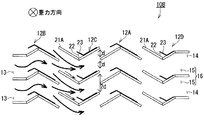
図8は、本発明の第5の実施形態に係る湿分分離ユニットの一例である第5の湿分分離ユニット10Eの横断面図である。   FIG. 8 is a cross-sectional view of a fifth moisture separation unit 10E which is an example of a moisture separation unit according to the fifth embodiment of the present invention.

第5の湿分分離ユニット10Eは、第1の湿分分離ユニット10Aに対して、第1列のガイド付ベーン12Bおよび第2列のノーマルベーン12Aと、第3列のノーマルベーン12Aおよび第4列のガイド付ベーン12Bとの代わりに、ガイド付ベーン12Gを備える点で相違する。   The fifth moisture separation unit 10E is different from the first moisture separation unit 10A in the first row of vanes with guides 12B, the second row of normal vanes 12A, the third row of normal vanes 12A, and the fourth row. A difference is that a vane 12G with guide is provided instead of the vane 12B with guide in the row.

ガイド付ベーン12Gは、横断面形状を略W字(またはM字)状に形成したベーン本体31と、蒸気から水を慣性分離して捕集するポケット32aを形成するポケット部材33とを備える。   The guide vane 12G includes a vane body 31 having a substantially W-shaped (or M-shaped) cross-sectional shape, and a pocket member 33 that forms a pocket 32a that inertially separates and collects water from steam.

ポケット32aは、ベーン本体31とポケット部材33とを壁面とする水捕集領域であり、その横断面形状(図3に示されるI−I線に沿う方向における断面の形状)は、三角形の一辺を開口部とする略三角形状に構成される。ポケット32aは、蒸気の流れ方向に対して上流側を向くように設けられる。   The pocket 32a is a water collection region having the vane body 31 and the pocket member 33 as wall surfaces, and its cross-sectional shape (cross-sectional shape in the direction along the line II shown in FIG. 3) is one side of a triangle. It is comprised in the substantially triangular shape which uses as an opening part. The pocket 32a is provided so as to face the upstream side with respect to the flow direction of the steam.

ポケット部材33は、ポケット部材23と同様に一箇所曲折した板状の部材であり、入口(開口部)が蒸気の流れ方向に対して上流側を向くようにベーン本体31に取り付けられる。すなわち、ポケット部材33は、ベーン本体31と相俟って上流側に開口したポケット32aを有するガイド付ベーン12Gを構成する。   The pocket member 33 is a plate-like member bent at one place similarly to the pocket member 23, and is attached to the vane body 31 so that the inlet (opening) faces the upstream side with respect to the flow direction of the steam. That is, the pocket member 33 constitutes the vane 12G with a guide having the pocket 32a opened on the upstream side together with the vane body 31.

例えば、図8に示されるガイド付ベーン12Gでは、横断面形状が略W字型に形成されたベーン本体31のWの直線部分に、三つのポケット部材33を取り付けることによって、三つのポケット32aが設けられる。このポケット32aは、ガイド付ベーン12Gを同じ列に配置した際に隣接する二つのガイド付ベーン12Gによって形成される流路15の区間において、蒸気が蛇行する際の外側となる位置に蒸気の流れ方向に対して上流側を開口させて設けられる。   For example, in the vane with guide 12G shown in FIG. 8, the three pockets 32a are formed by attaching the three pocket members 33 to the straight portion of W of the vane body 31 having a substantially W-shaped cross section. Provided. The pocket 32a has a flow of steam at a position on the outer side when the steam meanders in a section of the flow path 15 formed by two adjacent guide vanes 12G when the guided vanes 12G are arranged in the same row. It is provided with the upstream side opened with respect to the direction.

第5の湿分分離ユニット10Eでは、第1の湿分分離ユニット10Aと同様に、蒸気を導入口13から導出口14へ導く流路幅2dの流路15を複数有する流路群16が形成され、隣接する列のガイド付ベーン12Gが、蒸気の流動方向に対して垂直方向に流路幅2dの半分に相当する距離(半ピッチ)dずらして配置される。例えば、図8に示される第5の湿分分離ユニット10Eでは、第1列のガイド付ベーン12Gに対して、第2列のガイド付ベーン12Gは、下方向に半ピッチdずらして配置される。   In the fifth moisture separation unit 10E, as in the first moisture separation unit 10A, a channel group 16 having a plurality of channels 15 having a channel width 2d that leads the vapor from the inlet 13 to the outlet 14 is formed. The adjacent rows of guide vanes 12G are arranged at a distance (half pitch) d corresponding to half of the flow path width 2d in the direction perpendicular to the flow direction of the steam. For example, in the fifth moisture separation unit 10E shown in FIG. 8, the second row of guided vanes 12G is arranged so as to be shifted by a half pitch d downward from the first row of guided vanes 12G. .

このように構成された第5の湿分分離ユニット10Eでは、第1の湿分分離ユニット10Aと同様の現象が生じる。すなわち、第5の湿分分離ユニット10Eに流入した蒸気と水の二相流が、導入口13から第1列の区間に導かれた後、第1列の区間と第2列の区間との間で二つの隣接する流路15に分配される一方、第2列の区間では、第1列の区間に形成される二つの隣接する流路15からの二相流が合流する。   In the fifth moisture separation unit 10E configured as described above, a phenomenon similar to that of the first moisture separation unit 10A occurs. That is, after the two-phase flow of steam and water flowing into the fifth moisture separation unit 10E is led from the inlet 13 to the first row section, the first row section and the second row section In the second row section, the two-phase flows from the two adjacent flow paths 15 formed in the first row section merge.

また、ポケット32aの横断面の形状が略三角形状としたことによって、横断面の形状が略三角形状でない従来または第1〜第4の湿分分離ユニット10A〜10Dと比較して、ポケット32aによる流路15の縮流が緩和される。   Further, since the cross-sectional shape of the pocket 32a is substantially triangular, the pocket 32a has a cross-sectional shape that is not substantially triangular, as compared with the conventional or first to fourth moisture separation units 10A to 10D. The contracted flow in the flow path 15 is alleviated.

本実施の形態によれば、第5の湿分分離ユニット10Eへの流れが偏流しているために局所的にブレイクスルー流速より大きい流速で導入口13から各流路15へ流入した場合であっても、2列目以降の各区間で隣接する流路15に流れが分配されるため、下流に向かって流速が平均化される。従って、第5の湿分分離ユニット10Eおよび第5の湿分分離ユニット10Eを備える湿分分離装置70では流入分布に対して湿分除去のロバスト性を向上させることができる。   According to the present embodiment, since the flow to the fifth moisture separation unit 10E is unevenly distributed, the flow into the flow paths 15 from the inlet 13 is locally higher than the breakthrough flow rate. Even so, since the flow is distributed to the adjacent flow paths 15 in each section from the second row onward, the flow velocity is averaged toward the downstream. Therefore, the moisture separator 70 including the fifth moisture separation unit 10E and the fifth moisture separation unit 10E can improve moisture removal robustness with respect to the inflow distribution.

また、第5の湿分分離ユニット10Eおよび第5の湿分分離ユニット10Eを備える湿分分離装置70は、ポケット32aの横断面の形状が略三角形状であるため、横断面の形状が略三角形状でない従来または第1〜第4の湿分分離ユニット10A〜10Dと比較して、ポケット32aによる流路15の縮流を緩和することができる。   Further, in the moisture separator 70 provided with the fifth moisture separation unit 10E and the fifth moisture separation unit 10E, the shape of the cross section of the pocket 32a is substantially triangular, so the shape of the transverse section is substantially triangular. Compared with the conventional or first to fourth moisture separation units 10A to 10D that are not shaped, the contraction of the flow path 15 by the pocket 32a can be reduced.

[第6の実施形態]
本発明の第6の実施形態に係る湿分分離ユニットは、本発明の第5の実施形態に係る湿分分離ユニットに対して、流路15の構成、すなわち、ベーン12の形状および配置の観点で相違する。そこで、本実施形態の説明では、当該相違点を中心に説明し、同じ構成要素については同じ符号を付して説明を省略する。
[Sixth Embodiment]
The moisture separation unit according to the sixth embodiment of the present invention is different from the moisture separation unit according to the fifth embodiment of the present invention in terms of the configuration of the flow path 15, that is, the shape and arrangement of the vanes 12. Is different. Therefore, in the description of the present embodiment, the difference will be mainly described, and the same components are denoted by the same reference numerals and description thereof will be omitted.

本発明の第6の実施形態に係る湿分分離ユニットの一例である第6の湿分分離ユニット10Fは、例えば、図3に示される第1の湿分分離ユニット10Aと同様に構成される。すなわち、図3に示される符号10Aを10Fと読み替えれば、読み替え後の図3は第6の湿分分離ユニット10Fの構成を概略的に示した構成図となる。   A sixth moisture separation unit 10F, which is an example of a moisture separation unit according to the sixth embodiment of the present invention, is configured similarly to the first moisture separation unit 10A shown in FIG. 3, for example. That is, if the code | symbol 10A shown in FIG. 3 is read as 10F, FIG. 3 after reading will become a block diagram which showed schematically the structure of the 6th moisture separation unit 10F.

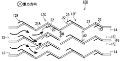
図9は、本発明の第6の実施形態に係る湿分分離ユニットの一例である第6の湿分分離ユニット10Fの横断面図である。   FIG. 9 is a cross-sectional view of a sixth moisture separation unit 10F that is an example of the moisture separation unit according to the sixth embodiment of the present invention.

第6の湿分分離ユニット10Fは、第5の湿分分離ユニット10Eに対して、流路15を構成する方向と、ガイド付ベーン12Gの代わりにガイド付ベーン12H,12Iを備える点で相違する。   The sixth moisture separation unit 10F is different from the fifth moisture separation unit 10E in that it includes the vanes 12H and 12I with guides instead of the direction of the flow path 15 and the vanes 12G with guides. .

ガイド付ベーン12H,12Iは、横断面形状を略W字(またはM字)状に形成したベーン本体31と、蒸気から水を慣性分離して捕集するポケット32bを形成するポケット部材33とを備える。   The vanes with guides 12H and 12I include a vane main body 31 having a substantially W-shaped (or M-shaped) cross-sectional shape, and a pocket member 33 that forms a pocket 32b that inertially separates and collects water from steam. Prepare.

ポケット32bは、ポケット32aと同様にベーン本体31とポケット部材33とを壁面とする横断面形状が略三角形状に構成された水捕集領域であり、ガイド付ベーン12Hを同じ列に配置した際に隣接する二つのガイド付ベーン12Hによって形成される流路15の区間において、蒸気が蛇行する際の外側となる位置に設けられる点で共通するが、ポケット32bが開口する方向は、蒸気の流れ方向に対して下流側(天井側)であり、蒸気の流れ方向に対して上流側を向くポケット32aの開口方向と異なる。   The pocket 32b is a water collecting region in which the cross-sectional shape with the vane body 31 and the pocket member 33 as the wall surface is configured in a substantially triangular shape, like the pocket 32a, and when the vanes 12H with guides are arranged in the same row In the section of the flow path 15 formed by the two guide vanes 12H adjacent to each other, it is common in that it is provided at a position outside the steam when meandering, but the direction in which the pocket 32b opens is the flow of steam. It is on the downstream side (ceiling side) with respect to the direction and is different from the opening direction of the pocket 32a facing the upstream side with respect to the flow direction of the steam.

このようなガイド付ベーン12H,12Iを立設して構成される第6の湿分分離ユニット10Fでは、蒸気を導入口13から導出口14へ導く流路幅2dの流路15を複数有する流路群16が形成され、隣接する列のガイド付ベーン12H,12Iが、蒸気の流動方向に対して垂直方向に流路幅2dの半分に相当する距離(半ピッチ)dずらして配置される。   In the sixth moisture separation unit 10F configured by standing these vanes 12H and 12I with guides, a flow having a plurality of channels 15 having a channel width 2d for guiding the steam from the inlet 13 to the outlet 14 is provided. A path group 16 is formed, and the guide vanes 12H and 12I in adjacent rows are arranged at a distance (half pitch) d corresponding to a half of the flow path width 2d in the direction perpendicular to the flow direction of the steam.

また、第6の湿分分離ユニット10Fは、流路15を構成する方向、すなわち、重力方向が、第1〜第5の湿分分離ユニット10A〜10Eの重力方向とは相違する。具体的には、第6の湿分分離ユニット10Fの重力方向は、図9に示されるように、紙面における左右方向となるが、第1〜第5の湿分分離ユニット10A〜10Eの重力方向は、図4〜図8に示されるように、紙面の表裏方向である。   In addition, the sixth moisture separation unit 10F has a direction in which the flow path 15 is formed, that is, a gravity direction, which is different from the gravity directions of the first to fifth moisture separation units 10A to 10E. Specifically, the gravity direction of the sixth moisture separation unit 10F is the left-right direction on the paper surface as shown in FIG. 9, but the gravity direction of the first to fifth moisture separation units 10A to 10E. Is the front and back direction of the paper as shown in FIGS.

また、ガイド付ベーン12Hは、ガイド付ベーン12Iに対してベーン本体31の下流(終端)側に返し部34をさらに設けて構成される。返し部34を設けることによって、返し部34の壁面に付着した水滴が重力落下する際に地面側に設けられ天井側を向いて開口するポケット32bで捕集することができ、水滴捕集(湿分分離)効果を高めることができる。   The guided vane 12H is configured by further providing a return portion 34 on the downstream (terminal) side of the vane body 31 with respect to the guided vane 12I. By providing the return portion 34, water droplets attached to the wall surface of the return portion 34 can be collected in the pocket 32b that is provided on the ground side and opens toward the ceiling side when the water drops are collected. Separation effect) can be enhanced.

例えば、図9に示される第6の湿分分離ユニット10Fでは、第1列にガイド付ベーン12Hが、第2列(最終列)にはガイド付ベーン12Iが設けられ、蒸気を地面側に設けられた導入口13から天井側に設けられた導出口14へ導くように構成される。また、ポケット32bは、蒸気の流れ方向に対して下流側(天井側)を開口させて設けられる。   For example, in the sixth moisture separation unit 10F shown in FIG. 9, a guided vane 12H is provided in the first row, a guided vane 12I is provided in the second row (final row), and steam is provided on the ground side. It is comprised so that it may guide | invade from the provided inlet 13 to the outlet 14 provided in the ceiling side. Further, the pocket 32b is provided with an opening on the downstream side (ceiling side) with respect to the steam flow direction.

このように構成された第6の湿分分離ユニット10Fでは、第5の湿分分離ユニット10Eと同様の現象が生じる。すなわち、第6の湿分分離ユニット10Fに流入した蒸気と水の二相流が、導入口13から第1列の区間に導かれた後、第1列の区間と第2列の区間との間で二つの隣接する流路15に分配される一方、第2列の区間では、第1列の区間に形成される二つの隣接する流路15からの二相流が合流する。また、従来または第1〜第4の湿分分離ユニット10A〜10Dと比較して、ポケット32bによる流路15の縮流が緩和される。   In the sixth moisture separation unit 10F configured as described above, the same phenomenon as that of the fifth moisture separation unit 10E occurs. That is, after the two-phase flow of steam and water flowing into the sixth moisture separation unit 10F is led from the inlet 13 to the first row section, the first row section and the second row section In the second row section, the two-phase flows from the two adjacent flow paths 15 formed in the first row section merge. Moreover, compared with the conventional or 1st-4th moisture separation unit 10A-10D, the contracted flow of the flow path 15 by the pocket 32b is relieve | moderated.

さらに、蒸気の流れ方向を重力が作用する方向と逆方向とし、ポケット32bを天井側に開口させて設けているため、下流側に向いて開口したポケット32bにはベーン本体31および返し部34の壁面に付着した水滴を重力落下により捕集することができる。   Further, since the flow direction of the steam is opposite to the direction in which the gravity acts and the pocket 32b is opened on the ceiling side, the pocket 32b opened toward the downstream side has the vane body 31 and the return portion 34 in the pocket 32b. Water droplets attached to the wall surface can be collected by gravity drop.

本実施の形態によれば、第5の湿分分離ユニット10Eおよび第5の湿分分離ユニット10Eを備える湿分分離装置70と同様の効果を奏することができる。すなわち、第6の湿分分離ユニット10Fおよび第6の湿分分離ユニット10Fを備える湿分分離装置70では流入分布に対して湿分除去のロバスト性を向上させることができ、かつ、従来または第1〜第4の湿分分離ユニット10A〜10Dと比較して、ポケット32bによる流路15の縮流を緩和することができる。   According to the present embodiment, it is possible to achieve the same effect as that of the moisture separator 70 provided with the fifth moisture separator unit 10E and the fifth moisture separator unit 10E. That is, in the moisture separator 70 including the sixth moisture separation unit 10F and the sixth moisture separation unit 10F, the robustness of moisture removal with respect to the inflow distribution can be improved, and the conventional or first Compared with the 1st-4th moisture separation units 10A-10D, the contraction of the flow path 15 by the pocket 32b can be eased.

なお、本実施の形態で説明した第6の湿分分離ユニット10Fは、上述したとおり重力方向が第1〜第5の湿分分離ユニット10A〜10Eとは異なり、ベーン12を水平方向に挟持する構成となる。従って、蒸気乾燥器70Aに適用する場合は、図1に示した構成と異なり、第6の湿分分離ユニット10Fの下方から被加熱蒸気S0が流入し、被加熱蒸気S1が第6の湿分分離ユニット10Fの上方へ抜けて高圧タービンに導かれ、第6の湿分分離ユニット10Fで捕集された水は側面から蒸気乾燥器70Aの外部へ排出される構成となる。   The sixth moisture separation unit 10F described in the present embodiment is different from the first to fifth moisture separation units 10A to 10E in the gravitational direction as described above, and sandwiches the vane 12 in the horizontal direction. It becomes composition. Therefore, when applied to the steam dryer 70A, unlike the configuration shown in FIG. 1, the heated steam S0 flows from below the sixth moisture separation unit 10F, and the heated steam S1 becomes the sixth moisture. The water passing through the separation unit 10F and guided to the high-pressure turbine and collected by the sixth moisture separation unit 10F is discharged from the side to the outside of the steam dryer 70A.

[第7の実施形態]
本発明の第7の実施形態に係る湿分分離ユニットは、本発明の第6の実施形態に係る湿分分離ユニットに対して、流路15の方向、すなわち、ベーン12の配置方向の観点で相違する。そこで、本実施形態の説明では、当該相違点を中心に説明し、同じ構成要素については同じ符号を付して説明を省略する。
[Seventh Embodiment]
The moisture separation unit according to the seventh embodiment of the present invention is different from the moisture separation unit according to the sixth embodiment of the present invention in terms of the direction of the flow path 15, that is, the arrangement direction of the vanes 12. Is different. Therefore, in the description of the present embodiment, the difference will be mainly described, and the same components are denoted by the same reference numerals and description thereof will be omitted.

本発明の第7の実施形態に係る湿分分離ユニットの一例である第7の湿分分離ユニット10Gは、例えば、図3に示される第1の湿分分離ユニット10Aと同様に構成される。すなわち、図3に示される符号10Aを10Gと読み替えれば、読み替え後の図3は第7の湿分分離ユニット10Gの構成を概略的に示した構成図となる。   A seventh moisture separation unit 10G, which is an example of a moisture separation unit according to the seventh embodiment of the present invention, is configured similarly to the first moisture separation unit 10A shown in FIG. 3, for example. That is, if the code | symbol 10A shown in FIG. 3 is read as 10G, FIG. 3 after reading will become a block diagram which showed schematically the structure of the 7th moisture separation unit 10G.

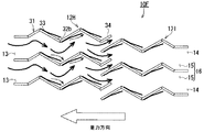
図10は、本発明の第7の実施形態に係る湿分分離ユニットの一例である第7の湿分分離ユニット10Gの横断面図である。   FIG. 10 is a cross-sectional view of a seventh moisture separation unit 10G which is an example of a moisture separation unit according to the seventh embodiment of the present invention.

第7の湿分分離ユニット10Gは、第6の湿分分離ユニット10Fに対して、流路15を構成する方向と、ガイド付ベーン12H,12Iの代わりに、ガイド付ベーン12J,12Kを備える点で相違する。すなわち、第7の湿分分離ユニット10Gでは、蒸気を導入口13から導出口14へ導く流路幅2dの流路15を複数有する流路群16が形成され、隣接する列のガイド付ベーン12J,12Kが、蒸気の流動方向に対して垂直方向に流路幅2dの半分に相当する距離(半ピッチ)dずらして配置される。   The seventh moisture separation unit 10G includes guide vanes 12J and 12K instead of the guide vanes 12H and 12I with respect to the sixth moisture separation unit 10F. Is different. That is, in the seventh moisture separation unit 10G, a flow path group 16 having a plurality of flow paths 15 having a flow path width 2d that guides the vapor from the inlet 13 to the outlet 14 is formed, and the guide vanes 12J in adjacent rows are formed. , 12K are arranged at a distance (half pitch) d corresponding to half of the flow path width 2d in the direction perpendicular to the flow direction of the steam.

また、第7の湿分分離ユニット10Gは、流路15を構成する方向、すなわち、重力方向が、第1〜第5の湿分分離ユニット10A〜10Eや第6の湿分分離ユニット10Fの重力方向とは相違する。具体的には、第7の湿分分離ユニット10Gの重力方向は、図10に示されるように、紙面における上下方向となる。   In addition, the seventh moisture separation unit 10G has the direction of the flow path 15, that is, the direction of gravity is the gravity of the first to fifth moisture separation units 10A to 10E and the sixth moisture separation unit 10F. It is different from the direction. Specifically, the gravitational direction of the seventh moisture separation unit 10G is the vertical direction on the paper surface as shown in FIG.

ガイド付ベーン12Jは、ベーン本体31のWの直線部分にポケット部材33を取り付けるとともに、ベーン本体31の下流(終端)側に返し部34をさらに設けて構成される点でガイド付ベーン12Hと共通するが、蒸気の流れ方向に対して上流側に開口させたポケット32aと、蒸気の流れ方向に対して下流側に開口させたポケット32bとを有するようにポケット部材33を取り付ける点で相違する。   The vane 12J with guide is common to the vane 12H with guide in that the pocket member 33 is attached to the straight portion of W of the vane body 31 and a return portion 34 is further provided on the downstream (terminal) side of the vane body 31. However, it is different in that the pocket member 33 is attached so as to have a pocket 32a opened on the upstream side in the steam flow direction and a pocket 32b opened on the downstream side in the steam flow direction.

また、ガイド付ベーン12Kは、ベーン本体31のWの直線部分に、蒸気の流れ方向に対して上流側に開口させたポケット32aと、蒸気の流れ方向に対して下流側に開口させたポケット32bとを有するようにポケット部材33を取り付けて構成される。   Further, the vane 12K with a guide has a pocket 32a opened on the upstream side with respect to the steam flow direction and a pocket 32b opened on the downstream side with respect to the steam flow direction in the straight portion W of the vane body 31. The pocket member 33 is attached so as to have.

このようなガイド付ベーン12H,12Iを立設して構成される第7の湿分分離ユニット10Gでは、蒸気を導入口13から導出口14へ導く流路幅2dの流路15を複数有する流路群16が形成され、隣接する列のガイド付ベーン12J,12Kが、蒸気の流動方向に対して垂直方向に流路幅2dの半分に相当する距離(半ピッチ)dずらして配置される。   In the seventh moisture separation unit 10G configured by standing such vanes with guides 12H and 12I, a flow having a plurality of channels 15 having a channel width 2d for guiding steam from the inlet 13 to the outlet 14 is provided. A path group 16 is formed, and the guide vanes 12J and 12K in adjacent rows are arranged at a distance (half pitch) d corresponding to half of the flow path width 2d in the direction perpendicular to the flow direction of the steam.

また、第7の湿分分離ユニット10Gは、流路15を構成する方向、すなわち、重力方向が、第1〜第5の湿分分離ユニット10A〜10Eや第6の湿分分離ユニット10Fの重力方向とは相違する。具体的には、第7の湿分分離ユニット10Gは、図10に示されるように、紙面における上下方向となる。   In addition, the seventh moisture separation unit 10G has the direction of the flow path 15, that is, the direction of gravity is the gravity of the first to fifth moisture separation units 10A to 10E and the sixth moisture separation unit 10F. It is different from the direction. Specifically, the seventh moisture separation unit 10G is in the vertical direction on the paper surface as shown in FIG.

さらに、第7の湿分分離ユニット10Gでは、蒸気の流動方向に対して上流側に開口したポケット32aが天井側(図10に示される上側)を向くことになるので、壁面に付着した液膜をポケット32aで直接捕集することができるとともに、蒸気の流動方向に対して下流側に開口したポケット32bが地面側(図10に示される下側)になるので、壁面に付着し重力で溜まった液膜をポケット32bで捕集することができる。   Further, in the seventh moisture separation unit 10G, the pocket 32a opened upstream with respect to the flow direction of the steam faces the ceiling side (the upper side shown in FIG. 10), so that the liquid film adhered to the wall surface Can be directly collected by the pocket 32a, and the pocket 32b opened downstream with respect to the flow direction of the steam is on the ground side (the lower side shown in FIG. 10). The liquid film can be collected in the pocket 32b.

本実施の形態によれば、第5の湿分分離ユニット10Eおよび第5の湿分分離ユニット10Eを備える湿分分離装置70と同様の効果を奏することができる。すなわち、第7の湿分分離ユニット10Gおよび第7の湿分分離ユニット10Gを備える湿分分離装置70では、流入分布に対して湿分除去のロバスト性を向上させることができ、かつ、従来または第1〜第4の湿分分離ユニット10A〜10Dと比較して、ポケット32a,32bによる流路15の縮流を緩和することができる。   According to the present embodiment, it is possible to achieve the same effect as that of the moisture separator 70 provided with the fifth moisture separator unit 10E and the fifth moisture separator unit 10E. That is, in the moisture separation device 70 including the seventh moisture separation unit 10G and the seventh moisture separation unit 10G, the robustness of moisture removal with respect to the inflow distribution can be improved, and the conventional or Compared with the first to fourth moisture separation units 10A to 10D, the contraction of the flow path 15 by the pockets 32a and 32b can be reduced.

以上、本発明の実施形態に係る湿分分離ユニットおよび湿分分離ユニットを備える湿分分離装置によれば、従来の湿分分離ユニットおよび当該湿分分離ユニットを備える湿分分離ユニットよりも流入分布に対して湿分除去のロバスト性を向上させることができる。   As described above, according to the moisture separation device including the moisture separation unit and the moisture separation unit according to the embodiment of the present invention, the inflow distribution is higher than the conventional moisture separation unit and the moisture separation unit including the moisture separation unit. On the other hand, the robustness of moisture removal can be improved.

以上、本発明の幾つかの実施形態を説明したが、これらの実施形態は、例として提示したものであり、発明の範囲を限定することは意図していない。これら新規な実施形態は、その他の様々な形態で実施されることが可能であり、発明の要旨を逸脱しない範囲で、種々の省略、置き換え、変更を行うことができる。例えば、図4に示される第1の湿分分離ユニット10Aでは、ガイド24をノーマルベーン12Aの一端に設けたガイド付ベーン12Bを備える場合を説明しているが、第1の湿分分離ユニット10Aでは必ずしもガイド24とノーマルベーン12Aとが一体的に構成されている必要はなく、ガイド24とノーマルベーン12Aとが一体的に構成されるガイド付ベーン12Bの代わりに、ガイド24とノーマルベーン12Aとを個別に配置した構成を採用することもできる。これら実施形態やその変形は、発明の範囲や要旨に含まれるとともに、特許請求の範囲に記載された発明とその均等の範囲に含まれる。   As mentioned above, although several embodiment of this invention was described, these embodiment is shown as an example and is not intending limiting the range of invention. These novel embodiments can be implemented in various other forms, and various omissions, replacements, and changes can be made without departing from the scope of the invention. For example, in the first moisture separation unit 10A shown in FIG. 4, a case is described in which the guide vane 12B is provided with the guide 24 provided at one end of the normal vane 12A. Then, the guide 24 and the normal vane 12A do not necessarily have to be integrally formed. Instead of the guide vane 12B in which the guide 24 and the normal vane 12A are integrally formed, the guide 24 and the normal vane 12A are It is also possible to adopt a configuration in which these are individually arranged. These embodiments and modifications thereof are included in the scope and gist of the invention, and are included in the invention described in the claims and the equivalents thereof.

10(10A〜10G) 湿分分離ユニット
11 挟持板
12(12A〜12K) ベーン
13 導入口
14 導出口
15 流路
16 流路群
21(21A,21B) ベーン本体
22 ポケット
23 ポケット部材
24 ガイド
31 ベーン本体
32a,32b ポケット
33 ポケット部材
34 返し部
70 湿分分離装置
70A 蒸気乾燥器
70B 湿分分離加熱器
71 ドレン樋
72 ドレン管
73 ケーシング
81 本体容器
82a 第一段加熱器
82b 第二段加熱器
83 底板
84 天井板
85 ドレン流路
87 被加熱蒸気入口
88 被加熱蒸気出口
91 流路仕切板
92a,92b 流路仕切板
95a,95b 伝熱管
10 (10A to 10G) Moisture separation unit 11 Holding plate 12 (12A to 12K) Vane 13 Inlet 14 Outlet 15 Channel 16 Channel group 21 (21A, 21B) Vane main body 22 Pocket 23 Pocket member 24 Guide 31 Vane Main body 32a, 32b Pocket 33 Pocket member 34 Return portion 70 Moisture separator 70A Steam dryer 70B Moisture separator heater 71 Drain trough 72 Drain pipe 73 Casing 81 Main body container 82a First stage heater 82b Second stage heater 83 Bottom plate 84 Ceiling plate 85 Drain flow path 87 Heated steam inlet 88 Heated steam outlet 91 Channel partition plates 92a and 92b Channel partition plates 95a and 95b Heat transfer tubes

Claims (11)

曲折した複数の流路を有し、当該流路に導入する蒸気に含まれる湿分を分離する湿分分離ユニットにおいて、
前記流路の導入口から導出口まで全長を複数の区間に分割し、一の流路の導入口から導入された蒸気の少なくとも一部を他の流路の導出口から導出するように構成されたことを特徴とする湿分分離ユニット。
In a moisture separation unit that has a plurality of bent flow paths and separates moisture contained in steam introduced into the flow paths,
The entire length from the inlet to the outlet of the flow path is divided into a plurality of sections, and at least a part of the steam introduced from the inlet of one flow path is led out from the outlet of the other flow path. Moisture separation unit characterized by that.
前記流路の複数に分割された区間を構成し、前記蒸気から分離した湿分を捕集するポケットを設けたベーンと、
前記導入口と前記導出口とを結ぶ方向に対して垂直方向に立設させた前記ベーンを立設する両端側から挟んで保持する二枚の板状体と、を備え、
前記ベーンは、前記導入口と前記導出口とを結ぶ第1の方向および前記第1の方向に対して垂直方向となる第2の方向の両方向に対して行列状に配置され、前記導入口から数えて同列となる区間では前記第2の方向と平行方向に所定距離を隔てて配置され、かつ、隣接する区間の何れかでは前記第2の方向と平行方向に前記流路の幅よりも短い距離をずらして配置されることを特徴とする請求項1記載の湿分分離ユニット。
A vane having a section divided into a plurality of the flow paths and provided with a pocket for collecting moisture separated from the steam;
Two plate-like bodies that are sandwiched and held from both ends of the vane that are erected in a direction perpendicular to the direction connecting the introduction port and the outlet port, and
The vanes are arranged in a matrix in both a first direction connecting the inlet and the outlet and a second direction perpendicular to the first direction, from the inlet. The sections that are counted in the same row are arranged at a predetermined distance in a direction parallel to the second direction, and any one of the adjacent sections is shorter than the width of the flow path in the direction parallel to the second direction. The moisture separation unit according to claim 1, wherein the moisture separation unit is arranged at a distance.
前記ベーンは、立設する方向に対して垂直方向の横断面の形状が、直線を1回以上曲折させた形状であることを特徴とする請求項2記載の湿分分離ユニット。 The moisture separation unit according to claim 2, wherein the vane has a shape of a cross section perpendicular to a direction in which the vane is erected, wherein the straight line is bent one or more times. 前記ベーンは、立設する方向に対して垂直方向における横断面の形状がV字型に構成されており、前記第1の方向に隣接する区間に配置されるベーンの前記V字型の突出方向は、相互に逆方向となるように配置されることを特徴とする請求項2又は3記載の湿分分離ユニット。 The vane has a V-shaped cross-sectional shape in a direction perpendicular to the standing direction, and the V-shaped protruding direction of the vane arranged in the section adjacent to the first direction. 4. The moisture separation unit according to claim 2, wherein the moisture separation units are arranged in opposite directions to each other. 前記ベーンの始端位置は、前記蒸気が流動する方向に対して上流側に位置する隣の区間のベーンの終端位置よりも、前記蒸気が流動する方向に対して上流側となる位置に配置されることを特徴とする請求項4記載の湿分分離ユニット。 The start end position of the vane is disposed at a position upstream of the vane end position of the adjacent section located upstream with respect to the direction in which the steam flows. The moisture separation unit according to claim 4. 前記ベーンが立設する方向に対して垂直方向における前記ポケットの横断面の形状は、一辺を開口部とした三角形状であることを特徴とする請求項2〜5の何れか1項に記載の湿分分離ユニット。 The shape of the cross section of the pocket in a direction perpendicular to the direction in which the vane stands is a triangular shape having one side as an opening portion, according to any one of claims 2 to 5. Moisture separation unit. 前記ベーンが立設する方向に対して垂直方向における前記ポケットの横断面の形状は、一辺を開口部とした三角形状であり、前記ポケットの開口方向は、前記蒸気が流動する方向に対して上流側を向いて構成されことを特徴とする請求項2〜5の何れか1項に記載の湿分分離ユニット。 The shape of the cross section of the pocket in a direction perpendicular to the direction in which the vane stands is a triangular shape with an opening on one side, and the opening direction of the pocket is upstream of the direction in which the steam flows. The moisture separation unit according to any one of claims 2 to 5, wherein the moisture separation unit is directed to the side. 前記ベーンは、立設する方向に対して垂直方向における横断面の形状がW字型に構成される一方、
前記導入口は地面側に、前記導出口は天井側に設けられ、
前記ベーンが立設する方向に対して垂直方向における前記ポケットの横断面の形状は、一辺を開口部とした三角形状であり、前記ポケットの開口方向は、前記蒸気の流動する方向に対して下流側を向いて構成されことを特徴とする請求項2又は3記載の湿分分離ユニット。
The vane has a W-shaped cross section in a direction perpendicular to the direction in which the vane stands.
The inlet is provided on the ground side, and the outlet is provided on the ceiling side,
The shape of the cross section of the pocket in a direction perpendicular to the direction in which the vane stands is a triangular shape with an opening on one side, and the opening direction of the pocket is downstream of the direction in which the steam flows. 4. A moisture separation unit according to claim 2 or 3, wherein the moisture separation unit is directed to the side.
前記ベーンは、立設する方向に対して垂直方向における横断面の形状がW字型に構成される一方、前記ベーンの曲折点が重力方向となるように配置され、
前記ベーンが立設する方向に対して垂直方向における前記ポケットの横断面の形状は、一辺を開口部とした三角形状であり、前記ポケットは、その開口方向が前記蒸気の流動する方向に対して上流側を向いたものと下流側を向いたものとで構成されことを特徴とする請求項2又は3記載の湿分分離ユニット。
The vane is arranged so that the shape of the cross section in the direction perpendicular to the direction of standing is W-shaped, while the bending point of the vane is in the direction of gravity,
The shape of the cross section of the pocket in a direction perpendicular to the direction in which the vane stands is a triangular shape with an opening on one side, and the pocket has an opening direction with respect to the direction in which the steam flows. The moisture separation unit according to claim 2 or 3, wherein the moisture separation unit is composed of an upstream side and a downstream side.
前記ベーンは、前記蒸気が流動する方向に対して下流側に位置する端部に板状の返し部を設けたことを特徴とする請求項8又は9記載の湿分分離ユニット。 The moisture separation unit according to claim 8 or 9, wherein the vane is provided with a plate-like return portion at an end located downstream of the direction in which the steam flows. 請求項1乃至10の何れか1項に記載の湿分分離ユニットを備えることを特徴とする湿分分離装置。 A moisture separation apparatus comprising the moisture separation unit according to claim 1.
JP2011004230A 2011-01-12 2011-01-12 Moisture separation unit and moisture separation device equipped with the moisture separation unit Active JP5535096B2 (en)

Priority Applications (1)

Application Number Priority Date Filing Date Title
JP2011004230A JP5535096B2 (en) 2011-01-12 2011-01-12 Moisture separation unit and moisture separation device equipped with the moisture separation unit

Applications Claiming Priority (1)

Application Number Priority Date Filing Date Title
JP2011004230A JP5535096B2 (en) 2011-01-12 2011-01-12 Moisture separation unit and moisture separation device equipped with the moisture separation unit

Publications (2)

Publication Number Publication Date
JP2012143710A true JP2012143710A (en) 2012-08-02
JP5535096B2 JP5535096B2 (en) 2014-07-02

Family

ID=46787848

Family Applications (1)

Application Number Title Priority Date Filing Date
JP2011004230A Active JP5535096B2 (en) 2011-01-12 2011-01-12 Moisture separation unit and moisture separation device equipped with the moisture separation unit

Country Status (1)

Country Link
JP (1) JP5535096B2 (en)

Cited By (4)

* Cited by examiner, † Cited by third party
Publication number Priority date Publication date Assignee Title
CN106932809A (en) * 2015-12-30 2017-07-07 核工业西南物理研究院 A kind of hot target structure of active water cold of many plate angle combining structures of W fonts
US20210172596A1 (en) * 2019-12-10 2021-06-10 Doosan Heavy Industries & Construction Co., Ltd. Chevron vane and moisture separator including same
KR20210132972A (en) * 2020-04-28 2021-11-05 한양대학교 산학협력단 Apparatus for droplet removal
US12000586B2 (en) 2019-12-10 2024-06-04 Doosan Enerbility Co., Ltd. Chevron vane and moisture separator including same

Citations (7)

* Cited by examiner, † Cited by third party
Publication number Priority date Publication date Assignee Title
JPS4878471U (en) * 1971-12-25 1973-09-27
JPS4989258A (en) * 1972-12-29 1974-08-26
JPS547470U (en) * 1978-06-02 1979-01-18
JPS54122482U (en) * 1978-02-17 1979-08-27
JPH0347017U (en) * 1989-09-13 1991-04-30
JP2002126429A (en) * 2000-10-20 2002-05-08 Mitsubishi Heavy Ind Ltd Moisture separator
JP2005034744A (en) * 2003-07-15 2005-02-10 Taikisha Ltd Droplet collection device and coating booth using the same

Patent Citations (7)

* Cited by examiner, † Cited by third party
Publication number Priority date Publication date Assignee Title
JPS4878471U (en) * 1971-12-25 1973-09-27
JPS4989258A (en) * 1972-12-29 1974-08-26
JPS54122482U (en) * 1978-02-17 1979-08-27
JPS547470U (en) * 1978-06-02 1979-01-18
JPH0347017U (en) * 1989-09-13 1991-04-30
JP2002126429A (en) * 2000-10-20 2002-05-08 Mitsubishi Heavy Ind Ltd Moisture separator
JP2005034744A (en) * 2003-07-15 2005-02-10 Taikisha Ltd Droplet collection device and coating booth using the same

Cited By (7)

* Cited by examiner, † Cited by third party
Publication number Priority date Publication date Assignee Title
CN106932809A (en) * 2015-12-30 2017-07-07 核工业西南物理研究院 A kind of hot target structure of active water cold of many plate angle combining structures of W fonts
US20210172596A1 (en) * 2019-12-10 2021-06-10 Doosan Heavy Industries & Construction Co., Ltd. Chevron vane and moisture separator including same
KR20210073271A (en) * 2019-12-10 2021-06-18 두산중공업 주식회사 Chevron vane and moisture separator comprising the same
KR102340656B1 (en) * 2019-12-10 2021-12-17 두산중공업 주식회사 Chevron vane and moisture separator comprising the same
US12000586B2 (en) 2019-12-10 2024-06-04 Doosan Enerbility Co., Ltd. Chevron vane and moisture separator including same
KR20210132972A (en) * 2020-04-28 2021-11-05 한양대학교 산학협력단 Apparatus for droplet removal
KR102389524B1 (en) 2020-04-28 2022-04-22 한양대학교 산학협력단 Apparatus for droplet removal

Also Published As

Publication number Publication date
JP5535096B2 (en) 2014-07-02

Similar Documents

Publication Publication Date Title
JP5535096B2 (en) Moisture separation unit and moisture separation device equipped with the moisture separation unit
US9905319B2 (en) Plate heat exchanger for homogeneous fluid flows between ducts
NO342760B1 (en) Heat exchanger core
EP3050063B1 (en) Steam generator and method of securing tubes within a steam generator against vibration
ES2479465T3 (en) Power distribution device for a separation column
KR101255926B1 (en) Moisture separation heater
EP2682701B1 (en) Multistage pressure condenser and steam turbine plant equipped with same
EP2246616B1 (en) Steam generator
WO2007088858A1 (en) Moisture separation and heating device
JP2005127650A (en) Plate fin type regenerative heat exchanger and gas turbine power generation system
EP3109545B1 (en) Moisture separator/heater
JP7144265B2 (en) moisture separators and steam turbine plants
JP2002122303A (en) Moisture separating heater
US8673039B2 (en) Enhanced vane bundle design
JP2015124925A (en) Moisture separation unit, droplet size coarsening device, and steam dryer
CN107923611B (en) Hygroscopic water separator and steam turbine plant
JP2021076315A (en) Multi-tube condenser
JP6789855B2 (en) Turbine system for condensers and power plants
JP2020056531A5 (en)
JP6081110B2 (en) Combined condenser
JP6685809B2 (en) Condenser
US20010025703A1 (en) Condenser
JPH05312994A (en) Humidity separation heating device
JP5938243B2 (en) Tower condenser
JPS6284207A (en) Moisture separating reheater

Legal Events

Date Code Title Description
A621 Written request for application examination

Free format text: JAPANESE INTERMEDIATE CODE: A621

Effective date: 20130711

A977 Report on retrieval

Free format text: JAPANESE INTERMEDIATE CODE: A971007

Effective date: 20131111

A131 Notification of reasons for refusal

Free format text: JAPANESE INTERMEDIATE CODE: A131

Effective date: 20131119

A521 Written amendment

Free format text: JAPANESE INTERMEDIATE CODE: A523

Effective date: 20140117

TRDD Decision of grant or rejection written
A01 Written decision to grant a patent or to grant a registration (utility model)

Free format text: JAPANESE INTERMEDIATE CODE: A01

Effective date: 20140325

A61 First payment of annual fees (during grant procedure)

Free format text: JAPANESE INTERMEDIATE CODE: A61

Effective date: 20140422

R151 Written notification of patent or utility model registration

Ref document number: 5535096

Country of ref document: JP

Free format text: JAPANESE INTERMEDIATE CODE: R151