JP2012143089A - Motor - Google Patents
Motor Download PDFInfo
- Publication number
- JP2012143089A JP2012143089A JP2011000178A JP2011000178A JP2012143089A JP 2012143089 A JP2012143089 A JP 2012143089A JP 2011000178 A JP2011000178 A JP 2011000178A JP 2011000178 A JP2011000178 A JP 2011000178A JP 2012143089 A JP2012143089 A JP 2012143089A
- Authority
- JP
- Japan
- Prior art keywords
- conductor
- phase
- conductor portion
- winding
- slot
- Prior art date
- Legal status (The legal status is an assumption and is not a legal conclusion. Google has not performed a legal analysis and makes no representation as to the accuracy of the status listed.)
- Pending
Links
Images


Landscapes
- Windings For Motors And Generators (AREA)
- Insulation, Fastening Of Motor, Generator Windings (AREA)
- Motor Or Generator Frames (AREA)
Abstract
Description
本発明は、モータに関するものである。 The present invention relates to a motor.
近年、モータについて、コギングトルクの低減及びモータの体格の小体格化が望まれている。特に、自動車に実装される各種のモータ、例えばパワーステアリング装置に使用されるEPSモータにおいては、さらなるコギングトルクの低減及びモータの体格の小体格化が要求されている。 In recent years, reduction of cogging torque and reduction in the physique of motors have been desired for motors. In particular, various motors mounted on automobiles, such as EPS motors used in power steering devices, are required to further reduce cogging torque and reduce the size of the motor.
そこで、コギングトルクの低減及びモータの体格の小体格化を図る手段として、ステータのSC(セグメントコンダクタ)巻線化が注目され、ステータにSC巻線を施したブラシレスモータが種々提案されている(例えば、特許文献1)。 Therefore, as a means for reducing cogging torque and reducing the physique of the motor, attention has been paid to the SC (segment conductor) winding of the stator, and various brushless motors in which the stator is provided with the SC winding have been proposed ( For example, Patent Document 1).
SC巻線とは、U字状のセグメントと呼ばれる分割導体をステータコアの各スロットに、軸線方向から挿入し、反対側を後工程において溶接等で接続して周方向に連続巻線を形成する巻線をいう。このSC巻線は、スロット数を多くすることができコギングトルクを低減させることができるとともに、スロット内の巻線の占有率が向上し、出力当たりのモータの体格を小体格化することができる。 The SC winding is a winding in which a split conductor called a U-shaped segment is inserted into each slot of the stator core from the axial direction, and the opposite side is connected by welding or the like in a subsequent process to form a continuous winding in the circumferential direction. Say a line. This SC winding can increase the number of slots and reduce cogging torque, improve the occupancy of the winding in the slot, and reduce the physique of the motor per output. .
また、一方で、SC巻線のステータは、U字状のセグメントの先端部間を溶接等で接続することから、隣接する溶接部間がショートしないように、溶接部間を径方向に若干離間させていることから、その分だけ径方向が大きくなり、体格上若干不利な面もある。 On the other hand, since the stator of the SC winding connects the tip portions of the U-shaped segments by welding or the like, the welded portions are slightly separated in the radial direction so as not to short-circuit between adjacent welded portions. As a result, the radial direction is increased accordingly, and there is a slight disadvantage in the physique.
また、パワーステアリング装置に使用されるEPSモータにおいては、システム全体として小型化を図るために、筒状フレームの径方向外周面に制御回路ユニットを合体したものが提案されている(例えば、特許文献2)。 In addition, an EPS motor used in a power steering apparatus has been proposed in which a control circuit unit is combined with a radially outer peripheral surface of a cylindrical frame in order to reduce the size of the entire system (for example, Patent Documents). 2).
ところで、文献2に示す制御回路ユニットを合体したモータのステータについて、SC巻線に単に転用しても、制御回路ユニットがステータを内蔵する筒状フレームの径方向外周面に位置するため、制御回路ユニットが取着されている分、径方向の体格が大きいままで小型化を図ることはできなかった。
By the way, even if the stator of the motor combined with the control circuit unit shown in
また、制御回路ユニットからの電力を受電する場合、制御回路ユニットから引出線が筒状フレーム内に挿入され、引出線の一端が筒状フレーム内でSC巻線の電力受電端子と接続を行うとともに、引出線の他端が制御回路ユニット内に設けた回路基板に設けた出力端子との接続を制御回路ユニット内で行う必要があり、軸方向及び径方向に大であるままとなる。 When receiving power from the control circuit unit, a lead wire is inserted from the control circuit unit into the cylindrical frame, and one end of the lead wire is connected to the power receiving terminal of the SC winding in the cylindrical frame. The other end of the lead wire needs to be connected in the control circuit unit to the output terminal provided in the circuit board provided in the control circuit unit, and remains large in the axial direction and the radial direction.
本発明は上記問題点を解消するためになされたものであって、その目的は、コギングトルクを低減できるSC巻線のモータの体格を小体格にできとともに、制御回路を有するモータ全体の体格を小体格にできるモータを提供することにある。 The present invention has been made in order to solve the above-mentioned problems. The object of the present invention is to reduce the physique of the SC winding motor that can reduce the cogging torque, and to reduce the physique of the entire motor having the control circuit. The object is to provide a motor that can be made small.
請求項1に記載の発明は、筒状ケースのフロント側開口部にフロントカバーが取着され、筒状ケースのリア側開口部にリアカバーが取着されなるモータケースと、前記モータケース内に配設され、回転軸の中心軸線に向かって延出形成されたてティースが径方向に等間隔に複数個配置され、ティースとティース間に形成される軸線方向に延びる各スロットに、U字状のセグメントが一方向から挿入され、各スロットから突出した先端間を周方向に繋げてなるSC巻線にて形成されたステータとを備えたモータであって、前記ステータを、周方向に繋げたU字状のセグメントの先端間の溶接部がフロントカバーに、SC巻線の電力受電端子がリアカバーにそれぞれ対峙するように、モータケースに配設し、前記SC巻線の電力受電端子をそのまま引出線としあるいは引出線を接続し、その引出線を軸方向に延出させてリアカバーに形成した貫通孔から突出させて前記リアカバーに隣接する制御回路の端子と接続するようにした。 According to the first aspect of the present invention, there is provided a motor case in which a front cover is attached to the front side opening of the cylindrical case and a rear cover is attached to the rear side opening of the cylindrical case, and the motor case is disposed in the motor case. A plurality of teeth, which are formed to extend toward the central axis of the rotating shaft, are arranged at equal intervals in the radial direction, and each slot extending between the teeth and extending in the axial direction has a U-shape. A motor comprising a stator formed by SC winding in which segments are inserted from one direction and tip ends protruding from the slots are connected in the circumferential direction, and the stator is connected in the circumferential direction. The welded portion between the tips of the letter-shaped segments is placed in the motor case so that the welded portion between the front end and the SC coil power receiving terminal faces the rear cover. A lead line or to connect the lead wire and be connected with it by extending its lead wire in the axial direction is protruded from the through hole formed in the rear cover terminal of the control circuit adjacent to the rear cover.
請求項1に記載の発明によれば、ステータのSC巻線の電力受電端子を、フロントカバー側に設けたU字状のセグメントの先端間の溶接部と反対側のリアカバー側に設けたので、電力受電端子は密集する溶接部を避けて形成することができ、モータの体格が小体格となる。また、U字状のセグメントの先端間の溶接部ではなく、寸法形成されたU字状のセグメントの基端部をリアカバー側としたので、SC巻線を形成する各U字状のセグメントの基端部とリアカバーと間のクリアランスを短くでき、モータの体格が小体格となる。 According to the first aspect of the present invention, the power receiving terminal of the SC winding of the stator is provided on the rear cover side opposite to the welded portion between the tips of the U-shaped segments provided on the front cover side. The power receiving terminal can be formed avoiding densely welded portions, and the physique of the motor becomes a small physique. Further, since the base end portion of the U-shaped segment having a dimension formed is not the welded portion between the distal ends of the U-shaped segment, and the base portion of each U-shaped segment forming the SC winding is used. The clearance between the end portion and the rear cover can be shortened, and the physique of the motor becomes a small physique.
また、電力受電端子に接続された引出線は、寸法形成されたU字状のセグメントの基端部からそのまま軸方向に引き出してくるので、制御回路端子との接続が容易となる。リアカバー側に設けた電力受電端子は、軸線方向に引き出されリアカバーに形成した貫通孔を貫通してリアカバーに隣接する制御回路の端子されるようにしたので、制御回路の部品をその内径側に置くことが可能になり、制御回路を有するモータの体格が全体として小体格となる。さらに、溶接部をフロントカバー側、すなわち、制御回路と反対側にしたことで、溶接時の残渣が回路側接点に付着することも抑制できる。 In addition, since the lead wire connected to the power receiving terminal is pulled out in the axial direction as it is from the base end portion of the U-shaped segment that is dimensionally formed, the connection with the control circuit terminal becomes easy. The power receiving terminal provided on the rear cover side is pulled out in the axial direction and penetrates the through hole formed in the rear cover so as to be a terminal of the control circuit adjacent to the rear cover. Therefore, the physique of the motor having the control circuit becomes a small physique as a whole. Furthermore, since the welded portion is on the front cover side, that is, on the side opposite to the control circuit, it is possible to suppress the residue from welding from adhering to the circuit side contact.
請求項2に記載の発明は、請求項1に記載のモータにおいて、前記電力受電端子は、スロットS内の径方向において外側の位置にそれぞれ配置され、その電力受電端子に接続された前記引出線が軸線方向にリアカバーに形成した貫通孔を介して前記制御回路の端子と接続した。 According to a second aspect of the present invention, in the motor according to the first aspect, the power receiving terminal is disposed at a position outside in the radial direction in the slot S, and is connected to the power receiving terminal. Was connected to the terminal of the control circuit through a through hole formed in the rear cover in the axial direction.
請求項2に記載の発明によれば、リアカバー側に設けた電力受電端子は、スロットS内の径方向において外側の位置にそれぞれ配置されることから、軸線方向に引き出される引出線は、制御回路の部品を実装する回路基板に外側に対峙する。そのため、回路基板の外側に接続端子を配置し、回路基板の内側に回路部品を実装することが可能になり、制御回路を有するモータの体格が全体として小体格となる。 According to the second aspect of the present invention, since the power receiving terminals provided on the rear cover side are respectively arranged at positions outside in the radial direction in the slot S, the lead line drawn out in the axial direction is the control circuit. The circuit board on which the components are mounted faces the outside. Therefore, it is possible to arrange the connection terminals on the outside of the circuit board and mount circuit components on the inside of the circuit board, and the physique of the motor having the control circuit becomes a small physique as a whole.
請求項3に記載の発明は、請求項1又は2に記載のモータにおいて、前記フロントカバー側に配置された前記ステータの周方向に繋げたU字状のセグメントの先端間の各溶接部は、軸方向の長さが同一である。 According to a third aspect of the present invention, in the motor according to the first or second aspect, each welded portion between the tips of U-shaped segments connected in the circumferential direction of the stator disposed on the front cover side, The axial length is the same.
請求項3に記載の発明によれば、フロントカバー側に配置された前記ステータの周方向に繋げたU字状のセグメントの先端間の各溶接部は、軸方向の長さが同一にすることで、SC巻線を形成する各U字状のセグメントの先端間の各溶接部とフロントカバーと間のクリアランスを短くでき、モータの体格が小体格となる。 According to the third aspect of the present invention, the lengths in the axial direction of the welds between the tips of the U-shaped segments connected in the circumferential direction of the stator disposed on the front cover side are the same. Thus, the clearance between each welded portion between the front ends of each U-shaped segment forming the SC winding and the front cover can be shortened, and the physique of the motor becomes a small physique.
請求項4に記載の発明は、請求項1〜3のいずれか1項に記載のモータにおいて、前記ステータに巻装したSC巻線は、各相の中性点端子を互いに接続する中性線を、リアカバーと対峙する位置に形成し、前記リアカバーには前記中性線あるいは中性線と前記中性点端子との結線部を逃がす収容凹部が形成されている。 According to a fourth aspect of the present invention, in the motor according to any one of the first to third aspects, the SC winding wound around the stator is a neutral wire that connects the neutral point terminals of each phase to each other. Is formed at a position facing the rear cover, and the rear cover is formed with an accommodation recess for allowing the neutral wire or the connection portion between the neutral wire and the neutral point terminal to escape.
請求項4に記載の発明によれば、リアカバー側に張り出される中性線あるいは中性線と前記中性点端子との結線部を、この収容凹部により軸方向に逃がすことができ、その分、モータの軸方向の体格を小さくできる。 According to the fourth aspect of the present invention, the neutral wire projecting toward the rear cover side or the connection portion between the neutral wire and the neutral point terminal can be released in the axial direction by the housing recess. The size of the motor in the axial direction can be reduced.
請求項5に記載の発明は、請求項4に記載のモータにおいて、前リアカバーに形成した収容凹部は、前記引出線を貫通させる前記貫通孔である。
請求項5に記載の発明によれば、収容凹部に引出線を貫通させる貫通孔を形成したにので、引出線を貫通させるだけの最低限の大きさの孔でよく、モータケースと隣接する制御回路との間で、行き来する異物の相互間移動を抑制することができる。
According to a fifth aspect of the present invention, in the motor according to the fourth aspect, the accommodation recess formed in the front rear cover is the through-hole through which the lead wire passes.
According to the fifth aspect of the present invention, since the through-hole that allows the lead wire to pass through is formed in the housing recess, a minimum size hole that allows the lead wire to pass therethrough may be used, and the control that is adjacent to the motor case. It is possible to suppress the movement of foreign objects that come and go between the circuits.
請求項6に記載の発明は、請求項1〜5のいずれか1項に記載のモータにおいて、前記SC巻線は、第1導体部と第4導体部を有し前記第1導体部と前記第4導体部が基端部で連結された波巻用の外側導体と、第2導体部と第3導体部を有し前記第2導体部と前記第3導体部が基端部で連結され前記波巻用の外側導体に内包される重ね巻用の内側導体とからなるセグメントを有し、前記第1導体部と前記第2導体部、及び、前記第3導体部と前記第4導体部をそれぞれの組とし、前記各組を互いに隣接する同相の各スロットにそれぞれ挿入し、前記各スロットに、前記第1導体部から第4導体部を径方向に内側から第1導体部、第2導体部、第3導体部、第4導体部の順で配置し、隣接する一方のスロットの第1導体部の先端部と隣接する他方のスロットの第2導体部の先端部とを接続するとともに、隣接する一方のスロットの第3導体部の先端部と隣接する他方のスロットの第4導体部の先端部とを接続することによって、SC巻線よりなる3相Y結線巻線が2つ1スロットピッチずれて形成され、前記2つの3相Y結線巻線の各相の電力受電端子と中性点端子を、それぞれ同一の導体部から軸線方向に引き出した。
The invention according to
請求項6の発明によれば、各相の電力受電端子と中性点端子を、それぞれ同一の導体部から軸線方向に引き出すことができ、軸線方向に引き出される各相の電力受電端子の引出線は、各相の中性点端子同士を結ぶ中性線とクロスすることはない。その結果、中性点端子を同士結ぶ中性線とクロスしない分、モータの軸線方向の長さを短くでき、モータの省スペース化及び抵抗損失の低減化を図ることができる。
According to the invention of
請求項7に記載の発明は、請求項6に記載のモータにおいて、前記一方の3相Y結線巻線の各相の前記電力受電端子及び前記中性点端子は、隣接する各相のセグメントについて、前記波巻用の外側導体の基端連結部分及び前記重ね巻用の内側導体の基端連結部分でそれぞれ分離し、その一方を前記外側導体の前記第4導体部に繋がる分離端と前記内側導体の前記第2導体部に繋がる分離端とを電気的に接続するとともに、その他方を用いず、前記内側導体の分離した他方のものと同形態であって前記第3導体部に繋がって軸方向に延びる引出し部を一体に形成した第1片側セグメントを用い、その引出し部を各相の前記電力受電端子とし、前記外側導体の分離した他方のもとの同形態であって前記第1導体部に繋がって軸方向に延びる引出し部を一体に形成した第2片側セグメントを用い、その引出し部を各相の前記中性点端子とし、前記他方の3相Y結線巻線の各相の前記電力受電端子及び前記中性点端子は、隣接する各相のセグメントについて、前記波巻用の外側導体の基端連結部分及び前記重ね巻用の内側導体の基端連結部分でそれぞれ分離し、その一方を前記外側導体の前記第4導体部に繋がる分離端と前記内側導体の前記第2導体部に繋がる分離端とを電気的に接続するとともに、その他方を用いず、前記内側導体の分離した他方のものと同形態であって前記第3導体部に繋がって軸方向に延びる引出し部を一体に形成した第1片側セグメントを用い、その引出し部を各相の前記電力受電端子とし、前記外側導体の分離した他方のもとの同形態であって前記第1導体部に繋がって軸方向に延びる引出し部を一体に形成した第2片側セグメントを用い、その引出し部を各相の前記中性点端子とした。 According to a seventh aspect of the present invention, in the motor according to the sixth aspect, the power receiving terminal and the neutral point terminal of each phase of the one of the three-phase Y-connection windings are adjacent to each phase segment. , The base end connecting portion of the outer conductor for wave winding and the base end connecting portion of the inner conductor for lap winding, respectively, one of which is connected to the fourth conductor portion of the outer conductor and the inner end The conductor is electrically connected to the separation end connected to the second conductor portion, and the other end is used, and the same configuration as the other separated one of the inner conductors is connected to the third conductor portion, and the shaft is connected. A first one-side segment integrally formed with a leading portion extending in the direction, the leading portion serving as the power receiving terminal of each phase, and the first conductor having the same configuration as the other separated outer conductor Drawer that extends in the axial direction Is used as the neutral point terminal of each phase, and the power receiving terminal and the neutral point terminal of each phase of the other three-phase Y-connection winding are: The adjacent phase segments are separated at the proximal end connecting portion of the outer conductor for wave winding and the proximal end connecting portion of the inner conductor for lap winding, and one of them is the fourth conductor of the outer conductor. And electrically connecting the separation end connected to the second conductor portion of the inner conductor and the separation end connected to the second conductor portion of the inner conductor. A first one-side segment integrally formed with an extension portion extending in the axial direction and connected to the third conductor portion is used as the power receiving terminal of each phase, and the other side of the outer conductor is separated. In the form, the first conductor portion Using a second one segment formed integrally with the lead portion extending axially Therefore, to the lead-out portion and each phase of the neutral point terminal.
請求項7の発明によれば、軸線方向に引き出される各相の電力受電端子は引出線として軸線方向に引き出される。
請求項8に記載の発明は、2×p極(但し、pは極数対)の磁極が周方向に交互に配置されたコンシクエントロータと、前記磁極当たり複数個設けられる前記ロータと径方向に対向して2×p×m×n個(但し、mはステータ巻線の相数、nは自然数)のティース及びスロットを有するコアと前記スロットに巻回された多相の巻線とを有するステータと
を備えたブラシレスモータであって、前記セグメントに定形状のセグメントが挿入されてステータ巻線を構成し、前記セグメントの電力受電端子がそのまま軸線方向に延びる引出線となって、あるいは、軸線方向に延びる引出線に接続され、その引出線が前記ステータを内装する筒状ケースの開口部に配置されたカバーに形成された貫通孔から突出して前記カバーに隣接する制御回路の端子と接続するようにした。
According to the invention of
According to an eighth aspect of the present invention, there is provided a continuous rotor in which magnetic poles of 2 × p poles (where p is a pair of poles) are alternately arranged in a circumferential direction, a plurality of the rotors provided per magnetic pole, and a
請求項8に記載の発明によれば、軸線方向に延びる引出線は、制御回路端子との接続が容易となる。 According to the eighth aspect of the present invention, the extension line extending in the axial direction can be easily connected to the control circuit terminal.
本発明によれば、コギングトルクを低減できるSC巻線のモータの体格を小体格にできる。 According to the present invention, the physique of an SC winding motor that can reduce cogging torque can be made small.
以下、本発明をブラシレスモータに具体化した一実施形態を図1〜図18に従って説明する。
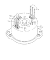
図1に示すように、ブラシレスモータ1のモータケース2は、有底の筒状ハウジング3と、その筒状ハウジング3のフロント側の開口部を閉塞するフロントカバー4とで形成されている。また、筒状ハウジング3のリア側のリアカバー壁3aには、収容ボックス5が取着されている。
Hereinafter, an embodiment in which the present invention is embodied in a brushless motor will be described with reference to FIGS.
As shown in FIG. 1, the
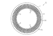
筒状ハウジング3の内周面には、図2〜図5に示すステータ6が固定されている。ステータ6は、コア7を備え、そのコア7は、円筒部8と該円筒部8から径方向内側に延びて周方向に複数設けられたティース9とを有する。
A
本実施形態では、ティース9は、図5に示すように、60個形成されている。従って、ティース9間に形成されるスロットSは60個形成され、その60個のスロットSは、円筒部8の中心軸線から見て6度の等角度の間隔に配置形成されている。尚、説明の便宜上、個々のスロットSについて個々に特定する必要があるとき、60個のスロットSの周方向に連続した番号であるスロット番号「1」〜「60」を付けて説明する。
In the present embodiment, 60
図6及び図7に示すように、各スロットSには、U相、V相、W相のからなる3相巻線が巻回されている。図6及び図7では、周方向にスロットSのスロット番号「1」〜「60」を付している。 As shown in FIGS. 6 and 7, a three-phase winding composed of a U phase, a V phase, and a W phase is wound around each slot S. 6 and 7, slot numbers “1” to “60” of the slots S are given in the circumferential direction.
各スロットSには、軸線方向の一側(リアカバー壁3a側)から他側(フロントカバー4側)に向かって図8に示す定形状に形成されたU字状のセグメントSGが挿入される。そして、各セグメントSG同士を所定の規則で接続することによって、3相Y結線のSC巻線を形成している。
A U-shaped segment SG formed in a fixed shape shown in FIG. 8 is inserted into each slot S from one side in the axial direction (rear cover wall 3a side) to the other side (
図8に示すように、スロットSに挿入する前のセグメントSGは、U字形状をした波巻用の外側導体OSと重ね巻用の内側導体ISを有している。外側導体OSと内側導体ISは、表面が絶縁材で被膜され、外側導体OSと内側導体ISが電気的に導通しないようになっている。 As shown in FIG. 8, the segment SG before being inserted into the slot S has a U-shaped outer conductor OS for wave winding and an inner conductor IS for lap winding. The outer conductor OS and the inner conductor IS are coated with an insulating material so that the outer conductor OS and the inner conductor IS are not electrically connected.
外側導体OSは、第1導体部OSiと第4導体部OSoを有し、第1導体部OSiの基端部と第4導体部OSoの基端部とが連結導体部OScにて連結されている。第1導体部OSiと第4導体部OSoは、互いに連結導体部OScから離間する方向に拡開するように屈曲形成させた後、互いに平行となるように屈曲形成されている。 The outer conductor OS has a first conductor part OSi and a fourth conductor part OSo, and the base end part of the first conductor part OSi and the base end part of the fourth conductor part OSo are connected by the connecting conductor part OSc. Yes. The first conductor portion OSi and the fourth conductor portion OSo are bent so as to expand in a direction away from the connecting conductor portion OSc, and then bent so as to be parallel to each other.
内側導体ISは、外側導体OSの内側に囲まれて配置される。内側導体ISは、第2導体部ISiと第3導体部ISoを有し、第2導体部ISiの基端部と第3導体部ISoの基端部とが連結導体部IScにて連結されている。第2導体部ISiは、連結導体部IScから外側導体OSの第1導体部OSiに沿って屈曲形成されている。第3導体部ISoは、連結導体部IScから外側導体OSの第4導体部OSoに沿って屈曲形成されている。 The inner conductor IS is disposed so as to be surrounded by the outer conductor OS. The inner conductor IS has a second conductor portion ISi and a third conductor portion ISo, and the base end portion of the second conductor portion ISi and the base end portion of the third conductor portion ISo are connected by the connecting conductor portion ISc. Yes. The second conductor portion ISi is bent from the connecting conductor portion ISc along the first conductor portion OSi of the outer conductor OS. The third conductor part ISo is bent from the connecting conductor part ISc along the fourth conductor part OSo of the outer conductor OS.
そして、外側導体OSの内側に内側導体ISを配置することによって、スロットSに挿入する前のU字形状のセグメントSGが形成される。このように形成されたセグメントSGついて、外側及び内側導体OS,ISの第1及び第2導体部OSi,ISiは同一のスロットSに挿入され、外側及び内側導体OS,ISの第4及び第3導体部OSo,ISoは前記第1及び第2導体部OSi,ISiとは異なる隣接する同相のスロットSに挿入される。 The U-shaped segment SG before being inserted into the slot S is formed by arranging the inner conductor IS inside the outer conductor OS. For the segment SG thus formed, the first and second conductor portions OSi, ISi of the outer and inner conductors OS, IS are inserted into the same slot S, and the fourth and third of the outer and inner conductors OS, IS are inserted. The conductor portions OSo and ISo are inserted into adjacent in-phase slots S different from the first and second conductor portions OSi and ISi.
例えば、外側及び内側導体OS,ISについて、第1及び第2導体部OSi,ISiをスロット番号「60」のスロットSに挿入したとき、第4及び第3導体部OSo,ISoをスロット番号「6」のスロットSに挿入するようになっている。つまり、1つのセグメントSGの第1及び第2導体部OSi,ISiと第4及び第3導体部OSo,ISoは、6スロットピッチの間隔をおいて挿入されることになる。 For example, when the first and second conductor portions OSi, ISi are inserted into the slot S with the slot number “60” for the outer and inner conductors OS, IS, the fourth and third conductor portions OSo, ISo are assigned with the slot number “6”. Is inserted into the slot S. That is, the first and second conductor portions OSi, ISi and the fourth and third conductor portions OSo, ISo of one segment SG are inserted with an interval of 6 slot pitches.
そして、第4及び第3導体部OSo,ISoを挿入したスロット番号「6」のスロットSには、隣のセグメントSGの外側及び内側導体OS,ISの第1及び第2導体部OSi,ISiが挿入される。さらに、その隣のセグメントSGは、自身の外側及び内側導体OS,ISの第4及び第3導体部OSo,ISoをスロットS番号「12」のスロットSに挿入させる。 In the slot S with the slot number “6” into which the fourth and third conductor portions OSo and ISo are inserted, the first and second conductor portions OSi and ISi of the outer and inner conductors OS and IS of the adjacent segment SG are provided. Inserted. Further, the adjacent segment SG inserts the fourth and third conductor portions OSo, ISo of its outer and inner conductors OS, IS into the slot S of the slot S number “12”.
順次同様な方法で、リアカバー壁3a側からフロントカバー4側に向かってセグメントSGをスロットSに挿入する。これによって、10個目のセグメントSGの外側及び内側導体OS,ISの第1及び第2導体部OSi,ISiが、スロット番号「60」のスロットSに挿入されて1周する。周回した10個のセグメントSGを互いに接続することによって1相分の巻線が形成される。
The segments SG are sequentially inserted into the slots S from the rear cover wall 3a side to the
従って、スロットSが60個あり6相分の巻線が形成されるため、U相、V相、W相の3相巻線が2つ(第1系統3相巻線と第2系統3相巻線)形成されることになる。ここで、第1系統3相巻線と第2系統3相巻線とをそれぞれ特定して説明するときは、第1系統3相巻線の各相をU1相、V1相、W1相とし、第2系統3相巻線の各相をU2相、V2相、W2相という。なお、スロットSの内周面は、インシュレータ10(図12参照)が形成され、セグメントSGとステータ6のコア7との間を電気的に絶縁している。
Therefore, since there are 60 slots S and 6-phase windings are formed, two U-phase, V-phase, and W-phase three-phase windings (the first three-phase winding and the second three-phase winding) Winding) will be formed. Here, when specifying and explaining the first system three-phase winding and the second system three-phase winding, respectively, the phases of the first system three-phase winding are U1, V1, and W1 phases, Each phase of the second system three-phase winding is referred to as a U2 phase, a V2 phase, and a W2 phase. An insulator 10 (see FIG. 12) is formed on the inner peripheral surface of the slot S, and the segment SG and the
本実施形態では、第1系統3相巻線と第2系統3相巻線の各相の巻線が使用するスロットSが、表1で示すように割り当てられている。 In this embodiment, the slots S used by the windings of each phase of the first system three-phase winding and the second system three-phase winding are assigned as shown in Table 1.

そして、第1系統3相巻線のV1相は、第1系統3相巻線のU1相の巻線に対して、2スロットピッチずれた各スロットSに巻線が巻回(セグメントSGが挿入)されることがわかる。また、第1系統3相巻線のW1相は、第1系統3相巻線のU1相の巻線に対して、4スロットピッチずれた各スロットSに巻線が巻回(セグメントSGが挿入)されることがわかる。 The V1 phase of the first system three-phase winding is wound in each slot S shifted by 2 slot pitches relative to the U1 phase winding of the first system three-phase winding (segment SG is inserted). ) In addition, the W1 phase of the first system three-phase winding is wound in each slot S shifted by 4 slot pitches relative to the U1 phase winding of the first system three-phase winding (segment SG is inserted). )
ちなみに、第2系統3相巻線のU2相は、第1系統3相巻線のU1相の巻線に対して、1スロットピッチずれて、スロット番号が「1」、「7」、「13」、「19」、「25」、「31」、「37」、「43」、「49」、「55」のスロットSに巻線が巻回(セグメントSGが挿入)されることがわかる。 By the way, the U2 phase of the second system three-phase winding is shifted by one slot pitch with respect to the U1 phase winding of the first system three-phase winding, and the slot numbers are “1”, “7”, “13”. ”,“ 19 ”,“ 25 ”,“ 31 ”,“ 37 ”,“ 43 ”,“ 49 ”,“ 55 ”, the winding is wound (segment SG is inserted).
同様に、第2系統3相巻線のV2相は、第2系統3相巻線のU2相の巻線に対して、2スロットピッチずれた各スロットSに巻線が巻回(セグメントSGが挿入)されることがわかる。また、第2系統3相巻線のW2相は、第2系統3相巻線のU2相の巻線に対して、4スロットピッチずれた各スロットSに巻線が巻回(セグメントSGが挿入)されることがわかる。 Similarly, the V2 phase of the second system three-phase winding is wound in each slot S shifted by 2 slot pitches relative to the U2 phase winding of the second system three-phase winding (segment SG is It can be seen that In addition, the W2 phase of the second system three-phase winding is wound in each slot S shifted by 4 slot pitches relative to the U2 phase winding of the second system three-phase winding (segment SG is inserted). )
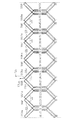
そして、上記の条件で60個全てのスロットSに、図8に示す波巻用の外側導体OSと重ね巻用の内側導体ISからなるセグメントSGを挿通する。続いて、全てのスロットSにセグメントSGについて、図9に示すように、外側導体OS及び内側導体ISを折り曲げ形成して各相の巻線を形成する。 Then, the segment SG including the wave winding outer conductor OS and the lap winding inner conductor IS shown in FIG. 8 is inserted into all 60 slots S under the above conditions. Subsequently, as shown in FIG. 9, the outer conductor OS and the inner conductor IS are bent and formed in all slots S for the segments SG to form the windings of the respective phases.
波巻用の外側導体OSの折り曲げは、スロットSから突出した部分の第1導体部OSi及び第4導体部OSoを互いに離間する方向に折り曲げる。そして、外側導体OSの第1及び第4導体部OSi,OSoについて、スロットSから突出し互いに離間する方向に折り曲げられた部分を第1及び第4溶接部OWi,OWoという。 The outer conductor OS for wave winding is bent in a direction in which the first conductor portion OSi and the fourth conductor portion OSo protruding from the slot S are separated from each other. And about the 1st and 4th conductor part OSi and OSo of the outer side conductor OS, the part which protruded from the slot S and was bent in the direction mutually spaced apart is called 1st and 4th welding part OWi and OWo.
一方、重ね巻用の内側導体ISの折り曲げは、スロットSから突出した部分の第2導体部ISi及び第3導体部ISoを互いに近づく方向に折り曲げる。そして、内側導体ISの第2及び第3導体部ISi,ISoについて、スロットSから突出し互いに近づく方向に折り曲げられた部分を第2及び第3溶接部IWi,IWoという。
(第1系統3相巻線)
次に、第1系統3相巻線について説明する。
On the other hand, the folding of the inner conductor IS for lap winding is performed by bending the second conductor portion ISi and the third conductor portion ISo of the portion protruding from the slot S so as to approach each other. And about the 2nd and 3rd conductor part ISi, ISo of the inner side conductor IS, the part which protruded from the slot S and was bent in the direction which mutually approaches is called 2nd and 3rd weld part IWi, IWo.
(First system three-phase winding)
Next, the first system three-phase winding will be described.
ここで、10個のセグメントSGを使って、第1系統3相巻線の内のU1相の巻線の巻線方法について、図10及び図11に従って説明する。
第1系統のU1相の巻線に使用されるスロットSは、表1に示すスロット番号のスロットSが割り当てられ、10個のセグメントSG1〜SG10が使用される。
Here, a winding method of the U1-phase winding of the first system three-phase winding using the ten segments SG will be described with reference to FIGS. 10 and 11.
Slots S having slot numbers shown in Table 1 are assigned to slots S used for the U1 phase winding of the first system, and ten segments SG1 to SG10 are used.
ここで、1個目のセグメントSG1はスロット番号「60」及び「6」のスロットSに挿入される。2個目のセグメントSG2はスロット番号「6」及び「12」のスロットSに挿入される。3個目のセグメントSG3はスロット番号「12」及び「18」のスロットSに挿入される。4個目のセグメントSG4はスロット番号「18」及び「24」のスロットSに挿入される。5個目のセグメントSG5はスロット番号「24」及び「30」のスロットSに挿入される。 Here, the first segment SG1 is inserted into slot S with slot numbers “60” and “6”. The second segment SG2 is inserted into slot S with slot numbers “6” and “12”. The third segment SG3 is inserted into slot S with slot numbers “12” and “18”. The fourth segment SG4 is inserted into slot S with slot numbers “18” and “24”. The fifth segment SG5 is inserted into slot S with slot numbers “24” and “30”.
さらに、6個目のセグメントSG6はスロット番号「30」及び「36」のスロットSに挿入される。7個目のセグメントSG7はスロット番号「36」及び「42」のスロットSに挿入される。8個目のセグメントSG8はスロット番号「42」及び「48」のスロットSに挿入される。9個目のセグメントSG9はスロット番号「48」及び「54」のスロットSに挿入される。10個目のセグメントSG10はスロット番号「54」及び「60」のスロットSに挿入される。 Further, the sixth segment SG6 is inserted into slot S with slot numbers “30” and “36”. The seventh segment SG7 is inserted into slot S with slot numbers “36” and “42”. The eighth segment SG8 is inserted into slot S with slot numbers “42” and “48”. The ninth segment SG9 is inserted into slot S with slot numbers “48” and “54”. The tenth segment SG10 is inserted into slot S with slot numbers “54” and “60”.
なお、セグメントSG1〜SG10を各スロットSに挿入する際、後続するセグメントが所定のスロットSに挿入し易いように、外側導体OSの連結導体部OSc及び内側導体ISの連結導体部IScを斜めに捻るように、図3に示すように、折り曲げ形成して挿入している。 When inserting the segments SG1 to SG10 into each slot S, the connecting conductor portion OSc of the outer conductor OS and the connecting conductor portion ISc of the inner conductor IS are inclined so that the subsequent segment can be easily inserted into the predetermined slot S. As shown in FIG. 3, it is bent and inserted so as to be twisted.
今、図10に示すように、スロット番号「60」及び「6」には、U1相用の1個目のセグメントSG1が挿入されている。これによって、スロット番号「60」のスロットSには、内側導体ISの第2導体部ISiと外側導体OSの第1導体部OSiが配置され、スロット番号「6」のスロットSには、内側導体ISの第3導体部ISoと外側導体OSの第4導体部OSoが配置されている。 As shown in FIG. 10, the first segment SG1 for the U1 phase is inserted in the slot numbers “60” and “6”. Accordingly, the second conductor portion ISi of the inner conductor IS and the first conductor portion OSi of the outer conductor OS are arranged in the slot S of the slot number “60”, and the inner conductor is inserted in the slot S of the slot number “6”. A third conductor portion ISo of IS and a fourth conductor portion OSo of the outer conductor OS are arranged.
スロット番号「6」及び「12」には、U1相用の2個目のセグメントSG2が挿入されている。これによって、スロット番号「6」のスロットSには、内側導体ISの第2導
体部ISiと外側導体OSの第1導体部OSiが配置され、スロット番号「12」のスロットSには、内側導体ISの第3導体部ISoと外側導体OSの第4導体部OSoが配置されている。
In the slot numbers “6” and “12”, the second segment SG2 for the U1 phase is inserted. Accordingly, the second conductor portion ISi of the inner conductor IS and the first conductor portion OSi of the outer conductor OS are arranged in the slot S of the slot number “6”, and the inner conductor is inserted in the slot S of the slot number “12”. A third conductor portion ISo of IS and a fourth conductor portion OSo of the outer conductor OS are arranged.
このとき、スロット番号「6」のスロットSには、1個目のセグメントSG1の内側及び外側導体IS,OSの第3及び第4導体部ISo,OSoが配置され、2個目のセグメントSG2の外側及び内側導体OS,ISの第1及び第2導体部OSi,ISiが配置される。 At this time, in the slot S of the slot number “6”, the third and fourth conductor portions ISo and OSo of the inner and outer conductors IS and OS of the first segment SG1 are arranged, and the second segment SG2 The first and second conductor portions OSi, ISi of the outer and inner conductors OS, IS are arranged.
つまり、図12に示すように、スロットSに、径方向に内側から第1導体部OSi、第2導体部ISi、第3導体部ISo、第4導体部OSoの順に、4層構造となって配置されている。そして、1個目のセグメントSG1の外側導体OS(スロット番号「6」を貫挿した)の第4溶接部OWoと、2個目のセグメントSG2の内側導体IS(スロット番号「12」を貫挿した)の第3溶接部IWoとを溶接する。 That is, as shown in FIG. 12, the slot S has a four-layer structure in the order of the first conductor portion OSi, the second conductor portion ISi, the third conductor portion ISo, and the fourth conductor portion OSo from the inside in the radial direction. Has been placed. Then, the fourth welded portion OWo of the outer conductor OS (inserted through the slot number “6”) of the first segment SG1 and the inner conductor IS (slot number “12” of the second segment SG2 are inserted). The third welded portion IWo is welded.
スロット番号「12」及び「18」には、U1相用の3個目のセグメントSG3が挿入されている。これによって、スロット番号「12」のスロットSには、内側導体ISの第2導体部ISiと外側導体OSの第1導体部OSiが配置され、スロット番号「18」のスロットSには、内側導体ISの第3導体部ISoと外側導体OSの第4導体部OSoが配置されている。 In the slot numbers “12” and “18”, the third segment SG3 for the U1 phase is inserted. Accordingly, the second conductor portion ISi of the inner conductor IS and the first conductor portion OSi of the outer conductor OS are arranged in the slot S of the slot number “12”, and the inner conductor is inserted in the slot S of the slot number “18”. A third conductor portion ISo of IS and a fourth conductor portion OSo of the outer conductor OS are arranged.
このとき、スロット番号「12」のスロットSには、2個目のセグメントSG2の内側及び外側導体IS,OSの第3及び第4導体部ISo,OSoが配置され、3個目のセグメントSG3の外側及び内側導体OS,ISの第1及び第2導体部OSi,ISiが配置される。そして、2個目のセグメントSG2の外側導体OS(スロット番号「12」を貫挿した)の第4溶接部OWoと、3個目のセグメントSG3の内側導体IS(スロット番号「18」を貫挿した)oの第3溶接部IWoとを溶接する。 At this time, the third and fourth conductor portions ISo, OSo of the inner and outer conductors IS, OS of the second segment SG2 are arranged in the slot S of the slot number “12”, and the third segment SG3 The first and second conductor portions OSi, ISi of the outer and inner conductors OS, IS are arranged. Then, the fourth welded portion OWo of the outer conductor OS (inserted through the slot number “12”) of the second segment SG2 and the inner conductor IS (slot number “18” of the third segment SG3 are inserted). A) Welding the third welded part IWo of o.
さらにまた、2個目のセグメントSG2の内側導体IS(スロット番号「6」を貫挿した)の第2溶接部IWiと、3個目のセグメントSG3の外側導体OS(スロット番号「12」を貫挿した)の第4溶接部OWoとを溶接する。以後、同様な、4〜10個のセグメントSG4〜SG10について、同様な工程を繰り返すことによって、図10及び図11に示すU1相の巻線が形成される。 Furthermore, the second welded portion IWi of the inner conductor IS (inserted through the slot number “6”) of the second segment SG2 and the outer conductor OS (slot number “12” of the third segment SG3). The fourth welded portion OWo of (inserted) is welded. Thereafter, the same process is repeated for the similar 4 to 10 segments SG4 to SG10, whereby the U1 phase winding shown in FIGS. 10 and 11 is formed.
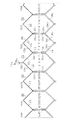
ここで、隣接するセグメントSG同士の溶接について説明する。
なお、説明の便宜上、スロット番号「60」及び「6」のスロットSに挿入される1個目のセグメントSG1に対して、隣接する2個目のセグメントSG2と10個目のセグメントSG10との間の溶接について説明する。
Here, welding of adjacent segments SG will be described.
For convenience of explanation, between the adjacent second segment SG2 and the tenth segment SG10 with respect to the first segment SG1 inserted into the slot S with slot numbers “60” and “6”. Next, welding will be described.
図13に示すように、1個目のセグメントSG1の外側導体OSの第1溶接部OWiは、その先端面S1が10個目のセグメントSG10の内側導体ISの第2溶接部IWiの先端面S2との間で溶接部材B1で溶接され、且つ、電気的に接続されている。また、1個目のセグメントSG1の内側導体ISの第2溶接部IWiは、その先端面S2が2個目のセグメントSG2の外側導体OSの第1溶接部OWiの先端面S1との間で溶接部材B1で溶接され、且つ、電気的に接続されている。 As shown in FIG. 13, the first welded portion OWi of the outer conductor OS of the first segment SG1 has a distal end surface S1 of the second welded portion IWi of the inner conductor IS of the tenth segment SG10. Are welded with a welding member B1 and electrically connected to each other. Further, the second welded portion IWi of the inner conductor IS of the first segment SG1 is welded between the distal end surface S2 of the first welded portion OWi of the outer conductor OS of the second segment SG2. It is welded and electrically connected by the member B1.
さらに、1個目のセグメントSG1の内側導体ISの第3溶接部IWoは、その先端面S3が10個目のセグメントSG10の外側導体OSの第4溶接部OWoの先端面S4との間で溶接部材B2で溶接され、且つ、電気的に接続されている。 Further, the third welded portion IWo of the inner conductor IS of the first segment SG1 is welded between the tip surface S3 and the tip surface S4 of the fourth welded portion OWo of the outer conductor OS of the tenth segment SG10. It is welded and electrically connected by the member B2.
さらにまた、1個目のセグメントSG1の外側導体OSの第4溶接部OWoは、その先端面S4が2個目のセグメントSG2の内側導体ISの第3溶接部IWoの先端面S3との間で溶接部材B2で溶接され、且つ、電気的に接続されている。 Furthermore, the fourth welded portion OWo of the outer conductor OS of the first segment SG1 has a tip surface S4 between the tip surface S3 of the third welded portion IWo of the inner conductor IS of the second segment SG2. It is welded by the welding member B2 and is electrically connected.
第1系統3相巻線の他のV1相,W1相の巻線もU1相の巻線と同様な方法で巻回される。また、第1系統3相巻線は3相Y結線で構成されている。そして、各相の巻線について中性点N1(図14参照)と接続する中性点端子T0u,T0v,T0w及び電力を受電する電力受電端子T1u,T1v,T1wを決めている。 The other V1-phase and W1-phase windings of the first system three-phase winding are wound in the same manner as the U1-phase winding. Further, the first system three-phase winding is constituted by a three-phase Y connection. Then, neutral point terminals T0u, T0v, T0w connected to the neutral point N1 (see FIG. 14) and electric power receiving terminals T1u, T1v, T1w for receiving electric power are determined for each phase winding.
なお、第1系統3相巻線の各相の巻線について、各セグメントSGは、全て溶接端が軸方向において一様な高さに揃うように溶接されている。そして、各セグメントSGのフロント側の先端とフロントカバー4の間隔は同じになるように形成されている。
(中性点端子及び電力受電端子の設定)
図6に示すように、本実施形態では、U1相の巻線について、1個目のセグメントSG1の外側導体OS及び内側導体ISのリアカバー壁3a側に位置する連結導体部OSc,IScを分離する。
In addition, regarding the windings of each phase of the first system three-phase winding, all the segments SG are welded so that the weld ends are aligned at a uniform height in the axial direction. The distance between the front end of each segment SG and the
(Setting of neutral point terminal and power receiving terminal)
As shown in FIG. 6, in the present embodiment, the U1-phase winding is separated from the outer conductor OS of the first segment SG1 and the connecting conductor portions OSc and ISc located on the rear cover wall 3a side of the inner conductor IS. .
ここで、外側導体OSの連結導体部OScの分離端であって同外側導体OSの第4導体部OSoに繋がる方と、内側導体ISの連結導体部IScの分離端であって同内側導体ISの第2導体部ISiに繋がる方とを接続する。 Here, the separation end of the connection conductor portion OSc of the outer conductor OS and the connection end to the fourth conductor portion OSo of the outer conductor OS, and the separation end of the connection conductor portion ISc of the inner conductor IS and the same inner conductor IS. The one connected to the second conductor portion ISi is connected.
そして、外側導体OSの連結導体部OScの分離端であって同外側導体OSの第1導体部OSiに繋がる方を、U1相の中性点端子T0uとしている。一方、内側導体ISの連結導体部IScの分離端であって同内側導体ISの第3導体部ISoに繋がる方を、U1相の電力受電端子T1uとしている。 The one that is connected to the first conductor portion OSi of the outer conductor OS and that is the separation end of the connecting conductor portion OSc of the outer conductor OS is defined as a neutral point terminal T0u of the U1 phase. On the other hand, the one connected to the third conductor portion ISo of the inner conductor IS and the separated end of the connecting conductor portion ISc of the inner conductor IS is defined as a U1-phase power receiving terminal T1u.
つまり、中性点端子T0uは、スロット番号「60」のスロットS内の径方向において最も内側に配置された外側導体OSの第1導体部OSiから引き出された端子である。また、電力受電端子T1uは、スロット番号「6」のスロットS内の径方向において3番目に外側の位置に配置された内側導体ISの第3導体部ISoから引き出された端子である。 That is, the neutral point terminal T0u is a terminal drawn out from the first conductor portion OSi of the outer conductor OS arranged on the innermost side in the radial direction in the slot S of the slot number “60”. The power receiving terminal T1u is a terminal drawn out from the third conductor portion ISo of the inner conductor IS disposed at the third outer position in the radial direction in the slot S of the slot number “6”.
従って、電力受電端子T1uは、中性点端子T0uよりスロットS内の径方向において外側に配置される。
また、図6に示すように、V1相の巻線について、スロット番号「56」及び「2」に挿入されたセグメントSGの外側導体OS及び内側導体ISの連結導体部OSc,IScを分離する。
Therefore, the power receiving terminal T1u is disposed outside the neutral point terminal T0u in the radial direction in the slot S.
Further, as shown in FIG. 6, for the V1 phase winding, the outer conductor OS of the segment SG and the connecting conductor portions OSc and ISc of the inner conductor IS inserted in the slot numbers “56” and “2” are separated.
同様に、外側導体OSの連結導体部OScの分離端であって同外側導体OSの第4導体部OSoに繋がる方と、内側導体ISの連結導体部IScの分離端であって同内側導体ISの第2導体部ISiに繋がる方とを接続する。 Similarly, the separated end of the connecting conductor portion OSc of the outer conductor OS and the fourth conductor portion OSo of the outer conductor OS, and the separated end of the connecting conductor portion ISc of the inner conductor IS and the inner conductor IS. The one connected to the second conductor portion ISi is connected.
そして、外側導体OSの連結導体部OScの分離端であって同外側導体OSの第1導体部OSiに繋がる方を、V1相の中性点端子T0vとしている。一方、内側導体ISの連結導体部IScの分離端であって同内側導体ISの第3導体部ISoに繋がる方を、V1相の電力受電端子T1vとしている。 The one that is connected to the first conductor portion OSi of the outer conductor OS and that is the separation end of the connecting conductor portion OSc of the outer conductor OS is defined as a neutral point terminal T0v of the V1 phase. On the other hand, the one connected to the third conductor portion ISo of the inner conductor IS and the separated end of the connecting conductor portion ISc of the inner conductor IS is defined as a V1 phase power receiving terminal T1v.
つまり、中性点端子T0vは、スロット番号「56」のスロットS内の径方向において最も内側に配置された外側導体OSの第1導体部OSiから引き出された端子である。また、電力受電端子T1vは、スロット番号「2」のスロットS内の径方向において3番目に外側の位置に配置された内側導体ISの第3導体部ISoから引き出された端子である。 That is, the neutral point terminal T0v is a terminal drawn out from the first conductor portion OSi of the outer conductor OS arranged on the innermost side in the radial direction in the slot S of the slot number “56”. The power receiving terminal T1v is a terminal drawn from the third conductor portion ISo of the inner conductor IS arranged at the third outer position in the radial direction in the slot S of the slot number “2”.
従って、電力受電端子T1vは、中性点端子T0vよりスロットS内の径方向において外側に配置される。
また、図6に示すように、W1相の巻線について、スロット番号「52」及び「58」に挿入されたセグメントSGの外側導体OS及び内側導体ISの連結導体部OSc,IScを分離する。
Therefore, the power receiving terminal T1v is arranged outside in the radial direction in the slot S from the neutral point terminal T0v.
Further, as shown in FIG. 6, for the W1 phase winding, the outer conductor OS of the segment SG and the connecting conductor portions OSc and ISc of the inner conductor IS inserted in the slot numbers “52” and “58” are separated.
同様に、外側導体OSの連結導体部OScの分離端であって同外側導体OSの第4導体部OSoに繋がる方と、内側導体ISの連結導体部IScの分離端であって同内側導体ISの第2導体部ISiに繋がる方とを接続する。 Similarly, the separated end of the connecting conductor portion OSc of the outer conductor OS and the fourth conductor portion OSo of the outer conductor OS, and the separated end of the connecting conductor portion ISc of the inner conductor IS and the inner conductor IS. The one connected to the second conductor portion ISi is connected.
そして、外側導体OSの連結導体部OScの分離端であって同外側導体OSの第1導体部OSiに繋がる方を、W1相の中性点端子T0wとしている。一方、内側導体ISの連結導体部IScの分離端であって同内側導体ISの第3導体部ISoに繋がる方を、W1相の電力受電端子T1wとしている。 The one that is connected to the first conductor part OSi of the outer conductor OS and that is the separation end of the connection conductor part OSc of the outer conductor OS is defined as a neutral point terminal T0w of the W1 phase. On the other hand, the W1 phase power receiving terminal T1w is the separation end of the connecting conductor portion ISc of the inner conductor IS and the one connected to the third conductor portion ISo of the inner conductor IS.
つまり、中性点端子T0wは、スロット番号「52」のスロットS内の径方向において最も内側に配置された外側導体OSの第1導体部OSiから引き出された端子である。また、電力受電端子T1wは、スロット番号「58」のスロットS内の径方向において3番目に外側の位置に配置された内側導体ISの第3導体部ISoから引き出された端子である。 That is, the neutral point terminal T0w is a terminal drawn out from the first conductor portion OSi of the outer conductor OS arranged on the innermost side in the radial direction in the slot S of the slot number “52”. The power receiving terminal T1w is a terminal drawn from the third conductor portion ISo of the inner conductor IS arranged at the third outer position in the radial direction in the slot S of the slot number “58”.
従って、電力受電端子T1wは、中性点端子T0wよりスロットS内の径方向において外側に配置される。
これによって、各相の電力受電端子T1u,T1v,T1wは、スロットS内の径方向において3番目に外側の位置にそれぞれ配置され、各相の中性点端子T0u,T0v,T0wは、スロットS内の径方向において最も内側にそれぞれ配置される。しかも、各相の電力受電端子T1u,T1v,T1wは互いに短い位置に配置されている。同様に、各相の中性点端子T0u,T0v,T0wも、各相の電力受電端子T1u,T1v,T1wの内側であって互いに短い位置に配置されている。
Therefore, the power receiving terminal T1w is disposed outside the neutral point terminal T0w in the radial direction in the slot S.
Thereby, the power receiving terminals T1u, T1v, T1w of each phase are respectively arranged at the third outer positions in the radial direction in the slot S, and the neutral point terminals T0u, T0v, T0w of the respective phases are arranged in the slot S. They are arranged on the innermost side in the inner radial direction. In addition, the power receiving terminals T1u, T1v, T1w of each phase are arranged at short positions. Similarly, the neutral point terminals T0u, T0v, T0w of each phase are also arranged at short positions inside the power receiving terminals T1u, T1v, T1w of each phase.
従って、各相の中性点端子T0u,T0v,T0wを互いに接続する中性線L1nは、各相の電力受電端子T1u,T1v,T1wより内側に配置される。その結果、図3に示すように、各相の電力受電端子T1u,T1v,T1wから引き出される各引出線L1u,L1v,L1wは、中性線L1nよりも外側に配置される。 Therefore, the neutral line L1n that connects the neutral point terminals T0u, T0v, and T0w of each phase is disposed inside the power receiving terminals T1u, T1v, and T1w of each phase. As a result, as shown in FIG. 3, the lead lines L1u, L1v, and L1w drawn from the power receiving terminals T1u, T1v, and T1w of the respective phases are arranged outside the neutral line L1n.
そして、各相の中性点端子T0u,T0v,T0wを互いに中性線L1nにて接続し、各相の電力受電端子T1u,T1v,T1wを受電端とすれば、第1系統の3相Y結線の巻線が形成され、図14に示すような電気回路が形成される。なお、図中、「L1」は、電力受電端子T1u,T1v,T1wからそれぞれの巻線が周回し、それぞれ外側導体OSの連結導体部OScの分離端と内側導体ISの連結導体部IScの分離端との接続点までのインダクタンスを示す。また。「L2」は、それぞれその外側導体OSの連結導体部OScの分離端と内側導体ISの連結導体部IScの分離端との接続点から、それぞれの各中性点端子T0u,T0v,T0wまでのインダクタンスを示す。
(第2系統3相巻線)
次に、第2系統3相巻線について説明する。
Then, if the neutral point terminals T0u, T0v, T0w of each phase are connected to each other by a neutral line L1n, and the power receiving terminals T1u, T1v, T1w of each phase are the receiving ends, the three-phase Y of the first system Wires for connection are formed, and an electric circuit as shown in FIG. 14 is formed. In the figure, “L1” indicates that the respective windings circulate from the power receiving terminals T1u, T1v, T1w, and the separation end of the connection conductor portion OSc of the outer conductor OS and the connection conductor portion ISc of the inner conductor IS are separated. Indicates the inductance to the connection point with the end. Also. “L2” is from the connection point between the separation end of the connection conductor portion OSc of the outer conductor OS and the separation end of the connection conductor portion ISc of the inner conductor IS to each neutral point terminal T0u, T0v, T0w. Indicates inductance.
(Second system, three-phase winding)
Next, the second system three-phase winding will be described.
第2系統3相巻線は、第1系統3相巻線と同様に3相Y結線である。そして、第2系統の3相各巻線は、第1系統の対応する3相各巻線と1スロットピッチずれて各スロットSにそれぞれ巻回される。 The second system three-phase winding is a three-phase Y-connection as in the first system three-phase winding. Then, each of the three-phase windings of the second system is wound around each of the slots S with a shift of one slot pitch from each of the corresponding three-phase windings of the first system.
従って、図15、図16に示すように、第2系統のU2相巻線は、第1系統のU1相巻線に対して、1スロットピッチずれて各スロットSにそれぞれ巻回される。
第2系統のU2相の巻線に使用されるスロットSは、表1に示すスロット番号のスロットSが割り当てられ、10個のセグメントSG1a〜SG10aが使用される。
Accordingly, as shown in FIGS. 15 and 16, the second U2-phase winding is wound around each slot S with a one-slot pitch shift from the first U1-phase winding.
Slots S having slot numbers shown in Table 1 are assigned to slots S used for the U2 phase winding of the second system, and ten segments SG1a to SG10a are used.
ここで、1個目のセグメントSG1aはスロット番号「1」及び「7」のスロットSに挿入される。2個目のセグメントSG2aはスロット番号「7」及び「13」のスロットSに挿入される。3個目のセグメントSG3aはスロット番号「13」及び「19」のスロットSに挿入される。4個目のセグメントSG4aはスロット番号「19」及び「25」のスロットSに挿入される。5個目のセグメントSG5aはスロット番号「25」及び「31」のスロットSに挿入される。 Here, the first segment SG1a is inserted into the slot S with slot numbers “1” and “7”. The second segment SG2a is inserted into slot S with slot numbers “7” and “13”. The third segment SG3a is inserted into slot S with slot numbers “13” and “19”. The fourth segment SG4a is inserted into slot S with slot numbers “19” and “25”. The fifth segment SG5a is inserted into slot S with slot numbers “25” and “31”.
さらに、6個目のセグメントSG6aはスロット番号「31」及び「37」のスロットSに挿入される。7個目のセグメントSG7aはスロット番号「37」及び「43」のスロットSに挿入される。8個目のセグメントSG8aはスロット番号「43」及び「49」のスロットSに挿入される。9個目のセグメントSG9aはスロット番号「49」及び「55」のスロットSに挿入される。10個目のセグメントSG10aはスロット番号「55」及び「1」のスロットSに挿入される。 Further, the sixth segment SG6a is inserted into the slot S with slot numbers “31” and “37”. The seventh segment SG7a is inserted into slot S with slot numbers “37” and “43”. The eighth segment SG8a is inserted into slot S with slot numbers “43” and “49”. The ninth segment SG9a is inserted into slot S with slot numbers “49” and “55”. The tenth segment SG10a is inserted into slot S with slot numbers “55” and “1”.
そして、第1系統のU1相巻線と同様に、各セグメントSG1a〜SG10aが結線されて第2系統のU2相の巻線が形成される。また、第2系統3相巻線の他のV2相,W2相の巻線もU2相の巻線と同様な方法で巻回される。 Similarly to the U1 phase winding of the first system, the segments SG1a to SG10a are connected to form the U2 phase winding of the second system. The other V2-phase and W2-phase windings of the second system three-phase windings are also wound in the same manner as the U2-phase windings.
さらに、第2系統3相巻線も同様に3相Y結線で構成されている。従って、各相の巻線について中性点N2(図17参照)と接続する中性点端子T0ua,T0va,T0wa及び電力を受電する電力受電端子T2u,T2v,T2wを決めている。 Further, the second system three-phase winding is similarly configured with a three-phase Y connection. Therefore, the neutral point terminals T0ua, T0va, T0wa connected to the neutral point N2 (see FIG. 17) and the power receiving terminals T2u, T2v, T2w for receiving power are determined for the windings of each phase.
なお、第2系統3相巻線の各相の巻線について、各セグメントSGの溶接端は、第1系統3相巻線のセグメントSGの溶接部材B1,B2と軸方向において一様に揃うように合わせてあり、図1〜図4に示すように、全てのセグメントSGの溶接部材B1,B2が軸方向において一様に揃うように溶接されている。その結果、全てのセグメントSGのフロント側の先端とフロントカバー4との間隔は同じとなる。
(中性点端子及び電力受電端子の設定)
図6、図7に示すように、本実施形態では、U2相の巻線について、中性点端子T0ua及び電力受電端子T2uは、U1相の中性点端子T0u及び電力受電端子T1uに対して周方向において180度相対向する位置に設けられる。従って、U2相の巻線について、5個目のセグメントSG5aの外側導体OS及び内側導体ISの連結導体部OSc,IScを分離する。
In addition, about the winding of each phase of 2nd system |
(Setting of neutral point terminal and power receiving terminal)
As shown in FIGS. 6 and 7, in the present embodiment, the neutral point terminal T0ua and the power receiving terminal T2u with respect to the U2 phase winding are in relation to the neutral point terminal T0u and the power receiving terminal T1u of the U1 phase. Provided at positions that oppose each other by 180 degrees in the circumferential direction. Therefore, with respect to the U2-phase winding, the outer conductor OS of the fifth segment SG5a and the connecting conductor portions OSc and ISc of the inner conductor IS are separated.
ここで、U1相巻線と同様に、図16に示すように、外側導体OSの連結導体部OScの分離端であって同外側導体OSの第4導体部OSoに繋がる方と、内側導体ISの連結導体部IScの分離端であって同内側導体ISの第2導体部ISiに繋がる方とを接続する。 Here, similarly to the U1-phase winding, as shown in FIG. 16, the one connected to the fourth conductor portion OSo of the outer conductor OS and the separated end of the connecting conductor portion OSc of the outer conductor OS, and the inner conductor IS To the second conductor portion ISi of the inner conductor IS which is the separated end of the connecting conductor portion ISc.
そして、外側導体OSの連結導体部OScの分離端であって同外側導体OSの第1導体部OSiに繋がる方を、U2相の中性点端子T0uaとしている。一方、内側導体ISの連結導体部IScの分離端であって同内側導体ISの第3導体部ISoに繋がる方を、U2相の電力受電端子T2uとしている。 And the direction which is the separation end of the connection conductor part OSc of the outer conductor OS and is connected to the first conductor part OSi of the outer conductor OS is defined as a neutral point terminal T0ua of the U2 phase. On the other hand, the one connected to the third conductor portion ISo of the inner conductor IS and the separated end of the connecting conductor portion ISc of the inner conductor IS is defined as a U2-phase power receiving terminal T2u.
つまり、中性点端子T0uaは、スロット番号「25」のスロットS内の径方向において最も内側に配置された外側導体OSの第1導体部OSiから引き出された端子である。また、電力受電端子T2uは、スロット番号「31」のスロットS内の径方向において3番目に外側に配置された内側導体ISの第3導体部ISoから引き出された端子である。 That is, the neutral point terminal T0ua is a terminal drawn out from the first conductor portion OSi of the outer conductor OS arranged on the innermost side in the radial direction in the slot S of the slot number “25”. Further, the power receiving terminal T2u is a terminal drawn from the third conductor portion ISo of the inner conductor IS arranged third outside in the radial direction in the slot S of the slot number “31”.
従って、電力受電端子T2uは、中性点端子T0uaよりもスロットS内の径方向において外側に配置される。そして、U2相の電力受電端子T2u及び中性点端子T0uaは、それぞれU1相の電力受電端子T1u及び中性点端子T0uに対して、コア7の周方向に180度相対向する位置に配置される。
Therefore, the power receiving terminal T2u is arranged on the outer side in the radial direction in the slot S than the neutral point terminal T0ua. The U2-phase power receiving terminal T2u and the neutral point terminal T0ua are arranged at positions that oppose each other by 180 degrees in the circumferential direction of the
次に、V2相の巻線について、中性点端子T0va及び電力受電端子T2vは、V1相の中性点端子T0v及び電力受電端子T1vに対して周方向において242度相対向する位置に設けられる。従って、図6、図7に示すように、V2相の巻線について、スロット番号「33」及び「39」に挿入されたセグメントSGの外側導体OS及び内側導体ISの連結導体部OSc,IScを分離する。 Next, with respect to the V2-phase winding, the neutral point terminal T0va and the power receiving terminal T2v are provided at positions opposite to the V1 phase neutral point terminal T0v and the power receiving terminal T1v in the circumferential direction by 242 degrees. . Accordingly, as shown in FIGS. 6 and 7, for the V2-phase winding, the outer conductor OS of the segment SG inserted in the slot numbers “33” and “39” and the connecting conductor portions OSc and ISc of the inner conductor IS are provided. To separate.
同様に、外側導体OSの連結導体部OScの分離端であって同外側導体OSの第4導体部OSoに繋がる方と、内側導体ISの連結導体部IScの分離端であって同内側導体ISの第2導体部ISiに繋がる方とを接続する。 Similarly, the separated end of the connecting conductor portion OSc of the outer conductor OS and the fourth conductor portion OSo of the outer conductor OS, and the separated end of the connecting conductor portion ISc of the inner conductor IS and the inner conductor IS. The one connected to the second conductor portion ISi is connected.
そして、外側導体OSの連結導体部OScの分離端であって同外側導体OSの第1導体部OSiに繋がる方を、V2相の中性点端子T0vaとしている。一方、内側導体ISの連結導体部IScの分離端であって同内側導体ISの第3導体部ISoに繋がる方を、V2相の電力受電端子T2vとしている。 Further, the V2 phase neutral point terminal T0va is the separation end of the connecting conductor portion OSc of the outer conductor OS and the one connected to the first conductor portion OSi of the outer conductor OS. On the other hand, the one connected to the third conductor portion ISo of the inner conductor IS and the separation end of the connecting conductor portion ISc of the inner conductor IS is defined as a V2-phase power receiving terminal T2v.
つまり、中性点端子T0vaは、スロット番号「33」のスロットS内の径方向において最も内側に配置された外側導体OSの第1導体部OSiから引き出された端子である。また、電力受電端子T2vは、スロット番号「39」のスロットS内の径方向において3番目に外側の位置に配置された内側導体ISの第3導体部ISoから引き出された端子である。従って、電力受電端子T2vは、中性点端子T0vaよりスロットS内の径方向において外側に配置される。 That is, the neutral point terminal T0va is a terminal drawn out from the first conductor portion OSi of the outer conductor OS arranged on the innermost side in the radial direction in the slot S of the slot number “33”. The power receiving terminal T2v is a terminal drawn from the third conductor portion ISo of the inner conductor IS arranged at the third outer position in the radial direction in the slot S of the slot number “39”. Therefore, the power receiving terminal T2v is disposed outside the neutral point terminal T0va in the radial direction in the slot S.
次に、W2相の巻線について、中性点端子T0wa及び電力受電端子T2wは、W1相の中性点端子T0w及び電力受電端子T1wに対して周方向において138度相対向する位置に設けられる。従って、図6、図7に示すように、W2相の巻線について、スロット番号「29」及び「35」に挿入されたセグメントSGの外側導体OS及び内側導体ISの連結導体部OSc,IScを分離する。 Next, with respect to the W2-phase winding, the neutral point terminal T0wa and the power receiving terminal T2w are provided at positions facing the neutral point terminal T0w and the power receiving terminal T1w in the circumferential direction by 138 degrees in the circumferential direction. . Accordingly, as shown in FIG. 6 and FIG. 7, the outer conductor OS of the segment SG inserted in the slot numbers “29” and “35” and the connecting conductor portions OSc and ISc of the inner conductor IS are arranged in the W2-phase winding. To separate.
同様に、外側導体OSの連結導体部OScの分離端であって同外側導体OSの第4導体部OSoに繋がる方と、内側導体ISの連結導体部IScの分離端であって同内側導体ISの第2導体部ISiに繋がる方とを接続する。 Similarly, the separated end of the connecting conductor portion OSc of the outer conductor OS and the fourth conductor portion OSo of the outer conductor OS, and the separated end of the connecting conductor portion ISc of the inner conductor IS and the inner conductor IS. The one connected to the second conductor portion ISi is connected.
そして、外側導体OSの連結導体部OScの分離端であって同外側導体OSの第1導体部OSiに繋がる方を、W2相の中性点端子T0waとしている。一方、内側導体ISの連結導体部IScの分離端であって同内側導体ISの第3導体部ISoに繋がる方を、W2相の電力受電端子T2wとしている。 Further, the W2 phase neutral point terminal T0wa is connected to the first conductor portion OSi of the outer conductor OS, which is the separation end of the connecting conductor portion OSc of the outer conductor OS. On the other hand, the W2 phase power receiving terminal T2w is the separated end of the connecting conductor portion ISc of the inner conductor IS and connected to the third conductor portion ISo of the inner conductor IS.
つまり、中性点端子T0waは、スロット番号「29」のスロットS内の径方向において最も内側に配置された外側導体OSの第1導体部OSiから引き出された端子である。また、電力受電端子T2wは、スロット番号「35」のスロットS内の径方向において3番目に外側の位置に配置された内側導体ISの第3導体部ISoから引き出された端子である。従って、電力受電端子T2wは、中性点端子T0waよりスロットS内の径方向において外側に配置される。 That is, the neutral point terminal T0wa is a terminal drawn out from the first conductor portion OSi of the outer conductor OS arranged on the innermost side in the radial direction in the slot S of the slot number “29”. The power receiving terminal T2w is a terminal drawn from the third conductor portion ISo of the inner conductor IS disposed at the third outer position in the radial direction in the slot S of the slot number “35”. Therefore, the power receiving terminal T2w is disposed outside the neutral point terminal T0wa in the radial direction in the slot S.
これによって、各相の電力受電端子T2u,T2v,T2wは、スロットS内の径方向において3番目に外側の位置にそれぞれ配置され、各相の中性点端子T0ua,T0va,T0waは、スロットS内の径方向において最も内側にそれぞれ配置される。しかも、各相の電力受電端子T2u,T2v,T2wは互いに短い位置に配置されている。同様に、各相の中性点端子T0ua,T0va,T0waも、各相の電力受電端子T2u,T2v,T2wの内側であって互いに短い位置に配置されている。 Thereby, the power receiving terminals T2u, T2v, T2w of each phase are respectively arranged at the third outer positions in the radial direction in the slot S, and the neutral point terminals T0ua, T0va, T0wa of each phase are arranged in the slot S. They are arranged on the innermost side in the inner radial direction. Moreover, the power receiving terminals T2u, T2v, and T2w for each phase are arranged at short positions. Similarly, the neutral point terminals T0ua, T0va, T0wa of each phase are also arranged at short positions inside the power receiving terminals T2u, T2v, T2w of each phase.
従って、各相の中性点端子T0ua,T0va,T0waを互いに接続する中性線L2nは、各相の電力受電端子T2u,T2v,T2wより内側に配置される。その結果、図3に示すように、各相の電力受電端子T2u,T2v,T2wから引き出される各引出線L2u,L2v,L2wは、中性線L2nより径方向において外側に配置される。 Therefore, the neutral line L2n that connects the neutral point terminals T0ua, T0va, T0wa of each phase is disposed inside the power receiving terminals T2u, T2v, T2w of each phase. As a result, as shown in FIG. 3, the lead lines L2u, L2v, and L2w drawn from the power receiving terminals T2u, T2v, and T2w of the respective phases are arranged on the outer side in the radial direction from the neutral line L2n.
そして、各相の中性点端子T0ua,T0va,T0waを互いに接続し、各相の電力受電端子T2u,T2v,T2wを引き出せば、第2系統の3相Y結線の巻線が形成され、図17に示すような電気回路が形成される。なお、図中、「L1」は、電力受電端子T2u,T2v,T2wからそれぞれの巻線が周回し、それぞれ外側導体OSの連結導体部OScの分離端と内側導体ISの連結導体部IScの分離端との接続点までのインダクタンスを示す。また。「L2」は、それぞれその外側導体OSの連結導体部OScの分離端と内側導体ISの連結導体部IScの分離端との接続点から、それぞれの各中性点端子T0ua,T0va,T0waまでのインダクタンスを示す。 Then, if the neutral point terminals T0ua, T0va, T0wa of each phase are connected to each other and the power receiving terminals T2u, T2v, T2w of each phase are drawn out, the winding of the second phase three-phase Y connection is formed. An electric circuit as shown in FIG. 17 is formed. In the drawing, “L1” indicates that the respective windings circulate from the power receiving terminals T2u, T2v, and T2w, and the separation end of the connection conductor portion OSc of the outer conductor OS and the connection conductor portion ISc of the inner conductor IS are separated. Indicates the inductance to the connection point with the end. Also. “L2” is from the connection point between the separation end of the connection conductor portion OSc of the outer conductor OS and the separation end of the connection conductor portion ISc of the inner conductor IS to each neutral point terminal T0ua, T0va, T0wa. Indicates inductance.
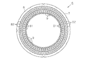
上記のように第1系統3相巻線と第2系統3相巻線が巻回されたステータ6の内側には、図1に示すように、ロータ11が配設されている。ロータ11は回転軸12を有し、該回転軸12は筒状ハウジング3のリアカバー壁3a及びフロントカバー4に設けられた軸受け14,15により回転可能に支持されている。又、ロータ11の回転軸12にはロータコア16が外嵌され、該ロータコア16の外周には、前記ステータ6、詳しくはティース9の径方向内側端部と相対向するように複数のマグネットMGが等角度間隔で設けられている。尚、本実施形態のロータ11は、図18に示すように、コンシクエントポール型のロータコアであって、そのロータコア16に取着されたマグネットMGの数は5個、突極17の数は5個で界磁極数は10個となっている。
As shown in FIG. 1, the
ちなみに、コンシクエントポール型のロータのモータにおいては、図19に示すように、2×p極(但し、「p」は極対数)の磁極が周方向に配置されたコンシクエントロータ11と、前記磁極当たり複数個設けられる前記ロータ11と径方向に対向して、ティース9(スロットS)の個数「Z」が、「2×p×m×n(個)」(但し、「m」はステータ巻線の相数、「n」は自然数)を有するコア7と前記スロットSに巻回された多相の巻線を有するステータ6とからなる。
By the way, in the motor of the continuous pole type rotor, as shown in FIG. 19, the
ちなみに、図19に示す場合では、この数式に基づいて、ティース9の個数「Z」は、
Z=2×5(マグネットMGの個数)×3(相数)×2=60個
となる。
Incidentally, in the case shown in FIG. 19, the number “Z” of
Z = 2 × 5 (number of magnets MG) × 3 (number of phases) × 2 = 60.
また、コンシクエントロータ11のロータコア16は、鋼板よりなるロータコア片が積層されて形成されている。また、ロータコア16には、径方向位置に、ロータコア片よりも比重及び磁性の小さい空隙30(小磁性軽量部)が形成されている。
The
これにより、磁気がロータコア16内で移動し易いコンシクエントロータ11においては、空隙30(小磁性軽量部)の磁気移動抑制効果による渦電流抑制効果に加えて、ロータコア片が複数積層されることで、さらに渦電流の発生が抑制される。
Thereby, in the
また、筒状ハウジング3のリアカバー壁3aの内側であって、ステータ6に配線した第1系統3相巻線の中性線L1nと対峙した位置に、第1収容凹部18を形成し、その第1収容凹部18に、中性線L1nが介在するスペースを設けている。これによって、リアカバー壁3a側に張り出される中性線L1を、この第1収容凹部18により軸方向に逃がすことができ、その分、モータの軸方向の体格を小さくできる。
A
この第1収容凹部18には、第1貫通孔H1が形成されている。第1収容凹部18に形成された第1貫通孔H1は、長孔であって、中性線L1nに隣接して形成された第1系統3相巻線の各相の電力受電端子T1u,T1v,T1wと対峙している。そして、電力受電端子T1u,T1v,T1wから引き出される各引出線L1u,L1v,L1wが、図1に示すように、第1貫通孔H1を貫通して収容ボックス5内に案内されるようになっている。
A first through hole H <b> 1 is formed in the
また、筒状ハウジング3のリアカバー壁3aの内側であって、ステータ6に配線した第2系統3相巻線の中性線L2nと対峙した位置に、第2収容凹部19を形成し、その第2収容凹部19に、中性線L2nが介在するスペースを設けている。これによって、リアカバー壁3a側に張り出される中性線L2を、この第2収容凹部19により軸方向に逃がすことができ、その分、モータの軸方向の体格を小さくできる。
A
この第2収容凹部19には、第2貫通孔H2が形成されている。第2収容凹部19に形成された第2貫通孔H2は、長孔であって、中性線L2nに隣接して形成された第2系統3相巻線の各相の電力受電端子T2u,T2v,T2wと対峙している。そして、電力受電端子T2u,T2v,T2wから引き出される各引出線L2u,L2v,L2wが、図1に示すように、第2貫通孔H2を貫通して収容ボックス5内に案内されるようになっている。
A second through hole H2 is formed in the
リアカバー壁3aの外側に固設した収容ボックス5内には、駆動装置20が収納されている。駆動装置20の回路基板21は、ロータ11の回転制御するための回転センサ22、ECU(電子制御ユニット)23、第1スイッチングトランジスタQ1u,Q1v,Q1w及び第2スイッチングトランジスタQ2u,Q2v,Q2w等の各種の回路素子が実装されている。
A
回転センサ22は、リアカバー壁3aから外側に軸線方向に突出した回転軸12に相対向するように回路基板21に実装されている。回転センサ22は、本実施形態ではホールICからなり、回転軸12の軸端面に固着した回転センサ22と一体回転する検出用マグネット22aの回転角を検出する。
The
ECU(電子制御ユニット)23は、マイクロコンピュータを有している。ECU23は、回転センサ22からの検出信号に基づいて、その時々のブラシレスモータ1の回転角度、回転速度等を検出する。そして、ECU23は、第1系統3相巻線及び第2系統3相巻線の各相へ電力供給タイミング演算する。
The ECU (electronic control unit) 23 has a microcomputer. Based on the detection signal from the
第1スイッチングトランジスタQ1u,Q1v,Q1wは、例えば、パワーMOSトランジスタからなり、ECU23の制御信号に基づいて、オンオフ制御されるようになっている。第1スイッチングトランジスタQ1u,Q1v,Q1wは、所定のタイミングでオンオフ制御されることによって、第1系統3相巻線の各相に電力をそれぞれ供給制御する。これによって、第1系統3相巻線による回転磁界がステータ6に生成される。
The first switching transistors Q1u, Q1v, and Q1w are, for example, power MOS transistors, and are on / off controlled based on a control signal from the
回路基板21に実装された第1スイッチングトランジスタQ1u,Q1v,Q1wは、軸線方向から見て、第1系統3相巻線に形成した各相の電力受電端子T1u,T1v,T1wと相対向する側に実装されている。そして、その回路基板21の第1スイッチングトランジスタQ1u,Q1v,Q1wとそれぞれ接続され、軸線方向から見て電力受電端子T1u,T1v,T1wと相対向する前記回路基板21の径方向外周側の位置には、各相に電力を供給する出力端子O1u,O1v,O1wがそれぞれ形成されている。
The first switching transistors Q1u, Q1v, and Q1w mounted on the
従って、各相の電力受電端子T1u,T1v,T1wから引き出される各引出線L1u,L1v,L1wは、リアカバー壁3aに形成した第1貫通孔H1を貫通して各相の電力受電端子T1u,T1v,T1wと各相に出力端子O1u,O1v,O1wとを軸線方向に最短距離でそれぞれ接続する。 Accordingly, the lead lines L1u, L1v, L1w led out from the power receiving terminals T1u, T1v, T1w of each phase pass through the first through holes H1 formed in the rear cover wall 3a, and the power receiving terminals T1u, T1v of each phase. , T1w and the output terminals O1u, O1v, O1w are connected to the respective phases with the shortest distance in the axial direction.
第2スイッチングトランジスタQ2u,Q2v,Q2wは、例えば、パワーMOSトランジスタからなり、ECU23の制御信号に基づいて、オンオフ制御されるようになっている。第2スイッチングトランジスタQ2u,Q2v,Q2wは、所定のタイミングでオンオフ制御されることによって、第2系統3相巻線の各相に電力をそれぞれ供給制御する。これによって、第2系統3相巻線による回転磁界がステータ6に生成される。
The second switching transistors Q2u, Q2v, Q2w are made of, for example, power MOS transistors, and are on / off controlled based on a control signal from the
回路基板21に実装された第2スイッチングトランジスタQ2u,Q2v,Q2wは、軸線方向から見て、第2系統3相巻線に形成した各相の電力受電端子T2u,T2v,T2wと相対向する側に実装されている。そして、その回路基板21の第1スイッチングトランジスタQ1u,Q1v,Q1wとそれぞれ接続され、軸線方向から見て電力受電端子T2u,T2v,T2wと相対向する位置には、各相に電力を供給する出力端子O2u,O2v,O2wがそれぞれ形成されている。
The second switching transistors Q2u, Q2v, and Q2w mounted on the
従って、各相の電力受電端子T2u,T2v,T2wから引き出される各引出線L2u,L2v,L2wは、リアカバー壁3aに形成した第2貫通孔H2を貫通して各相の電力受電端子T2u,T2v,T2wと各相に出力端子O2u,O2v,O2wとを軸線方向に最短距離でそれぞれ接続する。 Accordingly, the lead lines L2u, L2v, and L2w led out from the power receiving terminals T2u, T2v, and T2w of each phase pass through the second through hole H2 formed in the rear cover wall 3a, and the power receiving terminals T2u, T2v of each phase. , T2w and each phase are connected to the output terminals O2u, O2v, O2w at the shortest distance in the axial direction.
なお、本実施形態のブラシレスモータ1は、電動パワーステアリング装置等に用いられるものであって、前記ロータ11の回転軸12が、図示しない減速機に連結され、該減速機を介して被駆動部としての図示しないステアリングシャフト等の相手シャフトに連結され、同ステアリングシャフト等の相手シャフトを駆動するものである。
The
次に、上記実施の形態の特徴的な作用効果を以下に記載する。
(1)本実施形態によれば、ステータ6のSC巻線の各電力受電端子T1u,T1v,T1w,T2u,T2v,T2wを、フロントカバー4側に設けたセグメントSGの先端部間の溶接部材B1,B2と反対側のリアカバー壁3a側に設けた。従って、各電力受電端子T1u,T1v,T1w,T2u,T2v,T2wは、フロントカバー4側の密集する溶接箇所を避けて、リアカバー壁3a側でそれぞれ各引出線L1u,L1v,L1w,L2u,L2v,L2wと接続でき、コギングトルクの小さなSC巻線からなるブラシレスモータ1の体格を小さくできる。
Next, characteristic effects of the above embodiment will be described below.
(1) According to the present embodiment, each power receiving terminal T1u, T1v, T1w, T2u, T2v, T2w of the SC winding of the
また、各電力受電端子T1u,T1v,T1w,T2u,T2v,T2wを、セグメントSGの先端間の溶接部分ではなく、リアカバー壁3a側に配置された寸法形成されたU字状のセグメントSGの連結導体部ISc,OScに形成したので、SC巻線を形成する各U字状のセグメントSGの連結導体部ISc,OScとリアカバー壁3aと間のクリアランスを短くでき、ブラシレスモータ1の体格を小さくできる。
In addition, each power receiving terminal T1u, T1v, T1w, T2u, T2v, T2w is connected not to the welded portion between the ends of the segment SG but to a U-shaped segment SG having a dimension formed on the rear cover wall 3a side. Since the conductor portions ISc and OSc are formed, the clearance between the connecting conductor portions ISc and OSc of each U-shaped segment SG forming the SC winding and the rear cover wall 3a can be shortened, and the size of the
また、各電力受電端子T1u,T1v,T1w,T2u,T2v,T2wに接続された対応する各引出線L1u,L1v,L1w,L2u,L2v,L2wは、寸法形成されたセグメントSGの連結導体部ISc,OScからそのまま軸方向に引き出してくるので、収容ボックス5内の回路基板21に設けた各出力端子O1u,O1v,O1w,O2u,O2v,O2wとの接続が容易となる。
Also, the corresponding lead lines L1u, L1v, L1w, L2u, L2v, and L2w connected to the power receiving terminals T1u, T1v, T1w, T2u, T2v, and T2w are connected conductor portions ISc of the segment SG that is dimensionally formed. , OSc is pulled out in the axial direction as it is, and it becomes easy to connect the output terminals O1u, O1v, O1w, O2u, O2v, O2w provided on the
リアカバー壁3a側に設けた各電力受電端子T1u,T1v,T1w,T2u,T2v,T2wは、軸線方向に引き出されリアカバー壁3aに形成した第1及び第2貫通孔H1,H2を、それぞれ各引出線L1u,L1v,L1w,L2u,L2v,L2wを介して、貫通してリアカバー壁3aに隣接する制御回路の各出力端子O1u,O1v,O1w,O2u,O2v,O2wに接続されるようにしたので、制御回路の部品をその内径側に置くことが可能になり、制御回路を有するブラシレスモータ1の体格が全体として小体格となる。
The power receiving terminals T1u, T1v, T1w, T2u, T2v, and T2w provided on the rear cover wall 3a side are drawn out in the axial direction to the first and second through holes H1 and H2 formed in the rear cover wall 3a, respectively. Because it is connected to the output terminals O1u, O1v, O1w, O2u, O2v, and O2w of the control circuit that passes through the lines L1u, L1v, L1w, L2u, L2v, and L2w and is adjacent to the rear cover wall 3a. The parts of the control circuit can be placed on the inner diameter side, and the physique of the
また、セグメントSGの溶接部分をフロントカバー4側、すなわち、制御回路と反対側にしたので、溶接時の残渣が収容ボックス5内の制御回路の各回路等に付着することも抑制することができる。
Moreover, since the welding part of segment SG was made into the
(2)本実施形態によれば、リアカバー壁3a側に設けた各電力受電端子T1u,T1v,T1w,T2u,T2v,T2wは、スロットS内の径方向において3番目に外側の位置にそれぞれ配置されることから、軸線方向に引き出される各引出線L1u,L1v,L1w,L2u,L2v,L2wは、収容ボックス5内の制御回路の部品を実装する回路基板21に外側に対峙する。そのため、回路基板21の外側に各出力端子O1u,O1v,O1w,O2u,O2v,O2wを配置し、回路基板21の内側に回路部品を実装することが可能になり、制御回路を有するブラシレスモータ1の体格を全体として小さくできる。
(2) According to the present embodiment, the power receiving terminals T1u, T1v, T1w, T2u, T2v, and T2w provided on the rear cover wall 3a side are respectively arranged at the third outer positions in the radial direction in the slot S. Therefore, each of the lead lines L1u, L1v, L1w, L2u, L2v, and L2w drawn in the axial direction is opposed to the
(3)本実施形態によれば、フロントカバー4側に配置されたステータ6の周方向に繋げたセグメントSGの先端部間の各溶接部材B1,B2は、軸方向の長さが同一になるようにした。従って、SC巻線を形成する各セグメントSGの先端部間の各溶接部材B1,B2とフロントカバー4と間のクリアランスを短くでき、ブラシレスモータ1の軸方向の体格を小さくできる。
(3) According to the present embodiment, the welding members B1 and B2 between the tips of the segments SG connected in the circumferential direction of the
加えて、セグメントSGの溶接部の高さが同一なので、溶接する際の軸方向移動が不要となるため、溶接を短時間で実施できる。
(4)本実施形態によれば、筒状ハウジング3のリアカバー壁3aの内側であって、中性線L1n,L2nと対峙した位置に、第1及び第2収容凹部18,19を形成し、その第1及び第2第1収容凹部18,19に、中性線L1n,L2nが介在するスペースを設けた。これによって、リアカバー壁3a側に張り出される中性線L1,L2nを、この第1及び第2収容凹部18,19により軸方向に吸収することができ、その分、モータの軸方向の体格を小さくできる。
In addition, since the height of the welded portion of the segment SG is the same, the axial movement at the time of welding becomes unnecessary, so that welding can be performed in a short time.
(4) According to this embodiment, the first and
(5)本実施形態によれば、第1及び第2収容凹部18,19であって中性線L1n,L2nに隣接して形成された第1及び第2系統3相巻線の電力受電端子T1u,T1v,T1w,T2u,T2v,T2wと対峙した部分に、それぞれ第1及び第2貫通孔H1,H2を形成した。従って、第1及び第2貫通孔H1は、それぞれ引出線L1u,L1v,L1w,L2u,L2v,L2wを貫通させるだけの最低限の大きさの孔にすることができ、モータケース2と収容ボックス5との間で、行き来する異物の相互間移動を抑制することができる。
(5) According to the present embodiment, the power receiving terminals of the first and second system three-phase windings formed adjacent to the neutral wires L1n and L2n in the first and
上記実施の形態は、以下のように変更してもよい。
・上記実施の形態では、第1及び第2収容凹部18,19の一部分の電力受電端子T1u,T1v,T1w,T2u,T2v,T2wと対峙した部分に、それぞれ第1及び第2貫通孔H1,H2を形成した。これを、リアカバー壁3aに第1及び第2収容凹部18,19を形成しない実施してもよい。
The above embodiment may be modified as follows.
In the above-described embodiment, the first and second through holes H1, respectively, are provided in the portions facing the power receiving terminals T1u, T1v, T1w, T2u, T2v, T2w in a part of the first and second receiving recesses 18, 19. H2 was formed. You may implement this without forming the 1st and 2nd accommodating recessed
この場合、図20に示すように、第2系統3相巻線の各引出線L2u,L2v,L2wを貫通するリアカバー壁3aに形成した第1及び第2貫通孔H1,H2の径方向の幅を、中性線L1n,L2nが軸方向から見て視認できるように、中心軸線側に幅を持たして形成する。この場合、リアカバー壁3a側に張り出される中性線L1,L2nは、この第1及び第2貫通孔H1,H2により軸方向に逃がすことができ、その分、モータの軸方向の体格を小さくできる。 In this case, as shown in FIG. 20, the width in the radial direction of the first and second through holes H1, H2 formed in the rear cover wall 3a that penetrates the lead lines L2u, L2v, L2w of the second system three-phase winding. Is formed with a width on the central axis side so that the neutral lines L1n and L2n can be seen from the axial direction. In this case, the neutral lines L1 and L2n projecting toward the rear cover wall 3a can be released in the axial direction by the first and second through holes H1 and H2, and accordingly, the size of the motor in the axial direction is reduced. it can.
・上記実施の形態では、モータケース2は、有底の筒状ハウジング3とフロントカバー4とで形成した。これを、筒状ハウジング3をリア側及びフロント側の両側が開口した筒状ハウジングとし、その筒状ハウジング3のフロント側開口部をフロントカバー4で閉塞し、筒状ハウジング3のリア側開口部をリアカバーで閉塞してモータケース2を形成してもよい。この場合、リアカバーにリアカバー壁3aに代わって、第1及び第2収容凹部18,19や第1及び第2貫通孔H1,H2が形成されることになる。
In the above embodiment, the
・上記実施の形態では、外側導体OSの連結導体部OScの分離端であって同外側導体OSの第1導体部OSiに繋がる方を中性点端子とし、内側導体ISの連結導体部IScの分離端であって同内側導体ISの第3導体部ISoに繋がる方を電力受電端子とした。 In the above embodiment, the separation end of the connecting conductor portion OSc of the outer conductor OS and the one connected to the first conductor portion OSi of the outer conductor OS is used as the neutral point terminal, and the connecting conductor portion ISc of the inner conductor IS is connected. The one connected to the third conductor portion ISo of the inner conductor IS at the separation end was defined as a power receiving terminal.
これを、例えば、外側導体OSの連結導体部OScの分離端であって同外側導体OSの第1導体部OSiに繋がる方を電力受電端子とし、内側導体ISの連結導体部IScの分離端であって同内側導体ISの第3導体部ISoに繋がる方を中性点端子として実施してもよい。この場合、各相の電力受電端子は、各相の中性点端子よりスロットS内の径方向において内側に配置される。そのため、回路基板21に形成される各相に出力端子O1u,O1v,O1w,O2u,O2v,O2wが、配線レイアウトの制約から回路基板21の中央部周辺に形成される場合、引出線L1u,L1v,L1w,L2u,L2v,L2wを外側に配置される中性線L1n,L2nをクロスすることなく最も短くすることができる。
For example, a power receiving terminal is a separation end of the connection conductor portion OSc of the outer conductor OS and is connected to the first conductor portion OSi of the outer conductor OS, and a separation end of the connection conductor portion ISc of the inner conductor IS. In this case, the neutral conductor terminal may be used to connect to the third conductor portion ISo of the inner conductor IS. In this case, the power receiving terminal of each phase is arranged inside in the radial direction in the slot S from the neutral point terminal of each phase. Therefore, when the output terminals O1u, O1v, O1w, O2u, O2v, and O2w are formed around the center of the
・上記実施の形態では、上記実施形態ではスロットSの数を60個にしたが、これに限定されるものではなく、例えば、スロットSの数を45個にする等、適宜変更して実施してもよい。 In the above embodiment, the number of slots S is 60 in the above embodiment, but the present invention is not limited to this. For example, the number of slots S may be changed to 45, etc. May be.
・上記実施の形態では、引出線の配線長さを最短とするために、第1系統3相Y結線巻線の各相の電力受電端子T1u,T1v,T1wを、周方向にW1相、V1相、U1相の順で配置し、第2系統3相Y結線巻線の各相の電力受電端子T2u,T2v,T2wを、周方向にU2相、W2相、V2相の順で配置した。 In the embodiment described above, in order to minimize the wiring length of the leader line, the power receiving terminals T1u, T1v, T1w of each phase of the first system three-phase Y-connection winding are connected to the W1 phase, V1 in the circumferential direction. The power receiving terminals T2u, T2v, and T2w of each phase of the second system three-phase Y-connection winding are arranged in the order of the U2, W2, and V2 phases in the circumferential direction.
これを、第1系統3相Y結線巻線の各相の電力受電端子T1u,T1v,T1wに合わせて、第2系統3相Y結線巻線の各相の電力受電端子T2u,T2v,T2wを、周方向にW2相、V2相、U2相の順で配置して実施してもよい。 Matching this with the power receiving terminals T1u, T1v, T1w of each phase of the first system three-phase Y connection winding, the power receiving terminals T2u, T2v, T2w of each phase of the second system three phase Y connection winding are set. In the circumferential direction, W2 phase, V2 phase, and U2 phase may be arranged in this order.
この場合、図7において、第2系統3相Y結線巻線のW2相の電力受電端子T2w及び中性点端子T0waは、スロット番号「23」及び「29」のスロットSに挿入されるセグメントSGにて形成される。つまり、スロット番号「23」及び「29」のスロットSに挿入されるセグメントSGについて、波巻用の外側導体OSの連結導体部OSc及び前記重ね巻用の内側導体ISの連結導体部IScをそれぞれ分離する。そして、そして、上記同様に接続した後、内側導体ISの第3導体部ISoに繋がる分離端をW2相の電力受電端子T2wとするとともに、外側導体OSの第1導体部OSiに繋がる分離端をW2相の中性点端子T0waとする。 In this case, in FIG. 7, the W2-phase power receiving terminal T2w and the neutral point terminal T0wa of the second system three-phase Y-connection winding are the segments SG inserted into the slots S of the slot numbers “23” and “29”. Is formed. That is, for the segment SG inserted in the slot S with slot numbers “23” and “29”, the connecting conductor part OSc of the outer conductor OS for wave winding and the connecting conductor part ISc of the inner conductor IS for lap winding are respectively set. To separate. And after connecting in the same manner as described above, the separation end connected to the third conductor portion ISo of the inner conductor IS is a W2 phase power receiving terminal T2w, and the separation end connected to the first conductor portion OSi of the outer conductor OS is The neutral point terminal T0wa of the W2 phase is used.
また、W2相の電力受電端子T2v及び中性点端子T0vaは、スロット番号「27」及び「33」のスロットSに挿入されるセグメントSGにて形成される。つまり、スロット番号「27」及び「33」のスロットSに挿入されるセグメントSGについて、波巻用の外側導体OSの連結導体部OSc及び前記重ね巻用の内側導体ISの連結導体部IScをそれぞれ分離する。そして、上記同様に接続した後、内側導体ISの第3導体部ISoに繋がる分離端をV2相の電力受電端子T2vとするとともに、外側導体OSの第1導体部OSiに繋がる分離端をW2相の中性点端子T0vaとする。 Further, the W2 phase power receiving terminal T2v and the neutral point terminal T0va are formed by the segments SG inserted in the slots S having the slot numbers “27” and “33”. That is, for the segment SG inserted in the slot S with slot numbers “27” and “33”, the connecting conductor portion OSc of the wave winding outer conductor OS and the connecting conductor portion ISc of the inner conductor IS for lap winding are respectively set. To separate. After the connection in the same manner as described above, the separation end connected to the third conductor portion ISo of the inner conductor IS is the V2 phase power receiving terminal T2v, and the separation end connected to the first conductor portion OSi of the outer conductor OS is the W2 phase. The neutral point terminal T0va.
さらに、U2相の電力受電端子T2u及び中性点端子T0uaは、スロット番号「31」及び「37」のスロットSに挿入されるセグメントSGにて形成される。つまり、スロット番号「31」及び「37」のスロットSに挿入されるセグメントSGについて、波巻用の外側導体OSの連結導体部OSc及び前記重ね巻用の内側導体ISの連結導体部IScをそれぞれ分離する。そして、上記同様に接続した後、内側導体ISの第3導体部ISoに繋がる分離端をU2相の電力受電端子T2uとするとともに、外側導体OSの第1導体部OSiに繋がる分離端をU2相の中性点端子T0uaとする。 Further, the U2-phase power receiving terminal T2u and the neutral point terminal T0ua are formed by the segment SG inserted in the slot S having the slot numbers “31” and “37”. That is, for the segment SG inserted into the slot S with slot numbers “31” and “37”, the connecting conductor part OSc of the outer conductor OS for wave winding and the connecting conductor part ISc of the inner conductor IS for lap winding are respectively set. To separate. Then, after connecting in the same manner as described above, the separation end connected to the third conductor portion ISo of the inner conductor IS is the U2 phase power receiving terminal T2u, and the separation end connected to the first conductor portion OSi of the outer conductor OS is the U2 phase. Let the neutral point terminal T0ua be.
この場合でも、各相の電力受電端子T2u,T2v,T2wを、径方向において中性点端子T0ua,T0va,T0waより外側に配置できる。
・上記実施の形態では、電力受電端子及び前記中性点端子を前記波巻用の外側導体OSの連結導体部OSc及び前記重ね巻用の内側導体ISの連結導体部IScでそれぞれ分離し、その一方を前記外側導体OSの前記第4導体部OSoに繋がる分離端と前記内側導体ISの前記第2導体部ISiに繋がる分離端とを電気的に接続するとともに、その他方を用いず、前記内側導体ISの分離した他方のものと同形態であって前記第3導体部ISoに繋がって軸方向に延びる引出し部を一体に形成した第1片側セグメントを用い、その引出し部を各相の前記電力受電端子T1u,T1v,T1w,T2u,T2v,T2wとし、前記外側導体OSの分離した他方のもとの同形態であって前記第1導体部OSiに繋がって軸方向に延びる引出し部を一体に形成した第2片側セグメントを用い、その引出し部を各相の前記中性点端子T0u,T0v,T0w,T0ua,T0va,T0waとしてもよい。
Even in this case, the power receiving terminals T2u, T2v, T2w of each phase can be arranged outside the neutral point terminals T0ua, T0va, T0wa in the radial direction.
In the above embodiment, the power receiving terminal and the neutral point terminal are separated by the connecting conductor portion OSc of the outer conductor OS for wave winding and the connecting conductor portion ISc of the inner conductor IS for lap winding, respectively. One side is electrically connected to the separation end connected to the fourth conductor portion OSo of the outer conductor OS and the separation end connected to the second conductor portion ISi of the inner conductor IS, and the other side is used without using the other side. A first one-side segment having the same configuration as that of the other separated conductor IS and integrally formed with a lead portion extending in the axial direction connected to the third conductor portion ISo is used as the lead portion for the power of each phase. The power receiving terminals T1u, T1v, T1w, T2u, T2v, and T2w are the same form of the other separated outer conductor OS, and are connected to the first conductor portion OSi and extend in the axial direction. Using a second one segment formed body, the lead portions of each phase of the neutral point terminal T0u, T0v, T0w, T0ua, T0va, may be T0wa.
この場合、軸方向に延びる引出し部を一体に形成した第1片側セグメントにおいて、その引出し部を電力受電端子T1u,T1v,T1w,T2u,T2v,T2wとした場合には、電力受電端子T1u,T1v,T1w,T2u,T2v,T2wは引出線L1u,L1v,L1w,L2u,L2v,L2wとなる。 In this case, in the first one-side segment integrally formed with the extending portion extending in the axial direction, when the extracted portion is the power receiving terminals T1u, T1v, T1w, T2u, T2v, T2w, the power receiving terminals T1u, T1v. , T1w, T2u, T2v, and T2w become lead lines L1u, L1v, L1w, L2u, L2v, and L2w.
・上記実施の形態では、SC巻線について、前記波巻用の外側導体OSと前記重ね巻用の内側導体ISを周方向に交互に連結するものとしたが、波巻用の内側導体ISのみを周方向に連結するものであってもよいし、前記重ね巻用の外側導体OSのみを周方向に連結するものであってもよい。 In the above embodiment, for the SC winding, the wave winding outer conductor OS and the lap winding inner conductor IS are alternately connected in the circumferential direction, but only the wave winding inner conductor IS. May be connected in the circumferential direction, or only the outer conductor OS for lap winding may be connected in the circumferential direction.
・上記実施の形態では、各電力受電端子は、それぞれの引出線を介して対応する出力端子とそれぞれ接続した。これを、各電力受電端子をそのまま軸線方向に引出線として延ばして対応する出力端子とそれぞれ接続するようにしてもよい。 In the above embodiment, each power receiving terminal is connected to the corresponding output terminal via each lead wire. Alternatively, each power receiving terminal may be directly extended as a leader line in the axial direction and connected to a corresponding output terminal.
1…ブラシレスモータ(モータ)、2…モータケース、3…筒状ハウジング、3a…リアカバー壁(リアカバー)、4…フロントカバー、5…収容ボックス、6…ステータ、7…コア、8…円筒部、9…ティース、10…インシュレータ、11,30…ロータ、12…回転軸、14,15…軸受、16…ロータコア、17…突極、18…第1収容凹部、19…第2収容凹部、20…駆動装置、21…回路基板、22…回転センサ、22a…検出用マグネット、23…ECU(電子制御ユニット)、30…空隙、B1,B2…溶接部材、S…スロット、S1〜S4…先端面、H1…第1貫通孔、H2…第2貫通孔、IS…内側導体、MG…マグネット、N1,N2…中性点、OS…外側導体、SG…セグメント、ISc,OSc…連結導体部、ISi…第2導体部、ISo…第3導体部、IWi…第2溶接部、IWo…第3溶接部、L1n,L2n…中性線(結線部)、L1u,L1v,L1w,L2u,L2v,L2w…引出線、O1u,O1v,O1w,O2u,O2v,O2w…出力端子、OSi…第1導体部、OSo…第4導体部、OWi…第1溶接部、OWo…第4溶接部、Q1u,Q1v,Q1w…第1スイッチングトランジスタ、Q2u,Q2v,Q2w…第2スイッチングトランジスタ、SG1〜SG10,SG1a〜SG10a…セグメント、T0u,T0v,T0w,T0ua,T0va,T0wa…中性点端子、T1u,T1v,T1w,T2u,T2v,T2w…電力受電端子。
DESCRIPTION OF
Claims (8)
前記モータケース内に配設され、回転軸の中心軸線に向かって延出形成されたてティースが径方向に等間隔に複数個配置され、ティースとティース間に形成される軸線方向に延びる各スロットに、U字状のセグメントが一方向から挿入され、各スロットから突出した先端間を周方向に繋げてなるSC巻線にて形成されたステータと、
を備えたモータであって、
前記ステータを、周方向に繋げたU字状のセグメントの先端間の溶接部がフロントカバーに、SC巻線の電力受電端子がリアカバーにそれぞれ対峙するように、モータケースに配設し、
前記SC巻線の電力受電端子をそのまま引出線としあるいは引出線を接続し、その引出線を軸方向に延出させてリアカバーに形成した貫通孔から突出させて前記リアカバーに隣接する制御回路の端子と接続するようにしたことを特徴とするモータ。 A motor case in which a front cover is attached to the front side opening of the cylindrical case and a rear cover is attached to the rear side opening of the cylindrical case;
Each slot disposed in the motor case and extending toward the central axis of the rotating shaft is provided with a plurality of teeth arranged at equal intervals in the radial direction, and extends in the axial direction between the teeth. A U-shaped segment is inserted from one direction, and a stator formed by an SC winding formed by connecting ends protruding from the slots in the circumferential direction;
A motor equipped with
The stator is disposed in the motor case so that the welded portion between the ends of the U-shaped segments connected in the circumferential direction faces the front cover, and the power receiving terminal of the SC winding faces the rear cover.
The power receiving terminal of the SC winding is directly used as a leader line or connected to a leader line, and the leader line is extended in the axial direction so as to protrude from a through hole formed in the rear cover and adjacent to the rear cover. A motor characterized by being connected to.
前記電力受電端子は、スロットS内の径方向において外側の位置にそれぞれ配置され、その電力受電端子に接続された前記引出線が軸線方向にリアカバーに形成した貫通孔を介して前記制御回路の端子と接続したことを特徴とするモータ。 The motor according to claim 1,
The power receiving terminals are respectively arranged at positions outside in the radial direction in the slot S, and the lead wires connected to the power receiving terminals are connected to the terminals of the control circuit via through holes formed in the rear cover in the axial direction. A motor characterized by being connected to.
前記フロントカバー側に配置された前記ステータの周方向に繋げたU字状のセグメントの先端間の各溶接部は、軸方向の長さが同一であることを特徴とするモータ。 The motor according to claim 1 or 2,
Each of the welds between the tips of U-shaped segments connected in the circumferential direction of the stator disposed on the front cover side has the same axial length.
前記ステータに巻装したSC巻線は、各相の中性点端子を互いに接続する中性線を、リアカバーと対峙する位置に形成し、前記リアカバーには前記中性線あるいは中性線と前記中性点端子との結線部を逃がす収容凹部が形成されていることを特徴とするモータ。 The motor according to any one of claims 1 to 3,
The SC winding wound around the stator is formed with a neutral wire connecting the neutral point terminals of each phase at a position facing the rear cover, and the rear cover includes the neutral wire or the neutral wire and the neutral wire. A motor, wherein an accommodation recess for escaping a connection portion with a neutral point terminal is formed.
前リアカバーに形成した収容凹部は、前記引出線を貫通させる前記貫通孔であることを特徴とするモータ。 The motor according to claim 4,
An accommodation recess formed in the front rear cover is the through hole through which the lead wire passes.
前記SC巻線は、第1導体部と第4導体部を有し前記第1導体部と前記第4導体部が基端部で連結された波巻用の外側導体と、第2導体部と第3導体部を有し前記第2導体部と前記第3導体部が基端部で連結され前記波巻用の外側導体に内包される重ね巻用の内側導体とからなるセグメントを有し、前記第1導体部と前記第2導体部、及び、前記第3導体部と前記第4導体部をそれぞれの組とし、前記各組を互いに隣接する同相の各スロットにそれぞれ挿入し、前記各スロットに、前記第1導体部から第4導体部を径方向に内側から第1導体部、第2導体部、第3導体部、第4導体部の順で配置し、
隣接する一方のスロットの第1導体部の先端部と隣接する他方のスロットの第2導体部の先端部とを接続するとともに、隣接する一方のスロットの第3導体部の先端部と隣接する他方のスロットの第4導体部の先端部とを接続することによって、SC巻線よりなる3相Y結線巻線が2つ1スロットピッチずれて形成され、前記2つの3相Y結線巻線の各相の電力受電端子と中性点端子を、それぞれ同一の導体部から軸線方向に引き出したことを特徴とするモータ。 The motor according to any one of claims 1 to 5,
The SC winding includes a first conductor portion and a fourth conductor portion, and an outer conductor for wave winding in which the first conductor portion and the fourth conductor portion are connected at a base end portion, a second conductor portion, Having a third conductor portion, the second conductor portion and the third conductor portion being connected at the base end portion, and having a segment composed of an inner conductor for lap winding enclosed in the outer conductor for wave winding, The first conductor portion and the second conductor portion, and the third conductor portion and the fourth conductor portion are each set, and each set is inserted into each slot of the same phase adjacent to each other, and each slot The first conductor portion to the fourth conductor portion are arranged in the order of the first conductor portion, the second conductor portion, the third conductor portion, and the fourth conductor portion from the inside in the radial direction,
The other end adjacent to the tip end of the third conductor portion of one adjacent slot is connected to the tip end portion of the first conductor portion of one adjacent slot and the tip end portion of the second conductor portion of the other adjacent slot. By connecting the tip of the fourth conductor portion of the slot, three-phase Y-connection windings composed of SC windings are formed so as to be shifted by one slot pitch, and each of the two three-phase Y-connection windings is formed. A motor characterized in that a phase power receiving terminal and a neutral point terminal are each pulled out in the axial direction from the same conductor portion.
前記一方の3相Y結線巻線の各相の前記電力受電端子及び前記中性点端子は、
隣接する各相のセグメントについて、前記波巻用の外側導体の基端連結部分及び前記重ね巻用の内側導体の基端連結部分でそれぞれ分離し、その一方を前記外側導体の前記第4導体部に繋がる分離端と前記内側導体の前記第2導体部に繋がる分離端とを電気的に接続するとともに、その他方を用いず、前記内側導体の分離した他方のものと同形態であって前記第3導体部に繋がって軸方向に延びる引出し部を一体に形成した第1片側セグメントを用い、その引出し部を各相の前記電力受電端子とし、前記外側導体の分離した他方のもとの同形態であって前記第1導体部に繋がって軸方向に延びる引出し部を一体に形成した第2片側セグメントを用い、その引出し部を各相の前記中性点端子とし、
前記他方の3相Y結線巻線の各相の前記電力受電端子及び前記中性点端子は、
隣接する各相のセグメントについて、前記波巻用の外側導体の基端連結部分及び前記重ね巻用の内側導体の基端連結部分でそれぞれ分離し、その一方を前記外側導体の前記第4導体部に繋がる分離端と前記内側導体の前記第2導体部に繋がる分離端とを電気的に接続するとともに、その他方を用いず、前記内側導体の分離した他方のものと同形態であって前記第3導体部に繋がって軸方向に延びる引出し部を一体に形成した第1片側セグメントを用い、その引出し部を各相の前記電力受電端子とし、前記外側導体の分離した他方のもとの同形態であって前記第1導体部に繋がって軸方向に延びる引出し部を一体に形成した第2片側セグメントを用い、その引出し部を各相の前記中性点端子としたことを特徴とするモータ。 The motor according to claim 6, wherein
The power receiving terminal and the neutral point terminal of each phase of the one three-phase Y-connection winding are:
The adjacent phase segments are separated at the base end connecting portion of the outer conductor for wave winding and the base end connecting portion of the inner conductor for lap winding, one of which is the fourth conductor portion of the outer conductor. And the separation end connected to the second conductor portion of the inner conductor is electrically connected, and the other end is used, and the same configuration as that of the other separated inner conductor is used. Using the first one-side segment integrally formed with the lead portion extending in the axial direction and connected to the three conductor portions, the lead portion serves as the power receiving terminal of each phase, and the same form of the other separated outer conductor Then, using a second one-side segment integrally formed with the lead portion extending in the axial direction connected to the first conductor portion, the lead portion as the neutral point terminal of each phase,
The power receiving terminal and the neutral point terminal of each phase of the other three-phase Y-connection winding are:
The adjacent phase segments are separated at the base end connecting portion of the outer conductor for wave winding and the base end connecting portion of the inner conductor for lap winding, one of which is the fourth conductor portion of the outer conductor. And the separation end connected to the second conductor portion of the inner conductor is electrically connected, and the other end is used, and the same configuration as that of the other separated inner conductor is used. Using the first one-side segment integrally formed with the lead portion extending in the axial direction and connected to the three conductor portions, the lead portion serves as the power receiving terminal of each phase, and the same form of the other separated outer conductor The motor is characterized in that a second one-side segment integrally formed with an extraction portion extending in the axial direction and connected to the first conductor portion is used as the neutral point terminal of each phase.
前記磁極当たり複数個設けられる前記ロータと径方向に対向して2×p×m×n個(但し、mはステータ巻線の相数、nは自然数)のティース及びスロットを有するコアと前記スロットに巻回された多相の巻線とを有するステータと
を備えたブラシレスモータであって、
前記セグメントに定形状のセグメントが挿入されてステータ巻線を構成し、
前記セグメントの電力受電端子がそのまま軸線方向に延びる引出線となって、あるいは、軸線方向に延びる引出線に接続され、その引出線が前記ステータを内装する筒状ケースの開口部に配置されたカバーに形成された貫通孔から突出して前記カバーに隣接する制御回路の端子と接続するようにしたことを特徴とするモータ。 A continuous rotor in which magnetic poles of 2 × p poles (where p is the number of pole pairs) are alternately arranged in the circumferential direction;
A core having 2 × p × m × n (where m is the number of phases of the stator winding and n is a natural number) teeth and slots facing the rotor provided in a plurality in the radial direction, and the slots A brushless motor comprising a stator having a multiphase winding wound around
A fixed-shaped segment is inserted into the segment to constitute a stator winding,
The power receiving terminal of the segment is a lead wire extending in the axial direction as it is, or connected to a lead wire extending in the axial direction, and the lead wire is disposed at the opening of the cylindrical case that houses the stator A motor that protrudes from a through hole formed in the cover and is connected to a terminal of a control circuit adjacent to the cover.
Priority Applications (3)
| Application Number | Priority Date | Filing Date | Title |
|---|---|---|---|
| JP2011000178A JP2012143089A (en) | 2011-01-04 | 2011-01-04 | Motor |
| US13/335,000 US8916999B2 (en) | 2011-01-01 | 2011-12-22 | Motors containing segment conductor coils |
| CN201110462000.XA CN102593976B (en) | 2011-01-04 | 2011-12-29 | Motor |
Applications Claiming Priority (1)
| Application Number | Priority Date | Filing Date | Title |
|---|---|---|---|
| JP2011000178A JP2012143089A (en) | 2011-01-04 | 2011-01-04 | Motor |
Publications (1)
| Publication Number | Publication Date |
|---|---|
| JP2012143089A true JP2012143089A (en) | 2012-07-26 |
Family
ID=46678800
Family Applications (1)
| Application Number | Title | Priority Date | Filing Date |
|---|---|---|---|
| JP2011000178A Pending JP2012143089A (en) | 2011-01-01 | 2011-01-04 | Motor |
Country Status (1)
| Country | Link |
|---|---|
| JP (1) | JP2012143089A (en) |
Cited By (7)
| Publication number | Priority date | Publication date | Assignee | Title |
|---|---|---|---|---|
| JP2014064420A (en) * | 2012-09-24 | 2014-04-10 | Hitachi Industrial Equipment Systems Co Ltd | Dynamo-electric machine |
| JP2014107973A (en) * | 2012-11-28 | 2014-06-09 | Denso Corp | Rotary electric machine |
| JP2015201920A (en) * | 2014-04-04 | 2015-11-12 | アスモ株式会社 | motor |
| JP2016013000A (en) * | 2014-06-30 | 2016-01-21 | 日本精工株式会社 | Motor and electrically-driven power steering device mounting the same |
| JP2016101035A (en) * | 2014-11-25 | 2016-05-30 | 日本電産株式会社 | motor |
| JP2019176589A (en) * | 2018-03-28 | 2019-10-10 | 本田技研工業株式会社 | Wound coil, coil for rotary electric machine, rotary electric machine, and method and apparatus for manufacturing wound coil |
| EP3678282A1 (en) * | 2019-01-02 | 2020-07-08 | Lg Electronics Inc. | Stator of electric rotating machine, hairpin of stator of electric rotating machine and manufacturing method thereof |
Citations (6)
| Publication number | Priority date | Publication date | Assignee | Title |
|---|---|---|---|---|
| JP2002058189A (en) * | 2000-08-10 | 2002-02-22 | Mitsubishi Electric Corp | Rotating electric machine |
| JP2002078261A (en) * | 2000-08-25 | 2002-03-15 | Denso Corp | Ac generator for vehicle |
| JP2005269875A (en) * | 2004-03-22 | 2005-09-29 | Asmo Co Ltd | Motor |
| JP2007228756A (en) * | 2006-02-24 | 2007-09-06 | Denso Corp | Stator of ac generator for vehicle |
| JP2008211945A (en) * | 2007-02-28 | 2008-09-11 | Hitachi Ltd | Vehicle drive device |
| JP2010263763A (en) * | 2008-12-17 | 2010-11-18 | Asmo Co Ltd | Brushless motor |
-
2011
- 2011-01-04 JP JP2011000178A patent/JP2012143089A/en active Pending
Patent Citations (6)
| Publication number | Priority date | Publication date | Assignee | Title |
|---|---|---|---|---|
| JP2002058189A (en) * | 2000-08-10 | 2002-02-22 | Mitsubishi Electric Corp | Rotating electric machine |
| JP2002078261A (en) * | 2000-08-25 | 2002-03-15 | Denso Corp | Ac generator for vehicle |
| JP2005269875A (en) * | 2004-03-22 | 2005-09-29 | Asmo Co Ltd | Motor |
| JP2007228756A (en) * | 2006-02-24 | 2007-09-06 | Denso Corp | Stator of ac generator for vehicle |
| JP2008211945A (en) * | 2007-02-28 | 2008-09-11 | Hitachi Ltd | Vehicle drive device |
| JP2010263763A (en) * | 2008-12-17 | 2010-11-18 | Asmo Co Ltd | Brushless motor |
Cited By (10)
| Publication number | Priority date | Publication date | Assignee | Title |
|---|---|---|---|---|
| JP2014064420A (en) * | 2012-09-24 | 2014-04-10 | Hitachi Industrial Equipment Systems Co Ltd | Dynamo-electric machine |
| JP2014107973A (en) * | 2012-11-28 | 2014-06-09 | Denso Corp | Rotary electric machine |
| JP2015201920A (en) * | 2014-04-04 | 2015-11-12 | アスモ株式会社 | motor |
| JP2016013000A (en) * | 2014-06-30 | 2016-01-21 | 日本精工株式会社 | Motor and electrically-driven power steering device mounting the same |
| EP3163720A4 (en) * | 2014-06-30 | 2018-05-23 | NSK Ltd. | Motor, and electric power steering device and vehicle in which said motor is installed |
| US10218241B2 (en) | 2014-06-30 | 2019-02-26 | Nsk Ltd. | Motor, and electric power steering apparatus and vehicle equipped with the same |
| JP2016101035A (en) * | 2014-11-25 | 2016-05-30 | 日本電産株式会社 | motor |
| JP2019176589A (en) * | 2018-03-28 | 2019-10-10 | 本田技研工業株式会社 | Wound coil, coil for rotary electric machine, rotary electric machine, and method and apparatus for manufacturing wound coil |
| EP3678282A1 (en) * | 2019-01-02 | 2020-07-08 | Lg Electronics Inc. | Stator of electric rotating machine, hairpin of stator of electric rotating machine and manufacturing method thereof |
| US11557935B2 (en) | 2019-01-02 | 2023-01-17 | Lg Magna E-Powertrain Co., Ltd. | Stator of electric rotating machine, hairpin of stator of electric rotating machine and manufacturing method thereof |
Similar Documents
| Publication | Publication Date | Title |
|---|---|---|
| JP6068953B2 (en) | Electric motor | |
| JP5040303B2 (en) | Rotating electric machine | |
| JP2012157236A (en) | Brushless motor and brushless motor drive method | |
| JP5758718B2 (en) | Stator, motor, conductor manufacturing method, stator manufacturing method | |
| JP2012143089A (en) | Motor | |
| JP5070248B2 (en) | Rotating electric machine and manufacturing method thereof | |
| JP2018198482A (en) | Dynamoelectric machine | |
| EP3346586A1 (en) | Stator coil, stator equipped with same, and rotary electric machine equipped with this stator | |
| JP2008211880A (en) | Manufacturing method for rotating electrical machines and stators | |
| CN110771013B (en) | Stator of rotating electric machine and rotating electric machine | |
| CN109478814B (en) | Stator of rotating electric machine and rotating electric machine | |
| EP3352340A1 (en) | Stator coil, method for manufacturing stator, and dynamo-electric machine | |
| JPWO2013145977A1 (en) | Rotating electric machine | |
| CN110086280B (en) | Stator and rotating electric machine provided with same | |
| JP5700643B2 (en) | Brushless motor and driving method of brushless motor | |
| JP2019017211A (en) | Brushless motor and electric power steering system | |
| JP2012143087A (en) | Motor | |
| JP2014103834A (en) | Stator for rotary electric machine | |
| JPH08182236A (en) | Winding method of armature coil for electric rotating machine | |
| JP2021052536A (en) | Stator | |
| JP2012235671A (en) | Motor | |
| JP2013247715A (en) | Stator and motor | |
| CN110741537B (en) | Rotating electrical machine | |
| JP6926893B2 (en) | Rotating machine | |
| JP2014192997A (en) | Electric motor |
Legal Events
| Date | Code | Title | Description |
|---|---|---|---|
| A621 | Written request for application examination |
Free format text: JAPANESE INTERMEDIATE CODE: A621 Effective date: 20130925 |
|
| A131 | Notification of reasons for refusal |
Free format text: JAPANESE INTERMEDIATE CODE: A131 Effective date: 20140722 |
|
| A977 | Report on retrieval |
Free format text: JAPANESE INTERMEDIATE CODE: A971007 Effective date: 20140724 |
|
| A521 | Written amendment |
Free format text: JAPANESE INTERMEDIATE CODE: A523 Effective date: 20140903 |
|
| A131 | Notification of reasons for refusal |
Free format text: JAPANESE INTERMEDIATE CODE: A131 Effective date: 20150310 |
|
| A02 | Decision of refusal |
Free format text: JAPANESE INTERMEDIATE CODE: A02 Effective date: 20150701 |