JP2012142880A - Ultrasonic vibrator, ultrasonic probe and ultrasonic diagnostic apparatus - Google Patents
Ultrasonic vibrator, ultrasonic probe and ultrasonic diagnostic apparatus Download PDFInfo
- Publication number
- JP2012142880A JP2012142880A JP2011001036A JP2011001036A JP2012142880A JP 2012142880 A JP2012142880 A JP 2012142880A JP 2011001036 A JP2011001036 A JP 2011001036A JP 2011001036 A JP2011001036 A JP 2011001036A JP 2012142880 A JP2012142880 A JP 2012142880A
- Authority
- JP
- Japan
- Prior art keywords
- ultrasonic
- piezoelectric material
- layer
- ultrasonic probe
- pzt
- Prior art date
- Legal status (The legal status is an assumption and is not a legal conclusion. Google has not performed a legal analysis and makes no representation as to the accuracy of the status listed.)
- Pending
Links
Images


Abstract
Description
本発明は、被検体に超音波を送受信して超音波画像を取得するための超音波探触子およびこの超音波探触子を備えた超音波診断装置に関する。 The present invention relates to an ultrasonic probe for acquiring an ultrasonic image by transmitting / receiving ultrasonic waves to / from a subject and an ultrasonic diagnostic apparatus including the ultrasonic probe.
超音波は、通常、16000Hz以上の音波をいい、非破壊、無害及び略リアルタイムでその内部を調べることが可能なことから、欠陥の検査や疾患の診断等の様々な分野に応用されている。その一つに、被検体内を超音波で走査し、被検体内から来た超音波の反射波(エコー)から生成した受信信号に基づいて当該被検体内の内部状態を画像化する超音波診断装置がある。この超音波診断装置は、医療用では、他の医療用画像装置に較べて小型で安価であり、そしてX線等の放射線被爆が無く安全性が高いこと、また、ドップラ効果を応用した血流表示が可能であること等の様々な特長を有している。このため、超音波診断装置は、循環器系(例えば心臓の冠動脈等)、消化器系(例えば胃腸等)、内科系(例えば肝臓、膵臓及び脾臓等)、泌尿器系(例えば腎臓及び膀胱等)及び産婦人科系等で広く利用されている。 Ultrasound generally refers to sound waves of 16000 Hz or higher, and can be examined non-destructively, harmlessly and in substantially real time, and thus is applied to various fields such as defect inspection and disease diagnosis. For example, an ultrasound that scans the inside of the subject with ultrasound and images the internal state of the subject based on a reception signal generated from the reflected wave (echo) of the ultrasound coming from inside the subject. There is a diagnostic device. This ultrasonic diagnostic apparatus is smaller and less expensive for medical use than other medical imaging apparatuses, has no radiation exposure such as X-rays, is highly safe, and has a blood flow utilizing the Doppler effect. It has various features such as display capability. For this reason, an ultrasonic diagnostic apparatus includes a circulatory system (eg, coronary artery of the heart), a digestive system (eg, gastrointestinal), an internal system (eg, liver, pancreas, and spleen), and a urinary system (eg, kidney and bladder). Widely used in obstetrics and gynecology.
超音波診断装置には、被検体に対して超音波を送受信する超音波探触子が用いられている。超音波探触子は、圧電現象を利用することによって、送信の電気信号に基づいて機械振動して超音波を発生し、被検体内部で音響インピーダンスの不整合によって生じる超音波の反射波を受けて受信の電気信号を生成する複数の圧電素子(超音波振動子)を備え、これら複数の圧電素子が例えばアレイ状に配列されて構成されている。 An ultrasonic probe that transmits and receives ultrasonic waves to and from a subject is used in the ultrasonic diagnostic apparatus. An ultrasonic probe uses a piezoelectric phenomenon to generate an ultrasonic wave by mechanical vibration based on an electric signal transmitted, and receives an ultrasonic reflected wave caused by an acoustic impedance mismatch inside the subject. The plurality of piezoelectric elements (ultrasonic transducers) for generating received electrical signals are arranged, and the plurality of piezoelectric elements are arranged in an array, for example.
現在、配列方向は1次元方向のみに配列された超音波探触子が主流ではあるが、1次元配列では1平面内でしか超音波ビームを形成できないため、任意の方向にビームを形成することが可能となる2次元配列の超音波探触子が求められている。 Currently, ultrasonic probes arranged in only a one-dimensional direction are the mainstream, but an ultrasonic beam can be formed only in one plane with a one-dimensional array, so a beam is formed in an arbitrary direction. There is a need for a two-dimensional array of ultrasound probes that can be used.
一方、超音波探触子の周波数帯域は時間方向、すなわち距離分解能への要求から、より短い超音波パルスを形成可能な帯域の広いものが要求されている。 On the other hand, the frequency band of the ultrasonic probe is required to have a wide band in which a shorter ultrasonic pulse can be formed due to the demand in the time direction, that is, the distance resolution.
前述の複数の圧電素子を2Dマトリクスアレイ式に配列した超音波探触子を得るには、従来のアジマス方向のみならず,エレベーション方向にも超音波ビームを収束させる必要があるため、従来短冊形の直方体形状であった振動子をエレベーション方向で素子分割した小面積の振動子を形成する必要がある。 In order to obtain an ultrasonic probe in which the above-described plurality of piezoelectric elements are arranged in a 2D matrix array type, it is necessary to focus the ultrasonic beam not only in the conventional azimuth direction but also in the elevation direction. It is necessary to form a small-area vibrator by dividing a vibrator that has a rectangular parallelepiped shape into elements in the elevation direction.
ところが振動子面積を小面積とすると、振動子の静電容量が低下すると共にインピーダンスが増大し、伝送線路の浮遊容量やインピーダンス不整合等により充分なSN比で受信信号を得ることが出来なくなるという問題があった。 However, if the transducer area is small, the capacitance of the transducer decreases and the impedance increases, and it becomes impossible to obtain a received signal with a sufficient S / N ratio due to the stray capacitance of the transmission line and impedance mismatching. There was a problem.
この問題を解決するため、探触子の振動子近傍に信号増幅器を組み込む等の方法も行われているが、発熱等の新たな問題を生ずるため、従来の1次元アレイ式同様にこれらを用いることなく使用可能な2Dマトリクスアレイ式超音波探触子が望まれている。 In order to solve this problem, a method such as incorporating a signal amplifier near the transducer of the probe is also used. However, since these cause new problems such as heat generation, these are used in the same manner as the conventional one-dimensional array type. There is a demand for a 2D matrix array type ultrasonic probe that can be used without any problems.
その方法の一つとして圧電材料の積層によりこれを解決する手段が特許文献1および特許文献2で開示されているが、これは同一種の圧電材料からなっており、広帯域な音響特性を得ることは難しく、良好な距離分解能が得られないという問題があった。
As one of the methods,
本発明は、上記の課題を解決するためになされたものであって、電気特性の課題だけでなく広帯域な音響特性に優れた超音波振動子と、この超音波振動子を備えた超音波探触子およびこの超音波探触子を備えた超音波診断装置を提供することを目的とする。 The present invention has been made in order to solve the above-described problems. An ultrasonic transducer excellent in not only electrical characteristics but also broadband acoustic characteristics, and an ultrasonic probe including the ultrasonic transducer are provided. It is an object of the present invention to provide a probe and an ultrasonic diagnostic apparatus including the ultrasonic probe.
前述の目的は、下記に記載する発明により達成される。 The above object is achieved by the invention described below.
1.超音波を送信または受信し、電気信号と超音波とを交互に変換可能な超音波振動子であって、
圧電セラミックの単板からなるモノリシック圧電材料の層と、圧電セラミックからなる複数の柱部と該柱部間の間隙を埋められた樹脂部とを備えるコンポジット圧電材料の層と、を交互に3層以上重ねられた積層と、
該積層の層間および両端に設けられた電極と、を有し、
互いに隣り合う圧電材料の層における離反側の電極は連結配線されていることを特徴とする超音波振動子。
1. An ultrasonic transducer that transmits or receives ultrasonic waves and can alternately convert electrical signals and ultrasonic waves,
Three layers of alternating layers of a monolithic piezoelectric material made of a piezoelectric ceramic single plate and a composite piezoelectric material layer comprising a plurality of pillar parts made of piezoelectric ceramic and a resin part filled with a gap between the pillar parts A layered stack, and
Electrodes provided on the interlayer and both ends of the laminate,
An ultrasonic vibrator, wherein electrodes on the separation side in layers of piezoelectric materials adjacent to each other are connected and connected.
2.前記モノリシック圧電材料からなる層と前記コンポジット圧電材料からなる層とが共振可能であることを特徴とする前記1に記載の超音波振動子。
2. 2. The ultrasonic transducer according to
3.前記1または2に記載の前記超音波振動子を備えることを特徴とする超音波探触子。 3. An ultrasonic probe comprising the ultrasonic transducer according to 1 or 2 above.
4.前記3に記載の前記超音波振動子を複数有し、該超音波振動子を同一平面上に一次元的または二次元的に配置する振動部を備えたことを特徴とする超音波探触子。
4). 4. An ultrasonic probe comprising a plurality of the ultrasonic transducers according to
5.前記3または4に記載の前記超音波探触子を備えることを特徴とする超音波診断装置。 5). An ultrasonic diagnostic apparatus comprising the ultrasonic probe according to 3 or 4 above.
本発明は、圧電セラミックの単板からなるモノリシック圧電材料の層と、圧電セラミックからなる複数の柱部と該柱部間の間隙を埋められた樹脂部からなるコンポジット圧電材料の層とを交互に複数の積層をなすことにより、電気特性と音響特性に優れた超音波振動子と、超音波振動子を備え、高解像度の画像を得ることができる超音波探触子およびこの超音波探触子を備えた超音波診断装置を得ることが可能となる。 According to the present invention, a monolithic piezoelectric material layer made of a piezoelectric ceramic single plate and a composite piezoelectric material layer made up of a plurality of pillar portions made of piezoelectric ceramic and a resin portion filled with a gap between the pillar portions are alternately arranged. An ultrasonic transducer that is excellent in electrical characteristics and acoustic characteristics by forming multiple layers, an ultrasonic probe that includes an ultrasonic transducer and can obtain a high-resolution image, and the ultrasonic probe It is possible to obtain an ultrasonic diagnostic apparatus including
また、モノリシックとコンポジットの交互積層とすることにより、コンポジット圧電材料の広帯域性を生かしながら、コンポジット材料同士を積層する場合のような僅かな位置ずれによる性能バラツキを生じることなく、安定した特性を有する超音波探触子を得ることが可能となる。 In addition, by alternately laminating monolithic and composite materials, while taking advantage of the broadband properties of composite piezoelectric materials, it has stable characteristics without causing performance variations due to slight misalignment as in the case of laminating composite materials. An ultrasonic probe can be obtained.
以下に本発明の実施形態を図面により説明するが、本発明は以下に説明する実施形態に限られるものではない。なお、各図において同一の符号を付した構成は、同一の構成であることを示し、その説明を省略する。 Embodiments of the present invention will be described below with reference to the drawings, but the present invention is not limited to the embodiments described below. In addition, the structure which attached | subjected the same code | symbol in each figure shows that it is the same structure, The description is abbreviate | omitted.
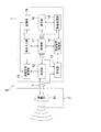
図1は、実施形態に係る超音波診断装置の外観構成を示す概要図である。図2は、実施形態に係る超音波診断装置の電気的な構成を示すブロック図である。 FIG. 1 is a schematic diagram illustrating an external configuration of an ultrasonic diagnostic apparatus according to an embodiment. FIG. 2 is a block diagram illustrating an electrical configuration of the ultrasonic diagnostic apparatus according to the embodiment.
超音波診断装置Sは、図1及び図2に示すように、図略の生体等の被検体Hに対して超音波を送信すると共に、被検体Hで反射した超音波の反射超音波を受信する超音波探触子2と、超音波探触子2とケーブル3を介して接続され、超音波探触子2へケーブル3を介して電気信号の送信信号を送信することによって超音波探触子2に被検体Hに対して超音波を送信させると共に、超音波探触子2で受信された被検体H内からの反射超音波に応じて超音波探触子2で生成された電気信号の受信信号に基づいて被検体H内の内部状態を超音波画像として医用画像に画像化する超音波診断装置本体1とを備えて構成される。
As shown in FIGS. 1 and 2, the ultrasonic diagnostic apparatus S transmits ultrasonic waves to a subject H such as a living body (not shown) and receives reflected ultrasonic waves reflected by the subject H. The
超音波診断装置本体1には、超音波探触子2を使用しない時に、超音波探触子2を保持させておく超音波探触子フォルダ4が備えられている。
The ultrasonic diagnostic apparatus
超音波診断装置本体1は、例えば、図2に示すように、操作入力部11と、送信部12と、受信部13と、受信信号処理部14と、画像処理部15と、表示部16と、制御部17と、記憶部19と、送信信号処理部18と、を備えて構成されている。
For example, as shown in FIG. 2, the ultrasonic diagnostic apparatus
操作入力部11は、例えば、診断開始を指示するコマンドや被検体Hの個人情報等のデータを入力するものであり、例えば、複数の入力スイッチを備えた操作パネルやキーボード等である。
The
送信信号処理部18は、制御部17の制御に従って、振動部40を駆動する電気信号の送信信号を生成する機能を有する回路である。振動部40は二次元的に配置した複数の超音波振動子を有し、送信信号は隣接する振動子に一定の遅れ時間をもって順次連続的に生成されている。
The transmission
送信部12は、送信信号処理部18が生成した電気信号を増幅し、超音波探触子2内の振動部40へ、ケーブル3を介して送信信号を供給し、超音波探触子2に超音波を発生させる。送信部12は、例えば、高電圧のパルスを生成する高圧パルス発生器等を備えて構成される。
The
受信部13は、制御部17の制御に従って、超音波探触子2内の振動部40からケーブル3を介して電気信号の受信信号を受信する回路であり、この受信信号を受信信号処理部14へ出力する。受信部13は、例えば、受信信号を予め設定された所定の増幅率で増幅する増幅器、及び、この増幅器で増幅された受信信号をアナログ信号からデジタル信号へ変換するアナログ−デジタル変換器等を備えて構成される。
The receiving
送信部12からの送信信号で振動部40の超音波振動子が超音波を発振した後に、隣接する振動子で反射波を受信し、受信部13へ受信信号を出力する。この動作が振動部40の配列された超音波振動子に対して、列ごとに短時間に順次実行し、超音波振動子は超音波と電気信号とを順次交互に変換可能となっている。
After the ultrasonic transducer of the
受信信号処理部14は、制御部17の制御に従って、受信部13からの電気信号に、所定の信号処理を施す回路であり、その信号処理した反射受信信号を画像処理部15へ出力する。
The reception
画像処理部15は、制御部17の制御に従って、受信信号処理部14で信号処理された反射受信信号に基づいて、ハーモニックイメージング技術等を用いて被検体H内の内部状態の超音波画像を生成する回路である。また、例えば、反射受信信号に対して包絡線検波処理を施すことにより、反射超音波の振幅強度に対応したBモード信号を生成する。
The
記憶部19はRAMやROMで構成され、制御部17に用いられるプログラムが記録され、また、表示部16で表示する各種画像のテンプレートが記録されている。
The storage unit 19 includes a RAM and a ROM, and stores a program used for the
制御部17は、例えば、マイクロプロセッサ、記憶素子及びその周辺回路等を備えて構成され、これら操作入力部11、送信部12、受信部13、受信信号処理部14、画像処理部15、表示部16、送信信号処理部18、記憶部19を当該機能に応じてそれぞれ制御することによって超音波診断装置Sの全体制御を行う回路である。
The
表示部16は、制御部17の制御に従って、画像処理部15で生成された超音波画像を表示する装置である。表示部16は、例えば、CRTディスプレイ、LCD、ELディスプレイ及びプラズマディスプレイ等の表示装置やプリンタ等の印刷装置等である。
The
ここからは本発明の圧電セラミックスの単板からなるモノリシック圧電材料と、圧電セラミックからなる複数の柱部と該柱部間の間隙を埋められた樹脂部からなるコンポジット圧電材料とを交互に複数を積層し、積層の層間および両端に電極を備えた積層型超音波振動子と、積層型超音波振動子を用いた探触子について説明する。 From here on, a plurality of monolithic piezoelectric materials composed of a single plate of the piezoelectric ceramic of the present invention and composite piezoelectric materials composed of a plurality of pillar portions made of piezoelectric ceramic and a resin portion filled with a gap between the pillar portions are alternately arranged. A description will be given of a laminated ultrasonic transducer having electrodes laminated on and between the laminated layers and at both ends, and a probe using the laminated ultrasonic transducer.
図3は積層型振動子40aを同一平面上に二次元的に配置した振動部40の斜視図である。
FIG. 3 is a perspective view of the
支持部材であるバッキング層40a8上には、複数の積層型振動子40aが一定の間隔を空けてマトリックス状に配列されている。
On the backing layer 40a8, which is a support member, a plurality of stacked
バッキング層40a8は超音波を吸収する材料から構成された平板状の部材であり、積層型振動子40aからバッキング層40a8方向へ放射される超音波を吸収するものである。
The backing layer 40a8 is a flat plate member made of a material that absorbs ultrasonic waves, and absorbs ultrasonic waves radiated from the
図示では4×7のマトリックスを示しているが、この配列に限定されるものではない。 Although a 4 × 7 matrix is shown in the drawing, the present invention is not limited to this arrangement.
図4は積層型振動子40aの斜視図である。上段から第2音響整合層40a1、第1音響整合層40a2、第1電極40a3、PZTコンポジット40a4、第2電極40a6、PZTモノリシック40a5、第1電極40a3、PZTコンポジット40a4、第2電極40a6、反射層40a7の積層をなしている。また、図示しない保護層があってもよい。
FIG. 4 is a perspective view of the
コンポジット圧電材料であるPZTコンポジット40a4とモノリシック圧電材料であるPZTモノリシック40a5は同様の共振周波数を有し、互いに共振可能であることにより各々の電極部が超音波振動の節部または腹部となり、積層型の構造のメリットを生かした、大きな出力を得ることができる。 The PZT composite 40a4, which is a composite piezoelectric material, and the PZT monolithic 40a5, which is a monolithic piezoelectric material, have the same resonance frequency and can resonate with each other, whereby each electrode portion becomes a node portion or an abdomen portion of ultrasonic vibration. Large output can be obtained by taking advantage of the structure.
音波は界面での媒質の音響インピーダンスZ(密度×音速)の差が大きいと反射率が高くなって音波が放射されないため、圧電材料と被検体(例えば生体)の間を音響整合層で段階的に音響インピーダンスを変化させて音波の透過率を上げるための音響整合層を設け、第1音響整合層40a2では樹脂にタングステンを添加(密度・音速アップ)することにより、やや圧電材料寄りの音響インピーダンスとし、その上層(生体側)の第2音響整合層40a1は樹脂のみで形成することにより生体寄りの音響インピーダンスにして階段状に繋いでいる。 If the difference in acoustic impedance Z (density x speed of sound) of the medium at the interface is large, the sound wave is reflected and the sound wave is not radiated. The first acoustic matching layer 40a2 is provided with an acoustic matching layer for changing the acoustic impedance to increase the sound wave transmittance. By adding tungsten to the resin (increasing density and sound speed), the acoustic impedance slightly closer to the piezoelectric material is obtained. The second acoustic matching layer 40a1 on the upper layer (living body side) is formed of only a resin, and is connected in a staircase pattern to a living body-oriented acoustic impedance.
第1電極40a3と第2電極40a6は、圧電材料であるPZTコンポジット40a4およびPZTモノリシック40a5の厚さ方向に交互に積層して配置した構造をしている。 The first electrode 40a3 and the second electrode 40a6 have a structure in which they are alternately stacked in the thickness direction of the PZT composite 40a4 and the PZT monolithic 40a5 that are piezoelectric materials.
第1電極40a3は圧電材料の第1層目であるPZTコンポジット40a4の上面に接し、第2層目のPZTモノリシック40a5の下面に接している。同様に第2電極40a6は第2層目のPZTモノリシック40a5の上面に接し、第3層目のPZTコンポジット40a4の下面に接している。 The first electrode 40a3 is in contact with the upper surface of the PZT composite 40a4 that is the first layer of the piezoelectric material, and is in contact with the lower surface of the second layer PZT monolithic 40a5. Similarly, the second electrode 40a6 is in contact with the upper surface of the second-layer PZT monolithic 40a5 and in contact with the lower surface of the third-layer PZT composite 40a4.
このように圧電材料の積層の層間および両端に電極を持ち、互いに隣り合う圧電材料の積層において、離反側の電極が連結配線された構造をなしている。 In this way, the structure has a structure in which electrodes are provided between the layers and both ends of the piezoelectric material stack, and the electrodes on the separation side are connected and connected in the stack of adjacent piezoelectric materials.
圧電材料の上部部材(整合層がこれに相当)および下部部材(バッキング層がこれに相当)ともに音響インピーダンスが圧電材料より低く、圧電材料の共振モードはλ/2共振(上部/下部とも自由端振動)となる。そのために圧電材料である第3層目のPZTコンポジット40a4とバッキング層40a8間に、圧電材料より高い音響インピーダンスを持つタングステンカーバイド材料とする反射層40a7をもうけることにより、共振モードはλ/4共振(上部自由端、下部固定端)となることに加え、従来バッキング側に放射され、バッキング層で吸収して熱として排出されていた音波のエネルギーの多くが前面に放射されるようになって、音響強度(感度)が約2倍となる効果がでる。 The piezoelectric member upper member (matching layer is equivalent to this) and the lower member (backing layer is equivalent to this) have an acoustic impedance lower than that of the piezoelectric material, and the resonance mode of the piezoelectric material is λ / 2 resonance (both upper and lower parts are free ends) Vibration). Therefore, by providing a reflective layer 40a7, which is a tungsten carbide material having an acoustic impedance higher than that of the piezoelectric material, between the third PZT composite 40a4 and the backing layer 40a8, which is a piezoelectric material, the resonance mode is λ / 4 resonance ( In addition to becoming the upper free end and the lower fixed end), much of the energy of the sound wave that has been radiated to the backing side and absorbed by the backing layer and discharged as heat is radiated to the front surface. The strength (sensitivity) is approximately doubled.
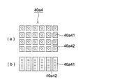
図5aは第1層目と第3層目に設けられたPZTコンポジット40a4の図4で示すA方向からの水平方向の断面図である。また図5bは垂直方向の断面図である。 FIG. 5A is a horizontal cross-sectional view from the A direction shown in FIG. 4 of the PZT composite 40a4 provided in the first layer and the third layer. FIG. 5b is a vertical cross-sectional view.
PZT柱部40a41は柱状をなし、PZT柱部40a41の夫々が隣り合う空間にはエポキシ樹脂を材料とする樹脂部40a42が充填され、板状の圧電材料をなしている。 The PZT column portion 40a41 has a columnar shape, and a space in which each of the PZT column portions 40a41 is adjacent is filled with a resin portion 40a42 made of an epoxy resin, thereby forming a plate-like piezoelectric material.
このように圧電部を積層することで静電容量が確保でき、被検体からみた2Dマトリクスアレイ式の圧電部の小面積化による容量低下が招く探触子(振動子)と診断装置間の伝送線路浮遊容量の影響を受けやすい問題を回避することができる。 By stacking the piezoelectric parts in this manner, the capacitance can be secured, and the transmission between the probe (vibrator) and the diagnostic device causes the capacity to decrease due to the reduction in area of the 2D matrix array type piezoelectric part viewed from the subject. Problems that are easily affected by the stray capacitance can be avoided.
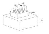
図6はPZTコンポジット40a4の製造方法の一例を表した図である。 FIG. 6 is a diagram showing an example of a manufacturing method of the PZT composite 40a4.
図6に示すようにPZT単板200を切断用基板100に仮接着を行い、ダイアモンドカッターなどで切断線y1、y2、y3および切断線x1、x2からx5とダイシングし、切断溝にセラミック樹脂等を充填し固化させる。その後、仮接着した切断用基板を取り外して、PZTコンポジット40a4の圧電材料を得る。
As shown in FIG. 6, the PZT
以下、本発明を実施例により説明するが、本発明はこれに限定されるものではない。 EXAMPLES Hereinafter, although an Example demonstrates this invention, this invention is not limited to this.
(実施例1)
第2音響整合層40a1にエポキシ樹脂を材料とし、厚さは180μm、第1音響整合層40a2はエポキシ樹脂にタングステンを添加したものを厚さ120μm積層する。第1層および第3層の圧電材料は、図5aで示す断面の断面積全体に対するPZTの断面積が占める割合である占積率を76%としたPZTコンポジット、第2層の圧電材料はPZTの占積率を100%としたPZTモノリシックを夫々280μmの厚さで積層する。反射層40a7はタングステンカーバイドを材料とし、厚さ50μmで積層し、支持部材であるバッキング層にフェライトゴム(スピネルフェライト質量85%)を用いる。
Example 1
The second acoustic matching layer 40a1 is made of an epoxy resin and has a thickness of 180 μm, and the first acoustic matching layer 40a2 is a laminate of epoxy resin added with tungsten having a thickness of 120 μm. The piezoelectric material of the first layer and the third layer is a PZT composite in which the space factor, which is the ratio of the cross-sectional area of PZT to the entire cross-sectional area of the cross section shown in FIG. PZT monolithic with a space factor of 100% is laminated with a thickness of 280 μm. The reflective layer 40a7 is made of tungsten carbide, laminated with a thickness of 50 μm, and ferrite rubber (spinel ferrite mass 85%) is used for the backing layer as a support member.
(実施例2)
圧電材料層の第1層および第3層にPZTの占積率を100%としたPZTモノリシックを用い、圧電材料層の第2層にPZTの占積率を76%としたPZTコンポジットを用いる。圧電材料層の厚みは実施例1と同様である。
(Example 2)
A PZT monolithic with a PZT space factor of 100% is used for the first and third layers of the piezoelectric material layer, and a PZT composite with a PZT space factor of 76% is used for the second layer of the piezoelectric material layer. The thickness of the piezoelectric material layer is the same as in Example 1.
また、第2音響整合層40a1、第1音響整合層40a2、反射層40a7、バッキング層それぞれの材料および厚みは実施例1と同様である。 The materials and thicknesses of the second acoustic matching layer 40a1, the first acoustic matching layer 40a2, the reflective layer 40a7, and the backing layer are the same as those in the first embodiment.
(実施例3)
圧電材料層の第1層および第3層にPZTの占積率68%としたPZTコンポジット、第2層PZTに占積率を100%としたPZTモノリシックを用いた。圧電材料層の厚みは実施例1および2と同様である。
(Example 3)
A PZT composite with a PZT space factor of 68% was used for the first and third layers of the piezoelectric material layer, and a PZT monolithic with a space factor of 100% was used for the second layer PZT. The thickness of the piezoelectric material layer is the same as in Examples 1 and 2.
また、第2音響整合層40a1、第1音響整合層40a2、反射層40a7、バッキング層それぞれの材料および厚みは実施例1および2と同様である。 The materials and thicknesses of the second acoustic matching layer 40a1, the first acoustic matching layer 40a2, the reflective layer 40a7, and the backing layer are the same as those in the first and second embodiments.
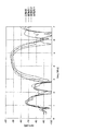
以下、積層型超音波振動子の実施例1から3の確認結果を図7の表および図8のグラフで示す。 Hereinafter, the confirmation results of Examples 1 to 3 of the laminated ultrasonic transducer are shown in the table of FIG. 7 and the graph of FIG.
比較確認のために圧電材料層の第1層、第2層および第3層にPZTの占積率を100%としたPZTモノリシックを用いた。圧電材料層の厚みは実施例と同様であり、第2音響整合層40a1、第1音響整合層40a2、反射層40a7、バッキング層それぞれの材料および厚みは実施例と同様である。 For comparison and confirmation, PZT monolithic with a PZT space factor of 100% was used for the first, second, and third layers of the piezoelectric material layer. The thickness of the piezoelectric material layer is the same as in the example, and the materials and thicknesses of the second acoustic matching layer 40a1, the first acoustic matching layer 40a2, the reflective layer 40a7, and the backing layer are the same as in the example.
測定方法は鏡面鉄板反射による送受信感度の測定を実施した。 As a measuring method, transmission / reception sensitivity was measured by reflection on a mirror surface iron plate.
比較例では−48dBの最大感度であったが、実施例1および2では3dBの感度アップが得られ、実施例3では1dBの感度ダウンとなった。 Although the maximum sensitivity was -48 dB in the comparative example, the sensitivity was increased by 3 dB in Examples 1 and 2, and the sensitivity was decreased by 1 dB in Example 3.
また、図8の比較例および実施例1から3の夫々のグラフのピーク値に対して、−6dB以上の周波数範囲のfL(下限周波数)、fH(上限周波数)、(fL+fH)/2で表されるfC(中心周波数)から有効な帯域幅を比較すると、実施例1および3では1.79MHz(5.34−3.55)、実施例2では1.53MHz(5.22−3.69)が得られ、比較例の1.37MHz(5.12−3.75)に比べ広帯域になっている。 Further, the peak values of the comparative example of FIG. 8 and the graphs of Examples 1 to 3 are expressed as fL (lower limit frequency), fH (upper limit frequency), and (fL + fH) / 2 in a frequency range of −6 dB or more. When the effective bandwidth is compared from the calculated fC (center frequency), 1.79 MHz (5.34 to 3.55) in Examples 1 and 3 and 1.53 MHz (5.22 to 3.69) in Example 2 are compared. ), Which is a wider band than the 1.37 MHz (5.12-3.75) of the comparative example.
同様に周波数帯域率BW(%)=(fH−fL)/fC × 100は、比較例の31%に対して、実施例1および3では40%、実施例2では34%と広い帯域率が得られた。 Similarly, the frequency bandwidth ratio BW (%) = (fH−fL) / fC × 100 is 40% in Examples 1 and 3 and 34% in Example 2 compared to 31% in the comparative example. Obtained.
このようにコンポジット圧電材料とモノリシック圧電材料を交互に積層した積層型超音波振動子では感度や周波数帯域に優れ、特にPZT占積率が76%のコンポジット圧電材料を第1層および第3層に備え、第2層にモノリシック圧電材料を備えた超音波振動子では大幅な改善を図ることができることが確認された。なお、PZT占積率は76%に限定されるものではない。 As described above, the laminated ultrasonic transducer in which the composite piezoelectric material and the monolithic piezoelectric material are alternately laminated is excellent in sensitivity and frequency band. In particular, the composite piezoelectric material having a PZT space factor of 76% is used in the first layer and the third layer. In addition, it was confirmed that the ultrasonic vibrator provided with the monolithic piezoelectric material in the second layer can greatly improve. The PZT space factor is not limited to 76%.
このようなコンポジット圧電材料とモノリシック圧電材料を交互に積層した積層型超音波振動子では電気特性と音響特性に優れ、積層型超音波振動子備えることで、高解像度の画像を得ることができる超音波探触子およびこの超音波探触子を備えた超音波診断装置を得ることが可能となる。 Such a laminated ultrasonic transducer in which a composite piezoelectric material and a monolithic piezoelectric material are alternately laminated is excellent in electrical characteristics and acoustic characteristics. By providing a laminated ultrasonic transducer, a super-resolution image can be obtained. It is possible to obtain an ultrasonic probe and an ultrasonic diagnostic apparatus including the ultrasonic probe.
1 超音波診断装置本体
2 超音波探触子
3 ケーブル
4 超音波プローブフォルダ
11 操作入力部
12 送信部
13 受信部
14 受信信号処理部
15 画像処理部
16 表示部
17 制御部
18 送信信号処理部
19 記憶部
40 振動部
40a 積層型振動子
40a1 第2音響整合層
40a2 第1音響整合層
40a3 第1電極
40a4 PZTコンポジット
40a5 PZTモノリシック
40a6 第2電極
40a7 反射層
40a8 バッキング層
40a41 PZT柱部
40a42 樹脂部
H 被検体
S 超音波診断装置
DESCRIPTION OF
Claims (5)
圧電セラミックの単板からなるモノリシック圧電材料の層と、圧電セラミックからなる複数の柱部と該柱部間の間隙を埋められた樹脂部とを備えるコンポジット圧電材料の層と、を交互に3層以上重ねられた積層と、
該積層の層間および両端に設けられた電極と、を有し、
互いに隣り合う圧電材料の層における離反側の電極は連結配線されていることを特徴とする超音波振動子。 An ultrasonic transducer that transmits or receives ultrasonic waves and can alternately convert electrical signals and ultrasonic waves,
Three layers of alternating layers of a monolithic piezoelectric material made of a piezoelectric ceramic single plate and a composite piezoelectric material layer comprising a plurality of pillar parts made of piezoelectric ceramic and a resin part filled with a gap between the pillar parts A layered stack, and
Electrodes provided on the interlayer and both ends of the laminate,
An ultrasonic vibrator, wherein electrodes on the separation side in layers of piezoelectric materials adjacent to each other are connected and connected.
Priority Applications (1)
| Application Number | Priority Date | Filing Date | Title |
|---|---|---|---|
| JP2011001036A JP2012142880A (en) | 2011-01-06 | 2011-01-06 | Ultrasonic vibrator, ultrasonic probe and ultrasonic diagnostic apparatus |
Applications Claiming Priority (1)
| Application Number | Priority Date | Filing Date | Title |
|---|---|---|---|
| JP2011001036A JP2012142880A (en) | 2011-01-06 | 2011-01-06 | Ultrasonic vibrator, ultrasonic probe and ultrasonic diagnostic apparatus |
Publications (1)
| Publication Number | Publication Date |
|---|---|
| JP2012142880A true JP2012142880A (en) | 2012-07-26 |
Family
ID=46678692
Family Applications (1)
| Application Number | Title | Priority Date | Filing Date |
|---|---|---|---|
| JP2011001036A Pending JP2012142880A (en) | 2011-01-06 | 2011-01-06 | Ultrasonic vibrator, ultrasonic probe and ultrasonic diagnostic apparatus |
Country Status (1)
| Country | Link |
|---|---|
| JP (1) | JP2012142880A (en) |
Cited By (1)
| Publication number | Priority date | Publication date | Assignee | Title |
|---|---|---|---|---|
| JP2014107853A (en) * | 2012-11-30 | 2014-06-09 | Konica Minolta Inc | Ultrasonic probe |
-
2011
- 2011-01-06 JP JP2011001036A patent/JP2012142880A/en active Pending
Cited By (1)
| Publication number | Priority date | Publication date | Assignee | Title |
|---|---|---|---|---|
| JP2014107853A (en) * | 2012-11-30 | 2014-06-09 | Konica Minolta Inc | Ultrasonic probe |
Similar Documents
| Publication | Publication Date | Title |
|---|---|---|
| Lee et al. | Ultrasonic transducers for medical diagnostic imaging | |
| US7679270B2 (en) | Ultrasonic probe | |
| KR102044705B1 (en) | Ultrasonic transducer having matching layer having composite structure and method for manufacturing same | |
| JP5582139B2 (en) | Ultrasonic probe and ultrasonic diagnostic apparatus | |
| JP2009296055A (en) | Ultrasonic probe and ultrasonic diagnostic apparatus using the same | |
| US9839411B2 (en) | Ultrasound diagnostic apparatus probe having laminated piezoelectric layers oriented at different angles | |
| JP2009213137A (en) | Apparatus and method for increasing sensitivity of ultrasound transducers | |
| KR101296244B1 (en) | Backing element of ultrasonic probe, backing of ultrasonic probe and manufacturing method thereof | |
| JP2008048276A (en) | Ultrasonic transducer and ultrasonic transducer array | |
| JP5504921B2 (en) | Ultrasonic probe and ultrasonic diagnostic apparatus | |
| JP2011010794A (en) | Ultrasonic probe and ultrasonic diagnostic apparatus equipped with the same | |
| US8876718B2 (en) | Ultrasound diagnostic apparatus and ultrasound image generating method | |
| JP5552820B2 (en) | Ultrasonic probe and ultrasonic diagnostic apparatus | |
| JP2012142880A (en) | Ultrasonic vibrator, ultrasonic probe and ultrasonic diagnostic apparatus | |
| JP2012129595A (en) | Ultrasonic probe and method of manufacturing ultrasonic probe | |
| JP2009260481A (en) | Sound damping member, method for manufacturing of sound damping member, ultrasonic probe and ultrasonic diagnostic apparatus | |
| WO2001056474A1 (en) | Ultrasonic probe and ultrasonic diagnostic device comprising the same | |
| JP5917718B2 (en) | Ultrasonic diagnostic equipment | |
| JP2012011024A (en) | Ultrasonic probe and ultrasonic diagnostic apparatus | |
| JP2009268807A (en) | Ultrasonic diagnostic device | |
| JP2010219774A (en) | Ultrasound transducer, ultrasound probe, and ultrasound diagnostic apparatus | |
| JP2009201053A (en) | Ultrasonic probe, manufacturing method thereof and ultrasonic diagnostic device using the ultrasonic probe | |
| Li | Micromachined piezoelectric material and dual-layer transducers for ultrasound imaging | |
| JP5299128B2 (en) | Ultrasonic probe, ultrasonic diagnostic equipment | |
| JP2010213766A (en) | Ultrasonic probe and ultrasonic diagnosis apparatus |
Legal Events
| Date | Code | Title | Description |
|---|---|---|---|
| A711 | Notification of change in applicant |
Free format text: JAPANESE INTERMEDIATE CODE: A712 Effective date: 20130415 |