JP2012142679A - Video telephone apparatus - Google Patents
Video telephone apparatus Download PDFInfo
- Publication number
- JP2012142679A JP2012142679A JP2010292266A JP2010292266A JP2012142679A JP 2012142679 A JP2012142679 A JP 2012142679A JP 2010292266 A JP2010292266 A JP 2010292266A JP 2010292266 A JP2010292266 A JP 2010292266A JP 2012142679 A JP2012142679 A JP 2012142679A
- Authority
- JP
- Japan
- Prior art keywords
- image data
- display
- video
- image
- unit
- Prior art date
- Legal status (The legal status is an assumption and is not a legal conclusion. Google has not performed a legal analysis and makes no representation as to the accuracy of the status listed.)
- Pending
Links
Images


Landscapes
- Telephone Function (AREA)
- Editing Of Facsimile Originals (AREA)
- Two-Way Televisions, Distribution Of Moving Picture Or The Like (AREA)
Abstract
Description
本発明は、IP電話網等に接続されて音声及び映像の送受信を行うテレビ電話装置に関し、特に、通話相手先のテレビ電話装置から送信されてきた画像データを通話中に編集・加工し、さらに返信することが可能なテレビ電話装置に関する。 The present invention relates to a videophone apparatus that is connected to an IP telephone network or the like and transmits and receives audio and video, and in particular, edits and processes image data transmitted from a videophone apparatus of a call partner during a call, The present invention relates to a videophone device capable of replying.
近年、通信インフラの発達に伴い、通信に関する様々な付加サービスが普及するようになってきた。例えば、電話装置においては、一般電話回線以外に、IP電話網やインターネット等の広域通信網に接続して、データ通信サービス等の様々なサービスを受けることが可能な電話装置が普及している。 In recent years, with the development of communication infrastructure, various additional services related to communication have come into wide use. For example, telephone devices that can receive various services such as a data communication service by connecting to a wide-area communication network such as an IP telephone network or the Internet in addition to a general telephone line are widely used.
このような電話装置に対するサービスとして、テレビ電話サービスが実用化されている。テレビ電話サービスの利用者は、カメラ機能及び画像送信機能を備えたテレビ電話装置を通信回線に接続することにより、撮影された映像の送受信を行いながら音声通話を行うことが可能である。 As a service for such a telephone device, a videophone service has been put into practical use. A user of a videophone service can make a voice call while transmitting and receiving a captured video by connecting a videophone device having a camera function and an image transmission function to a communication line.
こうした撮影映像に加えて、他の画像データを通話相手先に送信可能なテレビ電話装置も開発されている。例えば、下記特許文献1(特開2004−228805号公報)は、テレビ電話の通話中に会話に関連する特定の画像データ等を会話と同時進行でマルチタスクによりネットワーク等を介して取得し、その画像データを通話中の相手局に送信することが可能なテレビ電話機能を開示している。 In addition to such photographed video, a videophone device capable of transmitting other image data to a call partner has been developed. For example, the following Patent Document 1 (Japanese Patent Application Laid-Open No. 2004-228805) acquires specific image data related to a conversation during a videophone call over a network or the like by multitasking simultaneously with the conversation. A videophone function capable of transmitting image data to a partner station during a call is disclosed.
このテレビ電話機能は、テレビ電話機能手段と、データ通信機能手段と、マルチアクセス機能手段と、を備える。テレビ電話機能手段は、通話中に撮像部により撮影された映像をテレビ電話機能手段によって相手局に送信するとともに相手局から送信された映像を受信し表示部に出力する。また、データ通信機能手段は所定のホームページ等に接続し文字や画像の表示情報を取得するデータ通信を行う。マルチアクセス機能手段は、テレビ電話機能手段とデータ通信機能手段とを同時に稼動させるためのものである。データ通信によって取得された表示情報は、映像、音声とともに、相手局に送信され、相手局において表示される。 This videophone function includes videophone function means, data communication function means, and multi-access function means. The videophone function means transmits the video taken by the imaging unit during a call to the other station by the videophone function means and receives the video transmitted from the other station and outputs it to the display unit. The data communication function means connects to a predetermined homepage or the like and performs data communication for acquiring display information of characters and images. The multi-access function means is for operating the videophone function means and the data communication function means simultaneously. Display information acquired by data communication is transmitted to the partner station together with video and audio, and displayed at the partner station.
上記特許文献1のテレビ電話機能は、撮影した映像を送信することに加えて通話中に画像等のデータを送信することが可能であるが、通話相手先では、受信した画像等のデータを参照することはできたとしても、さらにそれを編集したり加工したりし、編集・加工後の画像を再び通話元に返信することはできなかった。 The videophone function disclosed in Patent Document 1 can transmit data such as images during a call in addition to transmitting captured video, but the other party refers to the received data such as images. Even if they were able to do so, they could not edit or process it further, and could not send the edited / modified image back to the caller again.
通話中に受信した画像等のデータを編集・加工し、それを返信することができれば、通話者同士はさらに十分な意思の疎通が可能となり、明確で誤りの少ない会話を行うことが可能となる。 If data such as images received during a call can be edited / processed and sent back, the callers can communicate with each other more fully and can have a clear and error-free conversation. .
そこで、本発明の目的は、テレビ電話装置において、通話中に撮影映像及び画像等のデータの送受信を行うことに加えて、受信した画像等のデータを編集・加工し、編集・加工されたデータをさらに通話相手先に送信する機能を提供することである。 Therefore, an object of the present invention is to edit and process data such as received images in addition to performing transmission and reception of data such as captured video and images during a call in a videophone device. Is to provide a function for further transmitting to the other party.
上記課題を解決するために本発明のテレビ電話装置は、表示部と、入力部と、マイクと、スピーカと、カメラと、通信回線における送受信の制御を行う通信制御手段、前記マイクから入力された音声を、通信回線送信用のデータ形式に変換するとともに前記通信回線から受信した音声信号を変換して前記スピーカに出力する音声信号処理手段、画像データ及び/又は前記カメラにおいて撮像された映像を、通信回線送信用のデータ形式に変換するとともに前記通信回線から受信した画像データ及び/又は映像信号を変換して表示制御手段に出力する画像・映像信号処理手段、前記映像信号と前記画像データを前記表示部に表示可能な態様に変換して前記表示部に表示する表示制御手段、前記画像データを、前記入力部からの指示に基づいて編集する画像編集手段、を有する制御部と、を備えるテレビ電話装置であって、前記通話相手先から通信回線を介して受信した画像データを、前記画像編集手段が前記入力部からの指示に基づいて編集することを特徴とする。 In order to solve the above problems, a videophone device according to the present invention includes a display unit, an input unit, a microphone, a speaker, a camera, communication control means for controlling transmission / reception in a communication line, and input from the microphone. Audio signal processing means for converting audio into a data format for communication line transmission and converting an audio signal received from the communication line and outputting it to the speaker, image data and / or video captured by the camera, An image / video signal processing means for converting the image data and / or video signal received from the communication line into a data format for communication line transmission and outputting to the display control means, the video signal and the image data Display control means for converting to a form that can be displayed on the display unit and displaying on the display unit, editing the image data based on an instruction from the input unit And a control unit having an image editing unit, wherein the image editing unit receives image data received from the communication partner via a communication line based on an instruction from the input unit. It is characterized by editing.
また、本発明のテレビ電話装置の一態様は、前記通信回線を介して受信した画像データを、前記入力部からの指示に基づいて前記画像編集手段によって編集した後に、前記入力部からの指示に基づいて前記通信回線を介して通話相手先に送信することを特徴とする。 According to another aspect of the videophone device of the present invention, the image data received via the communication line is edited by the image editing unit based on an instruction from the input unit, and then the instruction from the input unit is received. And transmitting to the other party via the communication line.
また、本発明のテレビ電話装置の一態様は、前記画像編集手段が、入力部からの指示に基づいて前記画像データに所定の図形及び/又は文字を描画することを特徴とする。 According to another aspect of the videophone apparatus of the present invention, the image editing unit draws a predetermined figure and / or character on the image data based on an instruction from an input unit.
また、本発明のテレビ電話装置の一態様は、前記表示制御手段が、前記表示部を、前記映像と前記画像データとが同時に表示される表示構成とすることを特徴とする。 In one aspect of the videophone apparatus of the present invention, the display control means has a display configuration in which the display unit displays the video and the image data simultaneously.
また、本発明のテレビ電話装置の一態様は、前記表示制御手段が、前記表示部を、前記編集中の画像データを表示する第1の領域と、前記通話相手先から前記受信された画像データとを表示する第2の領域とを含む表示構成とすることを特徴とする。 According to another aspect of the videophone apparatus of the present invention, the display control unit displays the display unit on the first area for displaying the image data being edited and the image data received from the other party. And a second area for displaying the display area.
本発明は、以下に説明する優れた効果を発揮する。すなわち、本発明のテレビ電話装置は、マイクから入力された音声、カメラにおいて撮影された映像、また本装置において編集された画像データを通信回線送信用のデータ形式に変換して通話相手先に送信することができる。また、通話相手先から送信されてきた音声信号をスピーカから出力し、映像、画像データを表示手段に表示できる。さらに、本発明のテレビ電話装置は画像編集手段を備えているので、通話相手先より受信し表示手段に表示された画像データを、入力部からの指示に基づいて編集することが可能となる。 The present invention exhibits the excellent effects described below. In other words, the videophone device of the present invention converts audio input from a microphone, video captured by a camera, and image data edited by this device into a data format for communication line transmission, and transmits the data to the other party. can do. In addition, an audio signal transmitted from the other party can be output from the speaker, and video and image data can be displayed on the display means. Further, since the videophone device of the present invention includes the image editing means, it is possible to edit the image data received from the call partner and displayed on the display means based on an instruction from the input unit.
また、本発明のテレビ電話装置の一態様によれば、通信回線を介して受信した画像を入力部からの指示に基づいて編集した後に、入力部からの指示に基づいて編集された画像を通話相手先に送信することができる。これにより、通話相手先から受信した画像を編集して再び通話相手先に送信できるようになるから、通話者同士は、編集後の同じ画像データを共有することができる。これにより、通話者同士でより明確で誤りの少ない会話を行うことが可能となり、十分な意思の疎通を達成することが可能となる。 Further, according to one aspect of the videophone device of the present invention, an image received via a communication line is edited based on an instruction from the input unit, and then the image edited based on the instruction from the input unit is called. Can be sent to the other party. As a result, the image received from the call partner can be edited and transmitted again to the call partner, so that the callers can share the same edited image data. As a result, it is possible to have a clearer and less error-free conversation between the callers, and to achieve sufficient communication.
また、本発明のテレビ電話装置の一態様によれば、編集する画像データに所定の図形や文字を入力することができ、ユーザにとって編集が容易に行えるようになる。 In addition, according to one aspect of the videophone device of the present invention, it is possible to input a predetermined figure or character to the image data to be edited, so that the user can easily edit.
また、本発明のテレビ電話装置の一態様によれば、編集する画像データと、通話相手先から受信した映像とを同時に表示することができる。これにより、受信した映像、例えば、通話相手の顔を見ながら画像データを編集することが可能となり、意思の疎通を十分に図るための助けとなる。 In addition, according to one aspect of the videophone device of the present invention, it is possible to simultaneously display image data to be edited and video received from a call partner. As a result, it is possible to edit the received video, for example, image data while looking at the face of the other party, which is helpful for sufficient communication.
また、本発明のテレビ電話装置の一態様によれば、編集中の画像データと、通話相手先から受信した画像データとを同時に表示することができる。これにより、互いの画像データを比較しながら編集や通話を行うことが可能となる。 Further, according to one aspect of the videophone device of the present invention, it is possible to simultaneously display image data being edited and image data received from the other party. This makes it possible to perform editing and talking while comparing each other's image data.
以下、本願発明を実施するための最良の形態を実施例及び図面を参照して詳細に説明する。ただし、以下に示す実施例は、本発明の技術思想を具体化するためのテレビ電話装置を例示して説明するものであって、本発明をこのテレビ電話装置に特定することを意図するものではなく特許請求の範囲に示した技術思想を逸脱することなくその他のテレビ電話装置にも等しく適用し得るものである。 Hereinafter, the best mode for carrying out the present invention will be described in detail with reference to examples and drawings. However, the following embodiments are described by exemplifying a videophone device for embodying the technical idea of the present invention, and are not intended to specify the present invention as this videophone device. The present invention is equally applicable to other videophone devices without departing from the technical idea described in the claims.
図1は、本発明のテレビ電話装置を含む通信システム1の構成を示すブロック図である。本システムは少なくとも、テレビ電話装置100、有線LAN101、IP電話ルータ102、ブロードバンドルータ103、ゲートウェイ104、IP電話網105、インターネット106、PSTN網107(=Public Switched Telephone Network:公衆電話交換網)、及び加入者電話装置108を含むように構成されている。
FIG. 1 is a block diagram showing a configuration of a communication system 1 including a videophone device according to the present invention. The system includes at least a
本発明のテレビ電話装置100は有線LAN101に接続され、有線LAN101は、IP電話ルータ102を介してIP電話網105に、ブロードバンドルータ103を介してインターネット106に、ゲートウェイ104を介してPSTN網107にそれぞれ接続されることにより、通信が可能である。なお、テレビ電話装置1の内部構造の詳細については後述する。
The
有線LAN101を構成する物理的な手段としては、例えばツイストペアケーブルを用いた10BASE−T(IEEE802.3iとして標準化)や100BASE−TX(IEEE802.3uとして標準化)等があげられる。
Examples of physical means constituting the
IP電話ルータ102、及びブロードバンドルータ103は、複数のIPネットワークを相互接続するためのネットワーク中継装置である。具体的には、OSI(Open Systems Interconnection)参照モデルでいうネットワーク層(第3層)やトランスポート層(第4層)の一部のプロトコルを解析して転送を行う。
The
本実例では、IP電話ルータ102は有線LAN101とIP電話網105との二つのIPネットワークを相互に接続する役割を持つ。またブロードバンドルータ103は、有線LAN101とインターネット106との二つのIPネットワークを相互に接続する役割を持つ。
In this example, the
ゲートウェイ104は、プロトコル体系が異なるネットワーク間を相互接続するためのプロトコル変換器である。ゲートウェイ104は、例えば、有線LAN101とPSTN網107とを接続し、SIP等のシグナリングプロトコルを用いてシグナル変換を行うことにより、両ネットワーク間での通信を可能とする。
The
IP電話網105は、電話網の一部もしくは全てにVoIP(Voice over Internet Protocol)技術を利用した通信網であり、用いる通信回線としてはFTTH(Fiber To The Home)やADSL(Asymmetric Digital Subscriber Line)等の、いわゆるブロードバンド回線が利用される。なお、IP電話網105にはテレビ電話装置100’が複数接続されているが、図1では簡単のため1台のみしか描写されていない。
The
なおVoIPとは、音声を各種符号化方式で圧縮した後にパケットに分割し、IPネットワークでリアルタイム伝送する技術である。これによりIP電話網105は音声通話サービスの他、画像の送受信を行うテレビ電話サービス等が提供可能となる。
Note that VoIP is a technique in which voice is compressed by various encoding methods, divided into packets, and transmitted in real time over an IP network. As a result, the
インターネット106は、通信プロトコルによるネットワークを相互接続して構築された広域通信網である。大小様々なコンピュータネットワークを相互に連結させて、国際的な通信ネットワークが構築されている。通信プロトコルとしては主に、TCP/IPが標準的なプロトコルとして採用されている。
The
PSTN網107は、一般の加入者電話回線ネットワークである。末端に加入者電話装置108を接続し、回線交換方式で通信相手に接続して音声通話を行うのに用いられる。加入者電話装置108は、電話加入者がPSTN網107を用いてPSTN網に接続された他の加入者電話装置や有線LAN101やIP電話網105に接続されたテレビ電話装置と音声通話を行うための電話装置である。
The
次に、図2を参照して本実施例のテレビ電話装置100について説明する。なお、図2は本実施例に係るテレビ電話装置100の構成を示す内部ブロック図である。テレビ電話装置100は、制御部110、マイク120、スピーカ130、カメラ140、表示部150、入力部160、メモリ170を備えて構成される。
Next, the
制御部110は、CPU、RAM、ROMを備えて構成されるマイクロプロセッサであり、RAMやROMに記憶された制御プログラムをCPUにおいて実行することにより、以下に説明する各手段の動作を制御・統括する。
The
制御部110は、通信制御手段111、音声信号処理手段112、画像・映像信号処理手段113、表示制御手段114、画像編集手段115、データ制御手段116、時刻制御手段117を備えて構成される。
The
通信制御手段111は、テレビ電話装置100が他のテレビ電話装置100’と通信を行う際の通信制御を行うためのものである。これには、シグナリングとデータの送受信とに関わる制御が含まれる。シグナリングには通信セッションの生成、確立、切断が含まれる。具体的には、ユーザが入力部160を操作して電話番号等を入力した際に、IP電話網105に接続されたSIPサーバ(図示せず)等に接続して通話相手先のテレビ電話装置100’の位置情報を入手するとともに、通話相手先のテレビ電話装置100’を呼出し、通話相手先が応答した場合に通信経路を確立することと、通話が終了した際にセッション切断メッセージ等を送信することによってセッションを終了することが含まれる。
The communication control means 111 is for performing communication control when the
データの送受信に関わる制御には、音声データ、映像データ、画像データをパケットに分割するIPパケット化と及びIPパケットの送信、有線LAN101を介して受信したパケットを、正しい順序に並べ替えるとともに実際のデータ部分を抽出して組立てるIPパケットの受信及び組立てとが含まれる。
For control related to data transmission / reception, IP packetization for dividing audio data, video data, and image data into packets, transmission of IP packets, packets received via the wired
データをパケットとして送信する際には、所定データ長に分割された各データに送信元、宛先、順序、送信時刻、用途(IP電話の音声データ、映像データ、画像データ)を示すヘッダを付加する。また、受信したパケットは、ヘッダ部分を参照することによって、音声、映像、画像ごとに正しい順序で組立てられてゆき、音声信号処理手段112、画像・映像信号処理手段113に出力される。 When transmitting data as a packet, a header indicating the transmission source, destination, order, transmission time, and usage (IP phone audio data, video data, image data) is added to each data divided into predetermined data lengths. . The received packet is assembled in the correct order for each of the audio, video, and image by referring to the header portion, and is output to the audio signal processing means 112 and the image / video signal processing means 113.
音声信号処理手段112は、マイク120から入力された音声をA/D変換し、次いで音声コーデックによって圧縮し、圧縮されたデータを通信制御手段111に出力する。また、通信制御手段111において組立てられた音声データを音声コーデックによって伸張し、次いでD/A変換してスピーカ130から出力する。
The audio signal processing unit 112 performs A / D conversion on the audio input from the
画像・映像信号処理手段113は、映像コーデックを備えており、カメラ140において撮影された映像を圧縮し、圧縮されたデータを通信制御手段111に出力する。また、通信制御手段111において組立てられた映像データを伸張し、表示制御手段114に出力する。また、画像・映像信号処理手段113は、画像コーデックを備えており、通信制御手段111において組立てられた画像データを伸張し、メモリ(制御部110のRAM)に展開する。
The image / video
表示制御手段114は、カメラ140及び画像・映像信号処理手段113から出力された映像データ及びメモリ(制御部110のRAM)に展開された画像データを表示部150に表示可能な所定の態様に変換(拡大、縮小、画像を並べて配置する等)して表示部150のビデオメモリ(図示せず)上に展開し、表示部150に表示させるものである。例えば、表示制御手段114は、表示部150の表示画面を、図4に示すように上下に2分割し、上側にはカメラ140で撮影した映像と通話相手先から送信されてきた映像とを表示部150に並べて表示させ、下側には通話相手先から送信されてきた画像を表示させる。なお、この表示の方法は、上記に限られず、種々の態様に従うようにしてもよい。
The display control unit 114 converts the video data output from the
画像編集手段115は、入力部160の操作に従って画像データを編集するものである。画像データの編集には、線を描画したり、文字を挿入したり、手書き入力したり、図形を挿入したりすることが含まれる。
The image editing unit 115 edits image data according to the operation of the
データ制御手段116は、通信制御手段111の受信データを監視することによって通話相手先のテレビ電話装置100’から画像を受信したことを判定し、画像データを受信した場合には、その画像データをメモリ(制御部110のRAM)に展開したり、メモリ170から画像データを取込んでメモリ(制御部110のRAM)に展開したり、メモリ(制御部110のRAM)に展開されている画像データを、通話相手先へ送信する送信指示を行ったり、テレビ電話装置100にプリンタが接続されている場合にはプリンタへの出力指示を行ったり、メモリ170への保存を行ったりする。
The data control
時刻制御手段117は、通信制御手段111において各データをパケットに分割する際に、各データを例えば20mS〜60mSずつ分割するタイミングを調整したり、受信したパケットを組立てる際に所定の時刻に各パケットが再生されるようにタイミング調整を行ったりするためのものである。
When the communication control unit 111 divides each data into packets, the
マイク120において集音された音声は、音声信号に変換され、音声信号処理手段112に出力される。また、音声信号処理手段112から出力された音声信号はスピーカ130において音声に変換され出力される。マイク120とスピーカ130は、テレビ電話装置100に固定的に設けられていてもよいが、ヘッドセットであってもよい。
The sound collected by the
カメラ140は、テレビ電話装置100の通話中にその前にある被写体を撮影するためのものである。通常、テレビ電話装置100の正面にはユーザが位置することになるので、カメラ140においてはユーザが被写体として撮影される。撮影された映像は、画像・映像信号処理手段113に出力される。
The
表示部150は液晶ディスプレイユニットであり、表示制御手段114によって表示部150のビデオメモリ上に展開された映像や画像を表示する。
The
入力部160は、表示部150に一体に形成されたタッチパネルの形をとる。ユーザは表示部150に表示された入力用のアイコンの部位に接触することで入力操作を行う。例えば、電話をかける場合に、入力部160に電話番号を入力するためのテンキーを表示し、ユーザはそのテンキーの該当する部分を指で押すことにより、番号を入力することができる。なお、入力部160は、上記に限られず、テレビ電話装置100を構成する筐体の一部分に形成されたキーやボタンであってもよい。
The
メモリ170は、フラッシュメモリ等であり、データ制御手段116はメモリ170に記録されている画像データを読込んでメモリ(制御部110のRAM)に展開し、編集して通話相手先に送信したり、通話相手先から受信した画像データをメモリ170に保存したりする。
The
次に、図3〜図8を参照して、本実施例のテレビ電話装置100における画像データ送受信処理について説明する。なお、図3は、本発明の実施例に係る画像データ送受信処理における動作を示すフローチャートである。図4〜図8は、実施例に係るテレビ電話装置100において、画像データの送受信処理及び編集を行っている際の表示画面を示す図である。なお、以下の説明では、ユーザがテレビ電話装置100を使用し、通話相手先がIP電話網105に接続されたテレビ電話装置100’を使用している場合を例として説明する。
Next, image data transmission / reception processing in the
ステップS301において、ユーザがテレビ電話装置100の入力部160を操作してIP電話網105に接続された通話相手先のテレビ電話装置100’の電話番号を入力する。通信制御手段111は、入力された電話番号に基づいて通話相手先を探し、通話相手先のテレビ電話装置100’を呼出し、通話相手が応答したならば通信セッションが確立され、通話が開始される。或いは、通話相手先のテレビ電話装置100’がテレビ電話装置100を呼出し、ユーザがその呼出しに応答することで通信セッションが確立し、通話が開始される。
In step S <b> 301, the user operates the
ステップS302において、テレビ電話装置100と通話相手先のテレビ電話装置100’との間で音声、映像の送受信が行われる。具体的には、マイク120から入力された音声は音声信号処理手段112においてA/D変換されてから音声コーデックによって圧縮される。カメラ140において撮影された映像は、表示制御手段114によって表示部150に表示されるとともに、画像・映像信号処理手段113が備える映像コーデックによって圧縮される。さらに圧縮された音声データ及び映像データはそれぞれ通信制御手段111においてIPパケットに分割され、有線LAN101に送信され、送信された音声データ、及び映像データは、通話相手先のテレビ電話装置100’において再生、表示される。
In step S302, audio and video are transmitted and received between the
一方、通話相手先のテレビ電話装置100’からIPパケットとして送信されてきた音声データ及び映像データを受信すると、通信制御手段111はそれぞれIPパケットを音声データ、映像データ等種類毎に分け、それぞれ分割されていたパケットから実際のデータ部分を抽出し、順番に組立てる。次いで、音声データは音声信号処理手段112の音声コーデックにおいて伸張され、次いでD/A変換されてスピーカ130に出力され、音声として出力される。また、映像データは画像・映像信号処理手段113が備える映像コーデックによって伸張され、表示制御手段114に出力され、表示制御手段114が表示部150に表示可能な態様に編集して表示する。
On the other hand, when receiving the audio data and video data transmitted as IP packets from the
ステップS303において、通信制御手段111はユーザが入力部160の操作に基づいて、或いは通話相手先のテレビ電話装置100’からのセッション切断通知に基づいて通話を終了するか否かを判定する。通話を終了すると判定された場合には、マイク120、スピーカ130、カメラ140の機能を停止し、通話処理を終了する。
In step S <b> 303, the communication control unit 111 determines whether or not the user ends the call based on the operation of the
ステップS303において、通話を終了しないと判定すると、続くステップS304に進み、データ制御手段116が通信制御手段111における受信データを監視することによって通話相手先のテレビ電話装置100’から画像データを受信したか否かを判定する。
If it is determined in step S303 that the call is not terminated, the process proceeds to the next step S304, where the
画像データを受信したと判定した場合には、ステップS305に進み、受信した画像データを、画像・映像信号処理手段113が備える画像コーデックによって伸張し、伸張された画像データをデータ制御手段116がメモリ(制御部110のRAM)に展開し、さらに、受信した画像データを、表示制御手段114が表示中の映像とともに表示部150に表示する。このときの状態が図4に示されている。
If it is determined that the image data has been received, the process proceeds to step S305, where the received image data is expanded by the image codec included in the image / video
図4は、実施例に係るテレビ電話装置100において、画像データを受信した際の表示画面の一例を示している。表示画面400は、映像領域410と画像データ領域420とから構成される。図4においては、映像領域420は表示画面400の上方に設けられ、画像データ領域420は表示画面400の下方に設けられる。なお、これらの領域は図4のように上下方向に分割して設けられても良いが、左右に分割して設けられるようにしてもよい。
FIG. 4 illustrates an example of a display screen when image data is received in the
映像領域410には、テレビ電話装置100において撮像された映像を表示する自局映像領域411と、通話相手先のテレビ電話装置100’において撮像された映像を表示する相手局映像領域412が設けられる。図4では、自局映像領域411にはこのテレビ電話装置100を使用して通話を行っているユーザの顔が表示され、相手局映像領域412には通話相手先のテレビ電話装置100’を使用して通話を行っている通話相手の顔が表示されている。
The
画像データ領域420には、通話相手先のテレビ電話装置100’から受信した画像データ421が表示される。図4では、画像データは地図画像である。画像データを表示部150に表示した後、図4に示すように画像データ421部分をユーザが選択操作すると、表示制御手段114は図5のメニュー画面を表示し、ステップS308に進む。
In the
ステップS304において、通話相手先のテレビ電話装置100’から画像データを受信しないと判定された場合、ステップS306に進み、データ制御手段116が、メモリ170から画像データを読込む指示が入力部160からあったか否かを判定する。画像データを読込む指示がない場合は、ステップS302に戻る。画像データの読込み指示があった場合には、ステップS307に進み、データ制御手段116がメモリ170から画像データを読込んで制御部110のRAMに展開し、ステップS308に進む。なお、メモリ170から画像データを読込んだ場合にも、図4に示すように画像データ421が画像データ領域420に表示される。図4に示すように画像データ421部分をユーザが選択操作すると、表示制御手段114は図5のメニュー画面を表示し、ステップS308に進む。
If it is determined in step S304 that image data is not received from the
図5はメニュー画面を表示した際の表示画面の一例を示している。メニュー画面は、右上方に設けられる相手局映像領域412、上方に表示される画像データ421、画面右側に設けられる各種メニューアイコン510から構成される。メニューアイコン510は、「編集」アイコン511、「送信」アイコン512、「保存」アイコン513、「印刷」514アイコンから構成される。
FIG. 5 shows an example of a display screen when the menu screen is displayed. The menu screen includes a partner
ステップS308に進み、データ制御手段116は、入力部160から画像データの編集を行う指示があったか否かを判定する。これはユーザが「編集」アイコン511を選択操作したか否かを、データ制御手段116が入力部160からの入力に基づいて判定することによって行われる。
In step S308, the
画像データの編集指示がないと判定された場合はステップS310に進み、画像データの編集指示があったと判定された場合は、ステップS309に進む。すなわち、図5において、ユーザが表示部150に表示された「編集」アイコン511を選択した場合、表示制御手段114は図6に示すような編集画面を表示する。
If it is determined that there is no image data editing instruction, the process proceeds to step S310. If it is determined that there is an image data editing instruction, the process proceeds to step S309. That is, in FIG. 5, when the user selects the “edit”
図6は、画像データを編集する際の編集画面の一例を示す図である。変種画面は、図5と同様に、右上方に設けられる相手局映像領域412、上方に表示される画像データ421、画面右側に設けられる各種メニューアイコン510、下方に表示される編集メニューアイコン610から構成される。
FIG. 6 is a diagram illustrating an example of an editing screen when editing image data. Similar to FIG. 5, the variant screen is composed of a partner
編集メニューアイコン610は、線を描画するための「線」アイコン、文字を入力するための「文字」アイコン、入力する線や文字の色を変更するための「色」アイコン、フリーハンドで描画を行うための「手書」アイコン、図形を挿入するための「図形」アイコン、全画面表示や図8に示すような分割表示を行うための「ディスプレイ」アイコン等から構成される。
The
ステップS309において、画像編集手段115は、入力部160からの指示に従って制御部110のRAMに展開されている画像を編集する。具体的には、ユーザは図6の編集画面に表示された編集メニューアイコンを選択操作することによって編集方法を選択し、次いで画像データ421上に手指で接触することにより、線やフリーハンド図形、図形の描画等を行う。また、「文字」アイコンが選択操作された場合には、キーボード等の入力用アイコンを表示し、ユーザの文字入力を受付ける。
In step S <b> 309, the image editing unit 115 edits the image developed in the RAM of the
図6のように、ユーザが「手書」アイコンを選択操作した場合は、ユーザは画像データ421上を手指でなぞることによってフリーハンドで線を描画することができる。図7は、ユーザが画像データ421上を手指でなぞることによって編集された編集画面を示している。図7では、ユーザが地図画像データに指定場所と道順、必要な情報を書き加えた編集後の画像データ422が表示されている。
As shown in FIG. 6, when the user selects and operates the “handwriting” icon, the user can draw a freehand line by tracing the
続くステップS310において、データ制御手段116は、入力部160から画像データの送信指示があるか否かを判定する。これは図5〜図7において、ユーザが「送信」アイコン512を選択操作したか否かを、データ制御手段116が入力部160からの入力に基づいて判定することによって行われる。
In subsequent step S <b> 310, the
画像データを送信する指示がない場合、ステップS302に戻る。画像データを送信する指示があった場合、画像・映像信号処理手段113が送信すべき画像(図5及び図6の画像データ、或いは図7の編集後の画像データ)を画像コーデックによって圧縮し、次いで通信制御手段111が圧縮された画像データをIPパケットに分割し、有線LAN101を介して通話相手先のテレビ電話装置100’に送信する。送信処理が終了したなら、ステップS302に戻り、ユーザは通話相手先と通話を続ける。
If there is no instruction to transmit image data, the process returns to step S302. When there is an instruction to transmit image data, the image / video
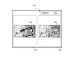
ところで、図6、或いは図7において、ユーザが「ディスプレイ」アイコンを選択した場合、メモリ(制御部110のRAM)に展開されている通話相手先から受信した画像データの複製を作成してメモリ(制御部110のRAM)に展開する。また、表示制御手段114が表示画面を図8に示すように2分割し、第1の表示領域を自局画像データ領域810とし、第2の表示領域を相手局画像データ領域820とする。自局画像データ領域810には編集中の画像データ422が表示され、相手局画像データ領域820には通話相手先から受信した画像データが表示される。
By the way, in FIG. 6 or FIG. 7, when the user selects the “display” icon, a copy of the image data received from the other party in the memory (RAM of the control unit 110) is created and stored in the memory ( The data is expanded in the RAM of the
なお、図8に示す表示画面においては上方に、「切替表示」アイコン、「戻る」アイコンから構成されるメニューアイコン830が設けられ、ユーザが「切替表示」アイコンを選択すると自局画像データ領域810、又は相手局画像データ領域が全画面表示される。この「切替表示」アイコンを選択操作する度に、自局画像データ領域810と相手局画像データ領域820からなる分割表示画面、自局画像データ領域810の全画面表示、相手局画像データ領域820の全画面表示を切替えて表示するようにしてもよい。
In the display screen shown in FIG. 8, a
また、図5〜図7において、ユーザが「保存」アイコン513を選択操作した場合、データ制御手段116は、メモリ(制御部110のRAM)に展開されている画像データを、メモリ170に保存する。ユーザが「印刷」アイコン514を選択操作した場合、データ制御手段116は、メモリ(制御部110のRAM)に展開されている画像を、テレビ電話装置100に接続されているプリンタへ出力し、印刷を行う。
5 to 7, when the user selects and operates the “save”
上記に説明した通り、本発明は、通話相手先から受信した画像データを編集・加工でき、編集・加工された画像データをさらに通話相手先に送信することができる。一方、通話相手先においても受信した画像データをさらに編集・加工して返信することができる。これにより、通話を行いながら、互いが画像データを送信し合うことで、画像データを共有することが可能となる。これらの画像データをもとに、意思の疎通を図り、より明確で誤りの少ない会話を行うことが可能となる。 As described above, according to the present invention, the image data received from the call partner can be edited and processed, and the edited and processed image data can be further transmitted to the call partner. On the other hand, the received image data can be further edited / processed and returned at the other party. Thereby, it is possible to share image data by transmitting image data to each other while making a call. Based on these image data, it is possible to communicate more clearly and to have a clearer conversation with less errors.
上記においては、画像データとして地図画像を例示した。地図のようなデータは、互いが同じ地図を見ているとしても口頭のみで情報を伝えたとしても誤解が生じやすい。本発明によれば、そのような誤解を防ぎ、より正確に情報を共有することが可能となる。 In the above, the map image was illustrated as image data. Data such as maps are likely to be misunderstood, even if each other sees the same map, even if information is conveyed verbally. According to the present invention, such misunderstanding can be prevented and information can be shared more accurately.
また、医療現場等において、通話者相互がX線写真のような画像データを見ながらそこに書き加えてゆくことで口頭よりもより正確に情報を提供することが可能となる。 In addition, in a medical field or the like, information can be provided more accurately than verbally by allowing callers to add to each other while viewing image data such as an X-ray photograph.
100 テレビ電話装置
101 有線LAN
102 IP電話ルータ
103 ブロードバンドルータ
104 ゲートウェイ
105 IP電話網
106 インターネット
107 PSTN網
108 加入者電話機
110 制御部
111 通信制御手段
112 音声信号処理手段
113 画像・映像信号処理手段
114 表示制御手段
115 画像編集手段
116 データ制御手段
117 時刻制御手段
120 マイク
130 スピーカ
140 カメラ
150 表示部
160 入力部
170 メモリ
100
DESCRIPTION OF
Claims (5)
通信回線における送受信の制御を行う通信制御手段、前記マイクから入力された音声を、通信回線送信用のデータ形式に変換するとともに前記通信回線から受信した音声信号を変換して前記スピーカに出力する音声信号処理手段、画像データ及び/又は前記カメラにおいて撮像された映像を、通信回線送信用のデータ形式に変換するとともに前記通信回線から受信した画像データ及び/又は映像信号を変換して表示制御手段に出力する画像・映像信号処理手段、前記映像信号と前記画像データを前記表示部に表示可能な態様に変換して前記表示部に表示する表示制御手段、前記画像データを、前記入力部からの指示に基づいて編集する画像編集手段、を有する制御部と、を備えるテレビ電話装置であって、
前記通話相手先から通信回線を介して受信した画像データを、前記画像編集手段が前記入力部からの指示に基づいて編集することを特徴とするテレビ電話装置。 A display unit, an input unit, a microphone, a speaker, a camera,
Communication control means for controlling transmission / reception in a communication line, audio that is input from the microphone and converted into a data format for communication line transmission, and audio that is received from the communication line and output to the speaker Signal processing means, image data and / or video captured by the camera are converted into a data format for communication line transmission, and image data and / or video signals received from the communication line are converted into display control means. Image / video signal processing means for outputting, display control means for converting the video signal and the image data into a form that can be displayed on the display section and displaying the display section on the display section, and instructions for the image data from the input section A video telephone device comprising: a control unit having an image editing means for editing based on
The video telephone apparatus, wherein the image editing means edits image data received from the call partner via a communication line based on an instruction from the input unit.
Priority Applications (1)
| Application Number | Priority Date | Filing Date | Title |
|---|---|---|---|
| JP2010292266A JP2012142679A (en) | 2010-12-28 | 2010-12-28 | Video telephone apparatus |
Applications Claiming Priority (1)
| Application Number | Priority Date | Filing Date | Title |
|---|---|---|---|
| JP2010292266A JP2012142679A (en) | 2010-12-28 | 2010-12-28 | Video telephone apparatus |
Publications (1)
| Publication Number | Publication Date |
|---|---|
| JP2012142679A true JP2012142679A (en) | 2012-07-26 |
Family
ID=46678550
Family Applications (1)
| Application Number | Title | Priority Date | Filing Date |
|---|---|---|---|
| JP2010292266A Pending JP2012142679A (en) | 2010-12-28 | 2010-12-28 | Video telephone apparatus |
Country Status (1)
| Country | Link |
|---|---|
| JP (1) | JP2012142679A (en) |
Cited By (15)
| Publication number | Priority date | Publication date | Assignee | Title |
|---|---|---|---|---|
| JP2015041977A (en) * | 2013-08-23 | 2015-03-02 | 株式会社ファインウェル | Transmitter receiver or receiver |
| JP2017200236A (en) * | 2017-07-11 | 2017-11-02 | 京セラ株式会社 | Portable electronic apparatus |
| US9980024B2 (en) | 2011-02-25 | 2018-05-22 | Rohm Co., Ltd. | Hearing system and finger ring for the hearing system |
| US10013862B2 (en) | 2014-08-20 | 2018-07-03 | Rohm Co., Ltd. | Watching system, watching detection device, and watching notification device |
| KR20180081827A (en) * | 2013-08-23 | 2018-07-17 | 로무 가부시키가이샤 | Portable telephone |
| US10079925B2 (en) | 2012-01-20 | 2018-09-18 | Rohm Co., Ltd. | Mobile telephone |
| US10103766B2 (en) | 2013-10-24 | 2018-10-16 | Rohm Co., Ltd. | Wristband-type handset and wristband-type alerting device |
| US10158947B2 (en) | 2012-01-20 | 2018-12-18 | Rohm Co., Ltd. | Mobile telephone utilizing cartilage conduction |
| US10356231B2 (en) | 2014-12-18 | 2019-07-16 | Finewell Co., Ltd. | Cartilage conduction hearing device using an electromagnetic vibration unit, and electromagnetic vibration unit |
| US10779075B2 (en) | 2010-12-27 | 2020-09-15 | Finewell Co., Ltd. | Incoming/outgoing-talk unit and incoming-talk unit |
| US10778824B2 (en) | 2016-01-19 | 2020-09-15 | Finewell Co., Ltd. | Pen-type handset |
| US10795321B2 (en) | 2015-09-16 | 2020-10-06 | Finewell Co., Ltd. | Wrist watch with hearing function |
| US10967521B2 (en) | 2015-07-15 | 2021-04-06 | Finewell Co., Ltd. | Robot and robot system |
| WO2022202353A1 (en) * | 2021-03-22 | 2022-09-29 | 株式会社アルファオメガ | Program, method, and information processing device |
| US11526033B2 (en) | 2018-09-28 | 2022-12-13 | Finewell Co., Ltd. | Hearing device |
Citations (2)
| Publication number | Priority date | Publication date | Assignee | Title |
|---|---|---|---|---|
| JPH05344498A (en) * | 1992-06-09 | 1993-12-24 | Sharp Corp | Video conference equipment |
| JP2004282481A (en) * | 2003-03-17 | 2004-10-07 | Seiko Epson Corp | Image editing program, method and device |
-
2010
- 2010-12-28 JP JP2010292266A patent/JP2012142679A/en active Pending
Patent Citations (2)
| Publication number | Priority date | Publication date | Assignee | Title |
|---|---|---|---|---|
| JPH05344498A (en) * | 1992-06-09 | 1993-12-24 | Sharp Corp | Video conference equipment |
| JP2004282481A (en) * | 2003-03-17 | 2004-10-07 | Seiko Epson Corp | Image editing program, method and device |
Cited By (24)
| Publication number | Priority date | Publication date | Assignee | Title |
|---|---|---|---|---|
| US10779075B2 (en) | 2010-12-27 | 2020-09-15 | Finewell Co., Ltd. | Incoming/outgoing-talk unit and incoming-talk unit |
| US9980024B2 (en) | 2011-02-25 | 2018-05-22 | Rohm Co., Ltd. | Hearing system and finger ring for the hearing system |
| US10079925B2 (en) | 2012-01-20 | 2018-09-18 | Rohm Co., Ltd. | Mobile telephone |
| US10778823B2 (en) | 2012-01-20 | 2020-09-15 | Finewell Co., Ltd. | Mobile telephone and cartilage-conduction vibration source device |
| US10158947B2 (en) | 2012-01-20 | 2018-12-18 | Rohm Co., Ltd. | Mobile telephone utilizing cartilage conduction |
| US10834506B2 (en) | 2012-06-29 | 2020-11-10 | Finewell Co., Ltd. | Stereo earphone |
| US10506343B2 (en) | 2012-06-29 | 2019-12-10 | Finewell Co., Ltd. | Earphone having vibration conductor which conducts vibration, and stereo earphone including the same |
| JP2015041977A (en) * | 2013-08-23 | 2015-03-02 | 株式会社ファインウェル | Transmitter receiver or receiver |
| US10237382B2 (en) | 2013-08-23 | 2019-03-19 | Finewell Co., Ltd. | Mobile telephone |
| US10075574B2 (en) | 2013-08-23 | 2018-09-11 | Rohm Co., Ltd. | Mobile telephone |
| KR101972290B1 (en) * | 2013-08-23 | 2019-04-24 | 파인웰 씨오., 엘티디 | Portable telephone |
| KR20180081827A (en) * | 2013-08-23 | 2018-07-17 | 로무 가부시키가이샤 | Portable telephone |
| US10103766B2 (en) | 2013-10-24 | 2018-10-16 | Rohm Co., Ltd. | Wristband-type handset and wristband-type alerting device |
| US10013862B2 (en) | 2014-08-20 | 2018-07-03 | Rohm Co., Ltd. | Watching system, watching detection device, and watching notification device |
| US10380864B2 (en) | 2014-08-20 | 2019-08-13 | Finewell Co., Ltd. | Watching system, watching detection device, and watching notification device |
| US10356231B2 (en) | 2014-12-18 | 2019-07-16 | Finewell Co., Ltd. | Cartilage conduction hearing device using an electromagnetic vibration unit, and electromagnetic vibration unit |
| US10848607B2 (en) | 2014-12-18 | 2020-11-24 | Finewell Co., Ltd. | Cycling hearing device and bicycle system |
| US11601538B2 (en) | 2014-12-18 | 2023-03-07 | Finewell Co., Ltd. | Headset having right- and left-ear sound output units with through-holes formed therein |
| US10967521B2 (en) | 2015-07-15 | 2021-04-06 | Finewell Co., Ltd. | Robot and robot system |
| US10795321B2 (en) | 2015-09-16 | 2020-10-06 | Finewell Co., Ltd. | Wrist watch with hearing function |
| US10778824B2 (en) | 2016-01-19 | 2020-09-15 | Finewell Co., Ltd. | Pen-type handset |
| JP2017200236A (en) * | 2017-07-11 | 2017-11-02 | 京セラ株式会社 | Portable electronic apparatus |
| US11526033B2 (en) | 2018-09-28 | 2022-12-13 | Finewell Co., Ltd. | Hearing device |
| WO2022202353A1 (en) * | 2021-03-22 | 2022-09-29 | 株式会社アルファオメガ | Program, method, and information processing device |
Similar Documents
| Publication | Publication Date | Title |
|---|---|---|
| JP2012142679A (en) | Video telephone apparatus | |
| WO2013080702A1 (en) | Video-phone device | |
| KR101880656B1 (en) | Mobile device, display apparatus and control method thereof | |
| US20050208962A1 (en) | Mobile phone, multimedia chatting system and method thereof | |
| KR20090022137A (en) | A mobile communication terminal having multilateral image communication function and multilateral method for converting image communication mode thereof | |
| CN101291413A (en) | Visual communication system and its main apparatus | |
| JP5396789B2 (en) | Telephone system | |
| JP2002044285A (en) | Mobile communication terminal device and portable display terminal device | |
| KR100499769B1 (en) | Method for displaying of pictures through instant messenger in mobile communication terminal and mobile communication terminal therefor | |
| JP2005168012A (en) | Video phone compatible type internet phone | |
| JP2002077840A (en) | Communication terminal | |
| WO2012088789A1 (en) | Method for transmitting information in visual telephone and communication terminal thereof | |
| JP5187890B2 (en) | Terminal, program and method for preferential control of transmission / reception of media data | |
| US20020080092A1 (en) | Method for transmitting information | |
| JP2013201593A (en) | Communication terminal apparatus | |
| US20090209292A1 (en) | Image display system, terminal device, image display method and program | |
| JP3982059B2 (en) | Data processing method for videophone device and videophone device | |
| JP4898603B2 (en) | Communication apparatus and communication method | |
| JP2010245767A (en) | Telephone device | |
| JP2009171272A (en) | Video telephone terminal device | |
| JP3892574B2 (en) | Line connection device in complex network | |
| JP2013090283A (en) | Videophone equipment | |
| JP2006100968A (en) | Communication terminal device with speaker notifying function and speaker notifying method | |
| JP2013070171A (en) | Television telephone apparatus | |
| JP2013201594A (en) | Communication terminal apparatus |
Legal Events
| Date | Code | Title | Description |
|---|---|---|---|
| A711 | Notification of change in applicant |
Free format text: JAPANESE INTERMEDIATE CODE: A712 Effective date: 20120522 |
|
| A621 | Written request for application examination |
Free format text: JAPANESE INTERMEDIATE CODE: A621 Effective date: 20131202 |
|
| RD01 | Notification of change of attorney |
Free format text: JAPANESE INTERMEDIATE CODE: A7421 Effective date: 20140128 |
|
| A977 | Report on retrieval |
Free format text: JAPANESE INTERMEDIATE CODE: A971007 Effective date: 20140916 |
|
| A02 | Decision of refusal |
Free format text: JAPANESE INTERMEDIATE CODE: A02 Effective date: 20150331 |