JP2012141532A - Active noise reduction device - Google Patents
Active noise reduction device Download PDFInfo
- Publication number
- JP2012141532A JP2012141532A JP2011001001A JP2011001001A JP2012141532A JP 2012141532 A JP2012141532 A JP 2012141532A JP 2011001001 A JP2011001001 A JP 2011001001A JP 2011001001 A JP2011001001 A JP 2011001001A JP 2012141532 A JP2012141532 A JP 2012141532A
- Authority
- JP
- Japan
- Prior art keywords
- transfer characteristic
- value
- step size
- noise reduction
- sound
- Prior art date
- Legal status (The legal status is an assumption and is not a legal conclusion. Google has not performed a legal analysis and makes no representation as to the accuracy of the status listed.)
- Pending
Links
Images


Abstract
Description
本発明は、不快な騒音に対し、逆位相且つ等振幅の信号を干渉させることでこの騒音を低減する能動騒音低減装置に関するもので、特に使用される場所の環境変化が比較的大きく、それに伴い音場特性が変化する自動車室内などの騒音を制御対象とする場合に関するものである。 The present invention relates to an active noise reduction device that reduces noise by causing signals having opposite phases and equal amplitudes to interfere with unpleasant noise. The present invention relates to a case where noise in a car interior or the like in which sound field characteristics change is controlled.
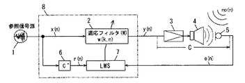
従来の能動騒音低減装置は、適応フィルタの係数更新アルゴリズムとしてフィルタードX−LMSアルゴリズムを用いるものが最も一般的である(例えば、非特許文献1または非特許文献2参照)。図13は、一般的なフィルタードX−LMSアルゴリズムを用いた能動騒音低減装置の構成を示すものである。図中、nは離散時間処理で動作し、騒音低減のための信号(2次騒音信号y)を発生するディジタル信号処理装置であるDSP(Digital Signal Processor)8のサンプリング周期Ts(sec)毎のサンプリングナンバーを表している。フィルタードX−LMSアルゴリズムによりTs(sec)毎に値が更新されるN個のフィルタ係数w(k)、(k=1,2,3,・・・,N)からなるFIR(Finite Impulse Response)型の適応フィルタ2に入力される信号xは参照信号と呼ばれ、その出力源である参照信号源1は、例えば本能動騒音低減装置を自動車の車室内騒音の低減に適用する場合、車両のシャーシに設置された加速度ピックアップ等である。なお、この参照信号xは、制御対象となる騒音noと相関が高い必要があり、相関が低い帯域の騒音は騒音低減効果が期待できない。適応フィルタ2でフィルタリング演算(畳み込み演算)された参照信号xは、2次騒音信号yとして2次騒音発生手段としての電力増幅器3とスピーカ4に送られ、騒音noを低減させる2次騒音として空間中に放射される。空間中で2次騒音と騒音noとが干渉した結果は、マイクロフォン5で残留音eとして検出され、適応フィルタ2のフィルタ係数w(k)を更新するLMSアルゴリズム演算部7に入力される。ここで、電力増幅器3の入力からマイクロフォン5の出力までの間の周波数領域での音響伝達特性をCとする。模擬音響伝達特性6は、音響伝達特性Cを模擬した周波数領域での特性C^を有している。この模擬音響伝達特性6は、一般的に適応フィルタ2と同様にNc個のフィルタ係数c^(m)、(m=1,2,・・・,Nc)からなるFIR型のフィルタで構成される。LMSアルゴリズム演算部7には、前記の残留音eに加え、さらに参照信号xを模擬音響伝達特性6でフィルタリング演算した信号rが入力される。この信号rは濾波参照信号と呼ばれ、フィルタードXの名称はこのことに由来する。さて、今、時刻nTs(sec)における各信号を考えることにする。適応フィルタ2のN個のフィルタ係数w(k)をベクトルで表現すると、
A conventional active noise reduction apparatus is most commonly one that uses a filtered X-LMS algorithm as a coefficient update algorithm for an adaptive filter (see, for example, Non-Patent

となる。ここで、Tは転置を意味する。同じく、周波数領域での音響伝達特性Cを模擬した特性C^を有する模擬音響伝達特性6のNc個のフィルタ係数c^(m)と、現時刻から(Nc−1)サンプル過去までのNc個の参照信号xをベクトルで表現すると、
It becomes. Here, T means transposition. Similarly, Nc filter coefficients c ^ (m) of the simulated
となる。模擬音響伝達特性6のフィルタ係数c^(m)は固定値であり、時不変である。このとき、現時刻での濾波参照信号rは、
It becomes. The filter coefficient c ^ (m) of the simulated
のように、式(2)で表現されたフィルタ係数c^(m)のベクトルと式(3)で表現された参照信号xのベクトルの行列演算で求めることができる。式(4)で求めた現時刻での濾波参照信号rと同様に、現時刻から(N−1)サンプル過去までのN個の濾波参照信号をベクトルで表現すると、 As described above, it can be obtained by matrix calculation of the vector of the filter coefficient c ^ (m) expressed by the equation (2) and the vector of the reference signal x expressed by the equation (3). Similarly to the filtered reference signal r at the current time obtained by the equation (4), N filtered reference signals from the current time to the past (N−1) samples are expressed by vectors.
となる。この濾波参照信号rのベクトルと現時刻の残留音eを用いて、次式のフィルタードX−LMSアルゴリズム It becomes. Using this filtered reference signal r vector and the residual sound e at the current time, the following filtered X-LMS algorithm
![]()
![]()
に基づき適応フィルタ2のフィルタ係数w(k)を更新していく。ここで、μはステップサイズパラメータと呼ばれる係数である。このステップサイズパラメータμは適応フィルタの1回あたりの更新量(つまり、収束速度)を調整するパラメータであるとともに、適応動作の安定性を決定付ける重要なパラメータである。能動騒音低減装置は、式(6)に基づいてTs(sec)毎に再帰的に適応フィルタ2のフィルタ係数w(k)を更新することで、マイクロフォン5の位置で騒音noと逆位相且つ等振幅となる最適な2次騒音を求めることができ、騒音を低減することが可能となる。
Based on the above, the filter coefficient w (k) of the
ここで、フィルタードX−LMSアルゴリズムを用いた一般的な能動騒音装置の動作安定性について述べる。この能動騒音低減装置の適応フィルタ2のフィルタ係数w(k)が収束し、安定的な騒音低減動作を継続するためには2つの重要な条件が必要となる。1つは模擬音響伝達特性6(C^)が実際の音響伝達特性Cを充分に模擬しており誤差が少ないことである。もう1つは適応フィルタのフィルタ係数w(k)を更新する際のステップサイズパラメータμの値が大き過ぎず、適度な大きさを採ることである。具体的には、前者の条件に対して、前記非特許文献2では、適応フィルタ2のフィルタ係数w(k)が収束する必要条件として、実際の音響伝達特性Cとそれを模擬した模擬音響伝達特性6との間の位相誤差が±90(deg)以内という条件があることが述べられている。これは能動騒音低減装置を設計する際の一般的な条件として周知である。特に、参照信号がシヌソイダル(周期正弦波)信号の場合について、下記非特許文献3でこの条件が導き出されている。また、後者の条件に対しては、ステップサイズパラメータμの値は、0<μ<2/λmax(但し、λmaxは濾波参照信号rの自己相関行列の最大固有値)の範囲で設定される必要があることが下記非特許文献4で述べられている。これも上記同様、能動騒音低減装置を設計する際の一般的な条件としては周知である。しかしながら、このような指標はあるものの、ステップサイズパラメータμの値は一般的には2/λmaxよりも充分小さい値を採ることが多い。これは、騒音が想定される以上に大きくなり、これに伴って参照信号が大きくなった場合でも余裕を持って安定的な適応動作を継続するためである。さらには、音響伝達特性Cの利得が経年変化などで初期状態から上昇変動してしまった場合でも、余裕を持って安定的に適応動作を行わせるためである。音響伝達特性Cの利得が初期状態から上昇した場合、模擬音響伝達特性6との間に利得誤差が発生することになるが、これは結局ステップサイズパラメータμがこの利得誤差分だけ上昇したことと等価になるためである。そのため、音響伝達特性Cの利得の経年変化も考慮して、余裕を持ってステップサイズパラメータμを充分小さく設定しておく必要がある。以上に述べた2つの条件のうち1つでも満たさない場合、適応フィルタ2のフィルタ係数w(k)は収束することなく発散してしまい、能動騒音低減装置から大音量且つ異常な音が発生することとなる。このように、フィルタードX−LMSアルゴリズムを用いた能動騒音低減装置を設計する場合、充分に動作安定性を考慮する必要がある。経年変化により音響伝達特性Cの利得のみならず、当然位相も変動することを考慮し、音場が変動しても安定的に動作するように余裕を持った設計が必要となる。特にステップサイズパラメータμの値は、動作安定性を決定付けるため重要である。その値の決定には、細心の注意を払わなければならない。
Here, the operation stability of a general active noise device using the filtered X-LMS algorithm will be described. In order for the filter coefficient w (k) of the
しかしながら、前記従来の一般的なフィルタードX−LMSアルゴリズムを用いた能動騒音低減装置では、安定的に騒音低減動作を継続するための2つの条件は周知であるものの、それぞれが独立した形で存在しており、これら両者の相互関係については明確にされていなかった。従って、音響伝達特性の利得と位相がともに変動する場合に、適応フィルタのフィルタ係数が発散状態に至るまでの利得余裕と位相余裕をともに把握することは困難であった。そのため、動作安定性を決定付けるステップサイズパラメータμの値は余裕を持たせて充分小さい値に設定され、しかもその値は実験的または経験的に決定されていた。 However, in the conventional active noise reduction apparatus using the conventional filtered X-LMS algorithm, although two conditions for continuing the noise reduction operation stably are well known, each exists independently. However, the interrelationship between these two has not been clarified. Therefore, when both the gain and the phase of the acoustic transfer characteristic fluctuate, it is difficult to grasp both the gain margin and the phase margin until the filter coefficient of the adaptive filter reaches the divergence state. Therefore, the value of the step size parameter μ that determines the operation stability is set to a sufficiently small value with a margin, and the value is determined experimentally or empirically.
本発明は、前記従来の課題を解決するもので、環境の変化に伴って音響伝達特性が変動することを考慮し、適応フィルタのフィルタ係数が発散状態に至るまでの利得余裕と位相余裕をともに把握して数式に基づいて論理的にステップサイズパラメータの値を決定することで、音響伝達特性が初期状態から所定値変動した場合でも安定した動作を保証することができる能動騒音低減装置を提供することを目的とする。 The present invention solves the above-described conventional problems, and considers that the acoustic transfer characteristics fluctuate with changes in the environment, and provides both a gain margin and a phase margin until the filter coefficient of the adaptive filter reaches a divergence state. Provided is an active noise reduction device that can assure stable operation even when the acoustic transfer characteristics fluctuate by a predetermined value from the initial state by grasping and logically determining a step size parameter value based on a mathematical expression For the purpose.
本発明の能動騒音低減装置は、前記適応フィルタのサンプリング周波数と前記適応フィルタのフィルタ係数の個数によって決定される離散周波数毎に、前記模擬音響伝達特性の利得値及び位相値と、前記音響伝達特性の初期状態から所定値変動した音響伝達特性の利得値及び位相値と、前記参照信号をフーリエ変換して得られた値の実部の2乗と虚部の2乗の和の時間平均値を用いて下式を満たす前記ステップサイズパラメータを求め、そのうちの最小値を決定する決定部を有し、前記LMSアルゴリズム演算部は前記決定部が決定した前記ステップサイズパラメータを用いる。 The active noise reduction apparatus according to the present invention includes a gain value and a phase value of the simulated acoustic transfer characteristic, and the acoustic transfer characteristic for each discrete frequency determined by the sampling frequency of the adaptive filter and the number of filter coefficients of the adaptive filter. The time average value of the sum of the square of the real part and the square of the imaginary part of the value obtained by Fourier-transforming the reference signal, and the gain value and phase value of the acoustic transfer characteristic changed by a predetermined value from the initial state of The step size parameter satisfying the following expression is used to determine a minimum value of the step size parameter, and the LMS algorithm calculation unit uses the step size parameter determined by the determination unit.
(但し、μ:ステップサイズパラメータ、X:参照信号をフーリエ変換した値、|X|2:Xの実部の2乗と虚部の2乗の和、|X|2 ave:|X|2の時間平均値、Rc^:模擬音響伝達特性の利得値、θc^:模擬音響伝達特性の位相値、Rc’:初期状態の音響伝達特性から所定値変動した音響伝達特性の利得値、θc’:初期状態の音響伝達特性から所定値変動した音響伝達特性の位相値)
本構成によって、音響伝達特性が初期状態から所定値変動したときでも安定に動作できるステップサイズパラメータの値を論理的に決定することができる。
(Where μ: step size parameter, X: value obtained by Fourier transform of reference signal, | X | 2 : sum of square of real part and square of imaginary part, | X | 2 ave : | X | 2 Rc ^: Simulated sound transfer characteristic gain value, θc ^: Simulated sound transfer characteristic phase value, Rc ': Sound transfer characteristic gain value changed by a predetermined value from the initial state sound transfer characteristic, θc' : Phase value of the sound transfer characteristic that is changed by a predetermined value from the sound transfer characteristic in the initial state)
With this configuration, it is possible to logically determine the value of the step size parameter that can be stably operated even when the acoustic transfer characteristic varies by a predetermined value from the initial state.
本発明の能動騒音低減装置によれば、環境の変化に伴って音響伝達特性が変動することを考慮し、適応フィルタのフィルタ係数が発散状態に至るまでの利得余裕と位相余裕をともに把握して数式に基づいて論理的にステップサイズパラメータの値を決定することで、音響伝達特性が初期状態から所定値変動した場合でも安定した動作を保証することができる。 According to the active noise reduction device of the present invention, it is possible to grasp both the gain margin and the phase margin until the filter coefficient of the adaptive filter reaches the divergence state, considering that the acoustic transfer characteristics fluctuate with changes in the environment. By logically determining the value of the step size parameter based on the mathematical formula, it is possible to guarantee a stable operation even when the acoustic transfer characteristic varies by a predetermined value from the initial state.
以下本発明を実施するための最良の形態について、図面を参照しながら説明する。 The best mode for carrying out the present invention will be described below with reference to the drawings.
(実施の形態1)
図1は、本発明実施の形態1における能動騒音低減装置の図である。なお、図1において、背景技術において示した従来の能動騒音低減装置(図13)と同一の構成要素には同一の符号を付して、説明の省略を行う。図1において、図13との相違点であるDSP8内部の決定部9は、LMSアルゴリズム演算部7が用いるステップサイズパラメータμを決定する。このステップサイズパラメータμは、能動騒音低減装置が安定に動作するために、重要なパラメータである。ステップサイズパラメータμが大きいと、式(6)からもわかるように適応フィルタのフィルタ係数の更新速度が速くなり、騒音が時々刻々と変化する場合の追従性が向上するため、結果として騒音低減効果も向上する。しかし、あまり大き過ぎると動作安定性が悪くなってしまい、最悪の場合適応フィルタのフィルタ係数が発散してしまう。逆にステップサイズパラメータμが小さいと、動作は安定するものの騒音を低減するまでに時間を要し、騒音の変化に対する追従性も悪いため、騒音低減効果は劣化する。このようにフィルタードX−LMSアルゴリズムを用いた能動騒音低減装置の動作安定性と騒音低減効果はトレードオフにあるため、その値の決定は困難を伴う。一般的には、安定性がより重要視されるため、発散までの余裕を持たせて充分小さい値(例えば、0.0001など)に設定される。また、この値は実験的または経験的に決定される。このように決められたステップサイズパラメータμでは、能動騒音低減装置がどれほどの安定余裕度を持って動作しているのかが不明である。特に、先に述べたフィルタードX−LMSアルゴリズムを用いた能動騒音低減装置が安定に動作するための2つの重要な条件が作用するところの音響伝達特性Cと模擬音響伝達特性6(C^)との間の利得誤差と位相誤差に関しては、その余裕度は全くわからなかった。本発明の決定部9は、従来のこのようなステップサイズパラメータμの決定過程では考慮されていなかった実際の音響伝達特性の変動を考慮した、次式
(Embodiment 1)
FIG. 1 is a diagram of an active noise reduction apparatus according to
(但し、μ:ステップサイズパラメータ、X:参照信号をフーリエ変換した値、|X|2:Xの実部の2乗と虚部の2乗の和、|X|2 ave:|X|2の時間平均値、Rc^:模擬音響伝達特性の利得値、θc^:模擬音響伝達特性の位相値、Rc’:初期状態の音響伝達特性から所定値変動した音響伝達特性の利得値、θc’:初期状態の音響伝達特性から所定値変動した音響伝達特性の位相値)
に基づいてステップサイズパラメータμを決定する。
(Where μ: step size parameter, X: value obtained by Fourier transform of reference signal, | X | 2 : sum of square of real part and square of imaginary part, | X | 2 ave : | X | 2 Rc ^: Simulated sound transfer characteristic gain value, θc ^: Simulated sound transfer characteristic phase value, Rc ': Sound transfer characteristic gain value changed by a predetermined value from the initial state sound transfer characteristic, θc' : Phase value of the sound transfer characteristic that is changed by a predetermined value from the sound transfer characteristic in the initial state)
The step size parameter μ is determined based on
では、具体的に決定部9が式(7)に基づいてステップサイズパラメータμを決定する過程を説明していく。図1に示した能動騒音低減装置を動作させるためには、模擬音響伝達特性6のフィルタ係数c^を決定する必要がある。そのために、能動騒音低減装置とは別に用意した周波数応答解析器などの計測器(図示せず)を用いて、能動騒音低減装置が設置されている環境における現在の音響伝達特性Cを計測する必要がある。計測した結果、ここでは、図2に示すような周波数領域での特性(利得特性と位相特性)が得られたとする。能動騒音低減装置は、周波数領域の情報ではなく、時間領域の情報としてフィルタ係数c^を保持する必要があるため、周波数応答解析器の計測結果を逆フーリエ変換して時間領域の情報に変換したもの(インパルス応答)を模擬音響伝達特性6のフィルタ係数c^とする。図2の周波数特性を用い,インパルス応答の長さを256として求めた模擬音響伝達特性6のフィルタ係数c^を図3に示す。この模擬音響伝達特性6のフィルタ係数c^は、決定部9にも入力され、後述する式(7)に基づいてステップサイズパラメータμを決定する過程で使用される。一方、決定部9には、参照信号源1の信号も入力される。ここでは、決定部9に、図4に示すような時間領域での信号が入力されたとする。決定部9は、例えば、DSP8の内部に有しているメモリ(図示せず)に参照信号源1の信号を一定時間(例えば、10(sec))記録する。これも同じく、後述する式(7)に基づいてステップサイズパラメータμを決定する過程で使用される。
Now, the process in which the determining
ここで、能動騒音低減装置のサンプリング周波数fsは3000(Hz)、適応フィルタ2のフィルタ係数wの個数(インパルス応答の長さ)は、模擬音響伝達特性6のフィルタ係数c^と同じく256個とする。このとき、適応フィルタ2の周波数分解能は、3000/256=11.7188(Hz)であるため、離散周波数は、DC(0Hz)からナイキスト周波数である1500(Hz)までを11.7188(Hz)間隔で区切った値となる。以下では、その中の1つである、199.22(Hz)の場合を代表的に説明するが、他の離散周波数でも全く同様である。
Here, the sampling frequency fs of the active noise reduction device is 3000 (Hz), and the number of filter coefficients w of the adaptive filter 2 (the length of the impulse response) is 256, which is the same as the filter coefficient c ^ of the simulated
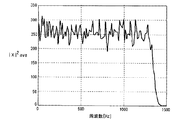
さて、決定部9は、上述した2つの入力を用い、式(7)に基づいてステップサイズパラメータμを決定する。ここでは、音響伝達特性の利得が現在の初期状態Cから+6(dB)上昇変動したときに、発散状態に至るまでに少なくとも+45(deg)の位相余裕があるように、つまり、変動後の音響伝達特性C’が現在の初期状態C(=C^)から利得が+6(dB)且つ位相が+45(deg)変動しても能動騒音低減装置が安定に動作することを保証するステップサイズパラメータμを決定していくことにする。まず、式(7)において、Rc^とθc^は模擬音響伝達特性6の利得特性と位相特性を表している。従って、199.22(Hz)における模擬音響伝達特性6の利得値と位相値を求め、その値を単に代入すればよい。しかし、決定部9に入力されている模擬音響伝達特性6のフィルタ係数c^は時間領域の情報であるため、決定部9はこれをフーリエ変換して周波数領域の情報に変換する必要がある。その結果は、図2に示した周波数領域での特性と一致する。図2より、199.22(Hz)における利得値は7.14(dB)、位相値は−48.33(deg)である。そこで、決定部9は、Rc^=10(7.14/20)=2.28、θc^=−48.33を式(7)に代入する。次に、式(7)において、Rc’とθc’は、初期状態の音響伝達特性Cから所定値変動した音響伝達特性C’の利得特性と位相特性を表している。ここでは、変動後の音響伝達特性C’が初期状態C(=C^)から利得が+6(dB)且つ位相が+45(deg)変動した特性であるため、Rc’=10((7.14+6.00)/20)=4.54、θc’=−48.33+45.00=−3.33である。そこで、決定部9は、これらを式(7)に代入する。さらに、式(7)において、|X|2 aveは参照信号をフーリエ変換した値の実部の2乗と虚部の2乗の和の時間平均値を表している。これを求めるために、まず、決定部9は、DSP8の内部のメモリに一定時間記録された参照信号を適応フィルタ2のフィルタ係数wの個数(ここでは、256)毎に区切って、それぞれにフーリエ変換を行い、各区間で離散周波数毎の|X|2を得る。そして、決定部9は、得られた|X|2を全区間に渡って平均化処理することで離散周波数毎の|X|2 aveを得る。決定部9が算出した|X|2 aveを図5に示す。199.22(Hz)において、|X|2 ave=274.4である。そこで、決定部9は、これを式(7)に代入する。以上より、199.22(Hz)において、音響伝達特性C’が初期状態Cから利得が+6(dB)且つ位相が+45(deg)変動しても能動騒音低減装置が安定に動作することを保証するステップサイズパラメータμの値は、0.00049より小さな値であると求まる。そこで、決定部9は、199.22(Hz)におけるステップサイズパラメータμとして、例えば、0.00048を決定する。
Now, the
さて、今度は視点を変えて、現在設定しているステップサイズパラメータμを用いて能動騒音低減装置を動作させた場合、それが安定に動作するために許容される音響伝達特性Cの利得変動と位相変動を考えてみる。式(7)を変形すると、 Now, when the viewpoint is changed and the active noise reduction apparatus is operated using the currently set step size parameter μ, the gain variation of the acoustic transfer characteristic C that is allowed to operate stably is changed. Consider phase fluctuations. When formula (7) is transformed,
が得られる。式(8)は、上記で決定されたステップサイズパラメータμによって制約される能動騒音低減装置の動作安定性の限界値に関して、視覚的に理解を手助けしてくれる。式(8)のμ、Rc^、|X|2 aveに上記の各値を代入し、横軸を音響伝達特性の初期状態からの利得変動値、つまりC’とC^の利得差として表した場合のグラフを図6に示す。図6において、縦軸は式(8)から求められた、各利得変動のときに許容される音響伝達特性の初期状態からの位相変動を表している。即ち、このグラフは、現在決定されているステップサイズパラメータを使用して能動騒音低減装置を動作させた場合に、一つの離散周波数(この場合、199.22(Hz))において、能動騒音低減装置が安定に動作することができる音響伝達特性の利得変動と位相変動の許容範囲(安定領域)を表している。このグラフの原点(音響伝達特性の利得変動が0(dB)、位相変動が0(deg))は、音響伝達特性が初期状態から変動していない場合(C’=C^、つまり、音響伝達特性Cを計測した直後に模擬音響伝達特性C^を求めた状態)を表している。グラフより、現在決定されているステップサイズパラメータμの値では、この状況においても、既に位相余裕は±90(deg)もなく、±69.3(deg)しかないことが読み取れる。さらに、同じく、現在決定されているステップサイズパラメータμの値では、音響伝達特性の位相特性が一切変化しなくとも、利得特性だけが+9.1(dB)以上変動するとき、即ちステップサイズパラメータμが現在値の0.00048より2.85(倍)大きくなると、安定領域を外れ、不安定になる(最悪の場合、発散状態に至る)ことも読み取れる。また、ここで決定したステップサイズパラメータμの値では、音響伝達特性の利得変動が+6(dB)の場合に許容される位相変動は、所望どおり±45(deg)となっていることも視覚的に容易に理解できる。 Is obtained. Equation (8) helps visually understand the limit value of the operational stability of the active noise reduction device constrained by the step size parameter μ determined above. Substituting each of the above values into μ, Rc ^, | X | 2 ave in Equation (8), the horizontal axis represents the gain fluctuation value from the initial state of the acoustic transfer characteristic, that is, the gain difference between C ′ and C ^. FIG. 6 shows a graph in the case of the above. In FIG. 6, the vertical axis represents the phase variation from the initial state of the acoustic transfer characteristic allowed from each gain variation, which is obtained from Equation (8). That is, this graph shows that the active noise reduction apparatus is operated at one discrete frequency (in this case, 199.22 (Hz)) when the active noise reduction apparatus is operated using the currently determined step size parameter. Represents the permissible range (stable region) of gain fluctuation and phase fluctuation of the acoustic transfer characteristic that can stably operate. The origin of this graph (acoustic transfer characteristic gain fluctuation is 0 (dB), phase fluctuation is 0 (deg)) is the case where the acoustic transmission characteristic has not changed from the initial state (C ′ = C ^, that is, acoustic transmission). This represents a state in which the simulated acoustic transfer characteristic C ^ is obtained immediately after measuring the characteristic C). From the graph, it can be seen that the step margin parameter μ currently determined has a phase margin of no more than ± 90 (deg) and only ± 69.3 (deg) even in this situation. Further, similarly, with the currently determined value of the step size parameter μ, even when the phase characteristic of the acoustic transfer characteristic does not change at all, only the gain characteristic varies by +9.1 (dB) or more, that is, the step size parameter μ. If the current value becomes 2.85 (times) larger than 0.00048 of the current value, it can be read that the stable region is not reached and becomes unstable (in the worst case, a divergent state is reached). It is also visually apparent that the phase variation allowed when the gain variation of the acoustic transfer characteristic is +6 (dB) is ± 45 (deg) as desired with the step size parameter μ determined here. Easy to understand.
ここでは離散周波数の1つである199.22(Hz)について述べたが、他の離散周波数でもステップサイズパラメータμの決定方法は同じである。その結果、離散周波数毎にステップサイズパラメータμが求まることになるが、決定部9はその中の最小値を選択する。そうすることで、全ての離散周波数の中で最も動作安定性に対してクリティカルな周波数帯域においても所望の音響伝達特性の変動余裕を有する能動騒音低減装置を実現することができ、システム全体としての動作安定性を保証することができる。
Here, 199.22 (Hz), which is one of the discrete frequencies, has been described, but the determination method of the step size parameter μ is the same for other discrete frequencies. As a result, the step size parameter μ is obtained for each discrete frequency, and the
では、シミュレーションを用いることで、式(7)、(8)の妥当性を検証する。なお、以下に説明するシミュレーションにおいては、決定部9が式(7)に基づいて求めた結果から、全ての離散周波数の中で最も動作安定性に対してクリティカルな周波数帯域は199.22(Hz)であることがわかっている。従って、特にこの周波数での動作安定性に注目して説明を行う。まず、図6に示したように、ステップサイズパラメータμを0.00048に設定したとき、音響伝達特性の利得変動が+6(dB)、位相変動が±45(deg)ある場合、能動騒音低減装置は安定に動作することができる。しかしながら、このときの動作点は安定領域と不安定領域の境界にあるので不安定になることはないとは言え、より確実な安定性が保証されているとき(より小さなステップサイズパラメータμが設定され、安定領域のより内部に動作点が存在するとき)と比較すると、騒音低減効果は幾らか劣ることが予想される。このときのシミュレーション結果(騒音のパワースペクトル密度)を図7に示す。能動騒音低減装置は、制御帯域である50(Hz)から500(Hz)で安定的に騒音を低減していることがわかる。199.22(Hz)においても10(dB)以上の騒音低減効果が得られている。しかし、その近傍の周波数と比較すると少し効果が劣化していることがわかる。これは、図6から想定されるとおりの結果である。次に、ステップサイズパラメータμを0.00055に設定した場合の安定領域のグラフを図8に示す。この場合、音響伝達特性の利得変動が+6(dB)、位相変動が±45(deg)あると(図中、●で動作点を示す)、動作点は安定領域を外れ、不安定領域に入ってしまう。このとき、能動騒音低減装置は、199.22(Hz)の騒音を低減できず、むしろ増音してしまうことが予想される。しかしながら、大きく安定領域を外れているわけではないので、発散に至ることはないとも予想される。このときのシミュレーション結果を図9に示す。能動騒音低減装置は、予想どおり、199.22(Hz)の騒音を低減できず、4(dB)程度増音していることがわかる。また、不安定ではあるものの、少しの増音だけで収まっており、システムとしては発散に至っていないこともわかる。さらに、ステップサイズパラメータμを0.001に設定した場合の安定領域のグラフを図10に示す。この場合、音響伝達特性の利得変動が+6(dB)、位相変動が±45(deg)あると、能動騒音低減装置の動作点は安定領域を大きく外れ、完全に不安定領域に入ってしまう。このとき、能動騒音低減装置は、199.22(Hz)から発散が始まり、それが引き金になり、システム全体で大きく増音してしまうことが予想される。このときのシミュレーション結果を図11に示す。能動騒音低減装置は、予想どおり、199.22(Hz)を中心に発散し、システム全体で大きく増音していることがわかる。
Then, the validity of Expressions (7) and (8) is verified by using simulation. In the simulation described below, from the result obtained by the
以上のように、本実施の形態1に示す能動騒音低減装置は、適応フィルタのフィルタ係数が発散状態に至るまでの利得余裕と位相余裕をともに把握して、式(7)を用いて論理的に求められた離散周波数毎の最適なステップサイズパラメータμの中から最小値を選択することで、音響伝達特性が初期状態から所定値変動した場合でも安定した動作を保証することができるという効果を奏する。 As described above, the active noise reduction apparatus shown in the first embodiment grasps both the gain margin and the phase margin until the filter coefficient of the adaptive filter reaches the divergence state, and logically uses the equation (7). By selecting the minimum value from the optimum step size parameter μ for each discrete frequency determined in step (b), it is possible to ensure stable operation even when the acoustic transfer characteristics fluctuate by a predetermined value from the initial state. Play.
(実施の形態2)
以下、実施の形態2を用いて、本発明の請求項2に記載の発明について説明する。本実施の形態は図1に示した上記実施の形態1と同じ構成からなり、決定部9がステップサイズパラメータμを決定するタイミングに関するものである。上記の実施の形態1で述べたように、模擬音響伝達特性6の特性C^は、音響伝達特性の初期状態(C)を充分に模擬している必要がある。その上で式(7)を計算しないと、音響伝達特性が初期状態から所定値変動した場合に安定した動作を保証するステップサイズパラメータμの値を正確に決定できなくなる。従って、模擬音響伝達特性6の特性を決定直後にステップサイズパラメータμの値を決定するものとする。
(Embodiment 2)
Hereinafter, the second aspect of the present invention will be described with reference to the second embodiment. This embodiment has the same configuration as that of the first embodiment shown in FIG. 1 and relates to the timing at which the
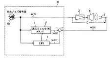
では、模擬音響伝達特性6の特性を決定する方法について、図12を用いて具体的に説明する。図12において、基本的な構成は図1に示したものと同様であり、同一の符号を付して説明を省略する。DSP8内の構成をプログラムで図12のように変更することにより、音響伝達特性Cを求める。この方法は、一般的には適応フィルタを用いたシステム同定と言われており、未知の系を適応処理で求めるために広く知られた手法である。能動騒音低減装置は、もともと適応フィルタ2を内蔵しているため、少しのプログラム変更でこの同定動作を行うことができる。過程としては、まず、白色ノイズ信号源10から一様なスペクトルを有する白色ノイズ信号wxを発生させ、電力増幅器3を通じてスピーカ4から放射する。適応フィルタ2には同じく白色ノイズ信号wxが入力される。適応フィルタ2でフィルタリング演算した出力wyとマイクロフォン5からの出力信号であるwdが等しくなるように、即ち誤差we=wd−wyが最小になるようにLMSアルゴリズム演算部7が適応フィルタ2のフィルタ係数w(k)を更新する。その更新式は、式(6)と同様に、
Now, a method for determining the characteristic of the simulated acoustic transfer characteristic 6 will be specifically described with reference to FIG. In FIG. 12, the basic configuration is the same as that shown in FIG. The acoustic transfer characteristic C is obtained by changing the configuration in the
![]()
![]()
である。ただし、符号が異なることに注意が必要である。ここで、μはステップサイズパラメータであり、同定の際の値としては非常に小さな値(例えば、0.0001など)が採られる。これは、時間を要しても正確に同定を行わせるためである。また、式(6)では濾波参照信号のベクトルであった箇所が、白色ノイズ信号のベクトルになっていることは容易に理解される。このようにして模擬音響伝達特性6の特性を求めた直後に、決定部9が前記実施の形態1の手順に従って、ステップサイズパラメータμを決定することで、より実際の状況に即した正確な設計を行うことができる。
It is. However, it should be noted that the signs are different. Here, μ is a step size parameter, and a very small value (for example, 0.0001) is adopted as a value at the time of identification. This is to allow accurate identification even if time is required. Further, it can be easily understood that the portion that was the vector of the filtered reference signal in Equation (6) is the vector of the white noise signal. Immediately after obtaining the characteristics of the simulated acoustic transfer characteristic 6 in this way, the
以上のように、本実施の形態2に示す能動騒音低減装置は、模擬音響伝達特性6の特性を決定直後にステップサイズパラメータμの値を決定することで、音響伝達特性が初期状態から所定値変動した場合に安定した動作を保証するステップサイズパラメータμの値をより正確に求めることができるという効果を奏する。 As described above, the active noise reduction apparatus shown in the second embodiment determines the value of the step size parameter μ immediately after determining the characteristic of the simulated sound transfer characteristic 6 so that the sound transfer characteristic is a predetermined value from the initial state. There is an effect that the value of the step size parameter μ that guarantees a stable operation when it fluctuates can be obtained more accurately.
本発明にかかる能動騒音低減装置は、適応フィルタのフィルタ係数が発散状態に至るまでの利得余裕と位相余裕をともに把握して数式に基づいて論理的にステップサイズパラメータの値を決定することで、音響伝達特性が初期状態から所定値変動した場合でも安定した動作を保証することが可能になるので、使用される場所の環境変化が比較的大きく、それに伴い音場特性が変化する自動車室内などの騒音を制御対象とする場合に有用である。 The active noise reduction device according to the present invention grasps both the gain margin and the phase margin until the filter coefficient of the adaptive filter reaches the divergence state, and logically determines the value of the step size parameter based on the formula, Even if the acoustic transfer characteristics fluctuate by a predetermined value from the initial state, it is possible to guarantee stable operation, so the environmental change of the place where it is used is relatively large and the sound field characteristics change accordingly. This is useful when noise is to be controlled.
1 参照信号源
2 適応フィルタ
3 電力増幅器(2次騒音発生手段)
4 スピーカ(2次騒音発生手段)
5 マイクロフォン
6 模擬音響伝達特性
7 LMSアルゴリズム演算部
8 DSP
9 決定部
10 白色ノイズ信号源
1
4 Speaker (secondary noise generating means)
5
9 Determining
Claims (2)
前記適応フィルタのサンプリング周波数と前記適応フィルタのフィルタ係数の個数によって決定される離散周波数毎に、前記模擬音響伝達特性の利得値及び位相値と、前記音響伝達特性の初期状態から所定値変動した音響伝達特性の利得値及び位相値と、前記参照信号をフーリエ変換して得られた値の実部の2乗と虚部の2乗の和の時間平均値を用いて下式を満たす前記ステップサイズパラメータを求め、そのうちの最小値を決定する決定部を有し、前記LMSアルゴリズム演算部は前記決定部が決定した前記ステップサイズパラメータを用いることを特徴とする能動騒音低減装置。
For each discrete frequency determined by the sampling frequency of the adaptive filter and the number of filter coefficients of the adaptive filter, a gain value and a phase value of the simulated acoustic transfer characteristic, and a sound that varies by a predetermined value from the initial state of the acoustic transfer characteristic The step size satisfying the following expression using a gain value and a phase value of a transfer characteristic and a time average value of a sum of a square of a real part and a square of an imaginary part of a value obtained by Fourier transforming the reference signal An active noise reduction apparatus comprising: a determination unit that obtains parameters and determines a minimum value of the parameters; and the LMS algorithm calculation unit uses the step size parameter determined by the determination unit.
Priority Applications (1)
| Application Number | Priority Date | Filing Date | Title |
|---|---|---|---|
| JP2011001001A JP2012141532A (en) | 2011-01-06 | 2011-01-06 | Active noise reduction device |
Applications Claiming Priority (1)
| Application Number | Priority Date | Filing Date | Title |
|---|---|---|---|
| JP2011001001A JP2012141532A (en) | 2011-01-06 | 2011-01-06 | Active noise reduction device |
Publications (1)
| Publication Number | Publication Date |
|---|---|
| JP2012141532A true JP2012141532A (en) | 2012-07-26 |
Family
ID=46677863
Family Applications (1)
| Application Number | Title | Priority Date | Filing Date |
|---|---|---|---|
| JP2011001001A Pending JP2012141532A (en) | 2011-01-06 | 2011-01-06 | Active noise reduction device |
Country Status (1)
| Country | Link |
|---|---|
| JP (1) | JP2012141532A (en) |
Cited By (2)
| Publication number | Priority date | Publication date | Assignee | Title |
|---|---|---|---|---|
| JP2014174349A (en) * | 2013-03-08 | 2014-09-22 | Toshiba Corp | Active silencer and active silencing method |
| CN104993877A (en) * | 2014-04-16 | 2015-10-21 | 百富计算机技术(深圳)有限公司 | Anti-interference method and apparatus |
-
2011
- 2011-01-06 JP JP2011001001A patent/JP2012141532A/en active Pending
Cited By (2)
| Publication number | Priority date | Publication date | Assignee | Title |
|---|---|---|---|---|
| JP2014174349A (en) * | 2013-03-08 | 2014-09-22 | Toshiba Corp | Active silencer and active silencing method |
| CN104993877A (en) * | 2014-04-16 | 2015-10-21 | 百富计算机技术(深圳)有限公司 | Anti-interference method and apparatus |
Similar Documents
| Publication | Publication Date | Title |
|---|---|---|
| Wu et al. | A simplified adaptive feedback active noise control system | |
| US9363599B2 (en) | Systems and methods for protecting a speaker | |
| Aslam et al. | A new adaptive strategy to improve online secondary path modeling in active noise control systems using fractional signal processing approach | |
| JP6429174B2 (en) | Signal processing device, program, range hood device, and frequency bin selection method in signal processing device | |
| Rees et al. | Adaptive algorithms for active sound-profiling | |
| US10229666B2 (en) | Signal processing device, program, and range hood device | |
| JP2008197284A (en) | Filter coefficient calculation device, filter coefficient calculation method, control program, computer-readable recording medium, and audio signal processing apparatus | |
| TW201804816A (en) | Method, system for self-tuning active noise cancellation and headset apparatus | |
| JPWO2017006547A1 (en) | Active noise reduction device | |
| Wu et al. | An improved active noise control algorithm without secondary path identification based on the frequency-domain subband architecture | |
| JP2008192136A (en) | Apparatus and method for optimally estimating transducer parameters | |
| EP2284833A1 (en) | A method for monitoring the influence of ambient noise on an adaptive filter for acoustic feedback cancellation | |
| Rout et al. | PSO based adaptive narrowband ANC algorithm without the use of synchronization signal and secondary path estimate | |
| JP2012123135A (en) | Active noise reduction device | |
| Guldenschuh et al. | Detection of secondary-path irregularities in active noise control headphones | |
| JP2012141532A (en) | Active noise reduction device | |
| Lasota et al. | Iterative learning approach to active noise control of highly autocorrelated signals with applications to machinery noise | |
| JP4690243B2 (en) | Digital filter, periodic noise reduction device, and noise reduction device | |
| Guldenschuh | Secondary-path models in adaptive-noise-control headphones | |
| WO2023040025A1 (en) | Feedback-type active noise control system and method based on secondary channel online identification | |
| Wesselink et al. | Fast affine projections and the regularized modified filtered-error algorithm in multichannel active noise control | |
| Landau et al. | Active noise control: Adaptive vs. robust approach | |
| JP6304643B2 (en) | Nonlinear distortion reduction apparatus, method, and program for speaker | |
| Chang et al. | Enhanced offline secondary path modeling method for narrowband active noise control system | |
| JP6116300B2 (en) | Active silencer system |