JP2012141013A - Valve chamber casing - Google Patents
Valve chamber casing Download PDFInfo
- Publication number
- JP2012141013A JP2012141013A JP2010294202A JP2010294202A JP2012141013A JP 2012141013 A JP2012141013 A JP 2012141013A JP 2010294202 A JP2010294202 A JP 2010294202A JP 2010294202 A JP2010294202 A JP 2010294202A JP 2012141013 A JP2012141013 A JP 2012141013A
- Authority
- JP
- Japan
- Prior art keywords
- valve chamber
- chamber casing
- casing
- peripheral surface
- inner valve
- Prior art date
- Legal status (The legal status is an assumption and is not a legal conclusion. Google has not performed a legal analysis and makes no representation as to the accuracy of the status listed.)
- Granted
Links
- 230000002093 peripheral effect Effects 0.000 claims abstract description 44
- 239000012530 fluid Substances 0.000 claims abstract description 11
- 239000011810 insulating material Substances 0.000 claims description 4
- 239000000463 material Substances 0.000 abstract description 17
- 229910001208 Crucible steel Inorganic materials 0.000 description 15
- 230000000630 rising effect Effects 0.000 description 11
- 230000000694 effects Effects 0.000 description 10
- 230000005855 radiation Effects 0.000 description 7
- 238000001816 cooling Methods 0.000 description 6
- 238000010248 power generation Methods 0.000 description 6
- 238000004519 manufacturing process Methods 0.000 description 5
- 238000010521 absorption reaction Methods 0.000 description 2
- 229910052720 vanadium Inorganic materials 0.000 description 2
- LEONUFNNVUYDNQ-UHFFFAOYSA-N vanadium atom Chemical compound [V] LEONUFNNVUYDNQ-UHFFFAOYSA-N 0.000 description 2
- 238000005192 partition Methods 0.000 description 1
Images


Landscapes
- Details Of Valves (AREA)
- Valve Housings (AREA)
Abstract
Description
本発明は、内部に形成された流路を高温流体(例えば、ボイラ等から蒸気タービンに供給される主蒸気)が流れる弁室ケーシングに関するものであり、例えば、火力発電タービン、原子力発電タービン等のタービン入口に設置されて、ボイラ等からタービンへの蒸気の流れを許容したり、遮断したりする蒸気弁の弁室ケーシングに関するものである。 The present invention relates to a valve chamber casing through which a high-temperature fluid (for example, main steam supplied from a boiler or the like to a steam turbine) flows in a flow path formed therein, such as a thermal power generation turbine, a nuclear power generation turbine, or the like. The present invention relates to a valve chamber casing of a steam valve that is installed at a turbine inlet and permits or blocks the flow of steam from a boiler or the like to the turbine.
火力発電タービン、原子力発電タービン等のタービン入口に設置されて、ボイラ等からタービンへの蒸気の流れを許容したり、遮断したりする蒸気弁の弁室ケーシングとしては、タービンの車室ケーシングと同じ材料(例えば、2.25Cr鋳鋼)で、タービンの車室ケーシングと一体的に鋳造されたものが知られている(例えば、特許文献1の図1参照)。 The valve chamber casing of a steam valve that is installed at the inlet of a turbine such as a thermal power generation turbine or a nuclear power generation turbine to allow or block the flow of steam from the boiler or the like to the turbine is the same as the casing of the turbine casing A material (for example, 2.25Cr cast steel) that is integrally cast with a turbine casing is known (for example, see FIG. 1 of Patent Document 1).
ところで、近年、タービンの効率をさらに向上させるため、蒸気弁の内部に形成された流路を通過する蒸気の温度を約30℃上昇させることが検討されている。
しかしながら、このように蒸気弁の内部に形成された流路を通過する蒸気の温度を約30℃上昇させようとした場合、弁室ケーシングのクリープ強度を確保する観点から、弁室ケーシングの材料を、従来のもの(例えば、2.25Cr鋳鋼)からより高価なもの(例えば、V(バナジウム)入り鋳鋼または12Cr鋳鋼)に変更する必要がある。その結果、車室ケーシングもより高価なもの(例えば、V(バナジウム)入り鋳鋼または12Cr鋳鋼)で作られることになり、製造コストが高騰してしまうといった問題点があった。
In recent years, in order to further improve the efficiency of the turbine, it has been studied to increase the temperature of the steam passing through the flow path formed inside the steam valve by about 30 ° C.
However, when the temperature of the steam passing through the flow path formed inside the steam valve is to be increased by about 30 ° C., the material of the valve chamber casing is selected from the viewpoint of ensuring the creep strength of the valve chamber casing. Therefore, it is necessary to change from a conventional one (for example, 2.25Cr cast steel) to a more expensive one (for example, cast steel containing V (vanadium) or 12Cr cast steel). As a result, the casing is also made of a more expensive material (for example, cast steel containing V (vanadium) or 12Cr cast steel), resulting in a problem that the manufacturing cost increases.
本発明は、このような事情に鑑みてなされたものであって、材料を変更することなく、内部に形成された流路を通過する流体の温度を上昇させることができる弁室ケーシングを提供することを目的とする。 This invention is made in view of such a situation, Comprising: The valve chamber casing which can raise the temperature of the fluid which passes the flow path formed inside without changing a material is provided. For the purpose.
本発明は、上記課題を解決するため、以下の手段を採用した。
本発明に係る弁室ケーシングは、内部に形成された流路を高温流体が流れる弁室ケーシングであって、内部に、弁体と、この弁体を弁座に対して進退させる弁棒とが収容された内側弁室ケーシングと、その内周面と、前記内側弁室ケーシングの外周面との間に、隙間を有する空間が形成され、かつ、前記内側弁室ケーシングの半径方向外側を取り囲むようにして配置された外側弁室ケーシングと、前記内側弁室ケーシングと前記外側弁室ケーシングとを連結する連結部材とを備えている。
The present invention employs the following means in order to solve the above problems.
A valve chamber casing according to the present invention is a valve chamber casing through which a high-temperature fluid flows through a flow passage formed therein, and a valve body and a valve rod for moving the valve body forward and backward with respect to the valve seat. A space having a gap is formed between the accommodated inner valve chamber casing, an inner peripheral surface thereof, and an outer peripheral surface of the inner valve chamber casing, and surrounds the radially outer side of the inner valve chamber casing. An outer valve chamber casing, and a connecting member that connects the inner valve chamber casing and the outer valve chamber casing.
本発明に係る弁室ケーシングによれば、外側弁室ケーシングの内周面と、内側弁室ケーシングの外周面とにより形成された空間内に存する空気は、内部に形成された流路を流れる高温流体により温められた(加熱された)内側弁室ケーシングからの放熱により温められ(加熱され)、空間内を上昇していくことになる。空間内を上昇していった空気は、空間の上端に形成された出口から大気中に放出され、出口から大気中に放出された空気の量だけ、空間の下端に形成された入口から空間内に、温度の低い新たな空気が流入して、内部に形成された流路を流れる高温流体により温められた(加熱された)内側弁室ケーシングからの放熱により温められる(加熱される)ことになる。すなわち、空間内に空気の上昇気流が発生し、内側弁室ケーシングの熱が空間内を上昇する空気に奪い去られて(吸熱されて)、内側弁室ケーシングが冷却されることになる。
これにより、内部に形成された流路を通過する高温流体の温度を、例えば、約30℃上昇させたとしても、空間内を自然に循環する空気の冷却効果により、内側弁室ケーシング自体の温度上昇を低減させることができ、内側弁室ケーシングを従来と同じ材料(例えば、2.25Cr鋳鋼)で製作することができ、製造コストの高騰を回避することができる。
According to the valve chamber casing according to the present invention, the air existing in the space formed by the inner peripheral surface of the outer valve chamber casing and the outer peripheral surface of the inner valve chamber casing is a high temperature that flows through the flow path formed inside. It is heated (heated) by heat radiation from the inner valve chamber casing heated (heated) by the fluid, and rises in the space. The air that has risen in the space is released into the atmosphere from the outlet formed at the upper end of the space, and from the inlet formed at the lower end of the space by the amount of air released into the atmosphere from the outlet. In addition, new air having a low temperature flows in, and is heated (heated) by heat radiation from the inner valve chamber casing heated (heated) by the high-temperature fluid flowing through the flow path formed inside. Become. That is, an upward air flow of air is generated in the space, and the heat of the inner valve chamber casing is taken away by the air rising in the space (heat absorption), and the inner valve chamber casing is cooled.
As a result, even if the temperature of the high-temperature fluid passing through the flow path formed inside is increased by, for example, about 30 ° C., the temperature of the inner valve chamber casing itself due to the cooling effect of the air that naturally circulates in the space. The rise can be reduced, and the inner valve chamber casing can be made of the same material as before (for example, 2.25Cr cast steel), so that an increase in production cost can be avoided.
上記弁室ケーシングにおいて、前記外側弁室ケーシングの半径方向外側に、その内周面全体が前記外側弁室ケーシングの外周面全体と接するとともに、前記外側弁室ケーシングの外周面全体を覆い隠す保温材が設けられているとさらに好適である。 In the valve chamber casing, on the radially outer side of the outer valve chamber casing, the entire inner peripheral surface thereof is in contact with the entire outer peripheral surface of the outer valve chamber casing and covers the entire outer peripheral surface of the outer valve chamber casing. It is more preferable that is provided.
このような弁室ケーシングによれば、空間内に存する空気が、内側弁室ケーシングからの放熱により効率よく温められる(加熱される)ことになり、空間内を上昇する空気の上昇速度を増加させることができ、空気による冷却効果をより高めるようにすることができる。 According to such a valve chamber casing, the air existing in the space is efficiently warmed (heated) by heat radiation from the inner valve chamber casing, and the rising speed of the air rising in the space is increased. It is possible to increase the cooling effect by air.
上記弁室ケーシングにおいて、前記内側弁室ケーシングの外周面に、タービュレータとして機能する複数の突起が設けられているとさらに好適である。 In the valve chamber casing, it is more preferable that a plurality of protrusions functioning as turbulators are provided on the outer peripheral surface of the inner valve chamber casing.
このような弁室ケーシングによれば、空間内に存する空気が、内側弁室ケーシングからの放熱によりさらに効率よく温められる(加熱される)ことになり、空間内を上昇する空気の上昇速度をさらに増加させることができ、空気による冷却効果をより一層高めるようにすることができる。 According to such a valve chamber casing, the air existing in the space is more efficiently warmed (heated) by heat radiation from the inner valve chamber casing, and the rising speed of the air rising in the space is further increased. It is possible to increase the cooling effect by air.
本発明に係るタービンは、前記内側弁室ケーシングと車室ケーシングとが、一体的に鋳造されている。 In the turbine according to the present invention, the inner valve chamber casing and the casing casing are integrally cast.
本発明に係るタービンによれば、内側弁室ケーシングと車室ケーシングとを安価な材料(例えば、2.25Cr鋳鋼)で一体的に鋳造することができ、製造コストの高騰を回避することができる。 According to the turbine of the present invention, the inner valve chamber casing and the casing can be integrally cast with an inexpensive material (for example, 2.25Cr cast steel), and an increase in manufacturing cost can be avoided. .
本発明によれば、材料を変更することなく、内部に形成された流路を通過する流体の温度を上昇させることができるという効果を奏する。 According to the present invention, there is an effect that the temperature of the fluid passing through the flow path formed therein can be increased without changing the material.
〔第1実施形態〕
以下、本発明の第1実施形態に係る弁室ケーシングについて、図1から図3を参照しながら説明する。
図1は本実施形態に係る弁室ケーシングを具備したタービンの要部を示す断面図、図2は本実施形態に係る弁室ケーシングの斜視図、図3は図2のIII−III矢視断面図である。
[First Embodiment]
Hereinafter, the valve chamber casing according to the first embodiment of the present invention will be described with reference to FIGS. 1 to 3.
1 is a cross-sectional view showing a main part of a turbine provided with a valve chamber casing according to the present embodiment, FIG. 2 is a perspective view of the valve chamber casing according to the present embodiment, and FIG. 3 is a cross-sectional view taken along the line III-III in FIG. FIG.
図1に示すように、本実施形態に係る弁室ケーシング10は、例えば、火力発電タービン、原子力発電タービン等のタービン1の入口に設置されて、図示しないボイラ等からタービン1への蒸気(高温流体)の流れを許容したり、遮断したりする蒸気弁2の弁室ケーシングであり、内側弁室ケーシング11と、外側弁室ケーシング12とを備えている。
本実施形態において、内側弁室ケーシング11は、タービン1の車室ケーシング3と同じ材料(例えば、2.25Cr鋳鋼)で、タービン1の車室ケーシング3と一体的に鋳造されている。また、内側弁室ケーシング11の内部には、弁体4と、この弁体4を弁座5に対して進退させる弁棒6とが収容されている。
なお、図1中の符号7は仕切板、符号8はノズル、符号9は動翼を示している。
As shown in FIG. 1, a
In the present embodiment, the inner
In FIG. 1, reference numeral 7 denotes a partition plate, reference numeral 8 denotes a nozzle, and
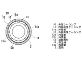
図1から図3に示すように、外側弁室ケーシング12は、内側弁室ケーシング11の外周面11aに沿って、内側弁室ケーシング11の半径方向外側を取り囲むようにして配置された板状の部材である。また、内側弁室ケーシング11の外周面11aと、外側弁室ケーシング12の内周面12aとの間には、弁室ケーシング10の軸方向(図1において上下方向)および周方向に沿って一定(例えば、10mm〜50mm)の隙間を有する空間Sが形成されている。
As shown in FIG. 1 to FIG. 3, the outer
図2および図3に示すように、内側弁室ケーシング11の外周面11aと、外側弁室ケーシング12の内周面12aとは、複数本(本実施形態では8本)の連結部材13を介して連結されている。連結部材13は、弁室ケーシング10の軸方向に沿って連続し、弁室ケーシング10の周方向に沿って間隔をあけて、内側弁室ケーシング11の外周面11aから半径方向外側に向かって放射状に延びる(突出する)板状の部材であり、本実施形態では、車室ケーシング3および内側弁室ケーシング11と同じ材料(例えば、2.25Cr鋳鋼)で、車室ケーシング3および内側弁室ケーシング11と一体的に鋳造されている。また、外側弁室ケーシング12の半径方向外側には、その内周面14a全体が外側弁室ケーシング12の外周面12b全体と接するとともに、外側弁室ケーシング12の外周面12b全体を覆い隠す保温材(または断熱材)14が設けられている。
As shown in FIGS. 2 and 3, the outer
本実施形態に係る弁室ケーシング10によれば、外側弁室ケーシング12の内周面12aと、内側弁室ケーシング11の外周面11aとにより形成された空間S内に存する空気は、内部に形成された流路を流れる蒸気により温められた(加熱された)内側弁室ケーシング11からの放熱により温められ(加熱され)、空間S内を上昇していくことになる。空間S内を上昇していった空気は、空間Sの上端に形成された出口から大気中に放出され、出口から大気中に放出された空気の量だけ、空間Sの下端に形成された入口から空間S内に、温度の低い新たな空気が流入して、内部に形成された流路を流れる蒸気により温められた(加熱された)内側弁室ケーシング11からの放熱により温められる(加熱される)ことになる。すなわち、空間S内に空気の上昇気流が発生し、内側弁室ケーシング11の熱が空間S内を上昇する空気に奪い去られて(吸熱されて)、内側弁室ケーシング11が冷却されることになる。
これにより、内部に形成された流路を通過する蒸気の温度を、例えば、約30℃上昇させたとしても、空間S内を自然に循環する空気の冷却効果により、内側弁室ケーシング11自体の温度上昇を低減させることができ、内側弁室ケーシング11を従来と同じ材料(例えば、2.25Cr鋳鋼)で製作することができ、製造コストの高騰を回避することができる。
According to the
Thereby, even if the temperature of the steam passing through the flow path formed inside is increased by, for example, about 30 ° C., the cooling effect of the air that naturally circulates in the space S allows the inner valve chamber casing 11 itself to The temperature rise can be reduced, and the inner valve chamber casing 11 can be made of the same material as the conventional one (for example, 2.25Cr cast steel), and an increase in manufacturing cost can be avoided.
また、本実施形態に係る弁室ケーシング10によれば、外側弁室ケーシング12の半径方向外側に、その内周面14a全体が外側弁室ケーシング12の外周面12b全体と接するとともに、外側弁室ケーシング12の外周面12b全体を覆い隠す保温材14が設けられている。
これにより、空間S内に存する空気が、内側弁室ケーシング11からの放熱により効率よく温められる(加熱される)ことになり、空間S内を上昇する空気の上昇速度を増加させることができ、空気による冷却効果をより高めるようにすることができる。
Moreover, according to the valve chamber casing 10 according to the present embodiment, the entire inner
Thereby, the air existing in the space S is efficiently heated (heated) by the heat radiation from the inner
〔第2実施形態〕
本発明の第2実施形態に係る弁室ケーシングについて、図4を参照しながら説明する。
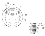
図4は本実施形態に係る弁室ケーシングの斜視図である。
[Second Embodiment]
A valve chamber casing according to a second embodiment of the present invention will be described with reference to FIG.
FIG. 4 is a perspective view of the valve chamber casing according to the present embodiment.
図4に示すように、本実施形態に係る弁室ケーシング10は、連結部材13の代わりに、連結部材23が設けられているという点で上述した第1実施形態のものと異なる。その他の構成要素については上述した第1実施形態のものと同じであるので、ここではそれら構成要素についての説明は省略する。
なお、上述した第1実施形態と同一の構成要素には、同一の符号を付してその説明を省略する。
As shown in FIG. 4, the valve chamber casing 10 according to this embodiment is different from that of the first embodiment described above in that a connecting
In addition, the same code | symbol is attached | subjected to the component same as 1st Embodiment mentioned above, and the description is abbreviate | omitted.
図4に示すように、内側弁室ケーシング11の外周面11aと、外側弁室ケーシング12の内周面12aとは、複数本(本実施形態では32本)の連結部材23を介して連結されている。連結部材23は、弁室ケーシング10の軸方向および周方向に沿って間隔をあけて、内側弁室ケーシング11の外周面11aから半径方向外側に向かって放射状に延びる(突出する)円柱状の部材であり、本実施形態では、車室ケーシング3および内側弁室ケーシング11と同じ材料(例えば、2.25Cr鋳鋼)で、車室ケーシング3および内側弁室ケーシング11と一体的に鋳造されている。
As shown in FIG. 4, the outer
本実施形態に係る弁室ケーシング10の作用効果は、上述した第1実施形態のものと同じであるので、ここではその説明を省略する。 Since the effect of the valve chamber casing 10 according to the present embodiment is the same as that of the first embodiment described above, the description thereof is omitted here.
〔第3実施形態〕
本発明の第3実施形態に係る弁室ケーシングについて、図5を参照しながら説明する。
図5は本実施形態に係る弁室ケーシングの斜視図である。
[Third Embodiment]
A valve chamber casing according to a third embodiment of the present invention will be described with reference to FIG.
FIG. 5 is a perspective view of the valve chamber casing according to the present embodiment.
図5に示すように、本実施形態に係る弁室ケーシング10は、連結部材13の代わりに、連結部材33が設けられているという点で上述した第1実施形態のものと異なる。その他の構成要素については上述した第1実施形態のものと同じであるので、ここではそれら構成要素についての説明は省略する。
なお、上述した第1実施形態と同一の構成要素には、同一の符号を付してその説明を省略する。
As shown in FIG. 5, the valve chamber casing 10 according to the present embodiment is different from that of the first embodiment described above in that a connecting
In addition, the same code | symbol is attached | subjected to the component same as 1st Embodiment mentioned above, and the description is abbreviate | omitted.
図5に示すように、内側弁室ケーシング11の外周面11aと、外側弁室ケーシング12の内周面12aとは、複数本(本実施形態では12本)の連結部材33を介して連結されている。連結部材33は、弁室ケーシング10の軸方向および周方向に沿って間隔をあけて、内側弁室ケーシング11の外周面11aから半径方向外側に向かって放射状に延びる(突出する)板状の部材であり、本実施形態では、車室ケーシング3および内側弁室ケーシング11と同じ材料(例えば、2.25Cr鋳鋼)で、車室ケーシング3および内側弁室ケーシング11と一体的に鋳造されている。
As shown in FIG. 5, the outer
本実施形態に係る弁室ケーシング10の作用効果は、上述した第1実施形態のものと同じであるので、ここではその説明を省略する。 Since the effect of the valve chamber casing 10 according to the present embodiment is the same as that of the first embodiment described above, the description thereof is omitted here.
〔第4実施形態〕
本発明の第4実施形態に係る弁室ケーシングについて、図6を参照しながら説明する。
図6は本実施形態に係る弁室ケーシングの斜視図である。
[Fourth Embodiment]
A valve chamber casing according to a fourth embodiment of the present invention will be described with reference to FIG.
FIG. 6 is a perspective view of the valve chamber casing according to the present embodiment.
図6に示すように、本実施形態に係る弁室ケーシング10は、連結部材13の代わりに、連結部材43が設けられているという点で上述した第1実施形態のものと異なる。その他の構成要素については上述した第1実施形態のものと同じであるので、ここではそれら構成要素についての説明は省略する。
なお、上述した第1実施形態と同一の構成要素には、同一の符号を付してその説明を省略する。
As shown in FIG. 6, the valve chamber casing 10 according to this embodiment is different from that of the first embodiment described above in that a connecting
In addition, the same code | symbol is attached | subjected to the component same as 1st Embodiment mentioned above, and the description is abbreviate | omitted.
図6に示すように、内側弁室ケーシング11の外周面11aと、外側弁室ケーシング12の内周面12aとは、複数本(本実施形態では8本)の連結部材43を介して連結されている。連結部材43は、弁室ケーシング10の軸方向に沿って連続し、弁室ケーシング10の周方向に沿って間隔をあけて、内側弁室ケーシング11の外周面11aから半径方向外側に向かって螺旋状に延びる(突出する)板状の部材であり、本実施形態では、車室ケーシング3および内側弁室ケーシング11と同じ材料(例えば、2.25Cr鋳鋼)で、車室ケーシング3および内側弁室ケーシング11と一体的に鋳造されている。
As shown in FIG. 6, the outer
本実施形態に係る弁室ケーシング10の作用効果は、上述した第1実施形態のものと同じであるので、ここではその説明を省略する。 Since the effect of the valve chamber casing 10 according to the present embodiment is the same as that of the first embodiment described above, the description thereof is omitted here.
本発明に係るタービン1は、内側弁室ケーシング11と車室ケーシング3とが、一体的に鋳造されている。
これにより、内側弁室ケーシング11と車室ケーシング3とを安価な材料(例えば、2.25Cr鋳鋼)で一体的に鋳造することができ、製造コストの高騰を回避することができる。
In the
Thereby, the inner
なお、本発明は上述した実施形態に限定されるものではなく、適宜必要に応じて変形・変更実施可能である。
例えば、上述した実施形態において、内側弁室ケーシング11の外周面11aに、図7に示すような断面視矩形状(または断面視半円形状)を呈する複数の突起(タービュレータまたはボルテックス・ジェネレータ)71を、弁室ケーシング10の軸方向および周方向に沿って間隔をあけて設けるとさらに好適である。
これにより、空間S内に存する空気が、内側弁室ケーシング11からの放熱によりさらに効率よく温められる(加熱される)ことになるので、空間S内を上昇する空気の上昇速度をさらに増加させることができ、空気による冷却効果をより一層高めるようにすることができる。
なお、図7は、突起71を第2実施形態に適用した場合を示している。
Note that the present invention is not limited to the above-described embodiment, and can be modified and changed as necessary.
For example, in the above-described embodiment, a plurality of protrusions (turbulators or vortex generators) 71 that have a rectangular shape (or semicircular shape in cross section) as shown in FIG. 7 on the outer
As a result, the air existing in the space S can be more efficiently warmed (heated) by the heat radiation from the inner
FIG. 7 shows a case where the
1 タービン
2 蒸気弁
3 車室ケーシング
4 弁体
5 弁座
6 弁棒
10 弁室ケーシング
11 内側弁室ケーシング
11a 外周面
12 外側弁室ケーシング
12a 内周面
12b 外周面
13 連結部材
14 保温材
14a 内周面
23 連結部材
33 連結部材
43 連結部材
71 突起
S 空間
DESCRIPTION OF
Claims (4)
内部に、弁体と、この弁体を弁座に対して進退させる弁棒とが収容された内側弁室ケーシングと、
その内周面と、前記内側弁室ケーシングの外周面との間に、隙間を有する空間が形成され、かつ、前記内側弁室ケーシングの半径方向外側を取り囲むようにして配置された外側弁室ケーシングと、
前記内側弁室ケーシングと前記外側弁室ケーシングとを連結する連結部材とを備えていることを特徴とする弁室ケーシング。 A valve chamber casing through which a high-temperature fluid flows through a flow path formed therein;
Inside, a valve body and an inner valve chamber casing in which a valve rod for moving the valve body forward and backward with respect to the valve seat is accommodated,
An outer valve chamber casing is formed so that a space having a gap is formed between the inner peripheral surface and the outer peripheral surface of the inner valve chamber casing, and is disposed so as to surround the radially outer side of the inner valve chamber casing. When,
A valve chamber casing comprising a connecting member for connecting the inner valve chamber casing and the outer valve chamber casing.
Priority Applications (1)
| Application Number | Priority Date | Filing Date | Title |
|---|---|---|---|
| JP2010294202A JP5766437B2 (en) | 2010-12-28 | 2010-12-28 | Valve chamber casing |
Applications Claiming Priority (1)
| Application Number | Priority Date | Filing Date | Title |
|---|---|---|---|
| JP2010294202A JP5766437B2 (en) | 2010-12-28 | 2010-12-28 | Valve chamber casing |
Publications (2)
| Publication Number | Publication Date |
|---|---|
| JP2012141013A true JP2012141013A (en) | 2012-07-26 |
| JP5766437B2 JP5766437B2 (en) | 2015-08-19 |
Family
ID=46677477
Family Applications (1)
| Application Number | Title | Priority Date | Filing Date |
|---|---|---|---|
| JP2010294202A Expired - Fee Related JP5766437B2 (en) | 2010-12-28 | 2010-12-28 | Valve chamber casing |
Country Status (1)
| Country | Link |
|---|---|
| JP (1) | JP5766437B2 (en) |
Cited By (1)
| Publication number | Priority date | Publication date | Assignee | Title |
|---|---|---|---|---|
| CN102829210A (en) * | 2012-08-22 | 2012-12-19 | 福建菲达阀门有限公司 | A high temperature unloading valve |
Citations (5)
| Publication number | Priority date | Publication date | Assignee | Title |
|---|---|---|---|---|
| JPS5672204A (en) * | 1979-11-14 | 1981-06-16 | Hitachi Ltd | Reducing device for thermal stress of main valve for steam turbine |
| JPS5881280A (en) * | 1981-11-09 | 1983-05-16 | Toshiba Corp | Main steam valve device |
| JPS58124009A (en) * | 1982-01-21 | 1983-07-23 | Toshiba Corp | Main steam valve device |
| JPH0491304A (en) * | 1990-08-02 | 1992-03-24 | Fuji Electric Co Ltd | Turbine casing |
| JP2009236039A (en) * | 2008-03-27 | 2009-10-15 | Toshiba Corp | Steam valve device and steam turbine plant equipped with the same |
-
2010
- 2010-12-28 JP JP2010294202A patent/JP5766437B2/en not_active Expired - Fee Related
Patent Citations (5)
| Publication number | Priority date | Publication date | Assignee | Title |
|---|---|---|---|---|
| JPS5672204A (en) * | 1979-11-14 | 1981-06-16 | Hitachi Ltd | Reducing device for thermal stress of main valve for steam turbine |
| JPS5881280A (en) * | 1981-11-09 | 1983-05-16 | Toshiba Corp | Main steam valve device |
| JPS58124009A (en) * | 1982-01-21 | 1983-07-23 | Toshiba Corp | Main steam valve device |
| JPH0491304A (en) * | 1990-08-02 | 1992-03-24 | Fuji Electric Co Ltd | Turbine casing |
| JP2009236039A (en) * | 2008-03-27 | 2009-10-15 | Toshiba Corp | Steam valve device and steam turbine plant equipped with the same |
Cited By (1)
| Publication number | Priority date | Publication date | Assignee | Title |
|---|---|---|---|---|
| CN102829210A (en) * | 2012-08-22 | 2012-12-19 | 福建菲达阀门有限公司 | A high temperature unloading valve |
Also Published As
| Publication number | Publication date |
|---|---|
| JP5766437B2 (en) | 2015-08-19 |
Similar Documents
| Publication | Publication Date | Title |
|---|---|---|
| JP5546876B2 (en) | Steam turbine | |
| JP5596042B2 (en) | Axially segmented guide vane mount for gas turbines | |
| CN102042043B (en) | For the vortex chamber of gap current control | |
| EP2067930A2 (en) | Seal structure for a steam turbine | |
| JP2015075118A (en) | Arrangement for cooling components in the hot gas passage of a gas turbine | |
| EP2295728A2 (en) | Steam turbine and cooling method of operating steam turbine | |
| JP2008240725A5 (en) | ||
| JP2015511678A (en) | Turbine blade | |
| JP2015078622A5 (en) | ||
| JP2012112379A (en) | Turbomachine nozzle segment having integrated diaphragm | |
| JP5955345B2 (en) | Fluid seal structure of heat engine including steam turbine | |
| JP5317814B2 (en) | Steam turbine | |
| JP5766437B2 (en) | Valve chamber casing | |
| JP6584687B2 (en) | Compressor bleed cooling system for a midframe torque disk downstream of a compressor assembly in a gas turbine engine | |
| JP5497055B2 (en) | Inner housing for turbomachinery | |
| JP6087803B2 (en) | Steam turbine | |
| JP4298166B2 (en) | Turbomachine with an inner housing and an outer housing | |
| CN102197195B (en) | Gas turbine having cooling insert | |
| JP2014148938A (en) | Film-cooled turbine blade for turbomachine | |
| JP6666280B2 (en) | On-off valve and steam turbine | |
| JP2014088817A (en) | Turbocharger | |
| JP6079669B2 (en) | Turbine housing | |
| JP5986952B2 (en) | Steam turbine self-adjusting seal | |
| JP5551268B2 (en) | Steam turbine with triple structure | |
| JP2014521870A (en) | Turbine system with push rod mechanism between two housings |
Legal Events
| Date | Code | Title | Description |
|---|---|---|---|
| A621 | Written request for application examination |
Free format text: JAPANESE INTERMEDIATE CODE: A621 Effective date: 20130920 |
|
| A977 | Report on retrieval |
Free format text: JAPANESE INTERMEDIATE CODE: A971007 Effective date: 20140828 |
|
| A131 | Notification of reasons for refusal |
Free format text: JAPANESE INTERMEDIATE CODE: A131 Effective date: 20140902 |
|
| A521 | Request for written amendment filed |
Free format text: JAPANESE INTERMEDIATE CODE: A523 Effective date: 20141104 |
|
| TRDD | Decision of grant or rejection written | ||
| A01 | Written decision to grant a patent or to grant a registration (utility model) |
Free format text: JAPANESE INTERMEDIATE CODE: A01 Effective date: 20150519 |
|
| A61 | First payment of annual fees (during grant procedure) |
Free format text: JAPANESE INTERMEDIATE CODE: A61 Effective date: 20150617 |
|
| R151 | Written notification of patent or utility model registration |
Ref document number: 5766437 Country of ref document: JP Free format text: JAPANESE INTERMEDIATE CODE: R151 |
|
| LAPS | Cancellation because of no payment of annual fees |