JP2012141012A - Drum brake - Google Patents

Drum brake Download PDF

Info

Publication number
JP2012141012A
JP2012141012A JP2010294148A JP2010294148A JP2012141012A JP 2012141012 A JP2012141012 A JP 2012141012A JP 2010294148 A JP2010294148 A JP 2010294148A JP 2010294148 A JP2010294148 A JP 2010294148A JP 2012141012 A JP2012141012 A JP 2012141012A
Authority
JP
Japan
Prior art keywords
brake
shoe
lever
adjustment
adjusting
Prior art date
Legal status (The legal status is an assumption and is not a legal conclusion. Google has not performed a legal analysis and makes no representation as to the accuracy of the status listed.)
Pending
Application number
JP2010294148A
Other languages
Japanese (ja)
Inventor
Masaki Horihara
昌樹 堀原
Current Assignee (The listed assignees may be inaccurate. Google has not performed a legal analysis and makes no representation or warranty as to the accuracy of the list.)
Hosei Brake Industry Co Ltd
Original Assignee
Hosei Brake Industry Co Ltd
Priority date (The priority date is an assumption and is not a legal conclusion. Google has not performed a legal analysis and makes no representation as to the accuracy of the date listed.)
Filing date
Publication date
Application filed by Hosei Brake Industry Co Ltd filed Critical Hosei Brake Industry Co Ltd
Priority to JP2010294148A priority Critical patent/JP2012141012A/en
Publication of JP2012141012A publication Critical patent/JP2012141012A/en
Pending legal-status Critical Current

Links

Images

Landscapes

  • Braking Arrangements (AREA)

Abstract

PROBLEM TO BE SOLVED: To provide a drum brake having an automatic shoe clearance adjusting mechanism capable of reducing the number of components in comparison with a conventional automatic shoe clearance adjusting mechanism.SOLUTION: In the drum brake, an adjustment lever 54 urges a first strut member 56 to the other brake shoe 18 side of a pair of brake shoes 18, 20 via a connection section 54e of the adjustment lever 54 by causing the tip of a spring section 54h integrally arranged on the adjustment lever 54 to come into press contact with an inner peripheral surface 38a of a shoe rim 38 of the brake shoe 20. Thus, functions of a spring prepared on the conventional automatic shoe clearance adjusting mechanism can be added to the adjustment lever 54, and the number of components used for the automatic shoe clearance adjusting mechanism 26 can be reduced in comparison with the conventional automatic shoe clearance adjusting mechanism.

Description

本発明は、ドラムブレーキに関し、特にそのドラムブレーキの非制動時における一対のブレーキシューと回転ドラムとの間のシュー間隙を自動的に調節するシュー間隙自動調節機構の部品点数を従来に比較して削減させる技術に関するものである。   The present invention relates to a drum brake, and in particular, compared with a conventional brake gap automatic adjustment mechanism that automatically adjusts a shoe gap between a pair of brake shoes and a rotating drum when the drum brake is not braked. It relates to technology to be reduced.

ドラムブレーキには、例えば特許文献1、2に示すように、(a) バッキングプレートに拡開可能に設けられた一対のブレーキシューの一方に係合する第1ストラット部材と、その一対のブレーキシューの他方に係合する第2ストラット部材と、アジャストホイールを備えてその第1ストラット部材と第2ストラット部材との間に配設されて少なくとも一方のストラット部材に螺合する調節軸とを有し、非制動時におけるその一対のブレーキシューの待機位置を規定するストラットと、(b) 制動時における前記一対のブレーキシューの拡開量に応じて回動させられて前記アジャストホイールを一方向に回動させるアジャストレバーとを有し、(c) 前記アジャストレバーによって前記アジャストホイールが回動させられることにより前記ストラットが伸長し、非制動時における前記一対のブレーキシューと回転ドラムとの間のシュー間隙を自動的に調節する車両用ドラムブレーキのシュー間隙自動調節機構を備えるものがある。   For example, as shown in Patent Documents 1 and 2, the drum brake includes (a) a first strut member that engages with one of a pair of brake shoes provided on the backing plate so as to be expandable, and the pair of brake shoes. A second strut member that engages the other of the first strut member, and an adjustment shaft that is provided between the first strut member and the second strut member and includes an adjustment wheel that is screwed into at least one strut member. A strut that defines the standby position of the pair of brake shoes during non-braking, and (b) is rotated according to the amount of expansion of the pair of brake shoes during braking to rotate the adjustment wheel in one direction. And (c) the strut is moved by rotating the adjustment wheel by the adjustment lever. It poured, there is provided an automatic adjusting to the automatic shoe clearance adjustment mechanism of a vehicle drum brake shoe gap between the pair of brake shoes and the rotary drum at the time of non-braking.

上記のようなシュー間隙自動調節機構を備えるドラムブレーキにおいて、例えば特許文献1のドラムブレーキ10に示すように、シュー間隙自動調節機構26に備えられたアジャストレバー54は、第1ストラット部材56と当接する当接部54dと、その当接部54dを介して第1ストラット部材56すなわちストラットを一対のブレーキシュー18,20の他方のブレーキシュー18側に付勢させるスプリング62の一端部を掛け止める掛止部とを備えており、その掛止部と一対のブレーキシュー18,20の一方のブレーキシュー20との間で張設されたスプリング62の弾性復帰力によってそのアジャストレバー54の当接部54dが一対のブレーキシュー18,20の他方のブレーキシュー18側に回動するように付勢される。そのため、ホイールシリンダ22によって一対のブレーキシュー18,20が拡開するとその拡開量に応じてアジャストレバー54の当接部54dが第1ストラット部材56と当接するまで一対のブレーキシュー18,20の他方のブレーキシュー18側に回動させられ、その回動量に応じてアジャストレバー54によってアジャストホイール44が回動させられて、シュー間隙が調節される。   In the drum brake having the shoe gap automatic adjusting mechanism as described above, for example, as shown in the drum brake 10 of Patent Document 1, the adjustment lever 54 provided in the shoe gap automatic adjusting mechanism 26 is in contact with the first strut member 56. A contact portion 54d that comes into contact with the first strut member 56, that is, one end portion of the spring 62 that urges the strut to the other brake shoe 18 side of the pair of brake shoes 18 and 20 via the contact portion 54d. And a contact portion 54d of the adjusting lever 54 by an elastic return force of a spring 62 stretched between the hook portion and one brake shoe 20 of the pair of brake shoes 18, 20. Is biased so as to rotate toward the other brake shoe 18 side of the pair of brake shoes 18 and 20. Therefore, when the pair of brake shoes 18, 20 are expanded by the wheel cylinder 22, the pair of brake shoes 18, 20 are moved until the contact portion 54 d of the adjustment lever 54 contacts the first strut member 56 according to the expansion amount. The other side of the brake shoe 18 is rotated, and the adjusting wheel 44 is rotated by the adjusting lever 54 in accordance with the amount of rotation, thereby adjusting the shoe gap.

特開2010−133456号公報JP 2010-133456 A 特開2002−147506号公報JP 2002-147506 A

しかしながら、上記のようなシュー間隙自動調節機構26を備えるドラムブレーキ10において、第1ストラット部材56すなわちストラットを一対のブレーキシュー18,20の他方のブレーキシュー18側に付勢させるためにスプリング62が設けられるので、その分シュー間隙自動調節機構26の部品点数が増加してしまうという問題があった。   However, in the drum brake 10 including the shoe gap automatic adjusting mechanism 26 as described above, the spring 62 is used to bias the first strut member 56, that is, the strut toward the other brake shoe 18 side of the pair of brake shoes 18 and 20. Therefore, there is a problem that the number of parts of the shoe gap automatic adjusting mechanism 26 increases accordingly.

本発明は、以上の事情を背景として為されたものであって、その目的とするところは、従来のシュー間隙自動調節機構に比べ部品点数が削減させられるシュー間隙自動調節機構を備えたドラムブレーキを提供することにある。   The present invention has been made against the background of the above circumstances, and the object of the present invention is to provide a drum brake equipped with an automatic shoe clearance adjustment mechanism that can reduce the number of parts compared to a conventional shoe clearance automatic adjustment mechanism. Is to provide.

かかる目的を達成するための請求項1に係る発明の要旨とするところは、(a) バッキングプレートに拡開可能に設けられた一対のブレーキシューの一方に係合する第1ストラット部材と、その一対のブレーキシューの他方に係合する第2ストラット部材と、アジャストホイールを備えてその第1ストラット部材と第2ストラット部材との間に配設されて少なくとも一方のストラット部材に螺合する調節軸とを有し、非制動時におけるその一対のブレーキシューの待機位置を規定するストラットと、(b) 制動時における前記一対のブレーキシューの拡開量に応じて回動させられて前記アジャストホイールを一方向に回動させるアジャストレバーとを有し、(c) 前記アジャストレバーによって前記アジャストホイールが回動させられることにより前記ストラットが伸長し、非制動時における前記一対のブレーキシューと回転ドラムとの間のシュー間隙を自動的に調節する車両用ドラムブレーキのシュー間隙自動調節機構を備えたドラムブレーキにおいて、(d) 前記アジャストレバーは、一枚の板材からプレス加工されることによって、前記第1ストラット部材と係合する係合部と、その係合部を介して前記第1ストラット部材を前記一対のブレーキシューの他方側に付勢するばね部とを一体に備えており、(e) 前記アジャストレバーのばね部は、先端部が前記ブレーキシューのシューリムの内周面と圧接させられることによって、前記アジャストレバーを前記一方向或いは前記一方向の反対方向に回動するように付勢するものである。   To achieve this object, the gist of the invention according to claim 1 is that: (a) a first strut member that engages with one of a pair of brake shoes provided on the backing plate so as to be expandable; A second strut member that engages the other of the pair of brake shoes, and an adjustment shaft that is provided between the first strut member and the second strut member and includes an adjustment wheel and is screwed into at least one strut member. A strut that defines the standby position of the pair of brake shoes during non-braking, and (b) is rotated according to the amount of expansion of the pair of brake shoes during braking. An adjustment lever that rotates in one direction, and (c) the adjustment wheel is rotated by the adjustment lever, thereby In a drum brake provided with a shoe gap automatic adjustment mechanism of a vehicle drum brake that automatically adjusts a shoe gap between the pair of brake shoes and the rotating drum when the trat extends and is not braked, (d) The adjustment lever is pressed from a single plate member, thereby engaging the first strut member with the first strut member via the engagement portion and the other of the pair of brake shoes. And (e) the spring portion of the adjustment lever is configured such that the tip of the spring portion of the adjustment lever is brought into pressure contact with the inner peripheral surface of the shoe rim of the brake shoe. It is urged to rotate in one direction or in the opposite direction to the one direction.

また、請求項2に係る発明の要旨とするところは、請求項1に係る発明において、(a) 前記アジャストレバーの回動中心部には、前記一対のブレーキシューの一方のシューウェブに突設された軸部材を相対回転可能に嵌め入れる嵌合穴が穿設されており、(b) 前記アジャストレバーは、その嵌合穴に前記軸部材が嵌め入れられることにより前記ブレーキシューに相対回転可能に配設され、(c) 前記アジャストレバーのばね部は、そのアジャストレバーの係合部から一体に延長されるものである。   The gist of the invention according to claim 2 is that, in the invention according to claim 1, (a) the adjustment lever is provided at one pivot web of the pair of brake shoes at the center of rotation. (B) The adjustment lever is rotatable relative to the brake shoe by fitting the shaft member into the fitting hole. (C) The spring portion of the adjusting lever is integrally extended from the engaging portion of the adjusting lever.

請求項1に係る発明のドラムブレーキによれば、前記アジャストレバーは、一枚の板材からプレス加工されることによって、前記第1ストラット部材と係合する係合部と、その係合部を介して前記第1ストラット部材を前記一対のブレーキシューの他方側に付勢するばね部とを一体に備えており、前記アジャストレバーのばね部は、先端部が前記ブレーキシューのシューリムの内周面と圧接させられることによって、前記アジャストレバーを前記一方向或いは前記一方向の反対方向に回動するように付勢するものである。このため、前記アジャストレバーは、そのアジャストレバーに一体に備えられたばね部の先端部が前記ブレーキシューのシューリムの内周面と圧接させられることによって、そのアジャストレバーの係合部を介して第1ストラット部材を前記一対のブレーキシューの他方側に付勢するので、従来のシュー間隙自動調節機構に備えられたスプリングの機能を前記アジャストレバーに追加することができ従来のシュー間隙自動調節機構に比べ部品点数を削減させることができる。   According to the drum brake of the first aspect of the present invention, the adjustment lever is pressed from a single plate material, thereby engaging the first strut member with the engagement portion interposed therebetween. And a spring portion that biases the first strut member toward the other side of the pair of brake shoes, and the spring portion of the adjust lever has a tip portion that is connected to an inner peripheral surface of the shoe rim of the brake shoe. By being brought into pressure contact, the adjusting lever is urged to rotate in one direction or in the opposite direction of the one direction. For this reason, the adjustment lever is configured such that the distal end portion of the spring portion provided integrally with the adjustment lever is brought into pressure contact with the inner peripheral surface of the shoe rim of the brake shoe, so that the first adjustment lever is engaged via the engagement portion of the adjustment lever. Since the strut member is urged to the other side of the pair of brake shoes, the spring function provided in the conventional shoe gap automatic adjustment mechanism can be added to the adjustment lever, compared with the conventional shoe gap automatic adjustment mechanism. The number of parts can be reduced.

請求項2に係る発明のドラムブレーキによれば、前記アジャストレバーの回動中心部には、前記一対のブレーキシューの一方のシューウェブに突設された軸部材を相対回転可能に嵌め入れる嵌合穴が穿設されており、前記アジャストレバーは、その嵌合穴に前記軸部材が嵌め入れられることにより前記ブレーキシューに相対回転可能に配設され、前記アジャストレバーのばね部は、そのアジャストレバーの係合部から一体に延長されるものである。このため、前記ばね部の先端部が前記ブレーキシューのシューリムの内周面と圧接させられた力が直接前記アジャストレバーの係合部に伝達されその力による前記アジャストレバーの前記軸部材まわりの力のモーメントが好適に大きくされるので、前記アジャストレバーの係合部を介して前記第1ストラット部材を前記一対のブレーキシューの他方側に付勢させる付勢力が好適に向上する。   According to the drum brake of the invention according to claim 2, the shaft member protruding from one shoe web of the pair of brake shoes is fitted into the pivot center portion of the adjustment lever so as to be relatively rotatable. A hole is formed, and the adjustment lever is disposed so as to be rotatable relative to the brake shoe by fitting the shaft member into the fitting hole, and the spring portion of the adjustment lever includes the adjustment lever. It extends integrally from the engaging part. For this reason, the force that the tip of the spring portion is brought into pressure contact with the inner peripheral surface of the shoe rim of the brake shoe is directly transmitted to the engaging portion of the adjusting lever, and the force around the shaft member of the adjusting lever by the force is transmitted. Therefore, the urging force for urging the first strut member to the other side of the pair of brake shoes via the engaging portion of the adjustment lever is preferably improved.

本発明が適用された一実施例のシュー間隙自動調節機構付のリーディング・トレーリング型ドラムブレーキを示す正面図である。1 is a front view showing a leading / trailing drum brake with an automatic shoe clearance adjusting mechanism according to an embodiment to which the present invention is applied. FIG. 図1のII-II視断面図である。It is the II-II sectional view taken on the line of FIG. アジャストレバーを説明するための図2のIII-III視断面図である。FIG. 3 is a cross-sectional view taken along the line III-III in FIG. 図2のIV-IV視断面図であり、一対のブレーキシューが拡開することにより、アジャストレバーの係合板が回動して、噛み合っているアジャストホイールの係合歯を矢印B方向に回す状態を示す図である。FIG. 4 is a cross-sectional view taken along the line IV-IV in FIG. 2, in which a pair of brake shoes expands to rotate the adjusting lever engaging plate and rotate the engaging teeth of the adjusting wheel engaged in the direction of arrow B FIG. 他の実施例のアジャストレバーを示す図であり、前述の実施例1の図3に対応する図である。It is a figure which shows the adjustment lever of another Example, and is a figure corresponding to FIG. 3 of above-mentioned Example 1. FIG. 他の実施例のアジャストレバーを示す図であり、前述の実施例1の図3に対応する図である。It is a figure which shows the adjustment lever of another Example, and is a figure corresponding to FIG. 3 of above-mentioned Example 1. FIG. 他の実施例のアジャストレバーを示す図であり、前述の実施例1の図3に対応する図である。It is a figure which shows the adjustment lever of another Example, and is a figure corresponding to FIG. 3 of above-mentioned Example 1. FIG.

以下、本発明の一実施例を図面を参照して詳細に説明する。なお、以下の実施例において図は適宜簡略化或いは変形されており、各部の寸法比および形状等は必ずしも正確に描かれていない。   Hereinafter, an embodiment of the present invention will be described in detail with reference to the drawings. In the following embodiments, the drawings are appropriately simplified or modified, and the dimensional ratios, shapes, and the like of the respective parts are not necessarily drawn accurately.

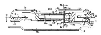
図1は、本発明の一実施例のパーキングロック機能を備えたシュー間隙自動調節機構付ドラムブレーキであるリーディング・トレーリング型の車両用ドラムブレーキ(以下、ドラムブレーキという)10であって、有底円筒状のブレーキドラム(回転ドラム)12を取り外して示す正面図である。また、ブレーキドラム12は、図1の1点鎖線で示す2つの同心円で表されており、その2つの円のうちの中心側の円はブレーキドラム12の内周面14を示している。   FIG. 1 shows a leading / trailing type vehicle drum brake (hereinafter referred to as a drum brake) 10 which is a drum brake with a shoe clearance automatic adjustment mechanism having a parking lock function according to an embodiment of the present invention. FIG. 3 is a front view showing a bottom cylindrical brake drum (rotary drum) 12 removed. Further, the brake drum 12 is represented by two concentric circles indicated by a one-dot chain line in FIG. 1, and the circle on the center side of the two circles indicates the inner peripheral surface 14 of the brake drum 12.

ドラムブレーキ10には、略円板形状を成し、たとえば図示しない車軸管、アクスルハウジング、サスペンション装置などの車体側部材すなわち非回転部材に一体的に固設されたバッキングプレート16が備えられている。   The drum brake 10 has a substantially disc shape, and includes a backing plate 16 that is integrally fixed to a vehicle body side member such as an axle tube, an axle housing, and a suspension device (not shown), that is, a non-rotating member. .

また、ドラムブレーキ10には、バッキングプレート16の外周部に凸側が外側になる姿勢で互いに接近離間可能に略対称的に配設された円弧形状の一対のブレーキシュー18,20と、その一対のブレーキシュー18,20の一端部すなわち図1の上端部の間においてバッキングプレート16に位置固定に設けられたホイールシリンダ22と、一対のブレーキシュー18,20の一端部を互いに接近する方向に常時付勢してホイールシリンダ22に当接させるために、その一端部間に張設されたコイル状のリターンスプリング24と、そのコイル状のリターンスプリング24の内部を挿通するように一対のブレーキシュー18,20の一端部間に架け渡された非制動時における一対のブレーキシュー18,20とブレーキドラム12との間すなわちシュー間隙を自動的に調節するシュー間隙自動調節機構26と、一対のブレーキシュー18,20の他端部すなわち図1の下端部の間に位置固定に設けられたアンカー28と、一対のブレーキシュー18,20の他端部間に張設されてそれら他端部をアンカー28に常時当接させるスプリング30とが備えられている。   The drum brake 10 includes a pair of arc-shaped brake shoes 18 and 20 disposed substantially symmetrically so as to be able to approach and separate from each other in a posture in which the convex side is on the outer side of the backing plate 16, and the pair of brake shoes 18 and 20. A wheel cylinder 22 provided in a fixed position on the backing plate 16 between one end of the brake shoes 18 and 20, that is, the upper end of FIG. 1, and one end of the pair of brake shoes 18 and 20 are always attached in a direction approaching each other. In order to urge the wheel cylinder 22 into contact with the wheel cylinder 22, a coiled return spring 24 stretched between one end portions thereof and a pair of brake shoes 18 so as to be inserted through the inside of the coiled return spring 24, 20 between the pair of brake shoes 18 and 20 and the brake drum 12 when not braked. That is, a shoe gap automatic adjusting mechanism 26 that automatically adjusts the shoe gap, an anchor 28 provided in a fixed position between the other ends of the pair of brake shoes 18 and 20, that is, the lower ends of FIG. A spring 30 is provided which is stretched between the other end portions of the brake shoes 18 and 20 so as to always contact the other end portion with the anchor 28.

一対のブレーキシュー18,20は、何れも、バッキングプレート16の内周部に位置する平坦な平板部16aと略平行な平板状を成し且つ図1に示す正面図において全体が円弧形状に湾曲したシューウェブ32,34と、それらの円弧形状を成すシューウェブ32,34の外周側端縁に沿って断面が略T字状を成すようにそのシューウェブ32,34に一体的に固設された帯板状のシューリム36,38と、それらシューリム36,38の外周面に接着剤などで一体的に固着された摩擦材から成るライニング40,42とを備えてそれぞれ構成されている。また、一対のブレーキシュー18,20は、シューウェブ32およびシューウェブ34にそれぞれ配設されたシューホールドダウン装置44,46によってバッキングプレート16側へ押圧されることによりそのバッキングプレート16に対して面方向の相対移動可能に保持されている。また、ブレーキシュー18の一端部には、平板状のパーキングブレーキレバー48の基端部48aがピン50により相対回動可能に連結されている。バッキングプレート16、シューウェブ32,34、シューリム36,38は、いずれも鋼板から打ち抜かれ且つ所定の曲げ成形が施されたプレス部品である。   Each of the pair of brake shoes 18 and 20 has a flat plate shape substantially parallel to the flat flat plate portion 16a located on the inner peripheral portion of the backing plate 16, and is entirely curved in an arc shape in the front view shown in FIG. The shoe webs 32 and 34 are integrally fixed to the shoe webs 32 and 34 so that the cross-sections are substantially T-shaped along the outer peripheral side edges of the shoe webs 32 and 34 forming the arc shape thereof. The belt-like shoe rims 36 and 38 and the linings 40 and 42 made of a friction material integrally fixed to the outer peripheral surfaces of the shoe rims 36 and 38 with an adhesive or the like are provided. The pair of brake shoes 18 and 20 are pressed against the backing plate 16 by being pressed toward the backing plate 16 by shoe hold-down devices 44 and 46 respectively disposed on the shoe web 32 and the shoe web 34. It is held so that it can move in the relative direction. A base end 48 a of a flat parking brake lever 48 is connected to one end of the brake shoe 18 by a pin 50 so as to be relatively rotatable. The backing plate 16, the shoe webs 32 and 34, and the shoe rims 36 and 38 are all pressed parts that are punched from a steel plate and subjected to predetermined bending.

シュー間隙自動調節機構26は、図1に示すように、一対のブレーキシュー18,20の一端部間に架け渡された非制動時における一対のブレーキシュー18,20の待機位置を規定するストラット52と、そのストラット52の一部に係合するアジャストレバー54とによって構成されている。   As shown in FIG. 1, the shoe gap automatic adjusting mechanism 26 is struts 52 that define a standby position of the pair of brake shoes 18, 20 that is spanned between one end portions of the pair of brake shoes 18, 20 during non-braking. And an adjustment lever 54 that engages with a part of the strut 52.

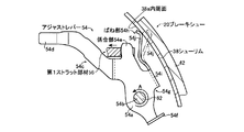
図2に示すように、ストラット52は、一方のブレーキシュー20のシューウェブ34に係合する第1係合凹部56aを有する第1ストラット部材56と、他方のブレーキシュー18のシューウェブ32およびパーキングブレーキレバー48の基端部48aに係合する第2係合凹部58aを有する第2ストラット部材58と、略円板形状のアジャストホイール60aを備えて第1ストラット部材56と第2ストラット部材58との間に配設され第2ストラット部材58と螺合する調節軸60とによって構成されている。   As shown in FIG. 2, the strut 52 includes a first strut member 56 having a first engagement recess 56 a that engages with the shoe web 34 of one brake shoe 20, the shoe web 32 and parking of the other brake shoe 18. A second strut member 58 having a second engagement recess 58a that engages with a base end portion 48a of the brake lever 48, a substantially disc-shaped adjustment wheel 60a, and a first strut member 56 and a second strut member 58, And an adjusting shaft 60 that is screwed with the second strut member 58.

また、図2に示すように、調節軸60は、略円板形状のアジャストホイール60aの中心部から第1ストラット部材56側に略円柱形状に突き出す嵌合軸部60bと、略円板形状のアジャストホイール60aの中心部からその嵌合軸部60bとは反対方向すなわち第2ストラット部材58側に略円柱形状に突設すると共にその外周面が螺刻された雄ねじ部60cを有するねじ軸部60dとから構成されている。また、調節軸60において、ねじ軸部60dは第2ストラット部材58に略円柱形状に穿設されその内周面が螺刻された雌ねじ穴58bと螺合し、嵌合軸部60bは第1ストラット部材56に穿設された略円柱形状の嵌合穴56bに相対回転可能に嵌め入れられている。   In addition, as shown in FIG. 2, the adjustment shaft 60 includes a fitting shaft portion 60b that protrudes in a substantially cylindrical shape from the center portion of the substantially disc-shaped adjustment wheel 60a toward the first strut member 56 side, and a substantially disc-shaped adjustment wheel 60a. A screw shaft portion 60d having a male screw portion 60c projecting in a substantially cylindrical shape from the center portion of the adjustment wheel 60a in a direction opposite to the fitting shaft portion 60b, that is, on the second strut member 58 side, and having an outer peripheral surface threaded. It consists of and. Further, in the adjustment shaft 60, the screw shaft portion 60d is screwed into a female screw hole 58b that is formed in the second strut member 58 in a substantially cylindrical shape and the inner peripheral surface of which is threaded, and the fitting shaft portion 60b is the first shaft portion 60b. The strut member 56 is fitted into a substantially columnar fitting hole 56b that is relatively rotatable.

そのため、アジャストレバー54によってアジャストホイール60aが所定方向に回動させられると、調節軸60のねじ軸部60dと第2ストラット部材58の雌ねじ穴58bとのねじの作用によって第2ストラット部材58がブレーキシュー18側に移動させられてストラット52が伸長する。また、ブレーキシュー18および20には、図1に示すように第1ストラット部材56および第2ストラット部材58すなわちストラット52を支持するために相手に向かって突出した支持突起18aおよび20aがそれぞれ形成されている。   Therefore, when the adjustment wheel 60a is rotated in a predetermined direction by the adjustment lever 54, the second strut member 58 is braked by the action of the screw shaft portion 60d of the adjustment shaft 60 and the female screw hole 58b of the second strut member 58. The strut 52 is extended by being moved to the shoe 18 side. Further, as shown in FIG. 1, the brake shoes 18 and 20 are respectively formed with support protrusions 18a and 20a that protrude toward the other side in order to support the first strut member 56 and the second strut member 58, that is, the strut 52. ing.

アジャストレバー54は、一枚の金属板材例えば綱板からプレス加工されることによって図1乃至図3に示すように成形されており、そのアジャストレバー54の回動中心部54aに貫通された嵌合穴54bにシューウェブ34に突設された略円柱形状の軸部材62が相対回転可能に嵌め入れられることによって、アジャストレバー54はその軸部材62回りに相対回動可能にブレーキシュー20のシューウェブ34に配設されている。   The adjustment lever 54 is formed as shown in FIGS. 1 to 3 by being pressed from a single metal plate, for example, a steel plate, and is fitted into the rotation center portion 54a of the adjustment lever 54. By fitting a substantially cylindrical shaft member 62 projecting from the shoe web 34 into the hole 54b so as to be relatively rotatable, the adjust lever 54 can be relatively rotated around the shaft member 62. 34.

また、アジャストレバー54は、図1乃至図3に示すように、その回動中心部54aからアジャストホイール60a側に長手状に延長された延長部54cと、その延長部54cの先端部から略円板形状のアジャストホイール60aの外周面に備えられた複数の係合歯60eの一つに伸長し図示されていないブレーキペダル操作によるブレーキ制動時にその係合歯60eと係合する平板状の係合板54dと、延長部54cの中間部から第1ストラット部材56側に伸長しその第1ストラット部材56の第1係合凹部56aに係合する係合部54eと、回動中心部54aからブレーキシュー20のシューウェブ34の所定位置に貫通された貫通穴34aを通り先端部をその貫通穴34aの周辺部に掛止する抜止め突部54fと、アジャストレバー54のシューリム38側の端縁における軸部材62に対して係合部54e側の一部の端縁部54gから先端部がブレーキシュー20のシューリム38側に延長されるばね部54hとを一体的に備えている。   Further, as shown in FIGS. 1 to 3, the adjustment lever 54 has an extension portion 54c extending in a longitudinal direction from the rotation center portion 54a toward the adjustment wheel 60a, and a substantially circular shape from the distal end portion of the extension portion 54c. A flat engaging plate that extends to one of a plurality of engaging teeth 60e provided on the outer peripheral surface of the plate-shaped adjusting wheel 60a and engages with the engaging teeth 60e during brake braking by a brake pedal operation (not shown). 54d, an engagement portion 54e extending from the intermediate portion of the extension portion 54c toward the first strut member 56 and engaging with the first engagement recess 56a of the first strut member 56, and a brake shoe from the rotation center portion 54a. A retaining projection 54f that passes through a through hole 34a penetrated to a predetermined position of the 20 shoe webs 34 and hooks the tip portion to the peripheral portion of the through hole 34a; and an adjustment lever 4 is integrally formed with a spring portion 54h whose tip is extended from the end edge portion 54g on the engagement portion 54e side to the shoe rim 38 side of the brake shoe 20 with respect to the shaft member 62 at the end edge on the shoe rim 38 side. In preparation.

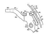
図3に示すように、アジャストレバー54のばね部54hは、そのアジャストレバー54の端縁部54gからバッキングプレート16側に曲げられる曲げ部54iと、その曲げ部54iの係合部54e側の側面から先端部がシューリム38の内周面38aと圧接するように延長される板ばね部54jとを一体に備えている。また、アジャストレバー54の曲げ部54iは、図2に示すように、板ばね部54jがリターンスプリング24の一端部と接触しないようにその曲げ部54iがバッキングプレート16側に曲げ延ばされている。   As shown in FIG. 3, the spring portion 54h of the adjustment lever 54 includes a bent portion 54i bent toward the backing plate 16 from the end edge portion 54g of the adjust lever 54, and a side surface on the engaging portion 54e side of the bent portion 54i. And a leaf spring portion 54j that is extended so that the tip portion is in pressure contact with the inner peripheral surface 38a of the shoe rim 38. Further, as shown in FIG. 2, the bent portion 54 i of the adjusting lever 54 is bent and extended toward the backing plate 16 so that the leaf spring portion 54 j does not come into contact with one end portion of the return spring 24. .

図3の一点鎖線で示す板ばね部54jは、アジャストレバー54がシュー間隙自動調節機構26に組み付けられる前すなわちアジャストレバー54の板ばね部54jに外力が加えられていない状態を示すものである。この図3の一点鎖線の板ばね部54jが示すように、アジャストレバー54がシュー間隙自動調節機構26に組み付けられると板ばね部54jの先端部がブレーキシュー20のシューリム38の内周面38aによって係合部54eに接近する方向にその板ばね部54jが弾性変形させられる。そのため、アジャストレバー54の板ばね部54jは、その板ばね部54jの弾性復帰力によってアジャストレバー54の係合部54eをブレーキシュー18側に軸部材62回りに回動するようにすなわち矢印A方向に回動するように付勢し、第1ストラット部材56すなわちストラット52をアジャストレバー54の係合部54eを介してブレーキシュー18側に付勢する。   A leaf spring portion 54j indicated by a one-dot chain line in FIG. 3 indicates a state in which an external force is not applied to the leaf spring portion 54j of the adjustment lever 54 before the adjustment lever 54 is assembled to the shoe gap automatic adjustment mechanism 26. As indicated by the one-dot chain line leaf spring portion 54j in FIG. 3, when the adjusting lever 54 is assembled to the shoe gap automatic adjusting mechanism 26, the tip end portion of the leaf spring portion 54j is supported by the inner peripheral surface 38a of the shoe rim 38 of the brake shoe 20. The leaf spring portion 54j is elastically deformed in a direction approaching the engaging portion 54e. For this reason, the leaf spring portion 54j of the adjustment lever 54 rotates the engagement portion 54e of the adjustment lever 54 around the shaft member 62 toward the brake shoe 18 by the elastic restoring force of the leaf spring portion 54j, that is, in the direction of arrow A. The first strut member 56, that is, the strut 52 is urged toward the brake shoe 18 via the engaging portion 54 e of the adjustment lever 54.

以上のように構成されたドラムブレーキ10は、ブレーキペダルが操作されないブレーキ非制動時において、アジャストレバー54がその板ばね部54jの付勢力によって矢印A方向に回動しようとするがその係合部54eが第1ストラット部材56の第1係合凹部56aに受け止められているのでその回動が抑止される。また、リターンスプリング24の付勢力は、アジャストレバー54の板ばね部54jの付勢力より大きいため、その板ばね部54jの付勢力によってアジャストレバー54の係合部54eが第1ストラット部材56すなわちストラット52をブレーキシュー18側へ移動するように付勢しても一対のブレーキシュー18,20は拡開しない。   In the drum brake 10 configured as described above, the adjusting lever 54 tries to rotate in the direction of arrow A by the urging force of the leaf spring portion 54j when the brake is not braked when the brake pedal is not operated. Since 54e is received by the 1st engagement recessed part 56a of the 1st strut member 56, the rotation is suppressed. Further, since the urging force of the return spring 24 is larger than the urging force of the leaf spring portion 54j of the adjusting lever 54, the engaging portion 54e of the adjusting lever 54 is moved by the urging force of the leaf spring portion 54j to the first strut member 56, that is, the strut. The pair of brake shoes 18 and 20 does not expand even if the force is applied to move the brake 52 toward the brake shoe 18 side.

また、ブレーキペダルが操作されるブレーキ制動時において、ホイールシリンダ22によって一対のブレーキシュー18,20が拡開すると、アジャストレバー54の係合部54eはその板ばね部54jの付勢力によって第2ストラット部材58がパーキングブレーキレバー48と当接するようにストラット52をブレーキシュー18側に移動させる。すなわち、ブレーキペダルが操作されるブレーキ制動時において、一対のブレーキシュー18,20の拡開量と第1ストラット部材56とブレーキシュー20との隙間とは略同じであり、一対のブレーキシュー18,20の拡開量に応じてアジャストレバー54はその係合部54eが第1ストラット部材56と当接して止められるまで矢印A方向に回動する。   Further, when the pair of brake shoes 18 and 20 are expanded by the wheel cylinder 22 during brake braking in which the brake pedal is operated, the engaging portion 54e of the adjusting lever 54 is moved to the second strut by the urging force of the leaf spring portion 54j. The strut 52 is moved toward the brake shoe 18 so that the member 58 contacts the parking brake lever 48. That is, at the time of brake braking in which the brake pedal is operated, the spread amount of the pair of brake shoes 18 and 20 and the gap between the first strut member 56 and the brake shoe 20 are substantially the same. The adjustment lever 54 rotates in the direction of the arrow A until the engaging portion 54e comes into contact with the first strut member 56 and is stopped according to the amount of expansion of 20.

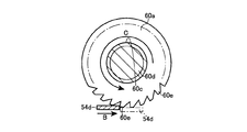
図4は、ブレーキペダルが操作されるブレーキ制動時において、一対のブレーキシュー18,20が拡開することにより、アジャストレバー54の係合板54dが回動して、噛み合っているアジャストホイール60aの係合歯60eを矢印B方向に回す状態を示す図である。この図4によれば、ブレーキペダル操作によって一対のブレーキシュー18,20が拡開してアジャストレバー54の板ばね部54jの付勢力によりアジャストレバー54が矢印A方向に回動すると、アジャストレバー54の係合板54dはそのアジャストレバー54の回動に連動して矢印B方向に移動する。アジャストレバー54の係合板54dが矢印B方向に移動することによって、そのアジャストレバー54の係合板54dがアジャストホイール60aの係合歯60eと係合して噛み合い、さらにアジャストレバー54の係合板54dが矢印B方向に移動するとその係合板54dがアジャストホイール60aの外周側に弾性変形されながらアジャストホイール60aが矢印C方向に回動させられ、ストラット52が伸長して一対のブレーキシュー18,20とブレーキドラム12の内周面14とのシュー間隙が自動的に調節される。また、図4の一点鎖線は、アジャストレバー54の係合板54dが一対のブレーキシュー18,20の拡開によって矢印B方向に移動した状態を示すものである。   FIG. 4 shows a relationship between the engaging wheel 60a engaged with the engaging plate 54d of the adjusting lever 54 rotated by the expansion of the pair of brake shoes 18 and 20 during the braking operation when the brake pedal is operated. It is a figure which shows the state which rotates the artificial tooth 60e to the arrow B direction. According to FIG. 4, when the pair of brake shoes 18, 20 are expanded by operating the brake pedal and the adjusting lever 54 is rotated in the direction of arrow A by the urging force of the leaf spring portion 54 j of the adjusting lever 54, the adjusting lever 54 The engaging plate 54d moves in the direction of arrow B in conjunction with the rotation of the adjusting lever 54. When the engaging plate 54d of the adjusting lever 54 moves in the direction of arrow B, the engaging plate 54d of the adjusting lever 54 engages and engages with the engaging teeth 60e of the adjusting wheel 60a, and the engaging plate 54d of the adjusting lever 54 further engages. When moved in the direction of arrow B, the adjusting plate 60d is rotated in the direction of arrow C while the engaging plate 54d is elastically deformed to the outer peripheral side of the adjusting wheel 60a, and the strut 52 is extended to extend the pair of brake shoes 18, 20 and the brake. The shoe gap with the inner peripheral surface 14 of the drum 12 is automatically adjusted. 4 indicates a state in which the engagement plate 54d of the adjustment lever 54 has moved in the direction of arrow B due to the expansion of the pair of brake shoes 18 and 20. As shown in FIG.

その後、前記ブレーキペダルの操作が解除されるブレーキペダル操作解除時において、リターンスプリング24の付勢力によってブレーキシュー20のシューウェブ34と第1ストラット部材56の第1係合凹部56aとが当接するまでストラット52がブレーキシュー20側へ移動させられるのに伴い、アジャストレバー54はその板ばね部54jの付勢力に抗して矢印A方向とは反対方向に回動させられ、アジャストレバー54の係合板54dがそのアジャストレバー54の回動に連動して矢印B方向と反対方向に戻る。   Thereafter, when the brake pedal operation is released when the operation of the brake pedal is released, the shoe web 34 of the brake shoe 20 and the first engagement recess 56a of the first strut member 56 are brought into contact with each other by the urging force of the return spring 24. As the strut 52 is moved to the brake shoe 20 side, the adjustment lever 54 is rotated in the direction opposite to the arrow A direction against the urging force of the leaf spring portion 54j, and the engagement plate of the adjustment lever 54 is engaged. 54 d returns in the direction opposite to the arrow B direction in conjunction with the rotation of the adjusting lever 54.

また、図4に示すように、アジャスタホイール60aの外周部の係合歯60eは、矢印C方向と反対方向へ歯先が傾斜している鋸歯状に成形されており、ブレーキペダル操作によるブレーキ制動時にはアジャストレバー54の係合板54dと係合させられることにより噛み合いアジャストホイール60aが矢印C方向へ回動させられるが、ブレーキペダル操作解除時のアジャストレバー54の戻り回動時には、リターンスプリング24の付勢力によるねじ軸部60dと雌ねじ穴58bとの摩擦等の回転抵抗によってアジャストホイール60aの戻り回転が阻止され、平板状の係合板54dが鋸歯状の係合歯60eを乗り越えるようになっている。   Further, as shown in FIG. 4, the engaging teeth 60e on the outer peripheral portion of the adjuster wheel 60a are formed in a sawtooth shape in which the tooth tips are inclined in the direction opposite to the arrow C direction. Sometimes the mesh adjusting wheel 60a is rotated in the direction of arrow C by being engaged with the engaging plate 54d of the adjusting lever 54. However, when the adjusting lever 54 is turned back when the brake pedal operation is released, the return spring 24 is attached. The return rotation of the adjusting wheel 60a is prevented by the rotational resistance such as friction between the screw shaft portion 60d and the female screw hole 58b due to the force, and the flat engagement plate 54d gets over the serrated engagement teeth 60e.

本実施例のドラムブレーキ10によれば、アジャストレバー54は、一枚の綱板からプレス加工されることによって、第1ストラット部材56と係合する係合部54eと、その係合部54eを介して第1ストラット部材56を一対のブレーキシュー18,20の他方のブレーキシュー18側に付勢するばね部54hとを一体に備えており、アジャストレバー54のばね部54hは、先端部がブレーキシュー20のシューリム38の内周面38aと圧接させられることによって、アジャストレバー54をその係合板54dがアジャストホイール60aの矢印C方向に回動するように付勢するものである。このため、アジャストレバー54は、そのアジャストレバー54に一体に備えられたばね部54hの先端部がブレーキシュー20のシューリム38の内周面38aと圧接させられることによって、そのアジャストレバー54の係合部54eを介して第1ストラット部材56を一対のブレーキシュー18,20の他方のブレーキシュー18側に付勢するので、従来のシュー間隙自動調節機構に備えられたスプリングの機能をアジャストレバー54に追加することができ従来のシュー間隙自動調節機構に比べシュー間隙自動調節機構26の部品点数を削減させることができる。   According to the drum brake 10 of the present embodiment, the adjusting lever 54 is pressed from a single steel plate, so that the engaging portion 54e that engages with the first strut member 56 and the engaging portion 54e are engaged. And a spring portion 54h for urging the first strut member 56 toward the other brake shoe 18 of the pair of brake shoes 18 and 20, and the tip portion of the spring portion 54h of the adjusting lever 54 is braked. By being brought into pressure contact with the inner peripheral surface 38a of the shoe rim 38 of the shoe 20, the adjustment lever 54 is urged so that the engagement plate 54d rotates in the direction of arrow C of the adjustment wheel 60a. For this reason, the adjustment lever 54 has an engagement portion of the adjustment lever 54 when the tip of a spring portion 54 h provided integrally with the adjustment lever 54 is brought into pressure contact with the inner peripheral surface 38 a of the shoe rim 38 of the brake shoe 20. Since the first strut member 56 is urged to the other brake shoe 18 side of the pair of brake shoes 18 and 20 via 54e, the function of the spring provided in the conventional shoe clearance automatic adjustment mechanism is added to the adjustment lever 54. Therefore, the number of parts of the shoe gap automatic adjusting mechanism 26 can be reduced as compared with the conventional shoe gap automatic adjusting mechanism.

次に、本発明の他の実施例を説明する。なお、以下の実施例の説明において前述した実施例と共通する部分には同一の符号を付して説明を省略する。   Next, another embodiment of the present invention will be described. In the following description of the embodiments, portions common to the above-described embodiments are denoted by the same reference numerals and description thereof is omitted.

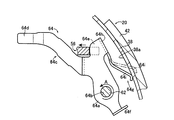
本実施例のドラムブレーキは、実施例1のアジャストレバー54とは異なるアジャストレバー64を備える以外は実施例1のドラムブレーキ10と略同様であり、図5はそのアジャストレバー64を説明する図であり、実施例1の図3に対応するものである。   The drum brake of this embodiment is substantially the same as the drum brake 10 of the first embodiment except that it includes an adjustment lever 64 that is different from the adjustment lever 54 of the first embodiment, and FIG. 5 is a diagram illustrating the adjustment lever 64. Yes, corresponding to FIG. 3 of the first embodiment.

アジャストレバー64は、一枚の板材例えば綱板からプレス加工されることによって図5に示すように成形されており、そのアジャストレバー64の回動中心部64aに貫通された嵌合穴64bに軸部材62が相対回転可能に嵌め入れられることによって、アジャストレバー64はその軸部材62回りに相対回動可能にブレーキシュー20のシューウェブ34に配設されている。   The adjusting lever 64 is formed as shown in FIG. 5 by being pressed from a single plate material such as a steel plate, and the adjusting lever 64 has a shaft in a fitting hole 64b penetrating through the rotation center portion 64a of the adjusting lever 64. By fitting the member 62 so as to be relatively rotatable, the adjusting lever 64 is disposed on the shoe web 34 of the brake shoe 20 so as to be relatively rotatable around the shaft member 62.

また、アジャストレバー64は、図5に示すように、実施例1の延長部54cと同様の機能を有する延長部64cと、実施例1の係合板54dと同様の機能を有する係合板64dと、実施例1の係合部54eと同様の機能を有する係合部64eと、実施例1の抜止め突部54fと同様の機能を有する抜止め突部64fと、そのアジャストレバー64の係合部64eから一体に先端部がブレーキシュー20のシューリム38側に延長されるばね部64gとを一体に備えている。   Further, as shown in FIG. 5, the adjustment lever 64 includes an extension portion 64c having the same function as the extension portion 54c of the first embodiment, an engagement plate 64d having the same function as the engagement plate 54d of the first embodiment, The engaging portion 64e having the same function as the engaging portion 54e of the first embodiment, the retaining projection 64f having the same function as the retaining projection 54f of the first embodiment, and the engaging portion of the adjusting lever 64 64e is integrally provided with a spring part 64g whose tip is extended to the shoe rim 38 side of the brake shoe 20 integrally.

図5に示すように、アジャストレバー64のばね部64gは、そのアジャストレバー64の係合部64eからバッキングプレート16側に曲げられる曲げ部64hと、その曲げ部64hの軸部材62側の側面から先端部がシューリム38の内周面38aと圧接するように延長される板ばね部64iとを一体に備えている。   As shown in FIG. 5, the spring portion 64g of the adjusting lever 64 is bent from the engaging portion 64e of the adjusting lever 64 toward the backing plate 16 side, and from the side surface of the bending portion 64h on the shaft member 62 side. A leaf spring portion 64i that is extended so that the tip portion is in pressure contact with the inner peripheral surface 38a of the shoe rim 38 is integrally provided.

図5の一点鎖線で示す板ばね部64iは、アジャストレバー64がシュー間隙自動調節機構26に組み付けられる前すなわちアジャストレバー64の板ばね部64iに外力が加えられていない状態を示すものである。この図5の一点鎖線の板ばね部64iが示すように、アジャストレバー64がシュー間隙自動調節機構26に組み付けられると板ばね部64iの先端部がブレーキシュー20のシューリム38の内周面38aによって軸部材62に接近する方向にその板ばね部64iが弾性変形させられる。そのため、アジャストレバー64がシュー間隙自動調節機構26に組み付けられると、アジャストレバー64の板ばね部64iは、その板ばね部64iの弾性復帰力によってアジャストレバー64の係合部64eをブレーキシュー18側に軸部材62回りに回動するようにすなわち矢印A方向に回動するように付勢し、第1ストラット部材56すなわちストラット52をそのアジャストレバー64の係合部64eを介してブレーキシュー18側に付勢する。   A leaf spring portion 64i indicated by a one-dot chain line in FIG. 5 indicates a state in which an external force is not applied to the leaf spring portion 64i of the adjustment lever 64 before the adjustment lever 64 is assembled to the shoe gap automatic adjustment mechanism 26. As shown by the one-dot chain line leaf spring portion 64 i in FIG. 5, when the adjusting lever 64 is assembled to the shoe gap automatic adjusting mechanism 26, the distal end portion of the leaf spring portion 64 i is caused by the inner peripheral surface 38 a of the shoe rim 38 of the brake shoe 20. The leaf spring portion 64 i is elastically deformed in a direction approaching the shaft member 62. Therefore, when the adjusting lever 64 is assembled to the shoe gap automatic adjusting mechanism 26, the leaf spring portion 64i of the adjusting lever 64 causes the engaging portion 64e of the adjusting lever 64 to be moved to the brake shoe 18 side by the elastic return force of the leaf spring portion 64i. The first strut member 56, that is, the strut 52 is urged so as to rotate about the shaft member 62, that is, in the direction of arrow A, and the brake shoe 18 side via the engaging portion 64 e of the adjustment lever 64. Energize to.

本実施例のドラムブレーキによれば、アジャストレバー64の回動中心部64aには、ブレーキシュー20のシューウェブ34に突設された軸部材62を相対回転可能に嵌め入れる嵌合穴64bが穿設されており、アジャストレバー64は、その嵌合穴64bに軸部材62が嵌め入れられることによりブレーキシュー20に相対回転可能に配設され、アジャストレバー64のばね部64gは、そのアジャストレバー64の係合部64eから一体に延長されるものである。このため、アジャストレバー64のばね部64gの先端部がブレーキシュー20のシューリム38の内周面38aと圧接させられた力が直接アジャストレバー64の係合部64eに伝達されその力によるアジャストレバー64の軸部材62まわりの力のモーメントが好適に大きくされるので、アジャストレバー64の係合部64eを介して第1ストラット部材56すなわちストラット52をブレーキシュー18側に付勢させる付勢力が好適に向上する。   According to the drum brake of the present embodiment, the rotation center portion 64a of the adjusting lever 64 has the fitting hole 64b into which the shaft member 62 protruding from the shoe web 34 of the brake shoe 20 is fitted so as to be relatively rotatable. The adjusting lever 64 is disposed so as to be rotatable relative to the brake shoe 20 by fitting the shaft member 62 into the fitting hole 64b, and the spring portion 64g of the adjusting lever 64 is provided with the adjusting lever 64. It is extended integrally from the engaging part 64e. For this reason, the force in which the tip of the spring portion 64g of the adjustment lever 64 is brought into pressure contact with the inner peripheral surface 38a of the shoe rim 38 of the brake shoe 20 is directly transmitted to the engaging portion 64e of the adjustment lever 64, and the adjustment lever 64 by that force is transmitted. Since the moment of the force around the shaft member 62 is suitably increased, an urging force for urging the first strut member 56, that is, the strut 52 toward the brake shoe 18 via the engaging portion 64e of the adjusting lever 64 is preferably used. improves.

更に、本発明の他の実施例を説明する。本実施例のドラムブレーキは、実施例1のアジャストレバー54とは異なるアジャストレバー66を備える以外は実施例1のドラムブレーキ10と略同様であって、図6はそのアジャストレバー66を説明する図であり、実施例1の図3に対応するものである。   Further, another embodiment of the present invention will be described. The drum brake of the present embodiment is substantially the same as the drum brake 10 of the first embodiment except that an adjustment lever 66 different from the adjustment lever 54 of the first embodiment is provided, and FIG. 6 is a diagram for explaining the adjustment lever 66. This corresponds to FIG. 3 of the first embodiment.

アジャストレバー66は、一枚の板材例えば綱板からプレス加工されることによって図6に示すように成形されており、そのアジャストレバー66の回動中心部66aに貫通された嵌合穴66bに軸部材62が相対回転可能に嵌め入れられることによって、アジャストレバー66はその軸部材62回りに相対回動可能にブレーキシュー20のシューウェブ34に配設されている。   The adjusting lever 66 is formed as shown in FIG. 6 by being pressed from a single plate material such as a steel plate, and the adjusting lever 66 has a shaft in a fitting hole 66b penetrating through the rotation center 66a of the adjusting lever 66. The adjustment lever 66 is disposed on the shoe web 34 of the brake shoe 20 so as to be rotatable about the shaft member 62 by fitting the member 62 so as to be relatively rotatable.

また、アジャストレバー66は、図6に示すように、実施例1の延長部54cと同様の機能を有する延長部66cと、実施例1の係合板54dと同様の機能を有する係合板66dと、実施例1の係合部54eと同様の機能を有する係合部66eと、実施例1の抜止め突部54fと同様の機能を有する抜止め突部66fと、アジャストレバー66のシューリム38側の端縁における軸部材62に対して係合部66e側の一部の端縁部66gからブレーキシュー20のシューリム38側に先端部が延長されるばね部66hとを一体に備えている。   Further, as shown in FIG. 6, the adjustment lever 66 includes an extension portion 66c having the same function as the extension portion 54c of the first embodiment, an engagement plate 66d having the same function as the engagement plate 54d of the first embodiment, The engaging portion 66e having the same function as the engaging portion 54e of the first embodiment, the retaining projection 66f having the same function as the retaining projection 54f of the first embodiment, and the shoe rim 38 side of the adjustment lever 66 A spring portion 66h whose tip end portion extends from the end edge portion 66g on the engagement portion 66e side to the shoe rim 38 side of the brake shoe 20 with respect to the shaft member 62 at the end edge is integrally provided.

図6に示すように、アジャストレバー66のばね部66hは、そのアジャストレバー66の端縁部66gからバッキングプレート16側に曲げられる曲げ部66iと、その曲げ部66iの係合部66eと反対側の側面から先端部が係合部66eから離間する方向に延長されその後その先端部が係合部66eに接近する方向に円弧状に曲げられてシューリム38の内周面38aと圧接するように延長される板ばね部66jとを一体に備えている。   As shown in FIG. 6, the spring portion 66h of the adjustment lever 66 includes a bent portion 66i bent from the end edge portion 66g of the adjust lever 66 toward the backing plate 16, and an opposite side of the engaging portion 66e of the bent portion 66i. The distal end portion is extended from the side surface of the shoe rim in a direction away from the engaging portion 66e, and then the distal end portion is bent in an arc shape in a direction approaching the engaging portion 66e so as to be in pressure contact with the inner peripheral surface 38a of the shoe rim 38. The leaf spring portion 66j is integrally provided.

図6の一点鎖線で示す板ばね部66jは、アジャストレバー66がシュー間隙自動調節機構26に組み付けられる前すなわちアジャストレバー66の板ばね部66jに外力が加えられていない状態を示すものである。この図6の一点鎖線の板ばね部66jが示すように、アジャストレバー66がシュー間隙自動調節機構26に組み付けられると板ばね部66jの先端部がブレーキシュー20のシューリム38の内周面38aによって係合部66eに接近する方向にその板ばね部66jが弾性変形させられる。そのため、アジャストレバー66がシュー間隙自動調節機構26に組み付けられると、アジャストレバー66の板ばね部66jは、その板ばね部66jの弾性復帰力によってアジャストレバー66の係合部66eをブレーキシュー18側に軸部材62回りに回動するようにすなわち矢印A方向に回動するように付勢し、第1ストラット部材56すなわちストラット52をそのアジャストレバー66の係合部66eを介してブレーキシュー18側に付勢する。   A leaf spring portion 66j indicated by a one-dot chain line in FIG. 6 indicates a state in which no external force is applied to the leaf spring portion 66j of the adjustment lever 66 before the adjustment lever 66 is assembled to the shoe gap automatic adjustment mechanism 26. As shown by the one-dot chain line leaf spring portion 66j in FIG. 6, when the adjusting lever 66 is assembled to the shoe gap automatic adjusting mechanism 26, the tip portion of the leaf spring portion 66j is supported by the inner peripheral surface 38a of the shoe rim 38 of the brake shoe 20. The leaf spring portion 66j is elastically deformed in a direction approaching the engaging portion 66e. Therefore, when the adjusting lever 66 is assembled to the shoe gap automatic adjusting mechanism 26, the leaf spring portion 66j of the adjusting lever 66 causes the engaging portion 66e of the adjusting lever 66 to be moved to the brake shoe 18 side by the elastic return force of the leaf spring portion 66j. The first strut member 56, that is, the strut 52 is urged so as to rotate around the shaft member 62, that is, in the direction of arrow A, and the brake shoe 18 side via the engaging portion 66 e of the adjusting lever 66. Energize to.

本実施例のドラムブレーキによれば、アジャストレバー66は、そのアジャストレバー66に一体に備えられたばね部66hの先端部がブレーキシュー20のシューリム38の内周面38aと圧接させられることによって、そのアジャストレバー66の係合部66eを介して第1ストラット部材56すなわちストラット52をブレーキシュー18側に付勢するので、従来のシュー間隙自動調節機構に備えられたスプリングの機能をアジャストレバー66に追加することができ従来のシュー間隙自動調節機構に比べシュー間隙自動調節機構26の部品点数を削減させることができる。   According to the drum brake of the present embodiment, the adjustment lever 66 is configured such that the tip of the spring portion 66h provided integrally with the adjustment lever 66 is brought into pressure contact with the inner peripheral surface 38a of the shoe rim 38 of the brake shoe 20. Since the first strut member 56, that is, the strut 52 is urged toward the brake shoe 18 via the engaging portion 66 e of the adjustment lever 66, the spring function provided in the conventional shoe clearance automatic adjustment mechanism is added to the adjustment lever 66. Therefore, the number of parts of the shoe gap automatic adjusting mechanism 26 can be reduced as compared with the conventional shoe gap automatic adjusting mechanism.

更に、本発明の他の実施例を説明する。本実施例のドラムブレーキは、実施例1のアジャストレバー54とは異なるアジャストレバー68を備える以外は実施例1のドラムブレーキ10と略同様であって、図7はそのアジャストレバー68を説明する図であり、実施例1の図3に対応するものである。   Further, another embodiment of the present invention will be described. The drum brake of this embodiment is substantially the same as the drum brake 10 of the first embodiment except that it includes an adjustment lever 68 different from the adjustment lever 54 of the first embodiment, and FIG. 7 is a diagram illustrating the adjustment lever 68. This corresponds to FIG. 3 of the first embodiment.

アジャストレバー68は、一枚の板材例えば綱板からプレス加工されることによって図7に示すように成形されており、そのアジャストレバー68の回動中心部68aに貫通された嵌合穴68bに軸部材62が相対回転可能に嵌め入れられることによって、アジャストレバー68はその軸部材62回りに相対回動可能にブレーキシュー20のシューウェブ34に配設されている。   The adjusting lever 68 is formed as shown in FIG. 7 by being pressed from a single plate material, such as a steel plate, and the adjusting lever 68 has a shaft in a fitting hole 68b that penetrates the rotation center portion 68a of the adjusting lever 68. The adjustment lever 68 is disposed on the shoe web 34 of the brake shoe 20 so as to be relatively rotatable around the shaft member 62 by fitting the member 62 so as to be relatively rotatable.

また、アジャストレバー68は、図7に示すように、実施例1の延長部54cと同様の機能を有する延長部68cと、実施例1の係合板54dと同様の機能を有する係合板68dと、実施例1の係合部54eと同様の機能を有する係合部68eと、実施例1の抜止め突部54fと同様の機能を有する抜止め突部68fと、そのアジャストレバー68の係合部68eから一体にブレーキシュー20のシューリム38側に先端部が延長されるばね部68gとを一体に備えている。   Further, as shown in FIG. 7, the adjustment lever 68 includes an extension portion 68c having the same function as the extension portion 54c of the first embodiment, an engagement plate 68d having the same function as the engagement plate 54d of the first embodiment, The engaging portion 68e having the same function as the engaging portion 54e of the first embodiment, the retaining protrusion 68f having the same function as the retaining protrusion 54f of the first embodiment, and the engaging portion of the adjusting lever 68 68e is integrally provided with a spring portion 68g whose tip is extended to the shoe rim 38 side of the brake shoe 20 integrally.

図7に示すように、アジャストレバー68のばね部68gは、そのアジャストレバー68の係合部68eからバッキングプレート16側に曲げられる曲げ部68hと、その曲げ部68hの軸部材62側とは反対側の側面から先端部が軸部材62から離間する方向に延長されその後その先端部が軸部材62に接近する方向に円弧状に曲げられてシューリム38の内周面38aと圧接するように延長される板ばね部68iとを一体に備えている。   As shown in FIG. 7, the spring portion 68g of the adjusting lever 68 is opposite to the bent portion 68h bent from the engaging portion 68e of the adjusting lever 68 to the backing plate 16 side, and the shaft member 62 side of the bent portion 68h. The distal end portion is extended from the side surface in a direction away from the shaft member 62, and then the distal end portion is bent in an arc shape in a direction approaching the shaft member 62 so as to be in pressure contact with the inner peripheral surface 38 a of the shoe rim 38. The leaf spring portion 68i is integrally provided.

図7の一点鎖線で示す板ばね部68iは、アジャストレバー68がシュー間隙自動調節機構26に組み付けられる前すなわちアジャストレバー68の板ばね部68iに外力が加えられていない状態を示すものである。この図7の一点鎖線の板ばね部68iが示すように、アジャストレバー68がシュー間隙自動調節機構26に組み付けられると板ばね部68iの先端部がブレーキシュー20のシューリム38の内周面38aによって軸部材62に接近する方向にその板ばね部68iが弾性変形させられる。そのため、アジャストレバー68がシュー間隙自動調節機構26に組み付けられると、アジャストレバー68の板ばね部68iは、その板ばね部68iの弾性復帰力によってアジャストレバー68の係合部68eをブレーキシュー18側に軸部材62回りに回動するようにすなわち矢印A方向に回動するように付勢し、第1ストラット部材56すなわちストラット52をそのアジャストレバー68の係合部68eを介してブレーキシュー18側に付勢する。   A leaf spring portion 68i indicated by a one-dot chain line in FIG. 7 indicates a state in which an external force is not applied to the leaf spring portion 68i of the adjustment lever 68 before the adjustment lever 68 is assembled to the shoe gap automatic adjustment mechanism 26. As shown by the one-dot chain line leaf spring portion 68i in FIG. The leaf spring portion 68 i is elastically deformed in a direction approaching the shaft member 62. Therefore, when the adjusting lever 68 is assembled to the shoe gap automatic adjusting mechanism 26, the leaf spring portion 68i of the adjusting lever 68 causes the engaging portion 68e of the adjusting lever 68 to be moved to the brake shoe 18 side by the elastic return force of the leaf spring portion 68i. The first strut member 56, that is, the strut 52 is urged so as to rotate about the shaft member 62, that is, in the direction of the arrow A, and the brake shoe 18 side via the engaging portion 68 e of the adjusting lever 68. Energize to.

本実施例のドラムブレーキによれば、アジャストレバー68の回動中心部68aには、ブレーキシュー20のシューウェブ34に突設された軸部材62を相対回転可能に嵌め入れる嵌合穴68bが穿設されており、アジャストレバー68は、その嵌合穴68bに軸部材62が嵌め入れられることによりブレーキシュー20に相対回転可能に配設され、アジャストレバー68のばね部68gは、そのアジャストレバー68の係合部68eから一体に延長されるものである。このため、アジャストレバー68のばね部68gの先端部がブレーキシュー20のシューリム38の内周面38aと圧接させられた力が直接アジャストレバー68の係合部68eに伝達されその力によるアジャストレバー68の軸部材62まわりの力のモーメントが好適に大きくされるので、アジャストレバー68の係合部68eを介して第1ストラット部材56すなわちストラット52をブレーキシュー18側に付勢させる付勢力が好適に向上する。   According to the drum brake of the present embodiment, the rotation center portion 68a of the adjusting lever 68 has the fitting hole 68b into which the shaft member 62 protruding from the shoe web 34 of the brake shoe 20 is fitted so as to be relatively rotatable. The adjusting lever 68 is disposed so as to be rotatable relative to the brake shoe 20 by fitting the shaft member 62 into the fitting hole 68b. The spring portion 68g of the adjusting lever 68 is provided with the adjusting lever 68. It extends integrally from the engaging portion 68e. For this reason, the force that the tip of the spring portion 68g of the adjusting lever 68 is brought into pressure contact with the inner peripheral surface 38a of the shoe rim 38 of the brake shoe 20 is directly transmitted to the engaging portion 68e of the adjusting lever 68, and the adjusting lever 68 by that force is used. Since the moment of the force around the shaft member 62 is preferably increased, an urging force for urging the first strut member 56, that is, the strut 52 toward the brake shoe 18 via the engaging portion 68e of the adjusting lever 68 is preferably used. improves.

以上、本発明の実施例を図面に基づいて説明したが、本発明はその他の態様においても適応される。   As mentioned above, although the Example of this invention was described based on drawing, this invention is applied also in another aspect.

たとえば、本実施例のドラムブレーキにおいて、アジャストレバー54,64,66,68の回動中心部54a,64a,66a,68aにはブレーキシュー20のシューウェブ34に突設された軸部材62を相対回転可能に嵌め入れる嵌合穴54b,64b,66b,68bが穿設されており、その嵌合穴54b,64b,66b,68bを軸部材62に嵌め入れることによってアジャストレバー54,64,66,68はブレーキシュー34に相対回動可能に配設されるものであったが、アジャストレバー54,64,66,68には必ずしも嵌合穴54b,64b,66b,68bが穿設される必要はなく、例えばアジャストレバー54,64,66,68の回動中心部54a,64a,66a,68aに略円筒形状の軸部を突設させブレーキシュー20のシューウェブ34にその軸部を嵌め入れる嵌合穴を穿設させることによって、アジャストレバー54,64,66,68の軸部をシューウェブ34の嵌合穴に嵌め入れてアジャストレバー54,64,66,68をブレーキシュー20のシューウェブ34に相対回動可能に配設させても良い。   For example, in the drum brake of the present embodiment, the pivot member 54a, 64a, 66a, 68a of the adjustment lever 54, 64, 66, 68 is provided with a shaft member 62 projecting from the shoe web 34 of the brake shoe 20 relative to the pivot center 54a, 64a, 66a, 68a. Fitting holes 54 b, 64 b, 66 b, 68 b to be fitted in a rotatable manner are formed, and adjusting levers 54, 64, 66, by fitting the fitting holes 54 b, 64 b, 66 b, 68 b into the shaft member 62. 68 is disposed so as to be rotatable relative to the brake shoe 34, but the adjusting levers 54, 64, 66, 68 are not necessarily provided with fitting holes 54b, 64b, 66b, 68b. For example, a substantially cylindrical shaft portion is projected from the rotation center portions 54a, 64a, 66a, 68a of the adjusting levers 54, 64, 66, 68. A fitting hole for fitting the shaft portion into the shoe web 34 of the rake shoe 20 is formed so that the shaft portions of the adjustment levers 54, 64, 66, 68 are fitted into the fitting holes of the shoe web 34 to adjust the adjustment lever 54. , 64, 66, 68 may be disposed on the shoe web 34 of the brake shoe 20 so as to be relatively rotatable.

また、本実施例のドラムブレーキにおいて、アジャストレバー54,64,66,68は、一枚の綱板をプレス加工によって成形したものであったが、アジャストレバー54,64,66,68は必ずしも綱板から成形される必要はなく、例えば第2ストラット部材58がブレーキシュー18と当接するようにストラット52がブレーキシュー18側に付勢させられる程度にアジャストレバー54,64,66,68のはね部54h,64g,66h,68gが弾性変形できる材質であればどのような板材が使用されても良い。   Further, in the drum brake of this embodiment, the adjustment levers 54, 64, 66, and 68 are formed by pressing a single steel plate by press working, but the adjustment levers 54, 64, 66, and 68 are not necessarily steel ropes. It is not necessary to form the plate, for example, the adjustment levers 54, 64, 66, and 68 are splashed to such an extent that the strut 52 is biased toward the brake shoe 18 so that the second strut member 58 contacts the brake shoe 18. Any plate material may be used as long as the portions 54h, 64g, 66h, and 68g can be elastically deformed.

また、本実施例のドラムブレーキにおいて、アジャストレバー54,64,66,68は、ブレーキペダル操作によって一対のブレーキシュー18,20が拡開しそのばね部54h,64g,66h,68gの付勢力によって係合板54d,64d,66d,68dが矢印B方向に回動して、その係合板54d,64d,66d,68dがアジャストホイール60aの係合歯60eと係合して噛み合いさらに矢印B方向に移動することによってアジャストホイール60aが矢印C方向に回動させられてストラット52が伸長するものであった。すなわち、アジャストレバー54,64,66,68のばね部54h,64g,66h,68gは、そのアジャストレバー54,64,66,68の係合板54d,64d,66d,68dをストラット52が伸長する方向にアジャストホイール60aが回動する矢印C方向(一方向)と同じ方向に回動するように付勢させていたものであった。しかし、例えば、アジャストホイール60aの係合歯60eの歯先を矢印C方向と同じ方向に傾斜させると共にアジャストホイール60aを矢印C方向とは反対方向に回動させるとストラット52が伸長するように設定して、アジャストレバー54,64,66,68の係合板54d,64d,66d,68dがブレーキペダル操作解除時に矢印B方向と反対方向に戻ることによりアジャストホイール60aの係合歯60eと噛み合いアジャストホイール60aが矢印C方向とは反対方向に回動させられストラット52が伸長させられるようにしても良い。すなわち、アジャストレバー54,64,66,68のばね部54h,64g,66h,68gは、そのアジャストレバー54,64,66,68の係合板54d,64d,66d,68dをストラット52が伸長する方向にアジャストホイール60aが回動する方向(一方向)と反対方向に回動するように付勢させても良い。   Further, in the drum brake of this embodiment, the adjusting levers 54, 64, 66, and 68 have the pair of brake shoes 18 and 20 expanded by the operation of the brake pedal, and the biasing force of the spring portions 54h, 64g, 66h, and 68g. The engagement plates 54d, 64d, 66d, and 68d rotate in the direction of arrow B, and the engagement plates 54d, 64d, 66d, and 68d engage with the engagement teeth 60e of the adjustment wheel 60a, and further move in the direction of arrow B. As a result, the adjustment wheel 60a is rotated in the direction of arrow C, and the strut 52 extends. That is, the spring portions 54h, 64g, 66h, 68g of the adjusting levers 54, 64, 66, 68 are directions in which the struts 52 extend the engaging plates 54d, 64d, 66d, 68d of the adjusting levers 54, 64, 66, 68. The adjustment wheel 60a is urged to rotate in the same direction as the arrow C direction (one direction) in which the adjustment wheel 60a rotates. However, for example, the strut 52 is set to extend when the tooth tip of the engagement tooth 60e of the adjustment wheel 60a is inclined in the same direction as the arrow C and the adjustment wheel 60a is rotated in the direction opposite to the arrow C direction. Then, when the engagement plates 54d, 64d, 66d, 68d of the adjustment levers 54, 64, 66, 68 return in the direction opposite to the arrow B direction when the brake pedal operation is released, the engagement wheels 60a of the adjustment wheel 60a mesh with the adjustment teeth 60e. 60a may be rotated in the direction opposite to the arrow C direction so that the strut 52 is extended. That is, the spring portions 54h, 64g, 66h, 68g of the adjusting levers 54, 64, 66, 68 are directions in which the struts 52 extend the engaging plates 54d, 64d, 66d, 68d of the adjusting levers 54, 64, 66, 68. The adjustment wheel 60a may be urged so as to rotate in a direction opposite to the direction in which the adjustment wheel 60a rotates (one direction).

その他一々例示はしないが、本発明は当業者の知識に基づいて種々の変更、改良を加えた態様で実施することができる。   Although not illustrated one by one, the present invention can be implemented in variously modified and improved modes based on the knowledge of those skilled in the art.

10:ドラムブレーキ
12:ブレーキドラム(回転ドラム)
16:バッキングプレート
18,20:一対のブレーキシュー
32,34:シューウェブ
36,38:シューリム
26:シュー間隙自動調節機構
52:ストラット
54,64,66,68:アジャストレバー
54a,64a,66a,68a:回動中心部
54b,64b,66b,68b:嵌合穴
54e,64e,66e,68e:係合部
54h,64g,66h,68g:ばね部
56:第1ストラット部材
58:第2ストラット部材
60:調節軸
60a:アジャストホイール
62:軸部材
10: Drum brake 12: Brake drum (rotating drum)
16: backing plate 18, 20: pair of brake shoes 32, 34: shoe web 36, 38: shoe rim 26: shoe clearance automatic adjustment mechanism 52: struts 54, 64, 66, 68: adjust levers 54a, 64a, 66a, 68a : Rotation center part 54b, 64b, 66b, 68b: fitting hole 54e, 64e, 66e, 68e: engagement part 54h, 64g, 66h, 68g: spring part 56: first strut member 58: second strut member 60 : Adjustment shaft 60a: Adjustment wheel 62: Shaft member

Claims (2)

バッキングプレートに拡開可能に設けられた一対のブレーキシューの一方に係合する第1ストラット部材と、該一対のブレーキシューの他方に係合する第2ストラット部材と、アジャストホイールを備えて該第1ストラット部材と第2ストラット部材との間に配設されて少なくとも一方のストラット部材に螺合する調節軸とを有し、非制動時における該一対のブレーキシューの待機位置を規定するストラットと、制動時における前記一対のブレーキシューの拡開量に応じて回動させられて前記アジャストホイールを一方向に回動させるアジャストレバーとを有し、前記アジャストレバーによって前記アジャストホイールが回動させられることにより前記ストラットが伸長し、非制動時における前記一対のブレーキシューと回転ドラムとの間のシュー間隙を自動的に調節する車両用ドラムブレーキのシュー間隙自動調節機構を備えたドラムブレーキにおいて、
前記アジャストレバーは、一枚の板材からプレス加工されることによって、前記第1ストラット部材と係合する係合部と、該係合部を介して前記第1ストラット部材を前記一対のブレーキシューの他方側に付勢するばね部とを一体に備えており、
前記アジャストレバーのばね部は、先端部が前記ブレーキシューのシューリムの内周面と圧接させられることによって、前記アジャストレバーを前記一方向或いは前記一方向の反対方向に回動するように付勢するものであることを特徴とする車両用ドラムブレーキのシュー間隙自動調節機構を備えたドラムブレーキ。
A first strut member that engages with one of a pair of brake shoes provided on the backing plate so as to be expandable, a second strut member that engages with the other of the pair of brake shoes, and an adjustment wheel are provided. A strut having an adjustment shaft disposed between the one strut member and the second strut member and screwed into at least one strut member, and defining a standby position of the pair of brake shoes during non-braking; An adjusting lever that is rotated according to the amount of expansion of the pair of brake shoes during braking and rotates the adjusting wheel in one direction, and the adjusting wheel is rotated by the adjusting lever. The struts extend due to the gap between the pair of brake shoes and the rotating drum when not braking. In drum brake with automatic automatic shoe clearance adjustment mechanism of a vehicle drum brake for adjusting the-menu gap,
The adjusting lever is press-worked from a single plate material, thereby engaging the first strut member with the first strut member via the engaging portion. It has a spring part that biases to the other side,
The spring portion of the adjustment lever urges the adjustment lever to rotate in the one direction or the opposite direction of the one direction by pressing the tip portion with the inner peripheral surface of the shoe rim of the brake shoe. A drum brake having a shoe gap automatic adjusting mechanism for a vehicle drum brake, characterized by being a thing.
前記アジャストレバーの回動中心部には、前記一対のブレーキシューの一方のシューウェブに突設された軸部材を相対回転可能に嵌め入れる嵌合穴が穿設されており、
前記アジャストレバーは、その嵌合穴に前記軸部材が嵌め入れられることにより前記ブレーキシューに相対回転可能に配設され、
前記アジャストレバーのばね部は、該アジャストレバーの係合部から一体に延長されるものである請求項1の車両用ドラムブレーキのシュー間隙自動調節機構を備えたドラムブレーキ。
A fitting hole into which a shaft member projecting from one shoe web of the pair of brake shoes is fitted so as to be relatively rotatable is formed in a rotation center portion of the adjustment lever,
The adjustment lever is disposed so as to be rotatable relative to the brake shoe by fitting the shaft member into the fitting hole.
The drum brake provided with a shoe gap automatic adjusting mechanism for a vehicle drum brake according to claim 1, wherein the spring portion of the adjust lever is integrally extended from the engaging portion of the adjust lever.
JP2010294148A 2010-12-28 2010-12-28 Drum brake Pending JP2012141012A (en)

Priority Applications (1)

Application Number Priority Date Filing Date Title
JP2010294148A JP2012141012A (en) 2010-12-28 2010-12-28 Drum brake

Applications Claiming Priority (1)

Application Number Priority Date Filing Date Title
JP2010294148A JP2012141012A (en) 2010-12-28 2010-12-28 Drum brake

Publications (1)

Publication Number Publication Date
JP2012141012A true JP2012141012A (en) 2012-07-26

Family

ID=46677476

Family Applications (1)

Application Number Title Priority Date Filing Date
JP2010294148A Pending JP2012141012A (en) 2010-12-28 2010-12-28 Drum brake

Country Status (1)

Country Link
JP (1) JP2012141012A (en)

Cited By (1)

* Cited by examiner, † Cited by third party
Publication number Priority date Publication date Assignee Title
JP2014062621A (en) * 2012-09-24 2014-04-10 Nissin Kogyo Co Ltd Drum brake for vehicle

Citations (4)

* Cited by examiner, † Cited by third party
Publication number Priority date Publication date Assignee Title
JPS6138235A (en) * 1984-07-13 1986-02-24 ケルシー ヘイズ カンパニー automatic brake adjustment mechanism
JPS61112134U (en) * 1984-12-26 1986-07-16
JP2001165207A (en) * 1999-12-03 2001-06-19 Nisshinbo Ind Inc Duo servo type drum brake device
JP2009002416A (en) * 2007-06-20 2009-01-08 Hosei Brake Ind Ltd Drum brake with shoe clearance automatic adjustment mechanism

Patent Citations (4)

* Cited by examiner, † Cited by third party
Publication number Priority date Publication date Assignee Title
JPS6138235A (en) * 1984-07-13 1986-02-24 ケルシー ヘイズ カンパニー automatic brake adjustment mechanism
JPS61112134U (en) * 1984-12-26 1986-07-16
JP2001165207A (en) * 1999-12-03 2001-06-19 Nisshinbo Ind Inc Duo servo type drum brake device
JP2009002416A (en) * 2007-06-20 2009-01-08 Hosei Brake Ind Ltd Drum brake with shoe clearance automatic adjustment mechanism

Cited By (1)

* Cited by examiner, † Cited by third party
Publication number Priority date Publication date Assignee Title
JP2014062621A (en) * 2012-09-24 2014-04-10 Nissin Kogyo Co Ltd Drum brake for vehicle

Similar Documents

Publication Publication Date Title
EP3951207B1 (en) Brake pad arrangement
JP2012141012A (en) Drum brake
JP2009168228A (en) Drum brake
JP4672130B2 (en) Drum brake with automatic shoe clearance adjustment mechanism
JP2010133456A (en) Drum brake equipped with automatic shoe clearance adjusting mechanism
JP6198889B1 (en) Drum brake for vehicles
JP2002168274A (en) Drum brake
US6422362B1 (en) Brake device
JP2014109312A (en) Drum brake
JP4812689B2 (en) Drum brake with shoe clearance automatic adjustment mechanism
JP4746495B2 (en) Drum brake with shoe clearance automatic adjustment mechanism
JP3936690B2 (en) Drum brake device
JP6332934B2 (en) Automatic brake clearance adjustment device for drum brakes
JP2002098176A (en) Drum brake and brake shoe
JP5812787B2 (en) Drum brake with shoe clearance automatic adjustment mechanism
JP6878184B2 (en) Automatic shoe gap adjustment device for vehicle drum brakes
JP4918419B2 (en) Drum brake with shoe clearance automatic adjustment mechanism
JP2013024390A (en) Drum brake
JP2012241757A (en) Drum brake
JP2007092848A (en) Disc brake device
JP2011007270A (en) Drum brake
JP3847378B2 (en) Drum brake device
JP4813429B2 (en) Drum brake device
JP2009097531A (en) Disc brake device
JP2008128466A (en) Drum brake

Legal Events

Date Code Title Description
A621 Written request for application examination

Free format text: JAPANESE INTERMEDIATE CODE: A621

Effective date: 20131017

A977 Report on retrieval

Free format text: JAPANESE INTERMEDIATE CODE: A971007

Effective date: 20140312

A131 Notification of reasons for refusal

Free format text: JAPANESE INTERMEDIATE CODE: A131

Effective date: 20140507

A02 Decision of refusal

Free format text: JAPANESE INTERMEDIATE CODE: A02

Effective date: 20140930