JP2012140759A - Vehicular door lock device - Google Patents
Vehicular door lock device Download PDFInfo
- Publication number
- JP2012140759A JP2012140759A JP2010292330A JP2010292330A JP2012140759A JP 2012140759 A JP2012140759 A JP 2012140759A JP 2010292330 A JP2010292330 A JP 2010292330A JP 2010292330 A JP2010292330 A JP 2010292330A JP 2012140759 A JP2012140759 A JP 2012140759A
- Authority
- JP
- Japan
- Prior art keywords
- connection hole
- door lock
- lock device
- wall
- lever
- Prior art date
- Legal status (The legal status is an assumption and is not a legal conclusion. Google has not performed a legal analysis and makes no representation as to the accuracy of the status listed.)
- Granted
Links
Images


Classifications
-
- E—FIXED CONSTRUCTIONS
- E05—LOCKS; KEYS; WINDOW OR DOOR FITTINGS; SAFES
- E05B—LOCKS; ACCESSORIES THEREFOR; HANDCUFFS
- E05B79/00—Mounting or connecting vehicle locks or parts thereof
- E05B79/10—Connections between movable lock parts
- E05B79/20—Connections between movable lock parts using flexible connections, e.g. Bowden cables
-
- E—FIXED CONSTRUCTIONS
- E05—LOCKS; KEYS; WINDOW OR DOOR FITTINGS; SAFES
- E05B—LOCKS; ACCESSORIES THEREFOR; HANDCUFFS
- E05B85/00—Details of vehicle locks not provided for in groups E05B77/00 - E05B83/00
- E05B85/02—Lock casings
-
- F—MECHANICAL ENGINEERING; LIGHTING; HEATING; WEAPONS; BLASTING
- F16—ENGINEERING ELEMENTS AND UNITS; GENERAL MEASURES FOR PRODUCING AND MAINTAINING EFFECTIVE FUNCTIONING OF MACHINES OR INSTALLATIONS; THERMAL INSULATION IN GENERAL
- F16C—SHAFTS; FLEXIBLE SHAFTS; ELEMENTS OR CRANKSHAFT MECHANISMS; ROTARY BODIES OTHER THAN GEARING ELEMENTS; BEARINGS
- F16C1/00—Flexible shafts; Mechanical means for transmitting movement in a flexible sheathing
- F16C1/10—Means for transmitting linear movement in a flexible sheathing, e.g. "Bowden-mechanisms"
- F16C1/12—Arrangements for transmitting movement to or from the flexible member
- F16C1/14—Construction of the end-piece of the flexible member; Attachment thereof to the flexible member
-
- F—MECHANICAL ENGINEERING; LIGHTING; HEATING; WEAPONS; BLASTING
- F16—ENGINEERING ELEMENTS AND UNITS; GENERAL MEASURES FOR PRODUCING AND MAINTAINING EFFECTIVE FUNCTIONING OF MACHINES OR INSTALLATIONS; THERMAL INSULATION IN GENERAL
- F16C—SHAFTS; FLEXIBLE SHAFTS; ELEMENTS OR CRANKSHAFT MECHANISMS; ROTARY BODIES OTHER THAN GEARING ELEMENTS; BEARINGS
- F16C2350/00—Machines or articles related to building
- F16C2350/52—Locks, e.g. cables to actuate door locks
Abstract
Description
本発明は、車両用ドアロック装置に関する。 The present invention relates to a vehicle door lock device.
車両用ドアロック装置の一つとして、アウターチューブとインナーワイヤとを有する操作ケーブルと、前記アウターチューブの端部に組付けられるケーブルキャップの支持部を有するハウジングと、前記インナーワイヤの端部に固着された連結具が連結される連結孔を有して前記ハウジングに回転可能に組付けられる回転レバーを備えているものがあり、例えば、下記特許文献1に示されている。また、操作力を伝達するためのロッドと回転レバーを備えていて、ロッドの先端部がクランク状に形成され、この先端部が前記回転レバーに設けた連結孔(係合孔)に挿通されて保持されているものがあり、例えば、下記特許文献2に示されている。 As one of vehicle door lock devices, an operation cable having an outer tube and an inner wire, a housing having a support portion of a cable cap assembled to an end portion of the outer tube, and an end portion of the inner wire are fixed. For example, the following Patent Document 1 discloses a rotating lever that has a connecting hole to which the connected connecting tool is connected and is rotatably assembled to the housing. In addition, a rod for transmitting operating force and a rotating lever are provided, and the tip of the rod is formed in a crank shape, and the tip is inserted into a connecting hole (engagement hole) provided in the rotating lever. For example, it is shown in Patent Document 2 below.
(発明が解決しようとする課題)
上記した特許文献1に記載されている車両用ドアロック装置においては、インナーワイヤの端部に固着された連結具が円柱状に形成されていて中間部外周にてインナーワイヤの端部に固着されており、回転レバーの先端部には折り返し部が形成されていて、この折り返し部に円柱状の連結具を組付けるためのスリット(インナーワイヤを挿通するためのもの)と連結孔(連結具の端部が固定される部位)が形成されている。このため、回転レバーの形状が簡素化できないものの、円柱状の連結具が連結孔に嵌合するように構成すれば、連結具と連結孔(回転レバー)との連結部でのガタツキ(連結孔の径方向でのガタツキ)を無くすことが可能である。
(Problems to be solved by the invention)
In the vehicle door lock device described in Patent Document 1 described above, the coupling member fixed to the end portion of the inner wire is formed in a columnar shape, and is fixed to the end portion of the inner wire at the outer periphery of the intermediate portion. The rotary lever has a folded portion at the tip, and a slit (for inserting the inner wire) and a coupling hole (for coupling the coupling tool) for assembling the cylindrical coupling tool to the folded portion. The site | part to which an edge part is fixed is formed. For this reason, although the shape of the rotating lever cannot be simplified, if the cylindrical connecting tool is configured to fit into the connecting hole, rattling (the connecting hole) at the connecting portion between the connecting tool and the connecting hole (rotating lever). Can be eliminated.
一方、上記した特許文献2に記載されているロッドと回転レバーの結合構造では、回転レバーに折り返し部を設ける必要がないものの、回転レバーの板厚方向(連結孔の軸方向)にてロッドが移動しないようにするためのループ状弾性舌片が回転レバーに設けられていて、回転レバーの形状が簡素化できない。また、この結合構造では、ロッドの先端部がクランク状に形成されるとともに、連結孔が回転レバーの平板部位の形成されているため、連結孔に挿通されるロッドの先端部(クランク状に形成されている部位の中間部)と連結孔の内壁間に所望の隙間が必要であり、ロッドと連結孔(回転レバー)との連結部でのガタツキ(連結孔の径方向でのガタツキ)を無くすことはできない。 On the other hand, in the joint structure of the rod and the rotary lever described in Patent Document 2 described above, although it is not necessary to provide a turn-up portion on the rotary lever, the rod does not move in the plate thickness direction of the rotary lever (the axial direction of the connecting hole). A loop-like elastic tongue for preventing movement is provided on the rotary lever, and the shape of the rotary lever cannot be simplified. Further, in this coupling structure, the tip of the rod is formed in a crank shape, and the connecting hole is formed as a flat plate portion of the rotary lever, so the tip of the rod inserted into the connecting hole (formed in the shape of a crank) A desired gap is required between the intermediate part of the part being connected) and the inner wall of the connecting hole, eliminating backlash at the connecting part between the rod and the connecting hole (rotating lever) (backlash in the radial direction of the connecting hole). It is not possible.
(課題を解決するための手段)
本発明は、上記した課題を解決すべく(回転レバーの形状を簡素化するとともに、連結具と連結孔(回転レバー)との連結部でのガタツキを無くすべく)なされたものであり、アウターチューブとインナーワイヤとを有する操作ケーブルと、前記アウターチューブの端部に組付けられるケーブルキャップの支持部を有するハウジングと、前記インナーワイヤの端部に固着された連結具が連結される連結孔を有して前記ハウジングに回転可能に組付けられる回転レバーを備えている車両用ドアロック装置であって、前記連結孔が前記回転レバーに形成した段部に設けられていて、前記連結具の先端部が前記連結孔に挿通されて保持されており、前記先端部には、前記段部の一側にある前記連結孔の一側内壁に係合するとともに前記回転レバーの一側面に係合する第1屈曲部と、前記段部の他側にある前記連結孔の他側内壁に係合するとともに前記回転レバーの他側面に係合する第2屈曲部が設けられていることに特徴がある。
(Means for solving the problem)
The present invention has been made to solve the above-mentioned problems (in order to simplify the shape of the rotating lever and eliminate rattling at the connecting portion between the connecting tool and the connecting hole (rotating lever)). And an operation cable having an inner wire, a housing having a support portion for a cable cap assembled to the end of the outer tube, and a connection hole for connecting a connector fixed to the end of the inner wire. A vehicle door lock device having a rotation lever that is rotatably assembled to the housing, wherein the connection hole is provided in a step portion formed in the rotation lever, and the distal end portion of the connection tool Is inserted and held in the connecting hole, and the front end portion engages with one side inner wall of the connecting hole on one side of the stepped portion and the rotation lever. A first bent portion that engages with the side surface and a second bent portion that engages with the other inner wall of the connecting hole on the other side of the stepped portion and engages with the other side surface of the rotating lever are provided. There is a special feature.
この場合において、前記第2屈曲部はその前記連結孔の一側内壁側に位置する部位に、前記連結孔の一側内壁と当接して前記連結孔に対する前記先端部の組付けをガイドするように構成された曲面、又は、前記連結孔の一側内壁と干渉しないように構成された曲面を有することも可能である。これらの場合において、前記連結具の基端部に回り止め用の係合部(例えば、突起)が設けられるとともに、前記ケーブルキャップの先端部に前記係合部(例えば、突起)が嵌合可能な係止部(例えば、凹部)が設けられていることも可能である。 In this case, the second bent portion is in contact with the one side inner wall of the connection hole at a portion located on the one side inner wall side of the connection hole so as to guide the assembly of the tip portion with respect to the connection hole. It is also possible to have a curved surface constructed in such a manner that it does not interfere with one side inner wall of the connecting hole. In these cases, an engaging portion (for example, a protrusion) for preventing rotation is provided at the base end portion of the connector, and the engaging portion (for example, a protrusion) can be fitted to the distal end portion of the cable cap. It is also possible that a simple locking part (for example, a concave part) is provided.
(発明の作用効果)
本発明による車両用ドアロック装置においては、連結孔が回転レバーに形成した段部に設けられ、連結具の先端部には、前記段部の一側にある前記連結孔の一側内壁に係合するとともに前記回転レバーの一側面に係合する第1屈曲部と、前記段部の他側にある前記連結孔の他側内壁に係合するとともに前記回転レバーの他側面に係合する第2屈曲部が設けられている。この構成は、連結具における先端部の形状を適宜に設定するとともに、回転レバーにおける段部の板厚方向長さ(段差)を適宜に設定することにより、可能である。
(Effects of the invention)
In the vehicle door lock device according to the present invention, the connection hole is provided in the step portion formed in the rotation lever, and the distal end portion of the connection tool is engaged with the inner wall on one side of the connection hole on one side of the step portion. And a first bent portion that engages with one side surface of the rotating lever, and a second bent portion that engages with the other inner wall of the connecting hole on the other side of the stepped portion and engages with the other side surface of the rotating lever. Two bends are provided. This configuration is possible by appropriately setting the shape of the tip portion of the coupling tool and appropriately setting the plate thickness direction length (step) of the rotating lever.
このため、本発明では、回転レバーには段部を設定することで実施できて、回転レバーの先端部に折り返し部を形成する場合(上記特許文献1の場合)や、回転レバーにループ状弾性舌片を設ける場合(上記特許文献2の場合)に比して、回転レバーの形状を簡素化することが可能である。また、本発明では、連結具の先端部に、上記した第1屈曲部と第2屈曲部が設けられているため、連結具と連結孔(回転レバー)との連結部でのガタツキ(連結孔の径方向でのガタツキと連結孔の軸方向でのガタツキ)を無くすことが可能であり、ガタによる不具合(異音発生、操作ケーブルの作動不良)を防止することが可能である。また、本発明では、アウターチューブとインナーワイヤとを有する操作ケーブルが採用されているため、配索の自由度が大きくて、操作ケーブルを容易に配置することが可能である。 For this reason, in this invention, it can implement by setting a step part in a rotation lever, and when forming a folding | turning part in the front-end | tip part of a rotation lever (in the case of the said patent document 1), loop-like elasticity is provided in a rotation lever. Compared with the case where a tongue piece is provided (in the case of Patent Document 2 above), the shape of the rotary lever can be simplified. In the present invention, since the first bent portion and the second bent portion described above are provided at the distal end portion of the connecting tool, rattling (connecting hole) at the connecting portion between the connecting tool and the connecting hole (rotating lever). It is possible to eliminate the backlash in the radial direction and the backlash in the axial direction of the connecting hole, and it is possible to prevent problems due to backlash (occurrence of abnormal noise, operation cable malfunction). In the present invention, since an operation cable having an outer tube and an inner wire is employed, the degree of freedom in routing is large, and the operation cable can be easily arranged.
また、本発明の実施に際して、前記第2屈曲部が、その前記連結孔の一側内壁側に位置する部位に、前記連結孔の一側内壁と当接して前記連結孔に対する前記先端部の組付けをガイドするように構成された曲面、又は、前記連結孔の一側内壁と干渉しないように構成された曲面を有する場合には、前記連結孔に対して前記先端部を組付ける際の組付け性が向上する。また、本発明の実施に際して、前記連結具の基端部に回り止め用の係合部(例えば、突起)が設けられるとともに、前記ケーブルキャップの先端部に前記係合部(例えば、突起)が嵌合可能な係止部(例えば、凹部)が設けられている場合には、連結具の連結孔(回転レバー)への組付に際して、回り止め用の係合部を係止部に嵌合することで、アウターチューブとインナーワイヤの相対回転を規制できて、連結具の連結孔(回転レバー)への組付性を向上させることが可能である。 Further, when the present invention is implemented, the second bent portion is in contact with the one side inner wall of the connection hole at a portion located on the one side inner wall side of the connection hole, and the set of the tip portion with respect to the connection hole A set for assembling the tip portion with respect to the connecting hole when it has a curved surface configured to guide attachment or a curved surface configured not to interfere with one side inner wall of the connecting hole The attachment is improved. Further, in carrying out the present invention, an engagement portion (for example, a protrusion) for preventing rotation is provided at the base end portion of the connector, and the engagement portion (for example, the protrusion) is provided at the distal end portion of the cable cap. When a locking part (for example, a concave part) that can be fitted is provided, when the coupling tool is assembled to the coupling hole (rotating lever), the locking part is fitted to the locking part. By doing so, it is possible to restrict the relative rotation of the outer tube and the inner wire, and it is possible to improve the assembling property of the coupler to the coupling hole (rotating lever).
以下に、本発明の一実施形態を図面に基づいて説明する。図1および図2は本発明による車両用ドアロック装置100を示していて、この車両用ドアロック装置100は、車両の前方右側に装備されるドア(図示省略)に装着されるものであり、ラッチ機構10とロック機構20を備えている。この車両用ドアロック装置100では、ロック機構20の樹脂ハウジング21に対してラッチ機構10の樹脂ボディ11が固定されることで、ラッチ機構10がロック機構20に組付けられるように構成されている。
Hereinafter, an embodiment of the present invention will be described with reference to the drawings. 1 and 2 show a vehicle
ラッチ機構10は、周知のように、車両のドアをボディ(図示省略の車体)に対して閉状態(ドアが閉じられた状態)で保持するためのもので、上記した樹脂ボディ11を備えるとともに、車体に固定されたストライカ(図示省略)と係脱可能なラッチ12を備えている。ロック機構20は、上記した樹脂ハウジング21を備えるとともに、樹脂ハウジング21に開閉可能に組付けた樹脂カバー22と、樹脂ハウジング21に支持孔23a(図3参照)にて回転可能に組付けられる回転レバー(インサイドオープンレバー)23と、アウターチューブ24aとインナーワイヤ24bとを有する操作ケーブル24を備えている。
As is well known, the
この実施形態において、ラッチ機構10の内部構成(樹脂ボディ11内の内部構成)は、特願2010−251512の車両用ドアロック装置におけるラッチ機構の内部構成と実質的に同じであり、また、ロック機構20の内部構成(樹脂ハウジング21内の内部構成)は、特願2010−251512の車両用ドアロック装置におけるロック機構の内部構成と実質的に同じである。 In this embodiment, the internal structure of the latch mechanism 10 (internal structure in the resin body 11) is substantially the same as the internal structure of the latch mechanism in the vehicle door lock device of Japanese Patent Application No. 2010-251512, and the lock The internal structure of the mechanism 20 (internal structure in the resin housing 21) is substantially the same as the internal structure of the lock mechanism in the vehicle door lock device of Japanese Patent Application No. 2010-251512.
また、この実施形態においては、アウターチューブ24aの端部に筒状のケーブルキャップ24cが一体的に組付けられていて、このケーブルキャップ24cは樹脂ハウジング21の支持部21aに長手方向にて移動不能に組付けられている。一方、インナーワイヤ24bの端部には連結具24dが一体的に固着されていて、この連結具24dは回転レバー23に設けた連結孔23b(図3〜図5参照)に連結されている。
In this embodiment, a
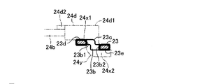
ところで、この実施形態においては、図4および図5に示したように、連結具24dの先端部24d1がクランク状に形成され、図3に示したように、連結孔23bが回転レバー23に形成した段部23cに重なるように設けられていて、連結具24dの先端部24d1が連結孔23bに挿通されて保持されている。回転レバー23に形成した段部23cは、図3に示したように、L字状に設けられていて、連結孔23bが設けられている部位では、支持孔23aの中心と連結孔23bの中心を結ぶ直線に沿って直線状に形成されている。
By the way, in this embodiment, as shown in FIGS. 4 and 5, the tip 24d1 of the
また、連結具24dの先端部24d1には、段部23cの一側(図4の左側)にある連結孔23bの一側内壁23b1に係合するとともに回転レバー23の一側面(図4の上側面)23dに係合する第1屈曲部24x1と、段部23cの他側(図4の右側)にある連結孔23bの他側内壁23b2に係合するとともに回転レバー23の他側面(図4の下側面)23eに係合する第2屈曲部24x2が設けられている。また、この実施形態では、図4および図5に示したように、連結具24dの連結孔(回転レバー)23bへの組付に際して、連結具24dの先端部24d1が連結孔23bの一側内壁23b1と当接して連結孔23bに対する先端部24d1の組付けがガイドされるように(または、先端部24d1が連結孔23bの一側内壁23b1に干渉しないように)、先端部24d1の一部24y(連結孔23bに挿通される部位)が円弧形状(曲面)に形成されている。この一部(曲面)24yは、第2屈曲部24x2における連結孔23bの一側内壁23b1側に位置する部位に設けられている。
Further, the distal end 24d1 of the
また、この実施形態においては、図2に示したように、連結具24dの基端部に回り止め用の突起(係合部)24d2が設けられるとともに、ケーブルキャップ24cの先端部内周に前記突起(係合部)24d2が嵌合可能な凹部(係止部)24c1が設けられている。また、樹脂ハウジング21に規制突起21bが設けられていて、樹脂ハウジング21の開口が樹脂カバー22によって閉じられるまでは、規制突起21bによって回転レバー23が支持孔23a周りの回転を規制されるように構成されている。なお、規制突起21bは、樹脂ハウジング21の開口が樹脂カバー22によって閉じられるとき、樹脂カバー22に設けた押動突起22aによって折損されるように構成されている。
Further, in this embodiment, as shown in FIG. 2, a protrusion (engaging portion) 24d2 for preventing rotation is provided at the base end portion of the
上記のように構成したこの実施形態の車両用ドアロック装置100においては、回転レバー23の連結孔23bが回転レバー23に形成した段部23cに設けられ、連結具24dの先端部24d1には、上記した第1屈曲部24x1と、上記した第2屈曲部24x2が設けられている。この構成は、連結具24dにおける先端部24d1の形状を適宜に設定するとともに、回転レバー23における段部23cの板厚方向長さ(段差)を適宜に設定することにより、可能である。
In the vehicle
このため、この実施形態では、回転レバー23には段部23cを設定することで実施できて、回転レバーの先端部に折り返し部を形成する場合(上記特許文献1の場合)や、回転レバーにループ状弾性舌片を設ける場合(上記特許文献2の場合)に比して、回転レバー23の形状を簡素化することが可能である。また、この実施形態では、連結具24dの先端部24d1に、上記した第1屈曲部24x1と第2屈曲部24x2が設けられているため、連結具24dと連結孔(回転レバー)23bとの連結部でのガタツキ(連結孔23bの径方向(図4の左右方向)でのガタツキと連結孔23bの軸方向(図4の上下方向)でのガタツキ)を無くすことが可能であり、ガタによる不具合(異音発生、操作ケーブル24の作動不良)を防止することが可能である。また、この実施形態では、アウターチューブ24aとインナーワイヤ24bとを有する操作ケーブル24が採用されているため、配索の自由度が大きくて、操作ケーブル24を容易に配置することが可能である。
For this reason, in this embodiment, the
また、この実施形態では、連結具24dの第2屈曲部24x2が、その連結孔23bの一側内壁23b1側に位置する部位に、上記した曲面24yを有しているため、連結孔23bに対して連結具24dの先端部24d1を組付ける際の組付け性が向上する。また、この実施形態では、連結具24dの基端部に回り止め用の突起24d2が設けられるとともに、ケーブルキャップ24cの先端部に突起24d2が嵌合可能な凹部24c1が設けられている。このため、連結具24dの連結孔(回転レバー)23bへの組付に際して、回り止め用の突起24d2を凹部24c1に嵌合することで、アウターチューブ24aとインナーワイヤ24bの相対回転を規制できて、連結具24dの連結孔(回転レバー)23bへの組付性を向上させることが可能である。なお、連結具24dの連結孔(回転レバー)23bへの組付は、図5の(a)の状態から(b)の状態を経て(c)の状態とすることにより行われている。
Further, in this embodiment, the second bent portion 24x2 of the
上記実施形態においては、連結具24dの基端部に回り止め用の突起(係合部)24d2が設けられるとともに、ケーブルキャップ24cの先端部内周に前記突起(係合部)24d2が嵌合可能な凹部(係止部)24c1が設けられているが、連結具(24d)の基端部に回り止め用の凹部(係合部)が設けられるとともに、ケーブルキャップ(24c)の先端部に前記凹部(係合部)が嵌合可能な突起(係止部)が設けられるようにして実施することも可能である。
In the above-described embodiment, a rotation-preventing projection (engagement portion) 24d2 is provided at the base end portion of the
また、上記実施形態においては、回転レバー23に形成した段部23cが支持孔23aの近傍にまで延びるように設けて実施したが、この段部23cは連結孔23bと重なる程度の大きさであればよく、上記実施形態に比して短く設けて実施することも可能である。また、上記した段部23cは連結孔23bと重なる程度の大きさであればよいため、支持孔(23a)が形成されている部位に対して、連結孔(23b)が形成されている部位が折れ曲がるように、回転レバー(23)がL字状に形成されている場合には、連結孔(23b)が形成されている部位(折れ曲がる部位)のみに段部(23c)を設けて実施することも可能である。
In the above embodiment, the
100…車両用ドアロック装置、10…ラッチ機構、11…樹脂ボディ、12…ラッチ、20…ロック機構、21…樹脂ハウジング、21a…支持部、21b…規制突起、22…樹脂カバー、22a…押動突起、23…回転レバー、23a…支持孔、23b…連結孔、23b1…連結孔の一側内壁、23b2…連結孔の他側内壁、23c…段部、23d…回転レバーの一側面、23e…回転レバーの他側面、24…操作ケーブル、24a…アウターチューブ、24b…インナーワイヤ、24c…ケーブルキャップ、24c1…ケーブルキャップに設けた凹部(係止部)、24d…連結具、24d1…連結具の先端部、24x1…連結具の第1屈曲部、24x2…連結具の第2屈曲部、24d2…連結具の基端部に設けた回り止め用の突起(係合部)
DESCRIPTION OF
Claims (3)
前記アウターチューブの端部に組付けられるケーブルキャップの支持部を有するハウジングと、
前記インナーワイヤの端部に固着された連結具が連結される連結孔を有して前記ハウジングに回転可能に組付けられる回転レバーを備えている車両用ドアロック装置であって、
前記連結孔が前記回転レバーに形成した段部に設けられていて、前記連結具の先端部が前記連結孔に挿通されて保持されており、前記先端部には、前記段部の一側にある前記連結孔の一側内壁に係合するとともに前記回転レバーの一側面に係合する第1屈曲部と、前記段部の他側にある前記連結孔の他側内壁に係合するとともに前記回転レバーの他側面に係合する第2屈曲部が設けられている車両用ドアロック装置。 An operation cable having an outer tube and an inner wire;
A housing having a support portion of a cable cap assembled to an end portion of the outer tube;
A vehicle door lock device including a rotation lever rotatably connected to the housing having a connection hole to which a connector fixed to an end of the inner wire is connected,
The connection hole is provided in a step portion formed in the rotating lever, and a tip end portion of the connection tool is inserted and held in the connection hole, and the tip end portion is provided on one side of the step portion. A first bent portion that engages with one side inner wall of the connection hole and a side surface of the rotary lever, and engages with the other side inner wall of the connection hole on the other side of the step portion and the A vehicle door lock device provided with a second bent portion that engages with the other side surface of the rotary lever.
前記第2屈曲部はその前記連結孔の一側内壁側に位置する部位に、前記連結孔の一側内壁と当接して前記連結孔に対する前記先端部の組付けをガイドするように構成された曲面、又は、前記連結孔の一側内壁と干渉しないように構成された曲面を有する車両用ドアロック装置。 The vehicle door lock device according to claim 1,
The second bent portion is configured to be in contact with the inner wall on one side of the connection hole and guide the assembly of the tip portion to the connection hole at a portion located on the inner wall side of the connection hole. A vehicle door lock device having a curved surface or a curved surface configured not to interfere with one side inner wall of the connection hole.
前記連結具の基端部に回り止め用の係合部が設けられるとともに、前記ケーブルキャップの先端部に前記係合部が嵌合可能な係止部が設けられている車両用ドアロック装置。
In the vehicle door lock device according to claim 1 or 2,
A vehicle door lock device in which an engagement portion for preventing rotation is provided at a base end portion of the connector, and a locking portion to which the engagement portion can be fitted is provided at a distal end portion of the cable cap.
Priority Applications (3)
| Application Number | Priority Date | Filing Date | Title |
|---|---|---|---|
| JP2010292330A JP5668468B2 (en) | 2010-12-28 | 2010-12-28 | Vehicle door lock device |
| PCT/JP2011/073757 WO2012090574A1 (en) | 2010-12-28 | 2011-10-07 | Vehicle door lock device |
| CN201190000946.8U CN203383611U (en) | 2010-12-28 | 2011-10-07 | Vehicle door lock device |
Applications Claiming Priority (1)
| Application Number | Priority Date | Filing Date | Title |
|---|---|---|---|
| JP2010292330A JP5668468B2 (en) | 2010-12-28 | 2010-12-28 | Vehicle door lock device |
Publications (2)
| Publication Number | Publication Date |
|---|---|
| JP2012140759A true JP2012140759A (en) | 2012-07-26 |
| JP5668468B2 JP5668468B2 (en) | 2015-02-12 |
Family
ID=44863189
Family Applications (1)
| Application Number | Title | Priority Date | Filing Date |
|---|---|---|---|
| JP2010292330A Expired - Fee Related JP5668468B2 (en) | 2010-12-28 | 2010-12-28 | Vehicle door lock device |
Country Status (3)
| Country | Link |
|---|---|
| JP (1) | JP5668468B2 (en) |
| CN (1) | CN203383611U (en) |
| WO (1) | WO2012090574A1 (en) |
Families Citing this family (4)
| Publication number | Priority date | Publication date | Assignee | Title |
|---|---|---|---|---|
| DE102011010175A1 (en) * | 2011-02-02 | 2012-08-02 | Kiekert Ag | Motor vehicle lock and manufacturing process |
| JP6187014B2 (en) * | 2013-08-09 | 2017-08-30 | アイシン精機株式会社 | Vehicle door lock device |
| JP6368951B2 (en) * | 2014-03-13 | 2018-08-08 | 三井金属アクト株式会社 | Vehicle door latch device |
| JP6379438B2 (en) * | 2014-10-28 | 2018-08-29 | 三井金属アクト株式会社 | Vehicle door latch device |
Citations (1)
| Publication number | Priority date | Publication date | Assignee | Title |
|---|---|---|---|---|
| JP2010174583A (en) * | 2009-02-02 | 2010-08-12 | Mitsui Mining & Smelting Co Ltd | Cable connecting structure |
Family Cites Families (6)
| Publication number | Priority date | Publication date | Assignee | Title |
|---|---|---|---|---|
| DE2014714B2 (en) * | 1970-03-26 | 1972-02-10 | Adam Opel AG, 6090 Russeisheim | JOINT CONNECTION BETWEEN AN ACTUATOR AND A BOWDEN CABLE |
| JPS6159759U (en) | 1984-09-14 | 1986-04-22 | ||
| JP4641122B2 (en) | 2001-07-31 | 2011-03-02 | アイシン精機株式会社 | Automotive door lock assembly |
| EP1849940B1 (en) * | 2006-04-27 | 2016-10-12 | Kiekert Aktiengesellschaft | Locking device for a sliding door with means for blocking the door in open position |
| JP2008041829A (en) | 2006-08-03 | 2008-02-21 | Renesas Technology Corp | Semiconductor device manufacturing method and semiconductor manufacturing device |
| JP5271143B2 (en) | 2009-04-15 | 2013-08-21 | 株式会社竹中工務店 | Magnetic shield body and rectangular tube body thereof |
-
2010
- 2010-12-28 JP JP2010292330A patent/JP5668468B2/en not_active Expired - Fee Related
-
2011
- 2011-10-07 CN CN201190000946.8U patent/CN203383611U/en not_active Expired - Fee Related
- 2011-10-07 WO PCT/JP2011/073757 patent/WO2012090574A1/en active Application Filing
Patent Citations (1)
| Publication number | Priority date | Publication date | Assignee | Title |
|---|---|---|---|---|
| JP2010174583A (en) * | 2009-02-02 | 2010-08-12 | Mitsui Mining & Smelting Co Ltd | Cable connecting structure |
Also Published As
| Publication number | Publication date |
|---|---|
| CN203383611U (en) | 2014-01-08 |
| WO2012090574A1 (en) | 2012-07-05 |
| JP5668468B2 (en) | 2015-02-12 |
Similar Documents
| Publication | Publication Date | Title |
|---|---|---|
| JP5146620B2 (en) | Vehicle door fixing device | |
| JP5668468B2 (en) | Vehicle door lock device | |
| JP6379438B2 (en) | Vehicle door latch device | |
| JP2008027787A (en) | Lever-type connector | |
| JP2014061781A (en) | Latch device for vehicle | |
| WO2017078121A1 (en) | Locking apparatus | |
| JP2017154720A (en) | Housing unit and locking device for opening/closing body | |
| JP2014023334A (en) | Electric wire cabling device | |
| JP5520112B2 (en) | Vehicle locking device, vehicle lid locking device, and vehicle door locking device | |
| JP2015133175A (en) | Charge connector holder | |
| JP2009275371A (en) | Automobile door | |
| JP2018091109A (en) | Lid opening-closing device | |
| JP5634807B2 (en) | Power supply device | |
| JP5227233B2 (en) | LIF connector | |
| JP4335102B2 (en) | Lever fitting type connector | |
| JP2007274882A (en) | Feeding unit | |
| JP5613483B2 (en) | Fuel tank nipple device | |
| JP2013224544A (en) | Vehicle door structure | |
| JP2019002258A (en) | Outer handle device for vehicle door | |
| JP2012089302A (en) | Lever type connector | |
| JP5972023B2 (en) | Locking device | |
| JP5622316B2 (en) | Lever type connector | |
| JP2005076363A (en) | Lock device of vehicle opening and closing part | |
| KR100844415B1 (en) | Handle assembly for opening hood panel | |
| JP7179606B2 (en) | Electric actuator and door latch device |
Legal Events
| Date | Code | Title | Description |
|---|---|---|---|
| A621 | Written request for application examination |
Free format text: JAPANESE INTERMEDIATE CODE: A621 Effective date: 20130322 |
|
| A131 | Notification of reasons for refusal |
Free format text: JAPANESE INTERMEDIATE CODE: A131 Effective date: 20140520 |
|
| A521 | Written amendment |
Free format text: JAPANESE INTERMEDIATE CODE: A523 Effective date: 20140718 |
|
| TRDD | Decision of grant or rejection written | ||
| A01 | Written decision to grant a patent or to grant a registration (utility model) |
Free format text: JAPANESE INTERMEDIATE CODE: A01 Effective date: 20141118 |
|
| A61 | First payment of annual fees (during grant procedure) |
Free format text: JAPANESE INTERMEDIATE CODE: A61 Effective date: 20141201 |
|
| R151 | Written notification of patent or utility model registration |
Ref document number: 5668468 Country of ref document: JP Free format text: JAPANESE INTERMEDIATE CODE: R151 |
|
| LAPS | Cancellation because of no payment of annual fees |