JP2012140382A - Method of synthesizing methane from carbon dioxane and hydrogen - Google Patents
Method of synthesizing methane from carbon dioxane and hydrogen Download PDFInfo
- Publication number
- JP2012140382A JP2012140382A JP2011000451A JP2011000451A JP2012140382A JP 2012140382 A JP2012140382 A JP 2012140382A JP 2011000451 A JP2011000451 A JP 2011000451A JP 2011000451 A JP2011000451 A JP 2011000451A JP 2012140382 A JP2012140382 A JP 2012140382A
- Authority
- JP
- Japan
- Prior art keywords
- reaction
- hydrogen
- reaction step
- carbon dioxide
- methane
- Prior art date
- Legal status (The legal status is an assumption and is not a legal conclusion. Google has not performed a legal analysis and makes no representation as to the accuracy of the status listed.)
- Granted
Links
Images


Landscapes
- Organic Low-Molecular-Weight Compounds And Preparation Thereof (AREA)
Abstract
Description
本発明は二酸化炭素と水素を原料としてメタンを合成する方法に係り、特に、2段階の素反応に分離した反応工程を経て、最終的にメタンを合成する方法に関する。 The present invention relates to a method of synthesizing methane using carbon dioxide and hydrogen as raw materials, and more particularly to a method of finally synthesizing methane through a reaction process separated into two-stage elementary reactions.
従来、地球温暖化問題の解決のために二酸化炭素の固定化を目的として、二酸化炭素と水素を反応させてメタンを合成する技術が種々提案されている(例えば特許文献1乃至5)。
文献1は、触媒としてロジウム(Rh)を用いることを特徴とし、選択的にメタンを合成可能とするものである。この場合の水素と二酸化炭素の反応モル比は、2−4が好ましいとしている。
文献2は、希土類金属を含む金属間化合物を触媒とすることを特徴とし、反応温度及び圧力が比較的低い条件でも有効な収率でメタンを合成可能としている。この場合の水素と二酸化炭素の反応モル比は、特に限定していないが、2−8、好ましくは3−6、特に好ましくは4を推奨している。
Conventionally, various techniques for synthesizing methane by reacting carbon dioxide and hydrogen have been proposed for the purpose of fixing carbon dioxide in order to solve the global warming problem (for example,
文献3は、硝酸ニッケル、塩化ナトリウム及び硝酸ジルコニルを含む溶液から、噴霧分解法により調整した担持金属触媒を用いるものであり、水素と二酸化炭素の反応モル比は、0.1−40、好ましくは1.0−20を推奨している。
文献4は、流動床反応器に使用した場合でも磨耗による劣化鉄族遷移元素粉末の表面に金属酸化物の混合酸化物の被覆を設けてなる触媒を用いるものであり、水素と二酸化炭素の反応モル比については記載がないが、実施例中において、CO:20%、CO2:50%、H2:60%の原料ガスを用いて、CO:1%、CO2:65%、H2:2%、CH4:32%の生成結果が示されている。
Document 4 uses a catalyst in which a metal oxide mixed oxide coating is provided on the surface of a deteriorated iron group transition element powder due to wear even when used in a fluidized bed reactor. Although there is no description about the molar ratio, in the examples, CO: 20%, CO2: 50%, H2: 60% raw material gas, CO: 1%, CO2: 65%, H2: 2%, CH 4: 32% of the production results are shown.
しかしながら、上記各文献は、いずれも反応触媒の選択に関し、また、二酸化炭素と水素から直接メタンを合成させる方法(以下、直接合成法という)に関する技術であり、最終的なメタン合成に至る素反応に着目した検討ではない。
二酸化炭素と水素を原料とするメタン合成反応は、実際には、反応平衡特性が全く異なる素反応A(後述(2)式)と素反応B(後述(3)式)の複雑な熱平衡関係により成立している。従来、それぞれ単独には素反応A、Bの最適化に関して多くの開示があるが、メタン合成反応の素反応としての位置づけで最適化を検討した文献等については、今回見出せなかった。
一方、近年、再生可能エネルギーを用いて高純度の水素を生成し、これを原料とするメタン合成が現実的になりつつあるが、このような合成メタンを、例えば都市ガス原料として用いる場合、未反応残留成分(H2、CO2、CO)の分離、回収等のコストを低減化することが必要であり、メタン合成反応における最適反応条件の設定が喫緊の課題となっている。
本願発明者らは、各々の素反応及び反応全体としての最適条件について鋭意検討の結果、反応後における二酸化炭素や一酸化炭素濃度を格段に低減化できる高純度メタン合成方法を完成した。
However, each of the above documents relates to the selection of a reaction catalyst, and is a technique related to a method for directly synthesizing methane from carbon dioxide and hydrogen (hereinafter referred to as a direct synthesis method). It is not a study that focuses on.
The methane synthesis reaction using carbon dioxide and hydrogen as raw materials is actually due to the complicated thermal equilibrium relationship between elementary reaction A (formula (2) below) and elementary reaction B (formula (3) below) that have completely different reaction equilibrium characteristics. It is established. Conventionally, there have been many disclosures regarding the optimization of elementary reactions A and B, respectively, but we have not been able to find any documents that have been studied for optimization by positioning the methane synthesis reaction as an elementary reaction.
On the other hand, in recent years, high-purity hydrogen is generated using renewable energy, and methane synthesis using this as a raw material is becoming realistic. However, when such synthetic methane is used as, for example, a city gas raw material, It is necessary to reduce the cost of separation and recovery of reaction residual components (H2, CO2, CO), and setting of optimum reaction conditions in the methane synthesis reaction is an urgent issue.
As a result of intensive studies on the optimum conditions for each elementary reaction and the overall reaction, the inventors of the present application have completed a high-purity methane synthesis method capable of significantly reducing the carbon dioxide and carbon monoxide concentrations after the reaction.
本発明は、以下の内容を要旨とする。すなわち、本発明に係る二酸化炭素と水素からメタンを合成する方法は、
(1)二酸化炭素と水素からメタンを合成する方法であって、二酸化炭素と水素を反応させて、一酸化炭素を得る第一反応工程と、第一反応工程により生成した一酸化炭素と水素を反応させて、メタンを得る第二反応工程と、を含むことを特徴とする。
(2)上記発明において、前記第二反応工程において、原料である水素及び一酸化炭素並びに前記第一反応工程において残留する二酸化炭素の組成比(モル換算)につき、組成比パラメータ(Pcr)=1/((3CO+4CO2)/H2) の値が、1.0乃至1.1となるように、原料である水素及び一酸化炭素の供給比と、二酸化炭素水素及び水素の分離・リサイクル比と、を制御する、ことを特徴とする。
(3)上記発明において、前記第二反応工程において、組成比パラメータ(Pcr)=1/((3CO+4CO2)/H2) の値が、1.0乃至1.02となるように、原料である水素及び一酸化炭素の供給比と、二酸化炭素水素及び水素の分離・リサイクル比と、を制御する、ことを特徴とする。
(4)上記各発明において、前記第一反応工程後に二酸化炭素を分離回収することなく水のみを分離する工程と、前記第二反応工程後に水素を分離回収することなく水のみを分離する工程と、をさらに含むことを特徴とする。
(5)上記発明において、前記第一反応工程における反応温度を460-550℃に設定し、前記第二反応工程における反応温度を250−450℃に設定する、ことを特徴とする。
(6)上記各発明において、前記第二反応工程における反応圧力を1.0−5.0MPaに設定することを特徴とする。
The gist of the present invention is as follows. That is, the method of synthesizing methane from carbon dioxide and hydrogen according to the present invention is as follows.
(1) A method of synthesizing methane from carbon dioxide and hydrogen, in which a carbon dioxide and hydrogen are reacted to obtain carbon monoxide, and carbon monoxide and hydrogen produced by the first reaction step are combined. A second reaction step of reacting to obtain methane.
(2) In the above invention, in the second reaction step, the composition ratio parameter (Pcr) = 1 with respect to the composition ratio (in terms of mole) of hydrogen and carbon monoxide as raw materials and carbon dioxide remaining in the first reaction step. / ((3CO + 4CO2) / H2) so that the raw material hydrogen and carbon monoxide supply ratio and the carbon dioxide hydrogen and hydrogen separation / recycling ratio are 1.0 to 1.1. It is characterized by controlling.
(3) In the above invention, in the second reaction step, hydrogen as a raw material so that the value of the composition ratio parameter (Pcr) = 1 / ((3CO + 4CO2) / H2) is 1.0 to 1.02. And the carbon monoxide supply ratio and the carbon dioxide hydrogen and hydrogen separation / recycling ratio are controlled.
(4) In each of the above inventions, a step of separating only water without separating and collecting carbon dioxide after the first reaction step, and a step of separating only water without separating and collecting hydrogen after the second reaction step; , Further included.
(5) In the said invention, the reaction temperature in said 1st reaction process is set to 460-550 degreeC, and the reaction temperature in said 2nd reaction process is set to 250-450 degreeC, It is characterized by the above-mentioned.
(6) In each of the above inventions, the reaction pressure in the second reaction step is set to 1.0 to 5.0 MPa.
二酸化炭素と水素を原料とするメタン合成反応は式(1)で示されるが、実際には、式(2)で示される素反応A、式(3)で示される素反応Bの熱平衡関係から成り立っている。
CO2+4H2→CH4+2H2O ΔH=−39.4 kcal/mol (1)
CO2+H2→CO+H2O ΔH=+9.8 kacl/mol (2)
CO+3H2→CH4+H2O ΔH=−49.3 kcal/mol (3)
本発明は、二酸化炭素と水素からメタンを合成するにあたり、素反応Aにより最初に一酸化炭素を合成し(第一反応工程)、しかる後、素反応Bによりメタンを合成する(第二反応工程)、2つの反応工程により構成される。
The methane synthesis reaction using carbon dioxide and hydrogen as raw materials is represented by the formula (1), but actually, from the thermal equilibrium relationship between the elementary reaction A represented by the formula (2) and the elementary reaction B represented by the formula (3). It is made up.
CO2 + 4H2 → CH4 + 2H2O ΔH = −39.4 kcal / mol (1)
CO2 + H2 → CO + H2O ΔH = + 9.8 kacl / mol (2)
CO + 3H2 → CH4 + H2O ΔH = −49.3 kcal / mol (3)
In the present invention, in synthesizing methane from carbon dioxide and hydrogen, carbon monoxide is first synthesized by elementary reaction A (first reaction step), and then methane is synthesized by elementary reaction B (second reaction step). ) It consists of two reaction steps.
第一反応工程は、一酸化炭素のシフト反応の逆反応である。反応式から明らかなように、反応前後のモル数変化はなく、圧力依存性は殆どない。但し、生成する水及び未反応二酸化炭素の分離や、第二反応工程における加圧条件を考慮すると、後段の第二反応工程に合わせた圧力条件を採用することが望ましい。
原料である水素と二酸化炭素のモル比については、効率的反応進行を促すため化学量論比よりやや大きいH2/CO2≧1.1であればよい。さらに水素量については、第二反応工程のモル比に合わせることができる。
反応温度については、反応速度の面からは高温ほど好ましいことになるが、一酸化炭素による触媒被毒や、温度を上げても二酸化炭素の反応率が顕著に上昇することはないことを考慮すると、460−550℃、より好ましくは500℃付近の温度が適当である。
本反応工程において未反応の二酸化炭素は、第二反応工程の上流側で分離してリサイクルすることができる。また、生成する水は系外に排出することが望ましい。
The first reaction step is the reverse reaction of the carbon monoxide shift reaction. As apparent from the reaction formula, there is no change in the number of moles before and after the reaction, and there is almost no pressure dependence. However, in consideration of separation of generated water and unreacted carbon dioxide and pressurization conditions in the second reaction step, it is desirable to employ pressure conditions that are matched to the second reaction step in the subsequent stage.
The molar ratio of the raw material hydrogen to carbon dioxide may be H2 / CO2 ≧ 1.1 which is slightly larger than the stoichiometric ratio in order to promote efficient reaction progress. Further, the amount of hydrogen can be adjusted to the molar ratio of the second reaction step.
As for the reaction temperature, the higher the temperature, the better the reaction rate. However, considering that the catalyst poisoning by carbon monoxide and that the reaction rate of carbon dioxide does not increase significantly even if the temperature is raised are considered. A temperature around 460-550 ° C, more preferably around 500 ° C is suitable.
In this reaction step, unreacted carbon dioxide can be separated and recycled on the upstream side of the second reaction step. In addition, it is desirable to discharge the generated water out of the system.
次に、第二反応工程である一酸化炭素と水素によるメタン合成は、工業的にも確立された技術である。本反応において、反応平衡定数の温度依存性は大きく、低温ほど正反応側にシフトすることが知られている(例えば、熊沢英博、ケミカルエンジニアリング、Vol.138,No.2(1993),P22参照)。後述のソフトウエアを用いた反応温度−平衡転化率のシミュレーション結果(図8参照)より、反応圧力1.0 MPaにて、凡そ700K(約427℃)あれば十分である。さらに、200℃以下では反応速度が遅くなることから、反応温度の下限値としては200℃、好ましくは250℃が適当である。
反応圧力は、反応式からも明らかなように高圧ほど有利となる。0.5MPa以下では反応率上昇への効果が小さく、また、7.0MPa以上では昇圧効果が小さいのみならず、メタノール生成等の副反応が併発して好ましくない。これらを考慮すると、0.5−7.0MPa、より好ましくは1.0−5.0MPaに設定することが適当である。
Next, methane synthesis using carbon monoxide and hydrogen, which is the second reaction step, is an industrially established technique. In this reaction, the temperature dependence of the reaction equilibrium constant is large, and it is known that the lower the temperature, the more it shifts to the positive reaction side (for example, see Hidehiro Kumazawa, Chemical Engineering, Vol. 138, No. 2 (1993), P22). ). From a simulation result of reaction temperature-equilibrium conversion using software described later (see FIG. 8), it is sufficient if the reaction pressure is 1.0 MPa and about 700 K (about 427 ° C.). Furthermore, since the reaction rate becomes slow at 200 ° C. or lower, the lower limit of the reaction temperature is 200 ° C., preferably 250 ° C.
As is clear from the reaction formula, the higher the reaction pressure, the more advantageous. Below 0.5 MPa, the effect on increasing the reaction rate is small, and above 7.0 MPa, not only the pressurizing effect is small, but also side reactions such as methanol formation are not preferable. In consideration of these, it is appropriate to set the pressure to 0.5-7.0 MPa, more preferably 1.0-5.0 MPa.
次に、第二反応工程における原料供給量の最適制御については、以下の通りである。第二反応工程の前段では、原料となるCOの他にCO2がかなりの濃度で存在する。従って、H2バランスを考える場合、COとCO2をトータルとして取り扱う必要がある。この場合、COのメタネーションに必要な理論H2量は3モルであり、一方、CO2の直接メタネーションに必要な理論H2量は4モルである。化学量論比をベースとして換算すると、COについてはH2/3CO=1.0(H2 :CO=3:1)、CO2についてはH2/4CO2=1.0(H2:CO2=4:1)となる。
これより、H2/(3CO+4CO2)又は1/((3CO+4CO2)/H2)なるパラメータ(以下、Pcrと略記することがある)が、上記目的に即した管理指標となりうることが推察される。
Next, the optimum control of the raw material supply amount in the second reaction step is as follows. In the first stage of the second reaction step, CO2 is present in a considerable concentration in addition to CO as a raw material. Therefore, when considering the H2 balance, it is necessary to handle CO and CO2 as a total. In this case, the theoretical H2 amount required for CO methanation is 3 mol, while the theoretical H2 amount required for direct methanation of CO2 is 4 mol. When converted based on the stoichiometric ratio, H2 / 3CO = 1.0 (H2: CO = 3: 1) for CO and H2 / 4CO2 = 1.0 (H2: CO2 = 4: 1) for CO2. Become.
From this, it is surmised that the parameter H2 / (3CO + 4CO2) or 1 / ((3CO + 4CO2) / H2) (hereinafter may be abbreviated as Pcr) can be a management index for the above purpose. The
後述の実施例において示すように、原料供給比(H2/CO2)、CO2、H2のリサイクル比を種々変化させて、組成比パラメータPcrとの関係を検討した結果、第二反応工程前のCO、CO2、CH4、H2、H2Oの組成に関わらず、上記パラメータにより反応後の組成を管理できることを見出した。また、Pcr値が1.0近傍に変曲点が存在し、この値を境にして大きく反応挙動が変化することが分かった。この特性を利用し、第二反応工程前のCO、CO2、H2に関する組成比Pcrを、1.0乃至1.1となるように制御することにより、反応後の二酸化炭素濃度を1000ppm以下にすることができる。
さらに、最終組成中のH2及びCO2濃度を下げてCH4純度を高くするには、該パラメータとしては、1.00−1.02近傍に制御することが好ましい。
As shown in the examples described later, as a result of variously changing the raw material supply ratio (H2 / CO2), CO2, and the recycling ratio of H2, and examining the relationship with the composition ratio parameter Pcr, CO before the second reaction step, It has been found that the composition after reaction can be controlled by the above parameters regardless of the composition of CO2, CH4, H2, and H2O. It was also found that an inflection point exists in the vicinity of the Pcr value of 1.0, and the reaction behavior changes greatly with this value as a boundary. By utilizing this characteristic, the carbon dioxide concentration after the reaction is set to 1000 ppm or less by controlling the composition ratio Pcr related to CO, CO2, and H2 before the second reaction step to be 1.0 to 1.1. be able to.
Further, in order to increase the CH4 purity by lowering the H2 and CO2 concentrations in the final composition, it is preferable to control the parameter in the vicinity of 1.00 to 1.02.
本発明によれば、二酸化炭素と水素から直接メタンを合成させる直接合成法と比較して、残存二酸化炭素又は一酸化炭素濃度をより低減化した、高純度メタンを得ることができる。
また、それぞれの素反応に適した触媒は異なるが、本発明によれば、素反応ごとに最適触媒の選択が可能となるため、触媒選択のフレキシビリティーが増し、収率の向上、コストダウンに資する。
また、発熱反応である第二反応工程で発生する熱を、第一反応工程(吸熱反応)に利用できるため、熱収支の改善が可能となる。
また、例えば、砂漠等で太陽光発電により得られる水素を、本発明によるシステムに適用する場合、第一反応工程で分離した水を、他の用途に有効利用できるという効果がある。
また、第一反応工程で生成する水を、第二反応工程前に分離・除去する工程を含む発明にあっては、素反応Aを生成側に推進するため、第一反応工程の収率のさらなる改善が可能となる。
According to the present invention, it is possible to obtain high-purity methane in which the concentration of residual carbon dioxide or carbon monoxide is further reduced as compared with a direct synthesis method in which methane is directly synthesized from carbon dioxide and hydrogen.
In addition, although the catalyst suitable for each elementary reaction is different, according to the present invention, the optimum catalyst can be selected for each elementary reaction, so the flexibility of catalyst selection is increased, the yield is improved, and the cost is reduced. Contribute to
Moreover, since the heat generated in the second reaction step, which is an exothermic reaction, can be used for the first reaction step (endothermic reaction), the heat balance can be improved.
For example, when hydrogen obtained by solar power generation in a desert or the like is applied to the system according to the present invention, the water separated in the first reaction step can be effectively used for other purposes.
Moreover, in the invention including the step of separating and removing the water produced in the first reaction step before the second reaction step, in order to promote the elementary reaction A to the production side, the yield of the first reaction step Further improvements are possible.
(第一の実施形態)
以下、図9を参照して、本発明の一実施形態に係るメタン合成装置1について説明する。本実施形態では、後段の第二反応工程におけるH2とCOモル比最適化を考慮し、原料であるH2及びCO2を4.1−4.2のモル比で供給する。原料H2は、例えば、太陽光発電による水の電気分解により得た純粋H2を用いることができる。また、CO2については、例えば都市ガス需要家先で排出されるCO2を回収し、用いることができる。
H2及びCO2をコンプレッサ2a,2bでそれぞれ2.0−5.0MPaに昇圧し、混合させた後に反応器3に導き、第一反応工程である素反応Aを行わせてCO、H2Oを生成させる。昇圧用コンプレッサとしては、軸流式、往復式、スクリュー式、ロータリー式、スクロール式等のいずれをも用いることができる。
反応触媒としては、アルミナ担体に担持させたZnO、Cr2O3、FeO、CuO 等の金属酸化物を用いることができる。
(First embodiment)
Hereinafter, with reference to FIG. 9, the
The pressures of H2 and CO2 are increased to 2.0 to 5.0 MPa by the
As the reaction catalyst, metal oxides such as ZnO, Cr2O3, FeO, and CuO supported on an alumina carrier can be used.
反応温度は、反応器出口温度が約500℃となるよう調整し、中間熱交を設けて断熱反応、又は(断熱+等温)反応により460−550℃に維持するように制御する。また、反応圧力は3.0MPa程度となるよう調整する。
第一反応工程により生成するガスはCO、H2Oを主成分とし、未反応残留成分としてH2、CO2を含む。このうち、H2Oについてはフラッシュ蒸留塔6a(又は分離膜等)を用いて分離除去する。CO2については、CO2再生ユニット4において分離(分離膜又は化学物資(アミン系、炭酸カリ系)による吸収)を行い、さらに加熱放散により回収して、CO2回収ライン10を介してコンプレッサ2cで昇圧後、再供給する。
The reaction temperature is adjusted so that the reactor outlet temperature is about 500 ° C., and is controlled to be maintained at 460-550 ° C. by an adiabatic reaction or (adiabatic + isothermal) reaction with intermediate heat exchange. The reaction pressure is adjusted to about 3.0 MPa.
The gas produced by the first reaction step contains CO and H2O as main components and contains H2 and CO2 as unreacted residual components. Among these, H2O is separated and removed using a
第一反応工程でCO2、H2Oを除去したH2、COを主成分とするガスを、反応器5に導き、第二反応工程である素反応Bを行わせてCH4を生成させる。反応触媒としては、Ni系触媒を用いることができ、条件によっては、Ru系、Pd−Rh系といった貴金属を用いることもできる。
反応温度条件は、反応器出口温度約250℃となるように熱交換器により調整し、中間熱交を設けて断熱反応、又は(断熱+等温)反応により250−450℃に維持するように制御する。反応圧力は3.0MPa程度に設定する。
反応後のガスはCH4、H2Oを主成分とし、未反応残留成分としてH2、CO2、COを含む。このうち、H2O
については第一反応工程と同様にフラッシュ蒸留塔6bにより分離除去する。H2については、PSA(Pressure Swing
Absorption)7により分離回収し、H2回収ライン9を介してコンプレッサ2dで昇圧後、原料ライン8に戻す。
A gas mainly containing H2 and CO from which CO2 and H2O have been removed in the first reaction step is guided to the
The reaction temperature condition is adjusted by a heat exchanger so that the reactor outlet temperature is about 250 ° C., and is controlled to be maintained at 250-450 ° C. by an adiabatic reaction or (adiabatic + isothermal) reaction with intermediate heat exchange. To do. The reaction pressure is set to about 3.0 MPa.
Gas after the reaction is mainly composed of CH4, H 2 O, containing as an unreacted residual components H2, CO2, CO. Of these, H 2 O
Is separated and removed by the flash distillation column 6b as in the first reaction step. For H2, PSA (Pressure Swing
Absorption) 7 is separated and recovered, and is pressurized by the
以上の工程により、供給ガスライン11には、CH4及び微量のCO2,CO(後述する表5の設定条件1代表例では、CO2:404ppm、CO:0.717ppm)が供給されることになる。CO2,CO除去の要否は、供給用途と除去に要するコストを考慮して定めることができる。都市ガス原料として供給ガスライン11の生成ガスを利用供給する場合には、要求ガス仕様に合わせてモル比を調整することで、生成ガスをそのまま供給することが考えられる。
Through the above steps, the supply gas line 11 is supplied with CH4 and a small amount of CO2 and CO (CO2: 404 ppm, CO: 0.717 ppm in the representative example of setting
(第二の実施形態)
さらに、図10を参照して、本発明の他の実施形態に係るメタン合成装置20について説明する。本実施形態は、組成比パラメータPcrの管理により第一反応工程後の残留CO2、第二反応工程後の残留H2を、リサイクル不要レベルに制御する形態に係る。
メタン合成装置20の構成が上述のメタン合成装置1と異なる点は、メタン合成装置1が備えているCO2分離のための再生ユニット4、リサイクル用配管10、コンプレッサ2c、及び、H2分離のためのPSA7及びリサイクル用配管9、コンプレッサ2dを備えていないことである。その他の構成はメタン合成装置1と同様であるので重複説明を省略する。
次に、本実施形態におけるメタン合成プロセスについて説明する。第一の実施形態と同様にして昇圧・混合後のH2及びCO2を反応器3に導き、第一反応工程である素反応Aを行わせてCO、H2Oを生成させる。ここに、H2、CO2の供給量は、後述する第二反応工程に導入するガスの組成比が、パラメータ値Pcr=1.00−1.02の範囲内となるように管理されている。その他の反応条件等は第一の実施形態と同様である(以下の各工程においても同様)
第一反応工程により生成するガスはCO、H2Oを主成分とし、未反応残留成分としてH2、CO2を含む。このうち、H2Oのみをフラッシュ蒸留塔6aを用いて分離除去する。CO2については分離を行わず、そのまま第二反応工程に供給される。
(Second embodiment)
Furthermore, with reference to FIG. 10, the
The structure of the
Next, the methane synthesis process in this embodiment will be described. In the same manner as in the first embodiment, H2 and CO2 after pressurization and mixing are guided to the
The gas produced by the first reaction step contains CO and H2O as main components and contains H2 and CO2 as unreacted residual components. Of these, only H2O is separated and removed using the
H2Oが除去されて、H2、COを主成分とし残留CO2を含むガスを、反応器5に導き、第二反応工程である素反応Bを行わせてCH4を生成させる。この場合、上述のようにパラメータ値Pcrが1.00−1.02の範囲内となるように、H2、CO、CO2組成比が制御されている。これにより、反応後のガスはCH4、H2Oを主成分とし、未反応残留成分としてH2、CO2、COを含む。このうち、H2Oのみ第一反応工程と同様にフラッシュ蒸留塔6bにより分離除去される。
H2O is removed, and a gas containing H2 and CO as main components and residual CO2 is introduced to the
以上の工程により、供給ガスライン21には、CH4、H2及び微量のCO2,COが供給されることになる(後述する表5の条件3代表例では、CH4:93.6%、H2:5.3%を主成分とし、CO2:952ppmとCO:0.757ppmを含む)。都市ガス原料として供給ガスライン21の生成ガスを利用供給する場合には、要求ガス仕様に合わせてモル比を調整することで、生成ガスをそのまま供給することが考えられる。
Through the above steps, CH4, H2 and a small amount of CO2 and CO are supplied to the supply gas line 21 (CH4: 93.6%, H2: 5 in the
以下、プロセス・シミュレータ・ソフトウエア(Aspen Plus(登録商標))を用いて、上述の実施形態のプロセスフローに従い、素反応A、Bの演算を行った結果について説明する。
(a)シミュレーションモデル
演算に際し使用したシミュレーションモデルは以下の通りである。
組成成分については、チッソ、水素、二酸化炭素、一酸化炭素、メタン、水とした。各成分の物性値は、純物質はAspen Plus(登録商標)のデータベースDBを用いた。また、熱平衡モデルは'PSRK'(Predictive Redlich-Kwrong-SoaveEOS)状態方程式等を利用した。二酸化炭素と水素の反応は圧力下で行われるため、特に圧力下で高い精度を示す'PSRK'が適当と判断した。
Hereinafter, the results of calculation of elementary reactions A and B in accordance with the process flow of the above-described embodiment using process simulator software (Aspen Plus (registered trademark)) will be described.
(A) Simulation model The simulation model used in the calculation is as follows.
The composition components were nitrogen, hydrogen, carbon dioxide, carbon monoxide, methane, and water. As the physical property value of each component, a database DB of Aspen Plus (registered trademark) was used as a pure substance. Moreover, the thermal equilibrium model utilized 'PSRK' (Predictive Redlich-Kwrong-SoaveEOS) equation of state. Since the reaction between carbon dioxide and hydrogen is carried out under pressure, it was judged that “PSRK”, which shows high accuracy especially under pressure, was appropriate.
(b)反応条件の検討
(b-1)素反応Aにおける反応平衡組成の温度依存性
図75に原料CO2:H2=1:1としたときの、反応後における各成分の組成比(%)を示す。反応温度が上がるにつれて、CO、H2Oの組成比は上昇していくが、顕著な上昇ではないことが分かる。さらに、温度上昇による一酸化炭素による触媒被毒の問題をも考慮すると、460−550℃、好ましくは500℃近傍が適当であると判断できる。
(b-2)素反応Bにおける反応平衡組成の温度依存性
図86は、原料CO:H2=1:3で供給したときの、反応後におけるCO転嫁率の温度依存性を示す図である。同図より、反応圧力1.0MPaの場合、約700K(427℃)までは転化率100%を維持できることが分かった。
吸熱反応の特性及び反応速度との関係を考慮して、上述のように反応温度の下限値としては200℃、好ましくは250℃を選定すべきである。
(B) Examination of reaction conditions (b-1) Temperature dependence of reaction equilibrium composition in elementary reaction A FIG. 75 shows the composition ratio (%) of each component after the reaction when raw material CO2: H2 = 1: 1. Indicates. It can be seen that the composition ratio of CO and H 2 O increases as the reaction temperature increases, but not significantly. Further, considering the problem of catalyst poisoning by carbon monoxide due to temperature rise, it can be determined that 460-550 ° C., preferably around 500 ° C. is appropriate.
(B-2) Temperature Dependence of Reaction Equilibrium Composition in Elementary Reaction B FIG. 86 is a diagram showing the temperature dependence of the CO pass-through rate after the reaction when the raw material is supplied with CO: H2 = 1: 3. From the figure, it was found that when the reaction pressure was 1.0 MPa, the conversion rate could be maintained up to about 700 K (427 ° C.).
In consideration of the relationship between the endothermic reaction characteristics and the reaction rate, the lower limit of the reaction temperature should be 200 ° C., preferably 250 ° C. as described above.
実施例1と同一のソフトウエアを用いて、原料H2/CO2モル比変化、又は各反応工程後のリサイクル比を変化させたときの、第二反応工程完了後の各成分濃度を演算し、変曲点の有無、及び、CO2濃度1000ppm以下となるポイントを見出すための検討を行った。なお、プロセスフローは上述の実施形態に準じている。 Using the same software as in Example 1, the concentration of each component after completion of the second reaction step when the raw material H2 / CO2 molar ratio change or the recycle ratio after each reaction step is changed is calculated. Examinations were conducted to find out the presence or absence of inflection points and the point at which the CO2 concentration was 1000 ppm or less. The process flow conforms to the above-described embodiment.
(原料供給条件設定)
原料供給比及びリサイクル比について(a)−(c)のように設定し、第一反応工程および第二反応工程における物質収支・熱収支計算を行い、第二反応工程後のCO2、CO及びH2濃度の挙動を検討した。
(a)設定条件1
CO2およびH2供給量をほぼ一定(H2/4CO2=0.85〜1.01)とし、第一反応工程後のCO2、および第二反応工程後のH2のそれぞれのリサイクル比を変化させた。
(b)設定条件2
第一反応工程後のCO2、および第二反応工程後のH2のそれぞれのリサイクル比をほぼ一定(約90%)とし、供給するCO2/H2モル比を変化させた。
(c)設定条件3
上記設定条件2において特に、第一反応工程後のCO2及び第二反応工程後のH2のそれぞれの反応系へのリサイクル比を特にゼロ、CO2及びH2のパージ量を0.1%、H2供給量を一定としてCO2供給量の変化の幅をより大きくして
(H2/4CO2=0.85〜1.018)、第二反応工程反応後および供給ラインにおけるメタン中のCO2、CO及びH2濃度の挙動を検討した。
以上をまとめると表1の通りとなる。

The raw material supply ratio and the recycle ratio are set as shown in (a)-(c), the mass balance and heat balance calculation in the first reaction step and the second reaction step are performed, and CO2, CO and H2 after the second reaction step The behavior of concentration was studied.
(A)
The CO2 and H2 supply amounts were substantially constant (H2 / 4CO2 = 0.85 to 1.01), and the respective recycling ratios of CO2 after the first reaction step and H2 after the second reaction step were changed.
(B)
Recycle ratios of CO2 after the first reaction step and H2 after the second reaction step were made substantially constant (about 90%), and the supplied CO2 / H2 molar ratio was changed.
(C) Setting
Especially in the
(H2 / 4CO2 = 0.85 to 1.018), The behavior of CO2, CO and H2 concentration in methane after the reaction in the second reaction step and in the supply line was examined.
The above is summarized in Table 1.
また、設定条件1−3について、原料供給比及びCO2・H2リサイクル比と組成比パラメータPcr変化の関係を表2乃至表4に示す。なお、反応条件はすべて第一反応:500℃、第二反応:300℃、反応圧力:3MPaである(但し、表4のCase37のみ第二反応:282℃)。
Tables 2 to 4 show the relationship between the raw material supply ratio, the
(設定条件1)
(シミュレーション結果)
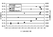
図1に、横軸を第二反応工程前のPcr(=1/((3CO+4CO2+)/H2)とし、縦軸を反応後のCO2濃度及びH2濃度とした設定条件1、設定条件2および設定条件3の結果を示す。図2には、同じく縦軸をCO濃度及びH2濃度とした結果を示す。
図1、2より、いずれの設定条件においても第二反応工程前のPcrの変化に対して、第二反応工程後のCO2濃度およびCO濃度がPcr≒1.0近傍で急激に減少し、対数軸に対して変曲点をもつことが明らである。
(simulation result)
In FIG. 1, the horizontal axis is Pcr before the second reaction step (= 1 / ((3CO + 4CO2 +) / H2), and the vertical axis is the CO2 concentration and H2 concentration after the reaction. The result of
1 and 2, the CO2 concentration and the CO concentration after the second reaction step rapidly decrease in the vicinity of Pcr≈1.0 with respect to the change in Pcr before the second reaction step under any set condition, and the logarithm It is clear that it has an inflection point with respect to the axis.
(変曲点近傍におけるガス組成等の代表例)
表5に変曲点近傍におけるガス組成代表例を示す。
Table 5 shows typical examples of gas composition near the inflection point.
(原料供給比と各成分濃度の関係)
設定条件2について、図3に第二反応工程後のCO2濃度とH2濃度の関係を、図4にCO濃度とH2濃度の関係を、それぞれ示した。これらの図から、化学量論比H2/CO2=4を基軸として、大幅なCO2及びCOの減少と残存H2の増加が認められることが分かる。
(Relationship between raw material supply ratio and component concentration)
Regarding the
(リサイクルなしの場合における組成比パラメータ値の最適値)
設定条件3(リサイクル比:0)について、図5に第二反応工程後の供給ラインにおけるCO2濃度とH2濃度の関係を、図6に同じくCO濃度とH2濃度の関係を、それぞれ示した。各濃度はそれぞれH2O除去後の値である。反応器温度条件は300℃である(一部、282℃条件の値も付記してある)。
図5、図6より、第二反応工程前の組成比パラメータPcr値=1.00近傍でメタン純度が最大値(約94%)を示し、1.00以上では純度が低下する。その理由は、図6から明らかなように、Pcrが1.00以上において残存H2濃度が極めて大きくなることにある。一方、残存CO2濃度は、Pcrの増加に伴い著しく低下し、特に1.00以上では顕著である。
以上の結果より、供給ラインにおけるH2及びCO2濃度を下げ、メタン純度を高くするには、Pcr=1.00−1.02が最適であると判断される。
なお、図5、図6には、第二反応工程の温度条件を282℃に下げた結果を示した(白抜き記号で表示)。本検討条件は、表4においてCase37に該当し、温度条件以外はCase35と同一である。これより、供給ラインにおけるメタン純度(93.0 vol%→93.6vol%)、不純物としてのCO2(2,229 molppm→952 molppm)やH2(58,262 molppm→53,342 molppm)の絶対濃度が改良される方向を示している。
(Optimum value of composition ratio parameter value without recycling)
For setting condition 3 (recycling ratio: 0), FIG. 5 shows the relationship between the CO2 concentration and the H2 concentration in the supply line after the second reaction step, and FIG. 6 shows the relationship between the CO concentration and the H2 concentration. Each concentration is a value after removal of H2O. The reactor temperature condition is 300 ° C. (some of the values for the 282 ° C. condition are also included).
5 and 6, the methane purity shows the maximum value (about 94%) in the vicinity of the composition ratio parameter Pcr value = 1.00 before the second reaction step, and the purity decreases at 1.00 or more. The reason is that, as is apparent from FIG. 6, the residual H2 concentration becomes extremely large when Pcr is 1.00 or more. On the other hand, the residual CO2 concentration significantly decreases with an increase in Pcr, and is particularly remarkable at 1.00 or higher.
From the above results, it is determined that Pcr = 1.00-1.02 is optimal for reducing the H2 and CO2 concentrations in the supply line and increasing the methane purity.
5 and 6 show the results of lowering the temperature condition of the second reaction step to 282 ° C. (indicated by white symbols). This examination condition corresponds to Case 37 in Table 4, and is the same as Case 35 except for the temperature condition. From this, the methane purity (93.0 vol% → 93.6 vol%) in the supply line, the absolute concentration of CO2 (2,229 molppm → 952 molppm) and H2 (58,262 molppm → 53,342 molppm) as impurities are shown to be improved. .
本発明により合成されるメタンは、都市ガス供給用途のみならず、発電用燃料、NGV(天然ガス自動車)等、高純度のメタン供給が要求される用途、分野に広く適用可能である。 The methane synthesized by the present invention can be widely applied not only to city gas supply applications but also to applications and fields where high-purity methane supply is required, such as power generation fuel and NGV (natural gas vehicle).
1・・・・メタン合成装置
2a−2d・・・・コンプレッサ
3、5・・・・反応器
4・・・・CO2再生ユニット
6a、6b・・・・フラッシュ蒸留塔
7・・・・PSA
8・・・・原料ライン
9・・・・H2回収ライン
10・・・・CO2回収ライン
11、21・・・供給ガスライン
12a、12b、22a、22b・・・H2O除去ライン
DESCRIPTION OF
8 ... Raw material line 9 ...
Claims (6)
二酸化炭素と水素を反応させて、一酸化炭素を得る第一反応工程と、
第一反応工程により生成した一酸化炭素と水素を反応させて、メタンを得る第二反応工程と、
を含むことを特徴とする二酸化炭素と水素からメタンを合成する方法。 A method of synthesizing methane from carbon dioxide and hydrogen,
A first reaction step of reacting carbon dioxide and hydrogen to obtain carbon monoxide;
A second reaction step of reacting carbon monoxide produced in the first reaction step with hydrogen to obtain methane;
A method for synthesizing methane from carbon dioxide and hydrogen, characterized by comprising:
組成比パラメータ(Pcr)=1/((3CO+4CO2)/H2) の値が、1.0乃至1.1となるように、原料である水素及び一酸化炭素の供給比と、二酸化炭素水素及び水素の分離・リサイクル比と、を制御する、
ことを特徴とする請求項1に記載の二酸化炭素と水素からメタンを合成する方法。 In the second reaction step, the composition ratio (molar conversion) of hydrogen and carbon monoxide as raw materials and carbon dioxide remaining in the first reaction step,
Composition ratio parameter (Pcr) = 1 / ((3CO + 4CO2) / H2) The feed ratio of hydrogen and carbon monoxide as raw materials, and carbon dioxide hydrogen and hydrogen so that the value is 1.0 to 1.1 Controlling the separation / recycling ratio of
The method for synthesizing methane from carbon dioxide and hydrogen according to claim 1.
前記第二反応工程後に、水素を分離することなく水のみを分離する工程と、
を、さらに含むことを特徴とする請求項1乃至3のいずれかに記載の二酸化炭素と水素からメタンを合成する方法。 A step of separating only water without separating carbon dioxide after the first reaction step;
A step of separating only water without separating hydrogen after the second reaction step;
The method for synthesizing methane from carbon dioxide and hydrogen according to any one of claims 1 to 3, further comprising:
前記第二反応工程における反応温度を250−450℃に設定する、
ことを特徴とする請求項1乃至4のいずれかに記載の二酸化炭素と水素からメタンを合成する方法。 Setting the reaction temperature in the first reaction step to 460-550 ° C .;
Setting the reaction temperature in the second reaction step to 250-450 ° C;
The method for synthesizing methane from carbon dioxide and hydrogen according to any one of claims 1 to 4.
Priority Applications (1)
| Application Number | Priority Date | Filing Date | Title |
|---|---|---|---|
| JP2011000451A JP5562873B2 (en) | 2011-01-05 | 2011-01-05 | Method for synthesizing methane from carbon dioxide and hydrogen |
Applications Claiming Priority (1)
| Application Number | Priority Date | Filing Date | Title |
|---|---|---|---|
| JP2011000451A JP5562873B2 (en) | 2011-01-05 | 2011-01-05 | Method for synthesizing methane from carbon dioxide and hydrogen |
Publications (2)
| Publication Number | Publication Date |
|---|---|
| JP2012140382A true JP2012140382A (en) | 2012-07-26 |
| JP5562873B2 JP5562873B2 (en) | 2014-07-30 |
Family
ID=46677063
Family Applications (1)
| Application Number | Title | Priority Date | Filing Date |
|---|---|---|---|
| JP2011000451A Active JP5562873B2 (en) | 2011-01-05 | 2011-01-05 | Method for synthesizing methane from carbon dioxide and hydrogen |
Country Status (1)
| Country | Link |
|---|---|
| JP (1) | JP5562873B2 (en) |
Cited By (6)
| Publication number | Priority date | Publication date | Assignee | Title |
|---|---|---|---|---|
| JP2018165256A (en) * | 2017-03-28 | 2018-10-25 | 東京瓦斯株式会社 | Methane production method and methane production system |
| WO2019082538A1 (en) | 2017-10-26 | 2019-05-02 | 日立造船株式会社 | Gas generation device and gas generation method |
| WO2020189127A1 (en) | 2019-03-19 | 2020-09-24 | 日立造船株式会社 | Methane production system |
| WO2021251471A1 (en) | 2020-06-10 | 2021-12-16 | 三菱パワー株式会社 | Co2 methanation reaction apparatus provided with selective oxidation catalyst for co, and metod for removing co from gas |
| WO2022138910A1 (en) * | 2020-12-25 | 2022-06-30 | Eneos株式会社 | Hydrocarbon production method |
| WO2023100835A1 (en) * | 2021-11-30 | 2023-06-08 | 積水化学工業株式会社 | Apparatus for producing olefin compound |
Families Citing this family (1)
| Publication number | Priority date | Publication date | Assignee | Title |
|---|---|---|---|---|
| JP7406205B2 (en) | 2020-03-24 | 2023-12-27 | 横河電機株式会社 | Methane generator |
Citations (5)
| Publication number | Priority date | Publication date | Assignee | Title |
|---|---|---|---|---|
| JPH06263665A (en) * | 1993-03-12 | 1994-09-20 | Agency Of Ind Science & Technol | Catalytic hydrogenation of carbon dioxide gas |
| JPH09110731A (en) * | 1995-10-24 | 1997-04-28 | Chikyu Kankyo Sangyo Gijutsu Kenkyu Kiko | Production of methane |
| JPH10263400A (en) * | 1997-03-24 | 1998-10-06 | Ishii Iron Works Co Ltd | Amorphous alloy catalyst for reformed gas of hydrocarbon and use of the catalyst |
| JP2007503503A (en) * | 2003-08-22 | 2007-02-22 | サソール テクノロジー(プロプライエタリー)リミテッド | Hydrocarbon synthesis method |
| JP2009034650A (en) * | 2007-08-03 | 2009-02-19 | Daiki Ataka Engineering Co Ltd | Methanation catalyst of carbon oxide, its manufacturing method and methanation method |
-
2011
- 2011-01-05 JP JP2011000451A patent/JP5562873B2/en active Active
Patent Citations (5)
| Publication number | Priority date | Publication date | Assignee | Title |
|---|---|---|---|---|
| JPH06263665A (en) * | 1993-03-12 | 1994-09-20 | Agency Of Ind Science & Technol | Catalytic hydrogenation of carbon dioxide gas |
| JPH09110731A (en) * | 1995-10-24 | 1997-04-28 | Chikyu Kankyo Sangyo Gijutsu Kenkyu Kiko | Production of methane |
| JPH10263400A (en) * | 1997-03-24 | 1998-10-06 | Ishii Iron Works Co Ltd | Amorphous alloy catalyst for reformed gas of hydrocarbon and use of the catalyst |
| JP2007503503A (en) * | 2003-08-22 | 2007-02-22 | サソール テクノロジー(プロプライエタリー)リミテッド | Hydrocarbon synthesis method |
| JP2009034650A (en) * | 2007-08-03 | 2009-02-19 | Daiki Ataka Engineering Co Ltd | Methanation catalyst of carbon oxide, its manufacturing method and methanation method |
Cited By (8)
| Publication number | Priority date | Publication date | Assignee | Title |
|---|---|---|---|---|
| JP2018165256A (en) * | 2017-03-28 | 2018-10-25 | 東京瓦斯株式会社 | Methane production method and methane production system |
| WO2019082538A1 (en) | 2017-10-26 | 2019-05-02 | 日立造船株式会社 | Gas generation device and gas generation method |
| US11065590B2 (en) | 2017-10-26 | 2021-07-20 | Hitachi Zosen Corporation | Gas generation device and gas generation method |
| WO2020189127A1 (en) | 2019-03-19 | 2020-09-24 | 日立造船株式会社 | Methane production system |
| US11807590B2 (en) | 2019-03-19 | 2023-11-07 | Hitachi Zosen Corporation | Methane production system |
| WO2021251471A1 (en) | 2020-06-10 | 2021-12-16 | 三菱パワー株式会社 | Co2 methanation reaction apparatus provided with selective oxidation catalyst for co, and metod for removing co from gas |
| WO2022138910A1 (en) * | 2020-12-25 | 2022-06-30 | Eneos株式会社 | Hydrocarbon production method |
| WO2023100835A1 (en) * | 2021-11-30 | 2023-06-08 | 積水化学工業株式会社 | Apparatus for producing olefin compound |
Also Published As
| Publication number | Publication date |
|---|---|
| JP5562873B2 (en) | 2014-07-30 |
Similar Documents
| Publication | Publication Date | Title |
|---|---|---|
| JP5562873B2 (en) | Method for synthesizing methane from carbon dioxide and hydrogen | |
| JP5355062B2 (en) | Co-production method of methanol and ammonia | |
| CA2800285C (en) | Process for producing ammonia synthesis gas | |
| CN101830775B (en) | Co-production of methanol and ammonia | |
| RU2524720C2 (en) | Complex installation for gas processing | |
| KR101717121B1 (en) | Co-production of methanol and ammonia | |
| KR101429973B1 (en) | Apparatus and method for producing synthetic natural gas using synthesis gas of low H2/CO ratio | |
| EA035718B1 (en) | Integrated process for the production of formaldehyde-stabilised urea | |
| CN110177772B (en) | Combined production of methanol, ammonia and urea | |
| WO2019020376A1 (en) | Method for the preparation of ammonia synthesis gas | |
| CN106431834A (en) | Combined reforming process for methanol production | |
| EP2906523A1 (en) | Efficient, self sufficient production of methanol from a methane source via oxidative bi-reforming | |
| EA012491B1 (en) | An integrated process for the co-production of methanol and dimethyl ether from syngas containing nitrogen | |
| JP2008505047A (en) | Preparation of synthesis gas for acetic acid synthesis by partial oxidation of methanol feedstock | |
| JP2022022978A (en) | Coproduction method of methanol and methane, and coproduction facility of methanol and methane | |
| JPH03200734A (en) | Synthesis of methanol | |
| JP2011241182A (en) | Method for synthesizing methane from carbon dioxide and hydrogen | |
| JP4487175B2 (en) | Method for producing methanol from biomass | |
| CN105829240B (en) | The method for producing ammonia synthesis gas | |
| JP2006513128A (en) | Improved shift conversion arrangement and method. | |
| JP2022012436A (en) | Method for manufacturing methanol and methane in combination, and apparatus for manufacturing methanol and methane in combination | |
| KR101628661B1 (en) | Apparatus and method for producing synthetic natural gas | |
| CN111848352A (en) | Reduction of CO by coke2Process for preparing methanol | |
| JP2007246486A (en) | Methanol manufacturing plant and methanol manufacturing method | |
| US20230219815A1 (en) | System network and method for operating a system network of this type for producing higher alcohols |
Legal Events
| Date | Code | Title | Description |
|---|---|---|---|
| A621 | Written request for application examination |
Free format text: JAPANESE INTERMEDIATE CODE: A621 Effective date: 20130215 |
|
| A977 | Report on retrieval |
Free format text: JAPANESE INTERMEDIATE CODE: A971007 Effective date: 20140212 |
|
| A131 | Notification of reasons for refusal |
Free format text: JAPANESE INTERMEDIATE CODE: A131 Effective date: 20140325 |
|
| A521 | Request for written amendment filed |
Free format text: JAPANESE INTERMEDIATE CODE: A523 Effective date: 20140516 |
|
| TRDD | Decision of grant or rejection written | ||
| A01 | Written decision to grant a patent or to grant a registration (utility model) |
Free format text: JAPANESE INTERMEDIATE CODE: A01 Effective date: 20140610 |
|
| A61 | First payment of annual fees (during grant procedure) |
Free format text: JAPANESE INTERMEDIATE CODE: A61 Effective date: 20140611 |
|
| R150 | Certificate of patent or registration of utility model |
Ref document number: 5562873 Country of ref document: JP Free format text: JAPANESE INTERMEDIATE CODE: R150 |
|
| R250 | Receipt of annual fees |
Free format text: JAPANESE INTERMEDIATE CODE: R250 |
|
| R250 | Receipt of annual fees |
Free format text: JAPANESE INTERMEDIATE CODE: R250 |
|
| R250 | Receipt of annual fees |
Free format text: JAPANESE INTERMEDIATE CODE: R250 |
|
| R250 | Receipt of annual fees |
Free format text: JAPANESE INTERMEDIATE CODE: R250 |
|
| R250 | Receipt of annual fees |
Free format text: JAPANESE INTERMEDIATE CODE: R250 |
|
| R250 | Receipt of annual fees |
Free format text: JAPANESE INTERMEDIATE CODE: R250 |
|
| R250 | Receipt of annual fees |
Free format text: JAPANESE INTERMEDIATE CODE: R250 |