JP2012139934A - Apparatus for turning flexible cylindrical body inside out - Google Patents
Apparatus for turning flexible cylindrical body inside out Download PDFInfo
- Publication number
- JP2012139934A JP2012139934A JP2010294627A JP2010294627A JP2012139934A JP 2012139934 A JP2012139934 A JP 2012139934A JP 2010294627 A JP2010294627 A JP 2010294627A JP 2010294627 A JP2010294627 A JP 2010294627A JP 2012139934 A JP2012139934 A JP 2012139934A
- Authority
- JP
- Japan
- Prior art keywords
- cylindrical body
- flexible
- flexible cylindrical
- pressure
- pressure vessel
- Prior art date
- Legal status (The legal status is an assumption and is not a legal conclusion. Google has not performed a legal analysis and makes no representation as to the accuracy of the status listed.)
- Pending
Links
Images


Abstract
Description
本発明は可撓性筒状体の裏返し装置に関するものであって、製造上の都合により内外面を逆に製造されたホースを裏返して使用状態とする場合や、内張り材を裏返して管路に挿通して、管路に内張りする場合において使用する、可撓性筒状体の裏返し装置に関するものである。 The present invention relates to a device for turning over a flexible cylindrical body, and when the hose produced by reversing the inner and outer surfaces is turned into a use state by the convenience of production, or the lining material is turned over and turned into a pipeline. The present invention relates to a device for turning over a flexible cylindrical body, which is used in the case of being inserted and lined in a pipeline.
特公昭40−12655号公報には、製作上の都合により常態における筒状体の内外面を逆にして製作されるような可撓性筒状体を流体圧力により裏返して、常態とするための方法が示されている。 Japanese Examined Patent Publication No. 40-12655 discloses a flexible cylindrical body that is manufactured by reversing the inner and outer surfaces of the cylindrical body in a normal state for the convenience of manufacturing, and is made normal by turning it over with fluid pressure. The method is shown.
また特開平5−96621号公報には、ガス導管、水道管、下水道管などの主として地中に埋設された管路に内張りする方法として、柔軟な筒状の内張り材を流体圧力により、内張り材を内側が外側となるように裏返しながら管路に挿通し、前記流体圧力により管路の内面に圧接して内張りする方法が記載されている。 Japanese Patent Laid-Open No. 5-96621 discloses a method of lining a flexible tubular lining material by a fluid pressure as a method of lining a pipeline buried mainly in the ground, such as a gas conduit, a water pipe, and a sewer pipe. Is inserted into the pipe line while turning inside out so that the inner side is the outside, and the inner surface of the pipe line is pressed against the inner surface of the pipe line by the fluid pressure.
これらの方法においては、可撓性筒状体の一端を環状に固定し、その後部の外側に流体圧力を作用させることにより、前記可撓性筒状体をその環状固定部において内側が外側となるように裏返すのである。 In these methods, one end of the flexible cylindrical body is fixed in an annular shape, and fluid pressure is applied to the outer side of the rear portion thereof, so that the flexible cylindrical body is set to the outer side in the annular fixed portion. Turn it over to be.
そしてそのための装置としては、前記特公昭40−12655号公報に示されているように、圧力容器内にコイル状に巻いた可撓性筒状体を収容し、その先端を口金に環状に固定し、前記圧力容器内に流体圧力を作用させることにより前記環状固定部から可撓性筒状体を繰り出して裏返すものと、前記特開平5−96621号公報に記載されているように、可撓性筒状体を圧力容器の外に置き、その可撓性筒状体を圧力容器の後部から挿入して圧力容器を貫通して圧力容器の先端の口金に環状に固定し、圧力容器内に流体圧力を作用させることにより前記環状固定部から可撓性筒状体を繰り出して裏返すものとが知られている。 As an apparatus for that purpose, as shown in the above Japanese Patent Publication No. 40-12655, a flexible cylindrical body wound in a coil shape is accommodated in a pressure vessel, and its tip is fixed in an annular shape to a base. In addition, as described in Japanese Patent Laid-Open No. 5-96621, a flexible cylindrical body is drawn out from the annular fixing portion by turning fluid pressure into the pressure vessel and turned over. Place the flexible cylindrical body outside the pressure vessel, insert the flexible cylindrical body from the rear of the pressure vessel, penetrate the pressure vessel, and fix it annularly to the tip of the pressure vessel. It is known that a flexible cylindrical body is drawn out from the annular fixing portion and turned over by applying fluid pressure.
前者の装置は比較的小口径で長さも比較的短い可撓性筒状体を裏返す装置としては適しているが、大口径の可撓性筒状体や長尺の可撓性筒状体には適していない。このような可撓性筒状体を裏返そうとすると、それを収容するために大きな圧力容器を必要とし、装置が大掛かりなものとなる。 The former device is suitable as a device that flips a flexible tubular body having a relatively small diameter and a relatively short length, but it is suitable for a flexible tubular body having a large diameter or a long flexible tubular body. Is not suitable. If such a flexible cylindrical body is to be turned over, a large pressure vessel is required to accommodate it, and the apparatus becomes large.
後者の装置によればこのような問題は生じないが、可撓性筒状体が圧力容器を貫通するため、可撓性筒状体が圧力容器に進入する導入口の部分において、可撓性筒状体の周囲をシール部材でシールする必要があるが、そのシール部材が可撓性筒状体の全周に亙って適切に圧接して、シールすることが困難である。 According to the latter apparatus, such a problem does not occur. However, since the flexible cylindrical body penetrates the pressure vessel, the flexible cylindrical body is flexible at the portion of the introduction port that enters the pressure vessel. Although it is necessary to seal the periphery of a cylindrical body with a sealing member, it is difficult for the sealing member to be properly pressed and sealed over the entire circumference of the flexible cylindrical body.
前述のような管路の内張りに使用する内張り材においては、強度を確保するために厚みが必要であり、厚みのあるものを裏返して内張りするためには、小径のものの内側に大径のものを挿通した構造のものとならざるを得ない。 In the lining material used for the lining of the pipeline as described above, the thickness is necessary to ensure the strength, and in order to reverse the thick material and line it up, the small diameter material is inside the small diameter material. It must be of a structure that is inserted through.
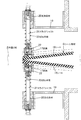
特に下水道管の内張り材においては図1に示すように、管路1の内側に内張り材2を貼り付けるのであるが、その内張り材2は最内層に筒状織布に気密処理を施した気密層3を形成し、当該気密層3の外側に一層乃至数層の不織布層4を形成し、当該不織布層4に反応硬化型樹脂液を含浸して硬化させ、一体の内張り材2を形成している。
In particular, as shown in FIG. 1, the lining material 2 is affixed to the inner side of the pipe line 1 in the lining material of a sewer pipe. The
しかしながら内張り材2は内外面が逆になるように製作され、それを裏返して前述の状態とするのであるから、内張り状態において最内層を形成する気密層3は図2に示すように裏返し前には最外部にあり、その気密層3の中により大径の不織布層4が収容されることとなり、当該圧力容器9は図2に示すように部分的に折り畳まれた状態で収容されることとなる。
However, since the lining material 2 is manufactured so that the inner and outer surfaces are reversed and turned upside down, the
特に気密層3は膨張時に破断しないようにするために、前述のように筒状織布に気密処理を施したものが使用され、伸縮性に乏しい。また不織布層4は伸縮性に劣るために、小径に形成したものを拡張することが困難であり、小径の気密層3内に収容するためには図2に示すように折り畳み部5を形成せざるを得ない。
In particular, in order to prevent the
殊に不織布層4が複数層に亙る場合には、内張り状態において外側に位置する不織布層4ほど、径が大きくなるため、気密層3内において大きな折り畳み部5を形成することとなる。
In particular, when the
そのため図2に示すように、内張り材2は気密層3内に複雑に折り畳まれた複数の不織布層4が挿通された状態となり、気密層3の表面にはその折り畳み部5による凹凸が生じ、その外側にシール部材6を押し当てても、気密層3の凹部において気密層3とシール部材6とが密接せず、空所7が生じる。
Therefore, as shown in FIG. 2, the lining material 2 is in a state in which a plurality of
また内張り材2の両側縁から外側のシール部材6は片持ちとなるため、そのシール部材6はその剛性により内張り材2の側縁に沿うことができず、気密層3の側縁と両シール部材6とで三角形の空所8が形成される。そのためこれらの空所7、8を通じて、圧力容器内の圧力流体が後方に漏出する。
Further, since the sealing member 6 on the outer side from both side edges of the lining material 2 is cantilevered, the sealing member 6 cannot follow the side edges of the lining material 2 due to its rigidity, and the side edges of the
さらにシール部材6の外側から流体圧力が作用し、その流体圧力は圧力容器9の導入口10から後方に向かって作用するため、図3に示すようにシール部材6の先端が内側に捲れ返ることがあり、この捲れ返り部から流体圧力が後方に漏出することがある。 Further, fluid pressure acts from the outside of the seal member 6, and the fluid pressure acts rearward from the inlet 10 of the pressure vessel 9, so that the tip of the seal member 6 turns inside as shown in FIG. 3. There is a case where fluid pressure leaks backward from this turning portion.
本発明はかかる事情に鑑みなされたものであって、シール部材6が可撓性筒状体2の全周に亙って適切に密接し、可撓性筒状体2内の表面に凹凸があっても、シール部材6がその凹凸に沿って可撓性筒状体2に密接する可撓性筒状体の裏返し装置を提供することを目的とするものである。 The present invention has been made in view of such circumstances, and the seal member 6 is appropriately brought into close contact over the entire circumference of the flexible cylindrical body 2, and the surface of the flexible cylindrical body 2 is uneven. Even if it exists, it aims at providing the reversing apparatus of the flexible cylindrical body in which the sealing member 6 closely_contact | adheres to the flexible cylindrical body 2 along the unevenness | corrugation.
而して本発明は、先端部に可撓性筒状体の先端を環状に固定する口金を設け、その口金の後部に圧力容器を形成し、当該圧力容器の後部に前記可撓性筒状体を導入する導入口を形成し、当該導入口に前記圧力容器内に突出する柔軟な気密性の材料よりなる一対のシートよりなるシール部材を取り付け、前記シートの先端部を前記圧力容器内の流体圧力により前記導入口を通過する扁平状態の可撓性筒状体の両面に圧接せしめると共に、当該シートの先端部を少なくとも10以上の区画に区分し、各区画をそれぞれ互いに対向するシートに接近する方向に付勢したことを特徴とするものである。 Thus, in the present invention, a base for annularly fixing the tip of the flexible cylindrical body is provided at the tip, a pressure container is formed at the rear of the base, and the flexible cylinder is formed at the rear of the pressure container. An inlet for introducing a body is formed, and a sealing member made of a pair of sheets made of a flexible and airtight material protruding into the pressure vessel is attached to the inlet, and the leading end of the sheet is attached to the inside of the pressure vessel. The flat surface of the flat flexible cylindrical body passing through the introduction port is brought into pressure contact with the fluid pressure, and the leading edge of the sheet is divided into at least 10 sections, and each section approaches each sheet facing each other. It is characterized in that it is urged in the direction.
本発明の装置においては、前記圧力容器の外殻に固定された支持部材に前記区画に対応する摺動軸を摺動自在に嵌合し、当該摺動軸の先端に対応する前記区画を回動自在に軸支し、前記摺動軸をばね手段により前記シートに接近する方向に付勢することが好ましい。また前記シートにおける前記区画と隣接する区画との間に切り込みを形成することが好ましい。 In the apparatus of the present invention, a sliding shaft corresponding to the section is slidably fitted to a support member fixed to the outer shell of the pressure vessel, and the section corresponding to the tip of the sliding shaft is rotated. It is preferable that the shaft is movably supported and the sliding shaft is biased in a direction approaching the seat by a spring means. Moreover, it is preferable to form a notch between the section and the adjacent section in the sheet.
また本発明の装置においては、前記可撓性筒状体の両側縁が通過する位置における前記両シートの先端面に跨って、柔軟な材料よりなる圧接部材を圧接することが好ましい。この装置においては、前記圧接部材を前記可撓性筒状体の両側縁に圧接せしめることが好ましい。 Moreover, in the apparatus of this invention, it is preferable to press-contact the press-contact member which consists of a soft material across the front end surface of the said both sheet | seat in the position where the both-sides edge of the said flexible cylindrical body passes. In this apparatus, it is preferable that the pressure contact member is pressed against both side edges of the flexible cylindrical body.
さらに本発明の装置においては、前記導入口の後方に消音器を設けることが好ましい。この場合、前記消音器が、可撓性筒状体が通過する箱体内に柔軟なプラスチックの発泡体を張り付けてなることが好ましい。 Furthermore, in the apparatus of this invention, it is preferable to provide a silencer behind the said inlet. In this case, it is preferable that the silencer is formed by attaching a soft plastic foam in a box through which the flexible cylindrical body passes.
本発明によれば、シール部材を構成するシートの先端部を複数の区画に区分し、各区画をそれぞれ対向するシートに接近する方向に付勢しているので、可撓性筒状体2の幅方向にシール部材の締め付け力が一定となり、可撓性筒状体2の表面に凹凸があってもその凹凸に沿ってシール部材6が適切に圧接され、前述のような空所7が形成されることがないと共に、前記シートの先端が図2に示すように内側に捲れ返ることがなく、圧力容器内の圧力流体が漏出することがない。
According to the present invention, the leading end of the sheet constituting the seal member is divided into a plurality of sections, and each section is biased in a direction approaching the facing sheet. Even if the surface of the flexible cylindrical body 2 has irregularities, the sealing member 6 is appropriately pressed along the irregularities to form the
以下本発明の実施の形態を図面に基づいて説明する。図4は本発明の可撓性筒状体の裏返し装置を示すものであって、口金11に可撓性筒状体2の先端を環状に固定し、その後部に設けられた圧力容器9内に水又は圧縮空気などの圧力流体を送入し、当該圧力流体の圧力により前記口金11に環状に固定された可撓性筒状体2を、図面に示すように内側が外側となるように裏返し、その裏返された可撓性筒状体2を口金11から前方に送り出すようになっている。 Embodiments of the present invention will be described below with reference to the drawings. FIG. 4 shows an apparatus for turning over a flexible cylindrical body according to the present invention, in which the tip of the flexible cylindrical body 2 is fixed to the base 11 in an annular shape, and the inside of the pressure vessel 9 provided at the rear part thereof The flexible cylindrical body 2 that is fed into the base 11 with a pressure fluid such as water or compressed air and is fixed to the base 11 by the pressure of the pressure fluid so that the inside is the outside as shown in the drawing. The inside of the flexible tubular body 2 turned upside down is sent out from the base 11 forward.
前記口金11と圧力容器9との間には前部遮蔽装置12が設けられ、前記圧力容器9の後部には後部遮蔽装置13が設けられており、当該後部遮蔽装置13の後部には消音器14が設けられている。
A
而して前記圧力容器9は図5及び図6に示されるように、外殻体15の後部に可撓性筒状体2を導入する導入口10が形成されており、当該導入口10の前部には、一対のシート16、16よりなるシール部材6の基部が取り付けられている。 Thus, as shown in FIGS. 5 and 6, the pressure vessel 9 is formed with an introduction port 10 for introducing the flexible cylindrical body 2 at the rear portion of the outer shell body 15. A base portion of a seal member 6 including a pair of sheets 16 and 16 is attached to the front portion.
シート16、16はそれぞれ、可撓性筒状体2の幅よりも大きい幅を有しており、前記導入口10の前部に可撓性筒状体2の通路を挟んで取り付けられ、導入口10から前方に向かって延びており、一対のシート16、16により可撓性筒状体2の上下から挟みつけるように相対向している。 Each of the sheets 16 and 16 has a width larger than the width of the flexible tubular body 2 and is attached to the front portion of the introduction port 10 with the passage of the flexible tubular body 2 interposed therebetween. It extends toward the front from the mouth 10 and is opposed to the pair of sheets 16 and 16 so as to be sandwiched from above and below the flexible cylindrical body 2.
そしてそのシート16、16の先端部は図9に示すように、多数の区画17に区分されており、その各区画17の間には切り込み18が形成されており、その切り込み18により幅方向に屈曲可能となっている。この区画17の数は、できるだけ多い方が良いが、少なくとも10以上であることが必要である。 As shown in FIG. 9, the leading ends of the sheets 16 and 16 are divided into a large number of compartments 17, and cuts 18 are formed between the compartments 17. It can be bent. The number of the compartments 17 should be as large as possible, but it must be at least 10 or more.
そして図5乃至図8に示すように、そのシート16、16の先端部の上下には、前記外殻体15に連結部材19、19により支持された支持部材20、20が取り付けられており、当該支持部材20、20には前記区画17に相当する位置にスライドシャフト21が上下に摺動自在に貫通せしめられている。
As shown in FIGS. 5 to 8, support members 20 and 20 supported by connecting
そして当該スライドシャフト21の先端には、取り付け金具22を介して前記シート16、16の区画17が回動自在に軸支されており、前記支持部材20、20と取り付け金具22との間に介装されたばね手段23により、相対向するシート16、16が互いに接近する方向に付勢されている。
A section 17 of the seats 16, 16 is pivotally supported at the tip of the slide shaft 21 via a mounting
本発明の装置を使用するには、可撓性筒状体2を装置の後方から導入口10を通してシート16、16の間を通し、圧力容器9を貫通して、その可撓性筒状体2の先端を口金11に環状に固定する。 In order to use the apparatus of the present invention, the flexible cylindrical body 2 is passed from the rear of the apparatus through the inlet 10 and between the sheets 16 and 16 and through the pressure vessel 9, and the flexible cylindrical body. The tip of 2 is fixed to the base 11 in an annular shape.
この状態で圧力流体送入口70から圧力容器9内に圧力流体を送入すると、可撓性筒状体2の前記環状固定部分の後部外側に流体圧力が作用し、その可撓性筒状体2が図4に示すように折り返し部分2aにおいて内側が外側となるように裏返され、それに伴って折り返し部分2aが口金11の前方に押し出される。
In this state, when the pressure fluid is fed into the pressure vessel 9 from the
そして後方の可撓性筒状体2が前方に引き出されて順次前記折り返し部分2aにおいて裏返され、その折り返し部分2aが前方に進行しながら順次可撓性筒状体2を裏返し、可撓性筒状体2の全長に亙って裏返されるのである。
Then, the rear flexible cylindrical body 2 is pulled forward and sequentially turned over at the folded
また前述の管路1に内張りする場合においては、内張り材2内に反応硬化型の接着剤を注入して不織布層4に含浸させておき、それを上記のように流体圧力で裏返しながら管路1に送入することにより、接着剤を含浸した不織布層4が管路1の内面に当接し、接着剤を硬化させることにより、管路1に内張りすることができる。
Further, in the case of lining the pipe 1 described above, a reaction hardening type adhesive is injected into the lining material 2 to impregnate the
本発明の装置においては、支持部材20、20と取り付け金具22との間にばね手段23が介装され、当該ばね手段23によりシート16、16の先端部が前記区画17ごとに互いに圧接せしめられているので、図10に実線で示すようにシート16、16の先端同士が互いに圧接し、シート16、16の間から圧力容器9内の圧力流体が漏出することがない。
In the apparatus of the present invention, the spring means 23 is interposed between the support members 20, 20 and the mounting
またシート16、16の間に可撓性筒状体2を挿入すると、シート16、16は可撓性筒状体2により押し開かれ、図9及び図10に鎖線で示すように、スライドシャフト21はばね手段23を圧縮しながら上下に開き、シート16、16の間に可撓性筒状体2が通過することができる。 Further, when the flexible cylindrical body 2 is inserted between the sheets 16 and 16, the sheets 16 and 16 are pushed open by the flexible cylindrical body 2, and as shown by a chain line in FIG. 9 and FIG. 21 opens up and down while compressing the spring means 23, and the flexible cylindrical body 2 can pass between the sheets 16 and 16.
またシート16、16の先端部は各区画17ごとにばね手段23の弾力により可撓性筒状体2に圧接せしめられており、その圧接力は可撓性筒状体2の全幅において一定となり、内張り材2の表面に凹凸があっても図2において述べたような空所7が形成されることはなく内面に塗布された接着剤が均一に塗布される。
The leading ends of the sheets 16 and 16 are pressed against the flexible cylindrical body 2 by the elastic force of the spring means 23 for each section 17, and the pressing force is constant over the entire width of the flexible cylindrical body 2. Even if the surface of the lining material 2 is uneven, the
また各シート16、16の先端部はスライドシャフト21に取り付けられており、その位置においてばね手段23の弾力に抗して上下には動くことができるが、可撓性筒状体2の前後方向には動くことができず、前記図3に示したように圧力容器9内の流体圧力により内側に捲れ返ることがない。 Further, the front ends of the sheets 16 and 16 are attached to the slide shaft 21 and can move up and down against the elasticity of the spring means 23 at that position. 3 and cannot be turned inward by the fluid pressure in the pressure vessel 9 as shown in FIG.
なお、上記の本発明においては、スライドシャフト21がシート16、16を押圧する方向が上下方向のみであるため、可撓性筒状体2の側縁とシート16、16の区画17との位置関係によっては、可撓性筒状体2の側縁とシート16、16の対向面との間に空所8が形成されるのを避けることができない。
In the present invention, since the slide shaft 21 presses the sheets 16 and 16 only in the vertical direction, the position of the side edge of the flexible cylindrical body 2 and the section 17 of the sheets 16 and 16 is determined. Depending on the relationship, it is unavoidable that the
この場合には、可撓性筒状体2の両側縁におけるシート16、16の先端面に跨って、柔軟な素材よりなる圧接部材24を圧接し、前記空所8から圧力容器9内の圧力流体が漏出するのを防止するのが好ましい。
In this case, a pressure contact member 24 made of a flexible material is pressed across the front end surfaces of the sheets 16 and 16 on both side edges of the flexible cylindrical body 2, and the pressure in the pressure vessel 9 from the
その圧接部材24を圧接する圧接装置25は図6及び図8に示されている。この圧接装置25は、圧力容器9の両側壁間に上下一対のバー26が固定されており、当該バー26に左右一対の摺動部材27が摺動自在に取り付けられ、当該摺動部材27に取り付けられた雌ネジ部材28に雄ネジ部材29が螺合され、当該雄ネジ部材29を圧力容器9の外からハンドル30により回転操作し、圧接部材24の位置を調節することができるようになっている。
A
そして摺動部材27間に取り付けられた支持板31に摺動杆32が摺動自在に支持され、当該摺動杆32の先端に前記圧接部材24が取り付けられ、ばね手段33により常時前記シート16、16の先端面に圧接せしめられる。
A sliding
また前記ハンドル30を回転操作することにより、圧接部材24の側面を可撓性筒状体2の側縁に圧接して前記空所8を完全に塞ぐことができ、前記空所8を通じて後方に圧力流体が漏出するのを阻止することができる。
Further, by rotating the
しかしながら、後方への圧力流体の漏出を100%完全に阻止することは困難であり、ある程度の漏出はやむを得ないことであり、そのときには導入口10から圧力流体が放出され、放出音が生じる。 However, it is difficult to completely prevent leakage of the pressure fluid to the rear, and some leakage is unavoidable. At that time, the pressure fluid is discharged from the inlet 10 and a discharge sound is generated.
従ってその放出音を軽減するために、導入口10の後方に消音器14を設けるのが好ましい。この消音器14は、可撓性筒状体2が通過する箱体34内に柔軟なプラスチックの発泡体35を張り付けてなるものとするのが好ましい。 Therefore, in order to reduce the emitted sound, it is preferable to provide a silencer 14 behind the introduction port 10. The silencer 14 is preferably formed by attaching a soft plastic foam 35 in a box 34 through which the flexible cylindrical body 2 passes.
前記後部遮蔽装置13は図11に示すように、箱体36の前後の壁面に可撓性筒状体2が通過する開口37、38を有し、当該開口37、38を通過する可撓性筒状体2を挟んで、上下に相対向して遮蔽板39が設けられており、その遮蔽板39の相対向する端部には柔軟な素材よりなる挟圧部40が設けられている。なお41は、後部遮蔽装置13の後部壁面と前記遮蔽板39の背面との間をシールするパッキンである。
As shown in FIG. 11, the
そして両遮蔽板39には雌ネジ部材42が取り付けられており、当該雌ネジ部材42に雄ネジ部材43が螺合されている。前記箱体36の一側部に設けられたモーター44及び減速機45によりかさ歯歯車46、47を介して駆動ロッド48を駆動し、当該駆動ロッド48の両端に設けられたかさ歯歯車49、50により上下に設けられた駆動バー51を駆動し、さらに当該駆動バー51に設けられたかさ歯歯車52が、前記雄ネジ部材43の端末に設けられたかさ歯歯車53に噛合し、雌ネジ部材42を介して遮蔽板39を上下に開閉し、可撓性筒状体2を挟圧して遮蔽するようになっている。
A
可撓性筒状体2の後端にはその後端が通過したのち可撓性筒状体2の裏返りをコントロールするためのベルトが縫着されているため、可撓性筒状体2の断面形状が乱れており、シート16、16の先端部を通過しにくく、その周囲から圧力容器9内の圧力流体が大量に漏出し、圧力容器9内や裏返った可撓性筒状体2内に十分な圧力を作用させることができず、裏返りを進行できない可能性がある。 Since the rear end of the flexible tubular body 2 passes through the rear end thereof, and a belt for controlling the turning over of the flexible tubular body 2 is sewn, the cross section of the flexible tubular body 2 The shape is disordered, it is difficult for the sheets 16 and 16 to pass through the front end portions, and a large amount of the pressure fluid in the pressure vessel 9 leaks from the surroundings, and the pressure vessel 9 or the inside of the flexible tubular body 2 turned inside out. There is a possibility that sufficient pressure cannot be applied, and that turning over cannot proceed.
そのようなときには、前記遮蔽板39を閉じて挟圧部40でベルトを挟みつけ、圧力容器9や裏返った可撓性筒状体2内の流体圧力を十分に確保することにより、可撓性筒状体2の裏返りを進行させることができる。
In such a case, the shielding
また前記前部遮蔽装置12は図12に示すように、箱体54の前後の壁面に可撓性筒状体2が通過する開口55、56を有し、当該開口55、56を通過する可撓性筒状体2の上部に遮蔽板57が設けられており、その遮蔽板57の下端部には柔軟な素材よりなる挟圧部58が設けられており、当該挟圧部58に対向する下部には受け部59が設けられている。なお60は、前部箱体54の後部壁面と前記遮蔽板57の背面との間をシールするパッキンである。
Further, as shown in FIG. 12, the
そして前記遮蔽板57には雌ネジ部材61が取り付けられており、当該雌ネジ部材61に雄ネジ部材62が螺合されている。前記箱体54の上部に設けられたモーター63及び減速機64によりかさ歯歯車65、66を介して駆動バー67を駆動し、当該駆動バー67に設けられたかさ歯歯車68が、前記雄ネジ部材62の上端に設けられたかさ歯歯車69に噛合し、雌ネジ部材61を介して遮蔽板57を上下に開閉し、挟圧部58と受け部59との間に可撓性筒状体2を挟圧して遮蔽するようになっている。
A
なおこの前部遮蔽装置12は可撓性筒状体2の上部に設けられた遮蔽板57のみによって遮蔽するようになっているが、前記後部遮蔽装置13と同様に上下に設けられた遮蔽板によって上下から可撓性筒状体2を挟みつけるようにすることもできる。
The
本発明の装置を管路の内張りに使用する場合には、可撓性筒状体2が裏返って管路に挿通されたのち、可撓性筒状体2の内面に塗布されていた接着剤を硬化させて管路に接着する必要がある。 When the apparatus of the present invention is used for the lining of the pipe, the adhesive applied to the inner surface of the flexible cylindrical body 2 after the flexible cylindrical body 2 is turned over and inserted into the pipe Must be cured and bonded to the conduit.
この場合には、前部遮蔽装置12で圧力容器9と口金11との間を遮蔽することにより、口金11及びそれに接続された裏返された可撓性筒状体2内の流体圧力を保持したままで、圧力容器9及びそれよりも後方の装置を取り外すことができる。
In this case, the pressure between the pressure vessel 9 and the base 11 is shielded by the
2 可撓性筒状体(内張り材)
6 シール部材
9 圧力容器
10 導入口
11 口金
14 消音器
15 外殻体
16 シート
17 区画
18 切り込み
20 支持部材
21 スライドシャフト
23 ばね手段
24 圧接部材
34 箱体
35 発泡体
2 Flexible tubular body (lining material)
6 Seal member 9 Pressure vessel 10 Inlet 11 Base 14 Muffler 15 Outer shell 16 Sheet 17 Partition 18 Notch 20 Support member 21 Slide shaft 23 Spring means 24 Pressure contact member 34 Box 35 Foam
Claims (7)
Priority Applications (1)
| Application Number | Priority Date | Filing Date | Title |
|---|---|---|---|
| JP2010294627A JP2012139934A (en) | 2010-12-31 | 2010-12-31 | Apparatus for turning flexible cylindrical body inside out |
Applications Claiming Priority (1)
| Application Number | Priority Date | Filing Date | Title |
|---|---|---|---|
| JP2010294627A JP2012139934A (en) | 2010-12-31 | 2010-12-31 | Apparatus for turning flexible cylindrical body inside out |
Publications (1)
| Publication Number | Publication Date |
|---|---|
| JP2012139934A true JP2012139934A (en) | 2012-07-26 |
Family
ID=46676713
Family Applications (1)
| Application Number | Title | Priority Date | Filing Date |
|---|---|---|---|
| JP2010294627A Pending JP2012139934A (en) | 2010-12-31 | 2010-12-31 | Apparatus for turning flexible cylindrical body inside out |
Country Status (1)
| Country | Link |
|---|---|
| JP (1) | JP2012139934A (en) |
Citations (5)
| Publication number | Priority date | Publication date | Assignee | Title |
|---|---|---|---|---|
| JPH03106026U (en) * | 1990-02-19 | 1991-11-01 | ||
| JPH07195521A (en) * | 1993-12-31 | 1995-08-01 | Takiron Co Ltd | Lining of inner surface of pipe and hot air discharge machine used therein |
| JP2002273795A (en) * | 2000-12-05 | 2002-09-25 | Tokai Rubber Ind Ltd | Method for manufacturing soundproof cover and soundproof cover |
| WO2006046478A1 (en) * | 2004-10-28 | 2006-05-04 | Shonan Gosei-Jushi Seisakusho K.K. | Method and device for reversing pipe lining material and conduit restoring method using reversing device |
| JP2006306284A (en) * | 2005-04-28 | 2006-11-09 | Yokohama Rubber Co Ltd:The | Pneumatic tire and its manufacturing method |
-
2010
- 2010-12-31 JP JP2010294627A patent/JP2012139934A/en active Pending
Patent Citations (5)
| Publication number | Priority date | Publication date | Assignee | Title |
|---|---|---|---|---|
| JPH03106026U (en) * | 1990-02-19 | 1991-11-01 | ||
| JPH07195521A (en) * | 1993-12-31 | 1995-08-01 | Takiron Co Ltd | Lining of inner surface of pipe and hot air discharge machine used therein |
| JP2002273795A (en) * | 2000-12-05 | 2002-09-25 | Tokai Rubber Ind Ltd | Method for manufacturing soundproof cover and soundproof cover |
| WO2006046478A1 (en) * | 2004-10-28 | 2006-05-04 | Shonan Gosei-Jushi Seisakusho K.K. | Method and device for reversing pipe lining material and conduit restoring method using reversing device |
| JP2006306284A (en) * | 2005-04-28 | 2006-11-09 | Yokohama Rubber Co Ltd:The | Pneumatic tire and its manufacturing method |
Similar Documents
| Publication | Publication Date | Title |
|---|---|---|
| AU677229B2 (en) | Improvements relating to the lining of pipelines and passageways | |
| US4325772A (en) | Method of internally lining an installed pipe | |
| JP2564092B2 (en) | Branch pipe lining method | |
| JP2667796B2 (en) | Pipe lining method | |
| US20100012214A1 (en) | Pipe lining material and method for manufacturing same | |
| JPH0745182B2 (en) | Method for manufacturing pipe lining material | |
| KR0178146B1 (en) | Method for everting a tubular liner bag | |
| JP2012139934A (en) | Apparatus for turning flexible cylindrical body inside out | |
| JP5397260B2 (en) | Cloth bonding apparatus and cartridge | |
| JP5748478B2 (en) | Pipeline lining device | |
| JP2000000890A (en) | Apparatus for lining branch pipe | |
| JP3784901B2 (en) | Pipe line rehabilitation equipment such as drain pipes | |
| JPH01242231A (en) | Liner reversal apparatus in construction method for repairing pipeline | |
| TW467825B (en) | Tube lining and the manufacturing method therefor | |
| JPH0926083A (en) | Pipe branch part repairing device | |
| JP3179804B2 (en) | Flexible tubular body flipping device | |
| JP2955355B2 (en) | Liner sealing device in pipeline liner | |
| CN209871285U (en) | Special liquid bag for disaster relief | |
| KR20140000806A (en) | Apparatus for reversing tube of pipe line repair and method for repairing pipe line using the same | |
| JP2678149B2 (en) | Branch pipe lining material and branch pipe lining method | |
| JP2678151B2 (en) | Pipe lining material and method of manufacturing the same | |
| JP2004148512A (en) | Pipe lining method | |
| JP2826816B2 (en) | Branch pipe repair equipment | |
| RU2366853C1 (en) | Seal joint | |
| JPH1120020A (en) | Branch pipe lining material and method for lining branch pipe using it |
Legal Events
| Date | Code | Title | Description |
|---|---|---|---|
| A621 | Written request for application examination |
Free format text: JAPANESE INTERMEDIATE CODE: A621 Effective date: 20131114 |
|
| A977 | Report on retrieval |
Free format text: JAPANESE INTERMEDIATE CODE: A971007 Effective date: 20141023 |
|
| A131 | Notification of reasons for refusal |
Free format text: JAPANESE INTERMEDIATE CODE: A131 Effective date: 20141104 |
|
| A02 | Decision of refusal |
Free format text: JAPANESE INTERMEDIATE CODE: A02 Effective date: 20150414 |