JP2012139610A - Stirring rotor and stirring device - Google Patents

Stirring rotor and stirring device Download PDF

Info

Publication number
JP2012139610A
JP2012139610A JP2010291987A JP2010291987A JP2012139610A JP 2012139610 A JP2012139610 A JP 2012139610A JP 2010291987 A JP2010291987 A JP 2010291987A JP 2010291987 A JP2010291987 A JP 2010291987A JP 2012139610 A JP2012139610 A JP 2012139610A
Authority
JP
Japan
Prior art keywords
stirring
discharge port
suction port
long hole
rotation axis
Prior art date
Legal status (The legal status is an assumption and is not a legal conclusion. Google has not performed a legal analysis and makes no representation as to the accuracy of the status listed.)
Granted
Application number
JP2010291987A
Other languages
Japanese (ja)
Other versions
JP5702598B2 (en
Inventor
Kazuhisa Murata
和久 村田
Current Assignee (The listed assignees may be inaccurate. Google has not performed a legal analysis and makes no representation or warranty as to the accuracy of the list.)
EDDY PLUS CO Ltd
Original Assignee
EDDY PLUS CO Ltd
Priority date (The priority date is an assumption and is not a legal conclusion. Google has not performed a legal analysis and makes no representation as to the accuracy of the date listed.)
Filing date
Publication date
Application filed by EDDY PLUS CO Ltd filed Critical EDDY PLUS CO Ltd
Priority to JP2010291987A priority Critical patent/JP5702598B2/en
Publication of JP2012139610A publication Critical patent/JP2012139610A/en
Application granted granted Critical
Publication of JP5702598B2 publication Critical patent/JP5702598B2/en
Active legal-status Critical Current
Anticipated expiration legal-status Critical

Links

Images

Abstract

PROBLEM TO BE SOLVED: To provide a stirring rotor and a stirring device, performable of a stirring operation in a safe and efficient manner, irrespective of intended purposes.SOLUTION: The stirring rotor 1 comprises a rotor body 10 adapted to be rotated about a rotation axis (center axis C), an inlet port 12 provided in the outer surface of the rotor body 10, an outlet port 14 provided in the outer surface of the rotor body 10, and a flow passage 16 making the inlet port 12 communicate with the outlet port 14. The inlet port 12 is provided at a position closer to the rotation axis than to the outlet port 14. The outlet port 14 is provided at a position more outward in a centrifugal direction from the rotation axis than the inlet port 12. At least one of the inlet port 12 or the outlet port 14 is made a long hole.

Description

本発明は、液体その他の各種流体を攪拌し、混合、分散等を行うための攪拌用回転体および攪拌装置に関する。   The present invention relates to a rotating body for stirring and a stirring device for stirring, mixing, dispersing, and the like of liquids and other various fluids.

従来、例えば2種類以上の流体を混合したり、流体中に添加した各種粉末等を均一に分散させたりする場合には、流体中で羽根車を回転させる攪拌機が使用されている。この羽根車には一般的にプロペラ翼やタービン翼が設けられており、回転することで流体を流動させて攪拌を行う。   Conventionally, for example, when two or more kinds of fluids are mixed or various powders added to the fluid are uniformly dispersed, a stirrer that rotates an impeller in the fluid is used. This impeller is generally provided with a propeller blade and a turbine blade, and agitation is performed by flowing a fluid by rotating.

このような攪拌機は、流体を収容するタンクに恒常的に設置されて使用されるものが多いが、この他にも、例えば塗料等を使用直前に現場で攪拌するためのハンディタイプのものがよく使用されている。このハンディタイプの攪拌機は、一般的にハンドドリル型の駆動装置の駆動軸の先端に羽根車を設けて構成されている。そして、使用者は、駆動装置を両手に持ち、先端の羽根車を塗料等の被攪拌物が収容された容器内に挿入して回転させ、攪拌を行う。   Such a stirrer is often used by being permanently installed in a tank containing a fluid, but in addition to this, for example, a handy type for stirring a paint etc. on the spot immediately before use is often used. in use. This handy type agitator is generally configured by providing an impeller at the tip of a drive shaft of a hand drill type drive device. Then, the user holds the drive device in both hands, inserts the impeller at the tip into a container in which an object to be stirred such as a paint is stored, rotates it, and performs stirring.

しかしながら、このハンディタイプの攪拌機では、鋭利な翼端を持つ羽根車を高速で回転させることから非常に危険であり、取扱に注意を要するという問題があった。また、突起の多い羽根車を容器にぶつけてしまった場合や、羽根車が疲労破壊を起こした場合に、羽根車の先端や容器の一部が欠けて、または削れて被攪拌物内に混入しやすいという問題があった。   However, this handy type stirrer is very dangerous because an impeller having a sharp blade tip is rotated at a high speed, and there is a problem that it requires careful handling. Also, if an impeller with many protrusions hits the container, or if the impeller causes fatigue failure, the tip of the impeller or part of the container is missing or scraped and mixed into the object to be stirred. There was a problem that it was easy to do.

また、羽根車は被攪拌物と衝突することによって被攪拌物を流動させるため、羽根車を備える攪拌機では、回転する羽根車を被攪拌物内に投入する際、または被攪拌物内で羽根車の回転を開始する際に、反動によって羽根車が振られやすいという問題があった。このため、使用者が攪拌機の操作になれていない場合には、羽根車を容器にぶつけたり、被攪拌物を容器外に飛散させたりといったような事態が頻発していた。   Also, since the impeller causes the material to be stirred to flow by colliding with the material to be stirred, in a stirrer equipped with an impeller, when the rotating impeller is put into the material to be stirred, or in the material to be stirred, When starting to rotate, there was a problem that the impeller was easily shaken by the reaction. For this reason, when the user is not operating the stirrer, situations such as hitting the impeller against the container or scattering the object to be stirred out of the container frequently occurred.

また、羽根車では、被攪拌物に沈降物が含まれるような場合に、羽根車を容器の底壁に接触させながら攪拌を行わなければ沈降物をうまく分散させることができないため、羽根車と容器の壁面の接触により発生する破片や削りカスが被攪拌物内に混入しやすいという問題があった。   In addition, in the impeller, when the agitated material contains sediment, the sediment cannot be dispersed well unless stirring is performed while the impeller is in contact with the bottom wall of the container. There has been a problem that debris and scraps generated by contact with the wall surface of the container are likely to be mixed into the object to be stirred.

また、羽根車を備える攪拌機では、被攪拌物内に混入された粉末粒子が羽根車との衝突により粉砕される場合があるという問題があった。このため、例えばメタリック塗料のように、混入された粉末粒子を微細化したくないような場合には、十分な攪拌を行うことが困難であった。   Moreover, in the stirrer provided with the impeller, there is a problem that the powder particles mixed in the object to be stirred may be pulverized by collision with the impeller. For this reason, it is difficult to sufficiently stir, for example, when it is not desired to make the mixed powder particles finer, such as a metallic paint.

一方、プロペラ翼やタービン翼を使用するのではなく、外形が六角柱状の筒体から羽根車を構成すると共に、側面に複数の孔を設けた高粘性流体用ミキサー等も提案されている(例えば、特許文献1参照)。   On the other hand, instead of using propeller blades and turbine blades, a mixer for a high-viscosity fluid in which an impeller is configured from a hexagonal cylindrical body and a plurality of holes are provided on a side surface has been proposed (for example, , See Patent Document 1).

特開平5−154368号公報JP-A-5-154368

しかしながら、上記特許文献1に記載の高粘性流体用ミキサーでは、羽根車の外形が六角柱状であり、主として羽根車の外壁を被攪拌物に衝突させることによって被攪拌物を流動させるものであるため、上述した回転開始時の反動の問題、および被攪拌物内の粉末粒子の粉砕の問題を解消するものではなかった。   However, in the high-viscosity fluid mixer described in Patent Document 1, the outer shape of the impeller is a hexagonal column, and the agitated object is caused to flow mainly by colliding the outer wall of the impeller with the agitated object. The above-mentioned problem of recoil at the start of rotation and the problem of pulverization of powder particles in the object to be stirred were not solved.

また、側面の孔から被攪拌物を流出させるようにしているものの、側面の孔に対して羽根車内部の容積が大きいため、羽根車内部の流速が低く、長時間使用した場合に滞留物が羽根車の内側に付着して堆積し、攪拌能力が低下しやすいという問題があった。   In addition, although the agitated material is allowed to flow out from the side holes, the volume inside the impeller is large relative to the side holes, so the flow rate inside the impeller is low, and the stagnant material will remain when used for a long time. There was a problem that the stirring ability was liable to deteriorate due to adhesion and deposition on the inside of the impeller.

本発明は、斯かる実情に鑑みてなされたものであって、用途を問わずに安全且つ効率的な攪拌を行うことが可能な攪拌用回転体および攪拌装置を提供しようとするものである。   This invention is made | formed in view of such a situation, Comprising: It aims at providing the rotary body for stirring and stirring apparatus which can perform safe and efficient stirring irrespective of a use.

(1)本発明は、回転軸を中心に回転する本体と、前記本体の表面に設けられる吸入口と、前記本体の表面に設けられる吐出口と、前記吸入口と前記吐出口を繋ぐ流通路と、を備え、前記吸入口は、前記吐出口よりも前記回転軸に近い位置に配置され、前記吐出口は、前記吸入口よりも前記回転軸から遠心方向外側の位置に配置され、前記吸入口または前記吐出口の少なくとも一方は、長孔であることを特徴とする、攪拌用回転体である。   (1) The present invention provides a main body that rotates about a rotation axis, a suction port provided on the surface of the main body, a discharge port provided on the surface of the main body, and a flow passage that connects the suction port and the discharge port. The suction port is disposed at a position closer to the rotation shaft than the discharge port, and the discharge port is disposed at a position on the outer side in the centrifugal direction from the rotation shaft than the suction port. At least one of the opening and the discharge opening is a stirring rotator, which is a long hole.

(2)本発明はまた、前記吐出口は、自身の断面に垂直な方向から見た場合に、前記回転軸方向を長手方向とする長孔であることを特徴とする、上記(1)に記載の攪拌用回転体である。   (2) In the above (1), the present invention is characterized in that the discharge port is a long hole whose longitudinal direction is the rotation axis direction when viewed from a direction perpendicular to its cross section. The rotating body for stirring described.

(3)本発明はまた、前記吐出口は、自身の断面に垂直な方向から見た場合に、前記回転軸に対して角度を有する方向を長手方向とする長孔であることを特徴とする、上記(1)に記載の攪拌用回転体である。   (3) The present invention is also characterized in that the discharge port is a long hole whose longitudinal direction is a direction having an angle with respect to the rotation axis when viewed from a direction perpendicular to its cross section. The rotating body for stirring described in (1) above.

(4)本発明はまた、前記吐出口は、自身の断面に垂直な方向から見た場合に、前記回転軸に対して直交する方向を長手方向とする長孔であることを特徴とする、上記(3)に記載の攪拌用回転体である。   (4) The present invention is also characterized in that the discharge port is a long hole whose longitudinal direction is a direction orthogonal to the rotation axis when viewed from a direction perpendicular to its cross section. It is a rotating body for stirring as described in said (3).

(5)本発明はまた、前記吸入口は、前記回転軸方向から見た場合に、前記回転軸の遠心方向を長手方向とする長孔であることを特徴とする、上記(1)乃至(4)のいずれかに記載の攪拌用回転体である。   (5) The present invention is also characterized in that the suction port is a long hole whose longitudinal direction is the centrifugal direction of the rotating shaft when viewed from the rotating shaft direction. 4) The rotating body for stirring according to any one of 4).

(6)本発明はまた、前記吸入口は、前記回転軸方向から見た場合に、前記回転軸を中心とする円周の接線方向を長手方向とする長孔であることを特徴とする、上記(1)乃至(4)のいずれかに記載の攪拌用回転体である。   (6) The present invention is also characterized in that the suction port is a long hole whose longitudinal direction is a tangential direction of the circumference around the rotation axis when viewed from the direction of the rotation axis. The stirring rotator according to any one of (1) to (4).

(7)本発明はまた、前記吸入口は、前記回転軸方向から見た場合に、前記回転軸を中心とする円周の接線方向に対して角度を有する方向を長手方向とする長孔であることを特徴とする、上記(1)乃至(4)のいずれかに記載の攪拌用回転体である。   (7) In the present invention, the suction port is a long hole whose longitudinal direction is an angle with respect to a tangential direction of a circumference around the rotation axis when viewed from the rotation axis direction. It is a rotating body for stirring according to any one of (1) to (4) above.

(8)本発明はまた、前記吸入口または前記吐出口の少なくとも一方は、湾曲した長孔であることを特徴とする、上記(1)乃至(7)のいずれかに記載の攪拌用回転体である。   (8) In the present invention, at least one of the suction port or the discharge port is a curved long hole, and the rotating body for stirring according to any one of the above (1) to (7) It is.

(9)本発明はまた、前記吸入口または前記吐出口に対応する開口を備えると共に、前記本体の表面に沿ういずれかの方向にスライド可能に配置され、スライドによって前記吸入口または前記吐出口の開口面積を変更するスライド部材を備えることを特徴とする、上記(1)乃至(8)のいずれかに記載の攪拌用回転体である。   (9) The present invention also includes an opening corresponding to the suction port or the discharge port, and is slidable in any direction along the surface of the main body. The stirring rotator according to any one of (1) to (8) above, further comprising a slide member that changes an opening area.

(10)本発明はまた、上記(1)乃至(9)のいずれかに記載の攪拌用回転体を、前記回転軸方向に複数配置して構成されることを特徴とする、攪拌装置である。   (10) The present invention is also a stirrer characterized in that a plurality of the stirrer rotating bodies according to any one of (1) to (9) are arranged in the direction of the rotation axis. .

本発明によれば、用途を問わずに安全且つ効率的な攪拌を行うことが可能という優れた効果を奏し得る。   According to the present invention, it is possible to achieve an excellent effect that it is possible to perform safe and efficient stirring regardless of use.

(a)本発明の第1の実施形態に係る攪拌用回転体の一例を示した平面図である。(b)同攪拌用回転体の一例を示した正面図(側面図も同一)である。(c)同攪拌用回転体の一例を示した底面図である。(A) It is the top view which showed an example of the rotary body for stirring which concerns on the 1st Embodiment of this invention. (B) It is the front view (side view is the same) which showed an example of the rotary body for stirring. (C) It is the bottom view which showed an example of the rotary body for stirring. (a)攪拌用回転体の作動を示した平面図である。(b)攪拌用回転体の作動を示した正面図である。(c)吐出口を拡大して示した図である。(A) It is the top view which showed the action | operation of the rotary body for stirring. (B) It is the front view which showed the action | operation of the rotary body for stirring. (C) It is the figure which expanded and showed the discharge outlet. (a)および(b)攪拌用回転体の使用例を示した概略図である。It is the schematic which showed the usage example of the rotating body for stirring (a) and (b). (a)〜(c)流通路を吐出口に向けて漸次拡大または縮小するように構成した例を示した図である。(A)-(c) It is the figure which showed the example comprised so that a flow path might be expanded or reduced gradually toward a discharge outlet. (a)〜(c)吐出口を中心軸に直交する方向を長手方向とする長孔に構成した例を示した図である。(A)-(c) It is the figure which showed the example which comprised the discharge port to the long hole which makes the direction orthogonal to a central axis the longitudinal direction. (a)〜(c)吐出口を中心軸に直交する方向を長手方向とする長孔に構成した例を示した図である。(A)-(c) It is the figure which showed the example which comprised the discharge port to the long hole which makes the direction orthogonal to a central axis the longitudinal direction. (a)〜(c)吐出口のその他の形態の例を示した正面図(側面図)である。It is the front view (side view) which showed the example of the other form of (a)-(c) discharge outlet. (a)駆動軸側に吸入口を設けた例を示した正面図(側面図)である。(b)攪拌用回転体を異物の捕獲が可能に構成した例を示した正面図(側面図)である。(c)本体を球状に構成した例を示した正面図(側面図)である。(A) It is the front view (side view) which showed the example which provided the inlet in the drive shaft side. (B) It is the front view (side view) which showed the example which comprised the rotary body for stirring so that the capture | acquisition of a foreign material was possible. (C) It is the front view (side view) which showed the example which comprised the main body in spherical shape. (a)第2の実施形態に係る攪拌用回転体の一例を示した平面図である。(b)は、同攪拌用回転体の一例を示した正面図(側面図)である。(c)同攪拌用回転体の一例を示した底面図である。(A) It is the top view which showed an example of the rotary body for stirring which concerns on 2nd Embodiment. (B) is the front view (side view) which showed an example of the same rotary body for stirring. (C) It is the bottom view which showed an example of the rotary body for stirring. (a)〜(c)吸入口のその他の形態を示した底面図である。(A)-(c) It is the bottom view which showed the other form of the inlet. (a)〜(c)吸入口のその他の形態を示した底面図である。(A)-(c) It is the bottom view which showed the other form of the inlet. (a)第3の実施形態に係る攪拌用回転体の一例を示した平面図である。(b)同攪拌用回転体の一例を示した正面図(側面図)である。(c)同攪拌用回転体の一例を示した底面図である。(A) It is the top view which showed an example of the rotary body for stirring which concerns on 3rd Embodiment. (B) It is the front view (side view) which showed an example of the rotary body for stirring. (C) It is the bottom view which showed an example of the rotary body for stirring. (a)第4の実施形態に係る攪拌用回転体の一例を示した正面図(側面図)である。(b)同攪拌用回転体の一例を示した底面図である。(c)スライド部材をスライド回転させた状態を示した正面図(側面図)である。(A) It is the front view (side view) which showed an example of the rotary body for stirring which concerns on 4th Embodiment. (B) It is the bottom view which showed an example of the rotary body for stirring. (C) It is the front view (side view) which showed the state which slide-rotated the slide member. (a)攪拌用回転体のもう1つの例を示した正面図(側面図)である。(b)攪拌用回転体のもう1つの例を示した底面図である。(c)攪拌用回転体のその他の形態の例を示した正面図(側面図)である。(A) It is the front view (side view) which showed another example of the rotary body for stirring. (B) It is the bottom view which showed another example of the rotary body for stirring. (C) It is the front view (side view) which showed the example of the other form of the rotary body for stirring. 第5の実施形態に係る攪拌装置の一例を示した正面図(側面図)である。It is the front view (side view) which showed an example of the stirring apparatus which concerns on 5th Embodiment.

以下、本発明の実施の形態を、添付図面を参照して説明する。   Hereinafter, embodiments of the present invention will be described with reference to the accompanying drawings.

<第1の実施形態>
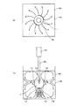
まず、本発明の第1の実施形態に係る攪拌用回転体1の構造について説明する。図1(a)は、攪拌用回転体1の一例を示した平面図であり、同図(b)は、攪拌用回転体1の一例を示した正面図(側面図も同一)であり、同図(c)は、攪拌用回転体1の一例を示した底面図である。これらの図に示されるように、攪拌用回転体1は、略砲弾形状の本体10と、本体10の表面に設けられた複数の吸入口12と、本体10の表面に設けられた複数の吐出口14と、吸入口12と吐出口14を繋ぐように本体10の内部に形成された流通路16から構成されている。
<First Embodiment>
First, the structure of the stirring rotating body 1 according to the first embodiment of the present invention will be described. FIG. 1A is a plan view showing an example of the stirring rotator 1, and FIG. 1B is a front view showing an example of the stirring rotator 1 (the side view is the same). FIG. 3C is a bottom view showing an example of the rotating body 1 for stirring. As shown in these drawings, the stirring rotating body 1 includes a substantially shell-shaped main body 10, a plurality of suction ports 12 provided on the surface of the main body 10, and a plurality of discharges provided on the surface of the main body 10. The outlet 14 is composed of a flow passage 16 formed in the main body 10 so as to connect the suction port 12 and the discharge port 14.

本体10は、この例では、略砲弾形状、詳細には円柱の一方の底面10bを球面状に構成した形状、換言すれば円柱と半球を組み合わせた形状となっている。本体10の他方の底面10aの中心には、モータ等の駆動装置の駆動軸20が接続される接続部18が設けられている。従って、攪拌用回転体1は、本体10の中心軸Cを回転軸として回転するように構成されている。なお、駆動軸20と接続部18の接続方法は、例えばネジや係合等、既知のいずれの方法であってもよい。   In this example, the main body 10 has a substantially bullet shape, specifically, a shape in which one bottom surface 10b of the cylinder is formed into a spherical shape, in other words, a shape in which a cylinder and a hemisphere are combined. At the center of the other bottom surface 10a of the main body 10, a connecting portion 18 to which a driving shaft 20 of a driving device such as a motor is connected is provided. Therefore, the stirring rotating body 1 is configured to rotate about the central axis C of the main body 10 as a rotation axis. In addition, the connection method of the drive shaft 20 and the connection part 18 may be any known method such as a screw or engagement.

本実施形態では、本体10を流通路16以外の部分を中実に構成することで、本体10の強度を高めるようにしている。本体10を構成する材質は、特に限定されるものではなく、例えば金属やセラミックス、樹脂、ゴム、木材等、使用条件に応じた適宜の材質を採用することができる。本実施形態の本体10は、シンプルで加工しやすい形態となっているため、製造方法に制限されることなく、多種多様な材質から本体10を構成することが可能となっている。   In this embodiment, the strength of the main body 10 is increased by configuring the main body 10 other than the flow passage 16 to be solid. The material which comprises the main body 10 is not specifically limited, For example, a suitable material according to use conditions, such as a metal, ceramics, resin, rubber | gum, wood, etc., is employable. Since the main body 10 of the present embodiment is simple and easy to process, the main body 10 can be configured from a wide variety of materials without being limited by the manufacturing method.

また、本体10をこのようにシンプルな形状に構成することより、回転軸に対する不釣合いの発生を少なくすることができる。このため、本実施形態では、不釣合いの発生しやすい羽根車等とは異なり、回転時の振動や振れ回り等を略解消することが可能となっている。   Further, since the main body 10 is configured in such a simple shape, the occurrence of unbalance with respect to the rotating shaft can be reduced. For this reason, in the present embodiment, unlike an impeller or the like that tends to cause unbalance, it is possible to substantially eliminate vibrations and whirling during rotation.

吸入口12は、本体10における接続部18の反対側の底面10b(すなわち、本体10の先端部)に設けられている。本実施形態では、4つの吸入口12を中心軸Cを中心とする円周上に等間隔で並べて配置すると共に、中心軸Cと同一方向に形成している。吐出口14は、本体10の側面10cに設けられている。本実施形態では、4つの吐出口14を、各吸入口12に対して本体10の半径方向(遠心方向)外側となる位置(中心軸Cから中心軸Cに垂直な方向に離れた位置)にそれぞれ配置している。また、中心軸Cに対して直交する方向に吐出口14を形成している。   The suction port 12 is provided on the bottom surface 10 b of the main body 10 on the side opposite to the connection portion 18 (that is, the tip of the main body 10). In the present embodiment, the four suction ports 12 are arranged at equal intervals on a circumference centered on the central axis C, and are formed in the same direction as the central axis C. The discharge port 14 is provided on the side surface 10 c of the main body 10. In the present embodiment, the four discharge ports 14 are positioned at positions outside the main body 10 in the radial direction (centrifugal direction) with respect to the respective suction ports 12 (positions separated from the central axis C in a direction perpendicular to the central axis C). Each is arranged. Further, the discharge port 14 is formed in a direction orthogonal to the central axis C.

吸入口12および吐出口14の形状(断面形状)は特に限定されるものではないが、本実施形態の攪拌用回転体1は、吐出口14を長孔に構成することを特徴としている。詳細には、この例の吐出口14は、同図(b)に示されるように、吐出口14の断面に垂直な方向から見た場合に、中心軸C方向(または、中心軸C方向と平行な方向)を長手方向とする長円形状に形成されている。詳細は後述するが、このように吐出口14を長孔に構成することにより、攪拌能力を向上または調整することが可能となっている。なお、本実施形態では、吸入口12を円形に構成しているが、長孔以外の形状であればその他の形状であってもよい。   The shapes (cross-sectional shapes) of the suction port 12 and the discharge port 14 are not particularly limited, but the stirring rotator 1 of the present embodiment is characterized in that the discharge port 14 is configured as a long hole. Specifically, the discharge port 14 of this example has a central axis C direction (or a central axis C direction) when viewed from a direction perpendicular to the cross section of the discharge port 14 as shown in FIG. It is formed in an oval shape with the parallel direction as the longitudinal direction. Although details will be described later, the stirring ability can be improved or adjusted by configuring the discharge port 14 to be a long hole in this manner. In addition, in this embodiment, although the inlet 12 is comprised circularly, as long as it is shapes other than a long hole, other shapes may be sufficient.

流通路16は、1つの吸入口12と1つの吐出口14を繋ぐ通路として形成されている。従って、本体10の内部には、4つの流通路16が形成されている。各流通路16は、吸入口12から中心軸C方向に沿って直進した後に直角に曲がり、本体10の遠心方向に向けて直進して吐出口14に到達するように形成されている。すなわち、本実施形態の流通路16は、中心軸C方向の軸方向部分16aおよび遠心方向の遠心方向部分16bから構成されている。   The flow passage 16 is formed as a passage connecting one suction port 12 and one discharge port 14. Accordingly, four flow passages 16 are formed inside the main body 10. Each flow passage 16 is formed so as to be straight from the suction port 12 along the direction of the central axis C, then bend at a right angle, and straight forward in the centrifugal direction of the main body 10 to reach the discharge port 14. That is, the flow path 16 of this embodiment is comprised from the axial direction part 16a of the central axis C direction, and the centrifugal direction part 16b of the centrifugal direction.

本実施形態では、流通路16をこのように構成することで、ドリル等による穴加工で容易に吸入口12、吐出口14および流通路16を形成できるようにしている。具体的には、吸入口12の位置から中心軸C方向に沿った穴加工、および吐出口14の位置から中心軸Cに向けた穴加工によって容易に吸入口12、吐出口14および流通路16を形成することができる。   In the present embodiment, the flow passage 16 is configured in this manner, so that the suction port 12, the discharge port 14, and the flow passage 16 can be easily formed by drilling with a drill or the like. Specifically, the suction port 12, the discharge port 14, and the flow passage 16 can be easily formed by drilling a hole from the position of the suction port 12 in the direction of the central axis C and drilling a hole from the position of the discharge port 14 toward the central axis C. Can be formed.

なお、流通路16の断面形状は、特に限定されるものではなく、吸入口12および吐出口14の形状(断面形状)や位置、または加工方法等に応じて適宜の形状に構成することができる。   The cross-sectional shape of the flow passage 16 is not particularly limited, and can be configured in an appropriate shape according to the shape (cross-sectional shape) and position of the suction port 12 and the discharge port 14 or the processing method. .

また、本実施形態では、加工のしやすさから流通路16を略直角に曲折するL字状に構成しているが、これに限定されるものではなく、滑らかに湾曲した曲線状の通路として流通路16を構成してもよいし、吸入口12と吐出口14を一直線状に繋ぐように流通路16を構成してもよい。流通路16をこのように構成することで、流通路16内の流動抵抗を減少させることができるため、攪拌用回転体1が引き起こす流動をさらに強力にし、攪拌能力を向上させることができる。   In the present embodiment, the flow passage 16 is formed in an L shape that bends at a substantially right angle for ease of processing. However, the present invention is not limited to this, and the curved passage is smoothly curved. The flow path 16 may be configured, or the flow path 16 may be configured to connect the suction port 12 and the discharge port 14 in a straight line. By configuring the flow passage 16 in this way, the flow resistance in the flow passage 16 can be reduced, so that the flow caused by the stirring rotor 1 can be further strengthened and the stirring ability can be improved.

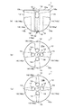
次に、攪拌用回転体1の作動について説明する。図2(a)は攪拌用回転体1の作動を示した平面図であり、同図(b)は攪拌用回転体1の作動を示した正面図である。また、同図(c)は、吐出口14を拡大して示した図である。攪拌用回転体1は、流体である被攪拌物内において、駆動軸20に駆動されて中心軸Cを中心に回転することにより、被攪拌物を攪拌する。   Next, the operation of the stirring rotating body 1 will be described. FIG. 2A is a plan view showing the operation of the stirring rotator 1, and FIG. 2B is a front view showing the operation of the stirring rotator 1. FIG. 2C is an enlarged view of the discharge port 14. The stirring rotating body 1 is driven by the drive shaft 20 and rotates about the central axis C in the object to be stirred that is a fluid, thereby stirring the object to be stirred.

流体中に攪拌用回転体1を浸漬して回転させると、流通路16内に進入した流体も攪拌用回転体1と共に回転することとなる。すると、流通路16内の流体に遠心力が作用し、これらの図に示されるように、流通路16内の流体は攪拌用回転体1の半径方向外側に向けて流動する。吐出口14は、吸入口12よりも本体10の半径方向外側に設けられているため、吐出口14では吸入口12よりも強い遠心力が働くこととなる。従って、流体は、攪拌用回転体1が回転している限り吸入口12から吐出口14に向けて流動する。すなわち、流通路16内の流体が吐出口14から噴出すると共に、外部の流体が吸入口12から流通路16内に吸引される。これにより、攪拌用回転体1の周囲の流体には、吐出口14のある側面10cから放射状に広がる流動と、吸入口12のある攪拌用回転体1の先端部に向かう流動が発生することとなる。なお、攪拌用回転体1の先端部に向かう流動は、吸入口12の回転により旋回流となる。   When the stirring rotator 1 is immersed in the fluid and rotated, the fluid that has entered the flow passage 16 also rotates together with the stirring rotator 1. Then, centrifugal force acts on the fluid in the flow passage 16, and the fluid in the flow passage 16 flows toward the outside in the radial direction of the stirring rotating body 1 as shown in these drawings. Since the discharge port 14 is provided on the radially outer side of the main body 10 with respect to the suction port 12, a stronger centrifugal force acts on the discharge port 14 than on the suction port 12. Accordingly, the fluid flows from the suction port 12 toward the discharge port 14 as long as the stirring rotator 1 rotates. That is, the fluid in the flow passage 16 is ejected from the discharge port 14, and the external fluid is sucked into the flow passage 16 from the suction port 12. Thereby, in the fluid around the stirring rotator 1, a flow that radiates from the side surface 10 c where the discharge port 14 is provided and a flow toward the tip of the stirring rotator 1 that includes the suction port 12 are generated. Become. The flow toward the tip of the stirring rotator 1 becomes a swirling flow by the rotation of the suction port 12.

また、流体中に攪拌用回転体1を浸漬して回転させると、攪拌用回転体1の表面近傍の流体が粘性の影響により攪拌用回転体1と共に回転することとなる。従って、攪拌用回転体1の表面近傍の流体にも遠心力が働き、これらの図に示されるように、表面近傍の流体は攪拌用回転体1の表面に沿って側面10cまで流動し、吐出口14からの噴流の随伴流となる。   Further, when the stirring rotator 1 is immersed in the fluid and rotated, the fluid near the surface of the stirring rotator 1 rotates together with the stirring rotator 1 due to the influence of viscosity. Accordingly, the centrifugal force also acts on the fluid near the surface of the stirring rotator 1, and as shown in these drawings, the fluid near the surface flows along the surface of the stirring rotator 1 to the side surface 10c and discharges it. It becomes an accompanying flow of the jet from the outlet 14.

本実施形態では、底面10bを球面状に構成することにより、本体10の形状を中心軸C方向の厚みが半径方向外側に向けて漸次減少する形状としているため、攪拌用回転体1の底面10b近傍の流動を、側面10cから放射状に広がる流動にスムーズに合流させることを可能としている。また、底面10bをこのような形状にすることで、攪拌用回転体1の先端に向かう流動の一部を、底面10bに沿って側面10cまでスムーズに流動させて、側面10cから放射状に広がる流動に合流させることを可能としている。この結果、攪拌用回転体1は、周囲の流体に強力な流動を発生させ、効率的な攪拌を行うことが可能となっている。   In the present embodiment, since the bottom surface 10b is formed in a spherical shape, the shape of the main body 10 has a shape in which the thickness in the direction of the central axis C gradually decreases outward in the radial direction. The nearby flow can be smoothly merged with the flow spreading radially from the side surface 10c. Further, by forming the bottom surface 10b in such a shape, a part of the flow toward the tip of the stirring rotator 1 smoothly flows to the side surface 10c along the bottom surface 10b, and the flow spreads radially from the side surface 10c. It is possible to join. As a result, the stirring rotator 1 can generate a powerful flow in the surrounding fluid and perform efficient stirring.

さらに、本実施形態では、吐出口14を、中心軸C方向を長手方向とする長孔とすることにより、中心軸C方向の広い範囲にわたって放射状の流動を発生させることを可能としている。すなわち、吐出口14から中心軸C方向に幅広い噴流を発生させることにより、攪拌用回転体1から放射状に広がる流動の中心軸C方向の範囲を広げることが可能となっている。   Further, in the present embodiment, the discharge port 14 is a long hole whose longitudinal direction is the direction of the central axis C, so that radial flow can be generated over a wide range in the direction of the central axis C. That is, by generating a wide jet from the discharge port 14 in the direction of the central axis C, it is possible to widen the range in the direction of the central axis C of the flow that spreads radially from the rotating body 1 for stirring.

吐出口14からの噴流の幅を広げるためには、吐出口14を拡大すればよいが、単に拡大しただけでは、吐出口14からの噴流の流速が低下してしまうため、攪拌能力が低下してしまう場合がある。そこで、本実施形態では、吐出口14を長孔に構成することにより、噴流の幅を広げながらも、流速が低下しないようにしている。すなわち、同図(c)に示されるように、噴流の範囲に応じて吐出口14の長手方向寸法Lを設定した後に、短手方向寸法Sによって吐出口14の断面積を調整することで、適宜の流速を保つようにしている。   In order to widen the width of the jet flow from the discharge port 14, the discharge port 14 may be enlarged. However, if the flow rate is simply increased, the flow velocity of the jet flow from the discharge port 14 is reduced, so that the stirring ability is reduced. May end up. Therefore, in the present embodiment, the discharge port 14 is configured as a long hole so that the flow velocity is not lowered while the width of the jet is widened. That is, as shown in FIG. 5C, after setting the longitudinal dimension L of the discharge port 14 according to the range of the jet flow, by adjusting the cross-sectional area of the discharge port 14 by the short dimension S, An appropriate flow rate is maintained.

このようにすることで、流速を低下させることなく攪拌用回転体1から放射状に広がる流動の範囲を広げることが可能となるため、従来以上に攪拌能力を向上させることができる。また、吐出口14の長手方向寸法Lおよび短手方向寸法Sを調整することにより、攪拌能力を適宜に調整することが可能となる。   By doing in this way, since it becomes possible to expand the range of the flow which spreads radially from the rotating body 1 for stirring without reducing the flow rate, the stirring ability can be improved more than before. Further, by adjusting the longitudinal dimension L and the transverse dimension S of the discharge port 14, the stirring ability can be appropriately adjusted.

なお、吸入口12に対して吐出口14を回転方向にずらして配置し、流通路16の吐出口14へ繋がる部分を攪拌用回転体1の遠心方向に対して角度を有するように構成してもよい。また、吐出口14を中心軸C方向にずらして配置し、流通路16の吐出口14へ繋がる部分を本体10の先端側(接続部18の反対側)、または駆動軸側(接続部18側)に向けるようにしてもよい。このようにして、吐出口14からの噴出方向を適宜に設定することにより、効率的な攪拌に最も適した流動を得ることができる。また、複数の吐出口14に対して1つの吸入口12を設け、流通路16を1つの吸入口12から複数の吐出口14に分岐するように構成してもよい。   In addition, the discharge port 14 is arranged so as to be shifted in the rotational direction with respect to the suction port 12, and the portion connected to the discharge port 14 of the flow passage 16 is configured to have an angle with respect to the centrifugal direction of the stirring rotating body 1. Also good. Further, the discharge port 14 is arranged in the direction of the central axis C, and the portion of the flow passage 16 connected to the discharge port 14 is the tip side of the main body 10 (the side opposite to the connection portion 18) or the drive shaft side (the connection portion 18 side). ). Thus, the flow most suitable for efficient stirring can be obtained by appropriately setting the ejection direction from the discharge port 14. Alternatively, one suction port 12 may be provided for the plurality of discharge ports 14, and the flow path 16 may be branched from the one suction port 12 to the plurality of discharge ports 14.

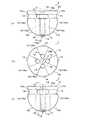
図3(a)および(b)は、攪拌用回転体1の使用例を示した概略図である。これらの図に示されるように、攪拌用回転体1は、モータ等の駆動装置30に繋がる駆動軸20に接続され、容器40内に収容された流体である被攪拌物50内に浸漬された状態で使用される。駆動装置30は、容器40や架台等に固定されるものであってもよいし、使用者が保持して操作するものであってもよい。   FIGS. 3A and 3B are schematic views showing an example of use of the stirring rotator 1. As shown in these drawings, the stirring rotating body 1 is connected to a driving shaft 20 connected to a driving device 30 such as a motor, and is immersed in an object to be stirred 50 that is a fluid contained in a container 40. Used in state. The driving device 30 may be fixed to the container 40, a pedestal, or the like, or may be held and operated by a user.

駆動装置30によって攪拌用回転体1を回転させることにより、上述のように攪拌用回転体1から放射状に広がる流動、および攪拌用回転体1の先端部に向かう旋回流(渦)が発生する。これにより、同図(a)および(b)に示されるように、被攪拌物50内に複雑な循環流が発生し、この循環流により被攪拌物50は十分に攪拌される。   By rotating the stirring rotator 1 by the driving device 30, a flow radially spreading from the stirring rotator 1 and a swirling flow (vortex) toward the tip of the stirring rotator 1 are generated as described above. As a result, as shown in FIGS. 4A and 4B, a complicated circulation flow is generated in the stirring object 50, and the stirring object 50 is sufficiently stirred by this circulation flow.

容器40の底に滞留している滞留物を分散させる場合には、攪拌用回転体1の先端部を容器40の底に近づければよい。このようにすることで、吸入口12から滞留物を吸い上げて吐出口14から噴出し、滞留物を被攪拌物50内に十分に分散させることができる。また、容器40の角部に滞留している滞留物を分散させる場合には、攪拌用回転体1の先端部を容器40の角部に近づければよい。本実施形態では、本体10を略砲弾形状に構成しているため、狭隘な角部にも吸入口12を十分に近づけることができる。   In order to disperse the staying matter staying at the bottom of the container 40, the tip of the stirring rotor 1 may be brought close to the bottom of the container 40. By doing so, the staying material can be sucked up from the suction port 12 and ejected from the discharge port 14, and the staying material can be sufficiently dispersed in the stirring object 50. In addition, when the accumulated matter staying at the corner of the container 40 is dispersed, the tip of the stirring rotating body 1 may be brought close to the corner of the container 40. In the present embodiment, since the main body 10 is configured in a substantially bullet shape, the suction port 12 can be sufficiently brought close to a narrow corner portion.

本実施形態では、本体10を略砲弾形状に構成することにより、回転時に被攪拌物50と衝突しないようにしているため、回転開始時の反動がほとんど生じないようになっている。また、羽根車等とは異なり、本体10に鋭利な突起物を備えていないことから、攪拌用回転体1を容器40の壁面にぶつけた場合にも攪拌用回転体1または容器40が破損したり削れたりする可能性が低くなっている。このため、安心して攪拌用回転体1を容器40の壁面に近づけることができ、容器40の隅々まで十分に攪拌を行うことが可能であると共に、攪拌用回転体1または容器40の破片や削りカス等が被攪拌物50に混入し難いようになっている。   In the present embodiment, the main body 10 is configured in a substantially bullet shape so that it does not collide with the agitated object 50 during rotation, so that almost no reaction occurs at the start of rotation. In addition, unlike the impeller and the like, the main body 10 is not provided with a sharp protrusion, and therefore the stirring rotator 1 or the container 40 is damaged even when the stirring rotator 1 is hit against the wall surface of the container 40. The possibility of scraping or scraping is low. For this reason, the rotating body 1 for stirring can be brought close to the wall surface of the container 40 with peace of mind, and it is possible to sufficiently stir all the corners of the container 40. It is difficult for scrap and the like to be mixed into the object to be stirred 50.

また、本実施形態では、攪拌用回転体1の先端部中心(回転軸である中心軸C)のやや外側に吸入口12を配置することにより、攪拌用回転体1の先端部を容器40の壁面に接触させた場合にも吸入口12が塞がれないようにしている。このため、容器40の壁面近くにおいても安定して攪拌用回転体1を操作することができる。   In the present embodiment, the suction port 12 is disposed slightly outside the center of the tip of the stirring rotator 1 (center axis C, which is the rotation axis), so that the tip of the stirring rotator 1 is placed on the container 40. The suction port 12 is prevented from being blocked even when it is brought into contact with the wall surface. For this reason, the rotating body 1 for stirring can be stably operated even near the wall surface of the container 40.

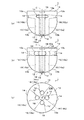
次に、攪拌用回転体1のその他の形態について説明する。まず図4(a)〜(c)は、流通路16を吐出口14に向けて漸次拡大または縮小するように構成した例を示した図である。なお、同図(a)は、正面図(側面図)であり、同図(b)および(c)は、底面図である。   Next, other forms of the stirring rotor 1 will be described. First, FIGS. 4A to 4C are diagrams showing an example in which the flow passage 16 is configured to gradually expand or contract toward the discharge port 14. In addition, the figure (a) is a front view (side view), and the figure (b) and (c) are bottom views.

本実施形態では、吐出口14を吸入口12とは異なる形状の長孔に構成しているため、流通路16の断面形状を途中で変化させる必要がある。この場合に、吐出口14の長手方向寸法Lおよび短手方向寸法Sに合わせて、流通路16の少なくとも一部を漸次拡大または縮小するように構成することにより、流通路16内のよどみを解消し、流動をスムーズにすることができる。   In this embodiment, since the discharge port 14 is configured as a long hole having a shape different from that of the suction port 12, the cross-sectional shape of the flow passage 16 needs to be changed midway. In this case, the stagnation in the flow path 16 is eliminated by configuring the flow path 16 so as to gradually expand or contract in accordance with the longitudinal dimension L and the short dimension S of the discharge port 14. The flow can be made smooth.

ここで、同図(a)は、吐出口14の長手方向寸法Lに合わせて、流通路16の遠心方向部分16bを漸次拡大した例を示している。また、同図(b)は、吐出口14の短手方向寸法Sに合わせて流通路16の遠心方向部分16bを漸次拡大した例を、同図(c)は、吐出口14の短手方向寸法Sに合わせて流通路16の遠心方向部分16bを漸次縮小した例を示している。なお、流通路16の軸方向部分16aを、漸次拡大または縮小するようにしてもよいことは言うまでもない。   Here, FIG. 5A shows an example in which the centrifugal direction portion 16b of the flow passage 16 is gradually enlarged in accordance with the longitudinal dimension L of the discharge port 14. FIG. 4B shows an example in which the centrifugal direction portion 16b of the flow passage 16 is gradually enlarged in accordance with the short-side dimension S of the discharge port 14, and FIG. The example which reduced gradually the centrifugal direction part 16b of the flow path 16 according to the dimension S is shown. Needless to say, the axial portion 16a of the flow passage 16 may be gradually enlarged or reduced.

図5(a)〜(c)および図6(a)〜(c)は、吐出口14を中心軸Cに直交する方向を長手方向とする長孔に構成した例を示した図である。なお、図5(a)および(c)ならびに図6(a)および(b)は、正面図(側面図)であり、図5(b)ならびに図6(c)は、底面図である。   FIGS. 5A to 5C and FIGS. 6A to 6C are diagrams showing an example in which the discharge port 14 is configured as a long hole whose longitudinal direction is a direction orthogonal to the central axis C. FIG. FIGS. 5A and 5C and FIGS. 6A and 6B are front views (side views), and FIGS. 5B and 6C are bottom views.

この例の吐出口14は、詳細には図5(a)に示されるように、吐出口14の断面に垂直な方向から見た場合に、中心軸Cに直交する方向を長手方向とする長円形状に形成されている。攪拌用回転体1の用途によっては、吐出口14をこのような長孔に構成することにより、効率的な攪拌を行うことができる。   As shown in detail in FIG. 5A, the discharge port 14 of this example is a length having a direction perpendicular to the central axis C as a longitudinal direction when viewed from a direction perpendicular to the cross section of the discharge port 14. It is formed in a circular shape. Depending on the application of the rotating body 1 for agitation, efficient agitation can be performed by configuring the discharge port 14 in such a long hole.

例えば、被攪拌物50の液面を波立たせることなく効率的な攪拌を行う必要がある場合、攪拌用回転体1の先端部(すなわち吸入口12)に向かう旋回流の強さを維持しつつ、攪拌用回転体1から放射状に広がる流動を弱めることが効果的である。   For example, when it is necessary to perform efficient stirring without making the liquid level of the object to be stirred 50 undulate, the strength of the swirl flow toward the front end portion (that is, the suction port 12) of the rotating body 1 for stirring is maintained. On the other hand, it is effective to weaken the flow spreading radially from the rotating body 1 for stirring.

このような場合、吐出口14を、中心軸Cに直交する方向を長手方向とする長孔に構成すれば、吐出口14を攪拌用回転体1の回転方向に拡大(延長)することとなるため、攪拌用回転体1から放射状に広がる流動の中心軸C方向の範囲を広げることなく、流速を低下させることができる。そして、吸入口12と吐出口14の断面積比を適宜に設定すれば、攪拌用回転体1の先端部に向かう旋回流の強さを維持することができる。   In such a case, if the discharge port 14 is configured as a long hole whose longitudinal direction is the direction orthogonal to the central axis C, the discharge port 14 is expanded (extended) in the rotation direction of the stirring rotor 1. Therefore, the flow velocity can be reduced without expanding the range in the direction of the central axis C of the flow that spreads radially from the rotating body 1 for stirring. If the cross-sectional area ratio between the suction port 12 and the discharge port 14 is set appropriately, the strength of the swirling flow toward the tip of the stirring rotator 1 can be maintained.

この例においても、攪拌用回転体1から放射状に広がる流動の強さおよび範囲は、吐出口14の長手方向寸法Lおよび短手方向寸法Sを適宜に設定することにより、調整することができる。また、図5(b)および(c)ならびに図6(a)に示されるように、吐出口14の長手方向寸法Lおよび短手方向寸法Sに合わせて、流通路16の少なくとも一部を漸次拡大または縮小するように構成することにより、流通路16内の流動をスムーズにすることができる。   Also in this example, the strength and range of the flow that radiates from the stirring rotator 1 can be adjusted by appropriately setting the longitudinal dimension L and the transverse dimension S of the discharge port 14. Further, as shown in FIGS. 5B and 5C and FIG. 6A, at least a part of the flow passage 16 is gradually formed in accordance with the longitudinal dimension L and the transverse dimension S of the discharge port 14. By being configured to expand or contract, the flow in the flow passage 16 can be made smooth.

なお、図5(b)は、吐出口14の長手方向寸法Lに合わせて、流通路16の遠心方向部分16bを漸次拡大した例を示している。また、図5(c)は、吐出口14の短手方向寸法Sに合わせて流通路16の遠心方向部分16bを漸次拡大した例を、図6(a)は、吐出口14の短手方向寸法Sに合わせて流通路16の遠心方向部分16bを漸次縮小した例を示している。   FIG. 5B shows an example in which the centrifugal direction portion 16 b of the flow passage 16 is gradually enlarged in accordance with the longitudinal dimension L of the discharge port 14. 5C shows an example in which the centrifugal direction portion 16b of the flow passage 16 is gradually enlarged in accordance with the short dimension S of the discharge port 14, and FIG. 6A shows the short direction of the discharge port 14. The example which reduced gradually the centrifugal direction part 16b of the flow path 16 according to the dimension S is shown.

図6(b)および(c)は、吸入口12の位置に対する吐出口14の位置を回転方向にずらして配置した例を示している。このように吐出口14の位置をずらすことにより、吐出口14からの噴流の方向を適宜に変化させることができるため、攪拌用回転体1から放射状に広がる流動の状態を、より細かく調整することができる。   6B and 6C show an example in which the position of the discharge port 14 with respect to the position of the suction port 12 is shifted in the rotational direction. By shifting the position of the discharge port 14 in this way, the direction of the jet flow from the discharge port 14 can be appropriately changed, so that the state of the flow spreading radially from the rotating body for stirring 1 can be adjusted more finely. Can do.

図7(a)〜(c)は、吐出口14のその他の形態の例を示した正面図(側面図)である。同図(a)は、吐出口14を、吐出口14の断面に垂直な方向から見た場合に、中心軸Cに対して角度を有する方向を長手方向とする長円形状に形成した例を示している。このように、吐出口14を中心軸Cに対して斜めに配置することにより、攪拌用回転体1の回転と相俟って吐出口14からの噴流をより複雑な流れにすることが可能となるため、攪拌能力を向上させることができる。すなわち、本実施形態では、長孔に構成した吐出口14の長手方向寸法Lおよび短手方向寸法Sと共に、長手方向の向きを調整することによって、攪拌能力を適宜に調整することが可能となっている。   FIGS. 7A to 7C are front views (side views) showing examples of other forms of the discharge port 14. FIG. 4A shows an example in which the discharge port 14 is formed in an oval shape having a direction having an angle with respect to the central axis C as a longitudinal direction when viewed from a direction perpendicular to the cross section of the discharge port 14. Show. Thus, by arranging the discharge port 14 obliquely with respect to the central axis C, the jet flow from the discharge port 14 can be made a more complicated flow in combination with the rotation of the rotating body 1 for stirring. Therefore, the stirring ability can be improved. That is, in the present embodiment, the stirring ability can be appropriately adjusted by adjusting the longitudinal direction along with the longitudinal dimension L and the transverse dimension S of the discharge port 14 configured as a long hole. ing.

同図(b)は、吐出口14を長方形状に構成した例を示している。また、同図(c)は、吐出口14を円弧状に湾曲した長円形状に構成した例を示している。このように、吐出口14の形状は、上述の例で示した長円形状以外にも、長方形状や楕円形状、多角形状等、長孔となる種々の形状を採用することができる。また、吐出口14の形状は、長円形や長方形等が湾曲した形状であってもよい。なお、吐出口14を湾曲した形状とする場合、円弧状の他に、U字状、V字状、W字状、またはS字状等に湾曲した形状であってもよい。   FIG. 2B shows an example in which the discharge port 14 is formed in a rectangular shape. FIG. 3C shows an example in which the discharge port 14 is formed in an oval shape curved in an arc shape. Thus, the shape of the discharge port 14 can employ various shapes such as a rectangular shape, an elliptical shape, and a polygonal shape other than the oval shape shown in the above example. Moreover, the shape of the discharge port 14 may be a shape in which an oval, a rectangle, or the like is curved. When the discharge port 14 has a curved shape, it may have a U-shaped, V-shaped, W-shaped, or S-shaped shape in addition to the arc shape.

図8(a)は、駆動軸側に吸入口12を設けた例を示した正面図(側面図)である。同図は、4つの吸入口12のうち、2つの吸入口12を駆動軸側の底面10aに設けた例を示している。吸入口12は、このように複数の吸入口12の一部を先端側に配置し、残りの一部を駆動軸側に配置するようにしてもよい。また、用途によっては、全ての吸入口12を駆動軸側に設けるようにしてもよい。   FIG. 8A is a front view (side view) showing an example in which the suction port 12 is provided on the drive shaft side. The figure shows an example in which two of the four suction ports 12 are provided on the bottom surface 10a on the drive shaft side. As described above, the suction port 12 may be configured such that a part of the plurality of suction ports 12 is disposed on the distal end side and the remaining part is disposed on the drive shaft side. Further, depending on the application, all of the suction ports 12 may be provided on the drive shaft side.

吸入口12の配置を適宜に設定することで、用途に応じた最適な流動を発生させるようにすることができる。また、駆動軸側の吸入口12を流体の液面に近づけて流体外部の気体を吸引するようにすれば、流体中に積極的に外部の気体を取り込むことができる。これにより、流体中に気体を溶け込ませたり、流体中に気泡を混入させたりすることができる。   By appropriately setting the arrangement of the suction port 12, it is possible to generate an optimal flow according to the application. Further, if the suction port 12 on the drive shaft side is brought close to the liquid surface of the fluid to suck the gas outside the fluid, the outside gas can be actively taken into the fluid. Thereby, gas can be dissolved in the fluid or bubbles can be mixed in the fluid.

なお、本体10に被攪拌物50の外部の気体を吸引するための専用の吸気口を設けると共に、この吸気口と吐出口14を繋ぐ通気路を設けるようにしてもよい。このように、本体10に吸気口および通気路を設けた場合、吸気口を流体外部に露出させた状態または流体外部の気体に触れる状態で攪拌用回転体1を回転させることにより、容易に流体中に気体を溶け込ませたり、流体中に気泡を混入させたりすることができる。   The main body 10 may be provided with a dedicated intake port for sucking the gas outside the object to be stirred 50, and an air passage connecting the intake port and the discharge port 14 may be provided. As described above, when the main body 10 is provided with the air inlet and the air passage, the fluid can be easily obtained by rotating the stirring rotating body 1 in a state where the air inlet is exposed to the outside of the fluid or in contact with a gas outside the fluid. Gases can be dissolved therein, or bubbles can be mixed into the fluid.

図8(b)は、攪拌用回転体1を異物の捕獲が可能に構成した例を示した正面図(側面図)である。同図では、流通路16の吐出口14近傍にゴミ等の異物捕獲用のフィルタ60を設けた例を示している。このように、流通路16の途中にフィルタ60を設けることにより、被攪拌物50中に含まれる異物の除去を攪拌と同時に行うことが可能となる。フィルタ60は、例えば金網やスポンジ等、用途に応じた材質から構成すればよい。なお、フィルタ60を配置する位置は、同図(a)に示す位置に限定されるものではなく、その他の位置であってもよい。   FIG. 8B is a front view (side view) showing an example in which the stirring rotator 1 is configured to be able to capture foreign matter. In the figure, an example in which a filter 60 for capturing foreign matter such as dust is provided in the vicinity of the discharge port 14 of the flow passage 16 is shown. Thus, by providing the filter 60 in the middle of the flow passage 16, it is possible to remove foreign substances contained in the object to be stirred 50 simultaneously with stirring. The filter 60 may be made of a material according to the application, such as a wire mesh or sponge. Note that the position where the filter 60 is disposed is not limited to the position shown in FIG.

本実施形態では、吐出口14を長孔に構成しているため、吐出口14の長手方向寸法L、短手方向寸法S、および長手方向の向きを適宜に設定することにより、本体10の大きさや形状によらず、吐出口14およびその近傍の流通路16の断面積を、効率的な異物の捕獲に必要な断面積にすることが可能となっている。すなわち、本実施形態によれば、上述したような攪拌能力の向上や調整だけではなく、異物捕獲能力も向上させることができる。   In the present embodiment, since the discharge port 14 is configured as a long hole, the size of the main body 10 can be increased by appropriately setting the longitudinal dimension L, the short dimension S, and the longitudinal direction of the discharge port 14. Regardless of the shape of the sheath, the cross-sectional area of the discharge port 14 and the flow passage 16 in the vicinity thereof can be set to a cross-sectional area necessary for efficient capture of foreign matter. That is, according to this embodiment, not only the improvement and adjustment of the stirring ability as described above, but also the foreign matter capturing ability can be improved.

図8(c)は、本体10を球状に構成した例を示した正面図(側面図)である。このように、本体10の形状は、上述の例で示した略砲弾形状に限定されるものではなく、球状、部分球状、楕円体状、部分楕円体状、円柱状、円盤状、円錐状、または円錐台状等であってもよいし、これらの立体を組み合わせて構成される形状であってもよい。   FIG.8 (c) is the front view (side view) which showed the example which comprised the main body 10 in spherical shape. Thus, the shape of the main body 10 is not limited to the substantially shell shape shown in the above-described example, but is a sphere, a partial sphere, an ellipsoid, a partial ellipsoid, a column, a disk, a cone, Or a truncated cone shape etc. may be sufficient and the shape comprised combining these solid bodies may be sufficient.

また、本体10の形状は、安全性や容器等への衝突の点からは、回転軸(中心軸C)に垂直な断面が円形となる上記したような形状であることが好ましいが、本体10の形状はこれに限定されるものではなく、回転軸(中心軸C)に垂直な断面が円形以外となる形状であってもよい。すなわち、本体10の形状は、例えば多角柱状、多角錐状、または多角錐台状等であってもよいし、種々の立体を組み合わせて構成される形状であってもよい。さらに、本体10の表面に複数の凸部や凹部を設けるようにしてもよい。   In addition, the shape of the main body 10 is preferably the above-described shape in which the cross section perpendicular to the rotation axis (center axis C) is circular from the viewpoint of safety and collision with the container or the like. The shape is not limited to this, and the cross section perpendicular to the rotation axis (center axis C) may be other than circular. That is, the shape of the main body 10 may be, for example, a polygonal column shape, a polygonal pyramid shape, or a polygonal frustum shape, or may be a shape configured by combining various solids. Further, a plurality of convex portions and concave portions may be provided on the surface of the main body 10.

このように、本体10を適宜の凹凸を備えた形状に構成することで、攪拌用回転体1の周囲に適度な渦流を発生させることが可能となり、これにより、攪拌能力をさらに向上させることができる場合がある。さらに、本体10の形状の設定に加えて、本体10表面の粗さや、より細かい凹凸形状を適宜に設定することによって、攪拌用回転体1の周囲の流動をより精密に制御するようにしてもよい。また、本体10の表面に各種の彩色を施して意匠性を向上させるようにしてもよい。   Thus, by configuring the main body 10 to have a shape with appropriate irregularities, it becomes possible to generate an appropriate vortex around the stirring rotating body 1, thereby further improving the stirring ability. There are cases where it is possible. Furthermore, in addition to the setting of the shape of the main body 10, the flow around the stirring rotor 1 may be controlled more precisely by appropriately setting the roughness of the surface of the main body 10 and finer uneven shapes. Good. In addition, various colors may be applied to the surface of the main body 10 to improve the design.

<第2の実施形態>
次に、本発明の第2の実施形態に係る攪拌用回転体2について説明する。本実施形態の攪拌用回転体2は、吸入口12を長孔に構成することを特徴としており、その他の基本的な構成および作動は、第1の実施形態と同一である。従って、同一部分については、図中において同一符号を付すと共にその説明を省略し、以下、第1の実施形態と異なる部分についてのみ説明する。
<Second Embodiment>
Next, the stirring rotator 2 according to the second embodiment of the present invention will be described. The rotating body 2 for stirring of the present embodiment is characterized in that the suction port 12 is configured as a long hole, and other basic configurations and operations are the same as those of the first embodiment. Therefore, the same portions are denoted by the same reference numerals in the drawings and the description thereof is omitted, and only portions different from the first embodiment will be described below.

図9(a)は、攪拌用回転体2の一例を示した平面図であり、同図(b)は、攪拌用回転体2の一例を示した正面図(側面図)であり、同図(c)は、攪拌用回転体2の一例を示した底面図である。上述のように、本実施形態の攪拌用回転体2は、吸入口12を長孔に構成することを特徴としている。詳細には、この例の吸入口12は、同図(a)または(c)に示されるように、中心軸C(回転軸)方向から見た場合に、中心軸Cの遠心方向(半径方向)を長手方向とする、長円形状に形成されている。   FIG. 9A is a plan view showing an example of the stirring rotator 2, and FIG. 9B is a front view (side view) showing an example of the stirring rotator 2. (C) is a bottom view showing an example of the rotating body 2 for stirring. As described above, the stirring rotating body 2 of the present embodiment is characterized in that the suction port 12 is configured as a long hole. Specifically, the suction port 12 of this example has a centrifugal direction (radial direction) of the center axis C when viewed from the direction of the center axis C (rotation axis), as shown in FIG. ) In the longitudinal direction.

被攪拌物50中において、攪拌用回転体2の先端部に向かう流動は、吸入口12が本体10と共に回転することによって旋回流となるが、本実施形態では、吸入口12を、中心軸Cの遠心方向を長手方向とする長孔とすることにより、この旋回流を拡大することが可能となっている。   In the object to be stirred 50, the flow toward the tip of the stirring rotating body 2 becomes a swirling flow when the suction port 12 rotates together with the main body 10, but in this embodiment, the suction port 12 is moved to the central axis C. This swirl flow can be expanded by using a long hole whose longitudinal direction is the centrifugal direction.

すなわち、吸入口12をこのような長孔に構成し、長手方向寸法Lおよび短手方向寸法Sを適宜に調整することで、吸入口12に向かう流動の範囲を遠心方向に広げながらも、吸入口12における流速、すなわち吸引力を低下させないようにすることが可能となる。これにより、本実施形態では、被攪拌物50中において、攪拌用回転体2の先端部から先の領域に大きく強い旋回流を発生させることができるため、攪拌能力を向上させることが可能となっている。   That is, the suction port 12 is configured as such a long hole, and the longitudinal dimension L and the short dimension S are appropriately adjusted, so that the range of flow toward the suction port 12 is expanded while the suction direction is expanded. It is possible to prevent the flow rate at the mouth 12, that is, the suction force, from being lowered. Thereby, in this embodiment, in the to-be-stirred object 50, since a big strong swirl | flow can be generated in the area | region ahead from the front-end | tip part of the rotating body 2 for stirring, it becomes possible to improve stirring capability. ing.

また、吸入口12をこのような長孔に構成することで、吸入口12の長手方向両端部における周速および作用する遠心力に差を生じさせることができる。これにより、流通路16内の流動および吐出口14からの噴流に乱れを生じさせることが可能となるため、さらに攪拌能力を向上させることができる。   In addition, by configuring the suction port 12 as such a long hole, a difference can be made in the peripheral speed and the acting centrifugal force at both ends in the longitudinal direction of the suction port 12. Thereby, since it becomes possible to produce disturbance in the flow in the flow passage 16 and the jet flow from the discharge port 14, the stirring ability can be further improved.

なお、本実施形態では、吸入口12を円形に構成しているが、長孔以外の形状であればその他の形状であってもよい。また、流通路16は、吸入口12および吐出口14の寸法に応じて、適宜に漸次拡大または縮小させるようにすることができる。   In addition, in this embodiment, although the inlet 12 is comprised circularly, as long as it is shapes other than a long hole, other shapes may be sufficient. Further, the flow passage 16 can be gradually enlarged or reduced as appropriate according to the dimensions of the suction port 12 and the discharge port 14.

次に、攪拌用回転体2のその他の形態について説明する。図10(a)〜(c)および図11(a)〜(c)は、吸入口12のその他の形態を示した底面図である。図10(a)は、吸入口12を8つ設けた例を示している。作用する遠心力の大きさを考慮すると、吸入口12は、なるべく回転軸である中心軸Cに近づけて配置することが好ましいが、吸入口12を、中心軸Cの遠心方向を長手方向とする長孔とすることにより、中心軸C近傍の狭いスペースに、より多くの吸入口12を配置することが可能となる。すなわち、より多くの吸入口12を、断面積を減少させることなく中心軸Cに近づけて配置すると共に、吸入口12の個数に応じて吐出口14の個数も増やすことが可能となるため、攪拌能力を向上させることができる。   Next, the other form of the rotating body 2 for stirring is demonstrated. FIGS. 10A to 10C and FIGS. 11A to 11C are bottom views showing other forms of the inlet 12. FIG. 10A shows an example in which eight suction ports 12 are provided. In consideration of the magnitude of the acting centrifugal force, the suction port 12 is preferably arranged as close to the central axis C as the rotation axis as much as possible, but the suction port 12 has the centrifugal direction of the central axis C as the longitudinal direction. By using the long holes, it becomes possible to arrange more suction ports 12 in a narrow space near the central axis C. In other words, more suction ports 12 can be arranged close to the central axis C without reducing the cross-sectional area, and the number of discharge ports 14 can be increased according to the number of suction ports 12. Ability can be improved.

同図(b)は、吸入口12を、中心軸C方向から見た場合に、中心軸Cを中心とする円周の接線方向を長手方向とする長円形状に構成した例を示している。また、同図(c)は、吸入口12を、中心軸C方向から見た場合に、中心軸Cを中心とする円周の接線方向に対して角度を有する方向を長手方向とする長円形状に構成した例を示している。   FIG. 4B shows an example in which the suction port 12 is formed in an oval shape with the tangential direction of the circumference around the center axis C as the longitudinal direction when viewed from the direction of the center axis C. . FIG. 10C shows an ellipse whose longitudinal direction is a direction having an angle with respect to a tangential direction of the circumference around the central axis C when the suction port 12 is viewed from the central axis C direction. An example configured in a shape is shown.

このように、長孔に構成した吸入口12の長手方向の向きを調整することにより、攪拌用回転体1の回転と相俟って吸入口12に向かう旋回流の状態を適宜に調整することができる。また、吐出口14からの噴流の乱れの状態を調整することも可能となるため、攪拌能力を調整することができる。すなわち、本実施形態では、長孔に構成した吸入口12の長手方向寸法Lおよび短手方向寸法Sと共に、長手方向の向きを調整することによって、攪拌能力を適宜に調整することが可能となっている。   Thus, by adjusting the longitudinal direction of the suction port 12 configured as a long hole, the state of the swirling flow toward the suction port 12 in combination with the rotation of the stirring rotator 1 is appropriately adjusted. Can do. Moreover, since it becomes possible to adjust the state of the turbulence of the jet flow from the discharge port 14, the stirring ability can be adjusted. That is, in the present embodiment, the stirring ability can be adjusted appropriately by adjusting the longitudinal direction along with the longitudinal dimension L and the transverse dimension S of the suction port 12 configured as a long hole. ing.

図11(a)は、吸入口12を長方形状に構成した例を示している。また、同図(b)および(c)は、吸入口12を円弧状に湾曲した長円形状に構成した例を示している。このように、吸入口12の形状は、長円形状以外にも、長方形状や楕円形状、多角形状等、長孔となる種々の形状を採用することができる。また、吸入口12の形状は、長円形や長方形等が湾曲した形状であってもよく、円弧状の他に、U字状、V字状、W字状、またはS字状等に湾曲した形状であってもよい。   FIG. 11A shows an example in which the suction port 12 is formed in a rectangular shape. FIGS. 7B and 7C show an example in which the suction port 12 is formed in an elliptical shape curved in an arc shape. As described above, the shape of the suction port 12 may employ various shapes such as a rectangular shape, an elliptical shape, a polygonal shape, and the like other than an oval shape. In addition, the shape of the inlet 12 may be an elliptical shape, a rectangular shape, or the like. In addition to an arc shape, the shape of the suction port 12 is curved in a U shape, a V shape, a W shape, or an S shape. It may be a shape.

ここで、同図(b)に示されるように、吸入口12を円弧状に湾曲した形状に構成すると共に、長手方向が中心軸Cを中心とする円周の接線方向となるように配置することにより、断面積を減少させることなく吸入口12を中心軸Cに近づけることができる。また、同図(c)に示されるように、吸入口12を、長手方向が中心軸Cを中心とする円周の接線方向に対して角度を有する方向となるように配置すると共に、適宜に湾曲させることにより、吸入口12に向かう旋回流の状態、および吐出口14からの噴流の乱れの状態をより細かく調整することができる。   Here, as shown in FIG. 5B, the suction port 12 is configured to have an arcuate shape and is arranged so that the longitudinal direction is a tangential direction of the circumference centered on the central axis C. As a result, the suction port 12 can be brought closer to the central axis C without reducing the cross-sectional area. In addition, as shown in FIG. 5C, the suction port 12 is arranged so that the longitudinal direction is at an angle with respect to the tangential direction of the circumference around the central axis C, and appropriately By curving, the state of the swirling flow toward the suction port 12 and the state of the turbulence of the jet flow from the discharge port 14 can be adjusted more finely.

また、図示は省略するが、吸入口12を長孔に構成することにより、吸入口12を中心軸Cに近づけながらも断面積を大きくすることができるため、吸入口12の近傍に異物捕獲用のフィルタ60を設けた場合にも、異物捕獲能力を向上させることができる。   Although not shown in the drawings, by configuring the suction port 12 as a long hole, the cross-sectional area can be increased while bringing the suction port 12 close to the central axis C. Even when the filter 60 is provided, the foreign matter capturing ability can be improved.

<第3の実施形態>
次に、本発明の第3の実施形態に係る攪拌用回転体3について説明する。本実施形態の攪拌用回転体3は、吸入口12および吐出口14をそれぞれ長孔に構成することを特徴としており、その他の基本的な構成および作動は、第1および第2の実施形態と同一である。従って、同一部分については、図中において同一符号を付すと共にその説明を省略し、以下、第1および第2の実施形態と異なる部分についてのみ説明する。
<Third Embodiment>
Next, the stirring rotator 3 according to the third embodiment of the present invention will be described. The rotating body 3 for stirring according to the present embodiment is characterized in that the suction port 12 and the discharge port 14 are respectively formed as long holes, and other basic configurations and operations are the same as those of the first and second embodiments. Are the same. Accordingly, the same portions are denoted by the same reference numerals in the drawings and the description thereof is omitted, and only portions different from the first and second embodiments will be described below.

図12(a)は、攪拌用回転体3の一例を示した平面図であり、同図(b)は、攪拌用回転体3の一例を示した正面図(側面図)であり、同図(c)は、攪拌用回転体3の一例を示した底面図である。上述のように、本実施形態の攪拌用回転体3は、吸入口12および吐出口14をそれぞれ長孔に構成することを特徴としている。   FIG. 12A is a plan view showing an example of the stirring rotator 3, and FIG. 12B is a front view (side view) showing an example of the stirring rotator 3. FIG. (C) is a bottom view showing an example of the rotating body 3 for stirring. As described above, the stirring rotator 3 of the present embodiment is characterized in that the suction port 12 and the discharge port 14 are each formed as a long hole.

同図(a)〜(c)に示す例では、吸入口12は、中心軸C(回転軸)方向から見た場合に、中心軸Cの遠心方向を長手方向とする、長円形状に形成されており、吐出口14は、吐出口14の断面に垂直な方向から見た場合に、中心軸C方向(または、中心軸C方向と平行な方向)を長手方向とする長円形状に形成されているが、吸入口12および吐出口14の形状は、長孔であればその他の形状であってもよい。すなわち、吸入口12および吐出口14の形状は、第1および第2の実施形態で示したような種々の形状を採用することができる。   In the example shown in FIGS. 4A to 4C, the suction port 12 is formed in an oval shape with the centrifugal direction of the central axis C as the longitudinal direction when viewed from the central axis C (rotating axis) direction. The discharge port 14 is formed in an oval shape having a central axis C direction (or a direction parallel to the central axis C direction) as a longitudinal direction when viewed from a direction perpendicular to the cross section of the discharge port 14. However, the shapes of the suction port 12 and the discharge port 14 may be other shapes as long as they are long holes. That is, as the shapes of the suction port 12 and the discharge port 14, various shapes as shown in the first and second embodiments can be adopted.

このように、吸入口12および吐出口14をそれぞれ長孔に構成し、それぞれの長手方向寸法L、短手方向寸法S、および長手方向の向きを適宜に設定することで、攪拌用回転体3の先端部に向かう流動、および攪拌用回転体3から放射状に広がる流動の状態を調整することができる。すなわち、本実施形態では、攪拌用回転体3の攪拌能力を、用途等に応じてより細かく調整することが可能となっている。   In this manner, the suction port 12 and the discharge port 14 are each formed as a long hole, and the longitudinal dimension L, the lateral dimension S, and the direction in the longitudinal direction are appropriately set, whereby the stirring rotator 3 is set. It is possible to adjust the flow toward the front end of the liquid and the state of the flow spreading radially from the rotating body 3 for stirring. That is, in this embodiment, it is possible to finely adjust the stirring ability of the stirring rotator 3 according to the application.

<第4の実施形態>
次に、本発明の第4の実施形態に係る攪拌用回転体4について説明する。本実施形態の攪拌用回転体4は、第1〜3の実施形態の攪拌用回転体1〜3にスライド部材70、80、90を適用したものであり、その他の基本的な構成および作動は、第1〜3の実施形態と同一である。従って、同一部分については、図中において同一符号を付すと共にその説明を省略し、以下、第1〜3の実施形態と異なる部分についてのみ説明する。
<Fourth Embodiment>
Next, the stirring rotator 4 according to the fourth embodiment of the present invention will be described. The stirring rotating body 4 of this embodiment is obtained by applying slide members 70, 80, 90 to the stirring rotating bodies 1 to 3 of the first to third embodiments, and other basic configurations and operations are as follows. The same as the first to third embodiments. Accordingly, the same portions are denoted by the same reference numerals in the drawings and description thereof is omitted, and only portions different from the first to third embodiments will be described below.

図13(a)は、攪拌用回転体4の一例を示した正面図(側面図)であり、同図(b)は、攪拌用回転体4の一例を示した底面図である。これらの図に示されるように、この例の攪拌用回転体4は、4つの吐出口14が中心軸Cに直交する方を長手方向とする長孔にそれぞれ構成されると共に、本体10の側面10cを覆うように配置される円筒状のスライド部材70を備えている。   FIG. 13A is a front view (side view) showing an example of the stirring rotator 4, and FIG. 13B is a bottom view showing an example of the stirring rotator 4. As shown in these drawings, the stirring rotator 4 of this example is configured such that the four discharge ports 14 are each formed as a long hole whose longitudinal direction is perpendicular to the central axis C, and the side surface of the main body 10. A cylindrical slide member 70 is provided so as to cover 10c.

このスライド部材70は、吐出口14の開口面積を変更するものである。従って、スライド部材70は、4つの吐出口14のそれぞれに対応する位置に、吐出口14と略同形状の開口72が形成されている。また、スライド部材70は、既知の適宜の手法により、本体10の表面(側面10c)に沿って、本体10の円周方向に(すなわち、中心軸Cを中心として)スライド回転可能に配置されている。   The slide member 70 changes the opening area of the discharge port 14. Therefore, the slide member 70 has openings 72 having substantially the same shape as the discharge ports 14 at positions corresponding to the four discharge ports 14. Further, the slide member 70 is arranged to be slidably rotatable along the surface (side surface 10c) of the main body 10 in the circumferential direction of the main body 10 (that is, around the central axis C) by a known appropriate method. Yes.

同図(c)は、スライド部材70をスライド回転させた状態を示した正面図(側面図)である。同図に示されるように、この例では、スライド部材70をスライド回転させて吐出口14と開口72の相対的位置を変化させ、吐出口14の一部をスライド部材70で閉塞することにより、吐出口14の開口面積を変更可能となっている。   FIG. 4C is a front view (side view) showing a state in which the slide member 70 is slid and rotated. As shown in the figure, in this example, the slide member 70 is slid and rotated to change the relative positions of the discharge port 14 and the opening 72, and a part of the discharge port 14 is closed by the slide member 70. The opening area of the discharge port 14 can be changed.

このように、吐出口14の開口面積を変更することで、吐出口14からの噴流の状態および流速を適宜に調節することができる。なお、スライド部材70は、本体10の表面に沿って中心軸C方向にスライド移動可能に配置されるものであってもよい。   Thus, by changing the opening area of the discharge port 14, the state of the jet flow from the discharge port 14 and the flow velocity can be appropriately adjusted. The slide member 70 may be disposed so as to be slidable in the direction of the central axis C along the surface of the main body 10.

図14(a)は、攪拌用回転体4のもう1つの例を示した正面図(側面図)であり、同図(b)は、攪拌用回転体4のもう1つの例を示した底面図である。これらの図に示されるように、この例の攪拌用回転体4は、吸入口12および吐出口14をそれぞれ3つ備えており、3つの吸入口12は、中心軸Cを中心とする円周に沿って円弧状に湾曲した長孔にそれぞれ構成されている。そして、この例の攪拌用回転体4は、本体10の底面10bを覆うように配置される略半球のカップ状のスライド部材80を備えている。   14A is a front view (side view) showing another example of the stirring rotator 4, and FIG. 14B is a bottom view showing another example of the stirring rotator 4. FIG. FIG. As shown in these drawings, the stirring rotator 4 of this example includes three suction ports 12 and three discharge ports 14, and the three suction ports 12 have a circumference around the central axis C. Are each formed into a long hole curved in an arc shape. The stirring rotating body 4 of this example includes a substantially hemispherical cup-shaped slide member 80 disposed so as to cover the bottom surface 10b of the main body 10.

このスライド部材80は、吸入口12の開口面積を変更するものである。従って、スライド部材80は、3つの吸入口12のそれぞれに対応する位置に、吸入口12と略同形状の開口82が形成されている。また、スライド部材80は、既知の適宜の手法により、本体10の表面(底面10b)に沿って、本体10の円周方向に(すなわち、中心軸Cを中心として)スライド回転可能に配置されている。   The slide member 80 changes the opening area of the suction port 12. Therefore, the slide member 80 has an opening 82 having substantially the same shape as the suction port 12 at a position corresponding to each of the three suction ports 12. Further, the slide member 80 is arranged so as to be slidable in the circumferential direction of the main body 10 (that is, around the central axis C) along the surface (bottom surface 10b) of the main body 10 by a known appropriate method. Yes.

従って、この例では、同図(b)に示されるように、スライド部材80をスライド回転させて吸入口12と開口82の相対的位置を変化させ、吸入口12の一部をスライド部材80で閉塞することにより、吸入口12の開口面積を変更可能となっている。このように、吸入口12の開口面積を変更することで、吸入口12に向かう流動の状態および流速を適宜に調節することができる。   Accordingly, in this example, as shown in FIG. 5B, the slide member 80 is slid and rotated to change the relative positions of the suction port 12 and the opening 82, and a part of the suction port 12 is moved by the slide member 80. By closing, the opening area of the suction port 12 can be changed. In this way, by changing the opening area of the suction port 12, the state of flow toward the suction port 12 and the flow velocity can be adjusted as appropriate.

なお、本実施形態の攪拌用回転体4は、吐出口14の開口面積を変更するスライド部材70、および吸入口12の開口面積を変更するスライド部材80の両方を備えるものであってもよい。また、この場合、スライド部材70およびスライド部材80を一体的に構成するようにしてもよい。   Note that the stirring rotating body 4 of the present embodiment may include both the slide member 70 that changes the opening area of the discharge port 14 and the slide member 80 that changes the opening area of the suction port 12. In this case, the slide member 70 and the slide member 80 may be configured integrally.

また、スライド部材70およびスライド部材80の形状は、特に限定されるものではなく、本体10の形状や、吸入口12および吐出口14の形状および配置に応じた適宜の形状を採用することができる。また、スライド部材70およびスライド部材80の材質は、特に限定されるものではないが、例えば各種ゴムや樹脂等の軟質の材料から構成すれば、攪拌用回転体4の安全性を高めることも可能となる。すなわち、スライド部材70およびスライド部材80は、安全カバーとしても機能させることができる。   Moreover, the shape of the slide member 70 and the slide member 80 is not specifically limited, The shape of the main body 10 and the shape according to the shape and arrangement | positioning of the inlet 12 and the outlet 14 can be employ | adopted. . The material of the slide member 70 and the slide member 80 is not particularly limited. For example, if the slide member 70 and the slide member 80 are made of a soft material such as various types of rubber or resin, the safety of the stirring rotating body 4 can be improved. It becomes. That is, the slide member 70 and the slide member 80 can also function as a safety cover.

また、吸入口12および吐出口14の形状および長手方向の向きは、特に限定されるものではなく、種々の形状および向きを採用することができる。また、吸入口12および吐出口14の形状とは異なる形状の開口72、82を対応させるようにしてもよい。   Further, the shape and the longitudinal direction of the suction port 12 and the discharge port 14 are not particularly limited, and various shapes and directions can be adopted. Further, the openings 72 and 82 having shapes different from the shapes of the suction port 12 and the discharge port 14 may be made to correspond to each other.

同図(c)は、攪拌用回転体4のその他の形態の例を示した正面図(側面図)である。この例の攪拌用回転体4は、吐出口14ごとに個別にスライド部材90を備えている。このスライド部材90は、複数の吐出口14のうちのいずれか1つの吐出口14に対応する開口92が形成され、この吐出口14に対応する位置に配置されている。そして、スライド部材90は、ガイド部材94等の既知の手法により、本体10の表面に沿って所定の方向にスライド移動可能に配置され、吐出口14と開口92の相対的位置を変化させることによって吐出口14の開口面積を変更可能に構成されている。   FIG. 4C is a front view (side view) showing an example of another form of the stirring rotator 4. The stirring rotating body 4 in this example includes a slide member 90 for each discharge port 14. The slide member 90 has an opening 92 corresponding to any one of the plurality of discharge ports 14, and is disposed at a position corresponding to the discharge port 14. The slide member 90 is arranged to be slidable in a predetermined direction along the surface of the main body 10 by a known method such as a guide member 94, and the relative position between the discharge port 14 and the opening 92 is changed. The opening area of the discharge port 14 can be changed.

このように、吐出口14ごとに個別にスライド部材90を設けることにより、吐出口14の開口面積を個別に変更することが可能となる。なお、スライド部材90のスライド移動の方向は、特に限定されるものではなく、吐出口14の形状等に応じた方向とすることができる。また、同様の構成により、吸入口12の開口面積を個別に変更可能なスライド部材を設けてもよいことは言うまでもない。   Thus, by providing the slide member 90 for each discharge port 14, the opening area of the discharge port 14 can be individually changed. The direction of the slide movement of the slide member 90 is not particularly limited, and can be a direction according to the shape of the discharge port 14 and the like. Needless to say, a slide member capable of individually changing the opening area of the suction port 12 may be provided with the same configuration.

<第5の実施形態>
次に、本発明の第5の実施形態に係る攪拌装置5について説明する。本実施形態の攪拌装置5は、第1〜4の実施形態の攪拌用回転体1〜4を回転軸方向に複数連結したものである。図15は、攪拌装置5の一例を示した正面図(側面図)であり、駆動軸20を介して3つの攪拌用回転体3を連結した例を示している。
<Fifth Embodiment>
Next, a stirring device 5 according to a fifth embodiment of the present invention will be described. The stirring device 5 of the present embodiment is obtained by connecting a plurality of stirring rotating bodies 1 to 4 of the first to fourth embodiments in the direction of the rotation axis. FIG. 15 is a front view (side view) showing an example of the stirring device 5, and shows an example in which three stirring rotators 3 are connected via the drive shaft 20.

このように、複数の攪拌用回転体3を回転軸方向に連結することで、攪拌能力をさらに向上させることができる。特に、攪拌する流体の深さが深い場合に効果的である。なお、攪拌装置5は、攪拌用回転体1、2、4を複数連結したものであってもよく、攪拌用回転体1〜4を適宜に組み合わせて連結したものであってもよい。   In this way, the stirring ability can be further improved by connecting the plurality of stirring rotating bodies 3 in the direction of the rotation axis. In particular, it is effective when the depth of the fluid to be stirred is deep. In addition, the stirring device 5 may be one in which a plurality of stirring rotators 1, 2, and 4 are connected, or may be one in which the stirring rotators 1 to 4 are appropriately combined and connected.

以上説明したように、上記各実施形態に係る攪拌用回転体1〜4は、回転軸(中心軸C)を中心に回転する本体10と、本体10の表面に設けられる吸入口12と、本体10の表面に設けられる吐出口14と、吸入口12と吐出口14を繋ぐ流通路16と、を備え、吸入口12は、吐出口14よりも回転軸に近い位置に配置され、吐出口14は、吸入口12よりも回転軸から遠心方向外側の位置に配置され、吸入口12または吐出口14の少なくとも一方は、長孔に構成されている。   As described above, the stirring rotating bodies 1 to 4 according to the above embodiments include the main body 10 that rotates about the rotation axis (center axis C), the suction port 12 provided on the surface of the main body 10, and the main body. 10 and a flow passage 16 connecting the suction port 12 and the discharge port 14. The suction port 12 is disposed closer to the rotation axis than the discharge port 14. Is arranged at a position on the outer side in the centrifugal direction from the rotation axis with respect to the suction port 12, and at least one of the suction port 12 or the discharge port 14 is formed as a long hole.

このような構成とすることで、用途を問わずに安全且つ効率的な攪拌を行うことができる。具体的には、長孔に構成した吸入口12または吐出口14の長手方向寸法L、短手方向寸法S、および長手方向の向きを適宜に設定することで、攪拌用回転体1〜4の先端部に向かう流動、および攪拌用回転体1〜4から放射状に広がる流動の状態を調整することができる。これにより、被攪拌物50の性質や攪拌用回転体1〜4の使用状態等に応じて、攪拌用回転体1〜4の攪拌能力を調整することができるため、安全且つ効率的な攪拌を行うことが可能となる。   By setting it as such a structure, safe and efficient stirring can be performed regardless of a use. Specifically, by appropriately setting the longitudinal dimension L, the transverse dimension S, and the longitudinal direction of the suction port 12 or the discharge port 14 configured as a long hole, the rotating bodies 1 to 4 for stirring are used. It is possible to adjust the flow toward the tip and the state of the flow spreading radially from the rotating bodies 1 to 4 for stirring. Thereby, according to the property of the to-be-stirred object 50, the use condition of the rotating bodies 1-4 for stirring, etc., since the stirring capability of the rotating bodies 1-4 for stirring can be adjusted, safe and efficient stirring is performed. Can be done.

また、吐出口14は、自身の断面に垂直な方向から見た場合に、回転軸(中心軸C)方向を長手方向とする長孔に構成することができる。この場合、流速を低下させることなく吐出口14からの噴流の範囲を回転軸方向に広げることが可能となるため、攪拌能力を適宜に調整することができる。   Further, the discharge port 14 can be configured as a long hole whose longitudinal direction is the direction of the rotation axis (center axis C) when viewed from a direction perpendicular to its cross section. In this case, since the range of the jet flow from the discharge port 14 can be expanded in the direction of the rotation axis without reducing the flow velocity, the stirring ability can be adjusted appropriately.

また、吐出口14は、自身の断面に垂直な方向から見た場合に、回転軸(中心軸C)に対して角度を有する方向を長手方向とする長孔に構成することができる。この場合、吐出口14の長手方向寸法Lおよび短手方向寸法Sと共に、長手方向の向きを調整することによって吐出口14からの噴流の状態を変化させ、攪拌能力を適宜に調整することができる。   Further, the discharge port 14 can be configured as a long hole whose longitudinal direction is a direction having an angle with respect to the rotation axis (center axis C) when viewed from a direction perpendicular to its cross section. In this case, the state of the jet flow from the discharge port 14 can be changed by adjusting the direction of the longitudinal direction together with the longitudinal dimension L and the short dimension S of the discharge port 14, and the stirring ability can be adjusted appropriately. .

また、吐出口14は、自身の断面に垂直な方向から見た場合に、回転軸(中心軸C)に対して直交する方向を長手方向とする長孔に構成することができる。この場合、吐出口14からの噴流の回転軸方向の範囲を広げることなく、流速を低下させることが可能となるため、攪拌能力を適宜に調整することができる。   Further, the discharge port 14 can be configured as a long hole whose longitudinal direction is a direction orthogonal to the rotation axis (center axis C) when viewed from a direction perpendicular to its cross section. In this case, since it becomes possible to reduce the flow velocity without expanding the range of the jet flow from the discharge port 14 in the rotation axis direction, the stirring ability can be adjusted appropriately.

また、吸入口12は、回転軸(中心軸C)方向から見た場合に、回転軸の遠心方向を長手方向とする長孔に構成することができる。この場合、吸入口12に向かう流動の範囲を遠心方向に広げながらも、吸入口12における流速、すなわち吸引力を低下させないようにすることが可能となるため、攪拌能力を適宜に調整することができる。また、吸入口12の長手方向両端部における周速および作用する遠心力に差を生じさせることが可能となるため、流通路16内の流動および吐出口14からの噴流に乱れを生じさせることができる。また、回転軸近傍の狭いスペースに、より多くの吸入口12を配置することが可能となる。   In addition, the suction port 12 can be configured as a long hole whose longitudinal direction is the centrifugal direction of the rotation axis when viewed from the direction of the rotation axis (center axis C). In this case, it is possible to prevent the flow rate at the suction port 12, that is, the suction force, from being reduced while expanding the range of the flow toward the suction port 12 in the centrifugal direction. it can. Further, since it is possible to make a difference in the peripheral speed and the acting centrifugal force at both ends in the longitudinal direction of the suction port 12, the flow in the flow passage 16 and the jet flow from the discharge port 14 may be disturbed. it can. Further, it is possible to arrange more suction ports 12 in a narrow space near the rotating shaft.

また、吸入口12は、回転軸(中心軸C)方向から見た場合に、回転軸を中心とする円周の接線方向を長手方向とする長孔に構成することができる。また、吸入口12は、回転軸(中心軸C)方向から見た場合に、回転軸を中心とする円周の接線方向に対して角度を有する方向を長手方向とする長孔に構成することができる。このように、吸入口12の長手方向寸法Lおよび短手方向寸法Sと共に、長手方向の向きを調整することによって吸入口12に向かう流動の状態を変化させ、攪拌能力を適宜に調整することができる。   Further, the suction port 12 can be configured as a long hole whose longitudinal direction is the tangential direction of the circumference around the rotation axis when viewed from the direction of the rotation axis (center axis C). Further, the suction port 12 is configured as a long hole whose longitudinal direction is an angle with respect to a tangential direction of the circumference around the rotation axis when viewed from the direction of the rotation axis (center axis C). Can do. As described above, the state of the flow toward the suction port 12 is changed by adjusting the longitudinal direction L and the longitudinal direction dimension S of the suction port 12 to adjust the stirring ability appropriately. it can.

また、吸入口12または吐出口14の少なくとも一方は、湾曲した長孔に構成することができる。この場合、吸入口12に向かう旋回流の状態、および吐出口14からの噴流の乱れの状態を細かく調整することが可能となるため、攪拌能力を適宜に調整することができる。   Further, at least one of the suction port 12 and the discharge port 14 can be formed as a curved long hole. In this case, since it is possible to finely adjust the state of the swirling flow toward the suction port 12 and the state of the turbulence of the jet flow from the discharge port 14, the stirring ability can be adjusted appropriately.

また、上記第4の実施形態に係る攪拌用回転体4は、吸入口12または吐出口14に対応する開口72、82、92を備えると共に、本体10の表面に沿ういずれかの方向にスライド可能に配置され、スライドによって吸入口12または吐出口14の開口面積を変更するスライド部材70、80、90を備えている。このようにすることで、1つの攪拌用回転体4において攪拌能力を変化させることができるため、汎用性を高めることができる。   Further, the stirring rotator 4 according to the fourth embodiment includes openings 72, 82, 92 corresponding to the suction port 12 or the discharge port 14, and is slidable in any direction along the surface of the main body 10. And slide members 70, 80, 90 that change the opening area of the suction port 12 or the discharge port 14 by sliding. By doing in this way, since the stirring capability can be changed in one stirring rotating body 4, versatility can be improved.

また、上記第5の実施形態に係る攪拌装置5は、攪拌用回転体1〜4を、回転軸(中心軸C)方向に複数配置して構成されている。このため、攪拌能力をさらに高めることができる。   Further, the stirring device 5 according to the fifth embodiment is configured by arranging a plurality of stirring rotating bodies 1 to 4 in the direction of the rotation axis (center axis C). For this reason, the stirring ability can be further increased.

以上、本発明の実施の形態について説明したが、本発明の攪拌用回転体および攪拌装置は、上記した実施の形態に限定されるものではなく、本発明の要旨を逸脱しない範囲内において種々変更を加え得ることは勿論である。   Although the embodiment of the present invention has been described above, the stirring rotating body and the stirring device of the present invention are not limited to the above-described embodiment, and various modifications can be made without departing from the scope of the present invention. Of course, can be added.

本発明の攪拌用回転体および攪拌装置は、各種流体の攪拌または気泡混入の分野で利用することができる。   The stirring rotor and the stirring device of the present invention can be used in the field of stirring of various fluids or mixing of bubbles.

1、2、3、4 攪拌用回転体
5 攪拌装置
10 本体
12 吸入口
14 吐出口
16 流通路
70、70、90 スライド部材
72、82、92 開口
C 中心軸
1, 2, 3, 4 Rotating body for stirring 5 Stirrer 10 Main body 12 Suction port 14 Discharge port 16 Flow path 70, 70, 90 Slide member 72, 82, 92 Opening C Central axis

Claims (10)

回転軸を中心に回転する本体と、
前記本体の表面に設けられる吸入口と、
前記本体の表面に設けられる吐出口と、
前記吸入口と前記吐出口を繋ぐ流通路と、を備え、
前記吸入口は、前記吐出口よりも前記回転軸に近い位置に配置され、
前記吐出口は、前記吸入口よりも前記回転軸から遠心方向外側の位置に配置され、
前記吸入口または前記吐出口の少なくとも一方は、長孔であることを特徴とする、
攪拌用回転体。
A main body that rotates about a rotation axis;
An inlet provided on the surface of the body;
A discharge port provided on the surface of the main body;
A flow path connecting the suction port and the discharge port,
The suction port is disposed at a position closer to the rotation shaft than the discharge port,
The discharge port is disposed at a position on the outer side in the centrifugal direction from the rotation shaft than the suction port,
At least one of the suction port or the discharge port is a long hole,
Rotating body for stirring.
前記吐出口は、自身の断面に垂直な方向から見た場合に、前記回転軸方向を長手方向とする長孔であることを特徴とする、
請求項1に記載の攪拌用回転体。
The discharge port is a long hole whose longitudinal direction is the rotation axis direction when viewed from a direction perpendicular to its cross section,
The rotating body for stirring according to claim 1.
前記吐出口は、自身の断面に垂直な方向から見た場合に、前記回転軸に対して角度を有する方向を長手方向とする長孔であることを特徴とする、
請求項1に記載の攪拌用回転体。
The discharge port is a long hole whose longitudinal direction is a direction having an angle with respect to the rotation axis when viewed from a direction perpendicular to its cross section.
The rotating body for stirring according to claim 1.
前記吐出口は、自身の断面に垂直な方向から見た場合に、前記回転軸に対して直交する方向を長手方向とする長孔であることを特徴とする、
請求項3に記載の攪拌用回転体。
The discharge port is a long hole whose longitudinal direction is a direction orthogonal to the rotation axis when viewed from a direction perpendicular to its cross section.
The rotating body for stirring according to claim 3.
前記吸入口は、前記回転軸方向から見た場合に、前記回転軸の遠心方向を長手方向とする長孔であることを特徴とする、
請求項1乃至4のいずれかに記載の攪拌用回転体。
The suction port is a long hole whose longitudinal direction is the centrifugal direction of the rotating shaft when viewed from the rotating shaft direction.
The rotating body for stirring according to any one of claims 1 to 4.
前記吸入口は、前記回転軸方向から見た場合に、前記回転軸を中心とする円周の接線方向を長手方向とする長孔であることを特徴とする、
請求項1乃至4のいずれかに記載の攪拌用回転体。
The suction port is a long hole whose longitudinal direction is a tangential direction of the circumference around the rotation axis when viewed from the direction of the rotation axis.
The rotating body for stirring according to any one of claims 1 to 4.
前記吸入口は、前記回転軸方向から見た場合に、前記回転軸を中心とする円周の接線方向に対して角度を有する方向を長手方向とする長孔であることを特徴とする、
請求項1乃至4のいずれかに記載の攪拌用回転体。
The suction port is a long hole whose longitudinal direction is a direction having an angle with respect to a tangential direction of a circumference around the rotation axis when viewed from the direction of the rotation axis.
The rotating body for stirring according to any one of claims 1 to 4.
前記吸入口または前記吐出口の少なくとも一方は、湾曲した長孔であることを特徴とする、
請求項1乃至7のいずれかに記載の攪拌用回転体。
At least one of the suction port or the discharge port is a curved long hole,
The rotating body for stirring according to any one of claims 1 to 7.
前記吸入口または前記吐出口に対応する開口を備えると共に、前記本体の表面に沿ういずれかの方向にスライド可能に配置され、スライドによって前記吸入口または前記吐出口の開口面積を変更するスライド部材を備えることを特徴とする、
請求項1乃至8のいずれかに記載の攪拌用回転体。
A slide member that includes an opening corresponding to the suction port or the discharge port and is slidable in any direction along the surface of the main body, and changes an opening area of the suction port or the discharge port by sliding. Characterized by comprising,
The rotating body for stirring according to any one of claims 1 to 8.
請求項1乃至9のいずれかに記載の攪拌用回転体を、前記回転軸方向に複数配置して構成されることを特徴とする、
攪拌装置。
A plurality of the stirring rotators according to any one of claims 1 to 9 are arranged in the direction of the rotation axis.
Stirring device.
JP2010291987A 2010-12-28 2010-12-28 Rotating body for stirring and stirring device Active JP5702598B2 (en)

Priority Applications (1)

Application Number Priority Date Filing Date Title
JP2010291987A JP5702598B2 (en) 2010-12-28 2010-12-28 Rotating body for stirring and stirring device

Applications Claiming Priority (1)

Application Number Priority Date Filing Date Title
JP2010291987A JP5702598B2 (en) 2010-12-28 2010-12-28 Rotating body for stirring and stirring device

Publications (2)

Publication Number Publication Date
JP2012139610A true JP2012139610A (en) 2012-07-26
JP5702598B2 JP5702598B2 (en) 2015-04-15

Family

ID=46676463

Family Applications (1)

Application Number Title Priority Date Filing Date
JP2010291987A Active JP5702598B2 (en) 2010-12-28 2010-12-28 Rotating body for stirring and stirring device

Country Status (1)

Country Link
JP (1) JP5702598B2 (en)

Cited By (1)

* Cited by examiner, † Cited by third party
Publication number Priority date Publication date Assignee Title
JP2018111089A (en) * 2017-01-13 2018-07-19 直樹 會田 Stirrer for stirring device

Citations (9)

* Cited by examiner, † Cited by third party
Publication number Priority date Publication date Assignee Title
JPS5221072U (en) * 1975-08-01 1977-02-15
JPH10202079A (en) * 1997-01-27 1998-08-04 Masumi Kusunoki Disperser for dispersion device
US6056803A (en) * 1997-12-24 2000-05-02 Alcan International Limited Injector for gas treatment of molten metals
WO2003026783A1 (en) * 2001-09-25 2003-04-03 Moburon Design Office Co., Ltd. Liquid current generating device
JP2003519562A (en) * 2000-01-11 2003-06-24 コモンウェルス サイエンティフィック アンド インダストリアル リサーチ オーガニゼーション Mixing device
JP2003190753A (en) * 2001-12-27 2003-07-08 Tekku Kogyo Kk Fine air bubble feeder
US20090268545A1 (en) * 1995-12-05 2009-10-29 King Ronnald B Mixing device and method of mixing
JP4418019B1 (en) * 2009-06-23 2010-02-17 和久 村田 Rotating body for stirring and stirring device
JP2011255289A (en) * 2010-06-08 2011-12-22 Eddy Plus Co Ltd Stirring rotor and stirring device

Patent Citations (9)

* Cited by examiner, † Cited by third party
Publication number Priority date Publication date Assignee Title
JPS5221072U (en) * 1975-08-01 1977-02-15
US20090268545A1 (en) * 1995-12-05 2009-10-29 King Ronnald B Mixing device and method of mixing
JPH10202079A (en) * 1997-01-27 1998-08-04 Masumi Kusunoki Disperser for dispersion device
US6056803A (en) * 1997-12-24 2000-05-02 Alcan International Limited Injector for gas treatment of molten metals
JP2003519562A (en) * 2000-01-11 2003-06-24 コモンウェルス サイエンティフィック アンド インダストリアル リサーチ オーガニゼーション Mixing device
WO2003026783A1 (en) * 2001-09-25 2003-04-03 Moburon Design Office Co., Ltd. Liquid current generating device
JP2003190753A (en) * 2001-12-27 2003-07-08 Tekku Kogyo Kk Fine air bubble feeder
JP4418019B1 (en) * 2009-06-23 2010-02-17 和久 村田 Rotating body for stirring and stirring device
JP2011255289A (en) * 2010-06-08 2011-12-22 Eddy Plus Co Ltd Stirring rotor and stirring device

Cited By (1)

* Cited by examiner, † Cited by third party
Publication number Priority date Publication date Assignee Title
JP2018111089A (en) * 2017-01-13 2018-07-19 直樹 會田 Stirrer for stirring device

Also Published As

Publication number Publication date
JP5702598B2 (en) 2015-04-15

Similar Documents

Publication Publication Date Title
JP4418019B1 (en) Rotating body for stirring and stirring device
WO2010150656A1 (en) Stirring rotating body and stir device
JP2015502846A (en) Stirring impeller with channel blades
JP7245594B1 (en) stirrer
JP5302265B2 (en) Rotating body for stirring and stirring device
KR102275224B1 (en) Stirring vanes and stirring devices
JP5702598B2 (en) Rotating body for stirring and stirring device
JP5597315B1 (en) Stirrer
JPH10337461A (en) Agitator
JP5800213B2 (en) Rotating body for stirring and stirring device
JP4902770B2 (en) Rotating body for stirring and stirring device
JP5794564B2 (en) Stirrer
JP5385480B2 (en) Rotating body for stirring and stirring device
JP6610995B2 (en) Rotating body for stirring and stirring device
EP3249237B1 (en) Low wear radial flow impeller and mixing system comprising the same
JP5207487B2 (en) Rotating body for stirring and stirring device
JP5808888B2 (en) Stirring unit
JP6621276B2 (en) Rotating body for stirring and stirring device
JP2017051924A (en) Agitation device
JP6074646B2 (en) Stirrer
JP2019022879A (en) Stirrer for stirring machine
JP2017087202A (en) Agitating body and agitation device using the same

Legal Events

Date Code Title Description
A621 Written request for application examination

Free format text: JAPANESE INTERMEDIATE CODE: A621

Effective date: 20131023

A977 Report on retrieval

Free format text: JAPANESE INTERMEDIATE CODE: A971007

Effective date: 20140616

A131 Notification of reasons for refusal

Free format text: JAPANESE INTERMEDIATE CODE: A131

Effective date: 20140624

A521 Request for written amendment filed

Free format text: JAPANESE INTERMEDIATE CODE: A523

Effective date: 20140825

TRDD Decision of grant or rejection written
A01 Written decision to grant a patent or to grant a registration (utility model)

Free format text: JAPANESE INTERMEDIATE CODE: A01

Effective date: 20150127

A61 First payment of annual fees (during grant procedure)

Free format text: JAPANESE INTERMEDIATE CODE: A61

Effective date: 20150220

R150 Certificate of patent or registration of utility model

Ref document number: 5702598

Country of ref document: JP

Free format text: JAPANESE INTERMEDIATE CODE: R150

R250 Receipt of annual fees

Free format text: JAPANESE INTERMEDIATE CODE: R250

R250 Receipt of annual fees

Free format text: JAPANESE INTERMEDIATE CODE: R250

R250 Receipt of annual fees

Free format text: JAPANESE INTERMEDIATE CODE: R250