JP2012139308A - Endoscope - Google Patents
Endoscope Download PDFInfo
- Publication number
- JP2012139308A JP2012139308A JP2010293144A JP2010293144A JP2012139308A JP 2012139308 A JP2012139308 A JP 2012139308A JP 2010293144 A JP2010293144 A JP 2010293144A JP 2010293144 A JP2010293144 A JP 2010293144A JP 2012139308 A JP2012139308 A JP 2012139308A
- Authority
- JP
- Japan
- Prior art keywords
- endoscope
- light guide
- lumen
- main body
- distal end
- Prior art date
- Legal status (The legal status is an assumption and is not a legal conclusion. Google has not performed a legal analysis and makes no representation as to the accuracy of the status listed.)
- Granted
Links
Images


Abstract
Description
本発明は、内視鏡に関するものである。 The present invention relates to an endoscope.
子宮内膜症は、子宮内膜やそれに類似した組織が子宮内腔や子宮体部以外の骨盤内で増殖する疾患であり、女性の10人に1人がかかる。子宮内膜症による月経困難症や過多月経などの症状は、QOLを著しく低下させる。さらに、子宮内膜症の約半数が不妊症になるとの報告もある。一方、不妊症は10カップルに1カップルの割合で起きる。不妊症の女性の原因は、卵管因子、排卵因子、子宮因子、頸管因子などある。特に、卵管因子は子宮内膜症やクラミジア感染の増加により非常に多い。 Endometriosis is a disease in which the endometrium and similar tissues grow in the pelvis other than the uterine lumen and the uterine body, and it takes 1 in 10 women. Symptoms such as dysmenorrhea and excessive menstruation due to endometriosis significantly reduce QOL. In addition, there are reports that about half of endometriosis becomes infertile. On the other hand, infertility occurs at a rate of 1 out of 10 couples. Causes of infertile women include fallopian tube factor, ovulation factor, uterine factor, cervical factor and the like. In particular, the fallopian tube factor is very high due to increased endometriosis and Chlamydia infection.
子宮内膜症や卵管因子不妊の確定診断は、腹腔鏡(例えば、特許文献1参照)によって実施される。この腹腔鏡、すなわち内視鏡は、長尺状の内視鏡本体と、内視鏡本体の先端部に設置され、観察部位を撮像する撮像素子と、観察部位を照らす光を導光し、その光を先端から出射する複数のライトガイドとを備えている。また、ライトガイドの先端部は、撮像素子よりも先端側に位置し、また、内視鏡本体の軸方向から見たとき、ライトガイドは、撮像素子よりも外側に配置されている。 A definitive diagnosis of endometriosis or fallopian tube factor infertility is performed by a laparoscope (see, for example, Patent Document 1). This laparoscope, that is, an endoscope, is installed at the long endoscope main body, the distal end portion of the endoscope main body, and guides light that illuminates the observation site, an imaging element that images the observation site, And a plurality of light guides for emitting the light from the tip. Further, the distal end portion of the light guide is positioned on the distal end side with respect to the image sensor, and the light guide is disposed on the outer side of the image sensor when viewed from the axial direction of the endoscope body.
しかしながら、腹腔鏡を実施できる施設や十分な設備等がないこと、且つ腹腔鏡は侵襲が大きいため実施数は少ない。このため、早期発見、早期治療を行うためにより低侵襲の検査方法が求められている。 However, since there are no facilities or sufficient facilities for performing laparoscopes, and laparoscopes are highly invasive, the number of implementations is small. For this reason, there is a need for a less invasive test method for early detection and early treatment.
すなわち、腹部から内視鏡を挿入する腹腔鏡は、腹部に傷跡が残ることと、全身麻酔による入院が必要であることが課題である。また、臓器の裏側を観察したいときは、対象臓器を鉗子等で持ち上げて観察する必要があり、臓器への損傷・癒着が問題となる。 That is, the problem with a laparoscope that inserts an endoscope from the abdomen is that scars remain in the abdomen and that hospitalization by general anesthesia is required. Further, when it is desired to observe the back side of the organ, it is necessary to lift the target organ with forceps or the like and observe it, and damage or adhesion to the organ becomes a problem.
そこで、経膣的腹腔鏡による検査や治療が注目されている。経膣的腹腔鏡は、小さな内視鏡であり、治療や検査を行うのは困難であるが、腹部に傷が付かず、局所麻酔の日帰り検査が実施可能であり、非常に低侵襲である。また、検査時は生理食塩水等を腹腔内に満たすため、臓器は浮いた状態となり、臓器の移動は押し避けるだけで行えるため損傷の心配はない。 Therefore, examination and treatment with a transvaginal laparoscope have attracted attention. A transvaginal laparoscope is a small endoscope that is difficult to treat or test, but does not hurt the abdomen, can be used for local anesthesia day tests, and is very minimally invasive . In addition, since the abdominal cavity is filled with physiological saline or the like at the time of examination, the organ is in a floating state, and movement of the organ can be performed simply by avoiding pushing, so there is no worry of damage.
上記のように、経膣的腹腔鏡は低侵襲で非常に優れているが、まだ内視鏡の直径は3mm程度と太いため、穿刺抵抗、穿刺箇所からの出血が問題となり、被検査者や患者への負担が大きく、より細い内視鏡が求められている。 As described above, the transvaginal laparoscope is minimally invasive and very good. However, since the diameter of the endoscope is still as thick as about 3 mm, puncture resistance and bleeding from the puncture site become problems, and There is a great burden on patients and a thinner endoscope is required.
ところで、内視鏡は、長尺状の内視鏡本体と、内視鏡本体の先端部に設置され、観察部位を撮像する撮像素子および撮像光学系を有する撮像部と、観察部位を照らす光を導光し、その光を先端部から出射するライトガイドとを備えている。このような内視鏡の細径化には、撮像部の小型化と、ライトガイドの細径化とが必要となる。 By the way, an endoscope is installed at a long endoscope main body, a distal end portion of the endoscope main body, an imaging unit having an imaging element and an imaging optical system for imaging an observation site, and light that illuminates the observation site And a light guide that emits the light from the tip. In order to reduce the diameter of such an endoscope, it is necessary to reduce the size of the imaging unit and the diameter of the light guide.
しかしながら、撮像部を小型化すると、その撮像部での受光光量が減少し、また、ライトガイドを細径化すると、発光光量が減少し、これにより、撮像部により撮像された観察部位の画像が暗くなってしまうという問題がある。 However, when the imaging unit is downsized, the amount of light received by the imaging unit decreases, and when the diameter of the light guide is reduced, the amount of emitted light decreases, so that the image of the observation site imaged by the imaging unit is reduced. There is a problem that it gets dark.
本発明の目的は、内視鏡本体の細径化を図り、かつ明るい観察部位の画像を得ることができる内視鏡を提供することにある。 An object of the present invention is to provide an endoscope capable of reducing the diameter of an endoscope main body and obtaining an image of a bright observation site.
このような目的は、下記(1)〜(14)の本発明により達成される。
(1) 少なくとも1つのライトガイド用ルーメンを有し、生体の管腔内に挿入される長尺状の内視鏡本体と、
前記内視鏡本体の先端部に設置され、観察部位を撮像する撮像部と、
前記ライトガイド用ルーメンに挿入され、観察部位を照らす光を導光し、該光を先端部から出射する少なくとも1つのライトガイドとを備え、
前記ライトガイドは、前記ライトガイド用ルーメンに前記内視鏡本体の軸方向に移動可能で、該ライトガイドの中心軸を中心に回動可能に挿入され、
前記内視鏡本体は、前記内視鏡本体の先端部に開口し、前記ライトガイド用ルーメンの先端部に連通する孔部を有し、
前記ライトガイドを前記内視鏡本体の軸方向に移動させることにより、前記ライトガイドの先端部が、前記孔部から突出し、前記撮像部よりも先端側に配置された状態と、前記内視鏡本体内に収納された状態とを採り得るよう構成されていることを特徴とする内視鏡。
Such an object is achieved by the present inventions (1) to (14) below.
(1) an elongated endoscope body having at least one light guide lumen and inserted into a living body lumen;
An imaging unit installed at the distal end of the endoscope main body and imaging an observation site;
Including at least one light guide inserted into the light guide lumen, guiding light that illuminates an observation site, and emitting the light from a tip portion;
The light guide is inserted into the light guide lumen so as to be movable in the axial direction of the endoscope main body, and is rotatable about the central axis of the light guide.
The endoscope body has a hole that opens at a distal end portion of the endoscope body and communicates with a distal end portion of the light guide lumen;
By moving the light guide in the axial direction of the endoscope main body, the distal end portion of the light guide protrudes from the hole portion and is disposed closer to the distal end side than the imaging unit, and the endoscope An endoscope that is configured to be able to take a state of being housed in the body.
(2) 前記内視鏡本体の基端側に設けられ、前記ライトガイドを操作する操作手段を有する上記(1)に記載の内視鏡。 (2) The endoscope according to (1), further including an operation unit that is provided on a proximal end side of the endoscope main body and operates the light guide.
(3) 前記操作手段は、本体部と、
前記本体部に対して前記内視鏡本体の軸方向に移動可能に設置された基台と、前記ライトガイドが連結され、前記基台に対して前記ライトガイドの中心軸を中心に回動可能に設置された回動操作部材とを有する移動部とを備える上記(2)に記載の内視鏡。
(3) The operation means includes a main body portion,
A base installed to be movable in the axial direction of the endoscope main body with respect to the main body and the light guide are connected, and the base can be rotated around the central axis of the light guide. The endoscope according to (2), further including a moving unit having a rotation operation member installed on the endoscope.
(4) 前記回動操作部材は、前記基台に着脱自在に設置される上記(3)に記載の内視鏡。 (4) The endoscope according to (3), wherein the rotation operation member is detachably installed on the base.
(5) 前記ライトガイドは、前記回動操作部材に着脱自在に連結される上記(3)または(4)に記載の内視鏡。 (5) The endoscope according to (3) or (4), wherein the light guide is detachably connected to the rotation operation member.
(6) 前記ライトガイド用ルーメンの先端部は、前記内視鏡本体の中心軸に対して傾斜している上記(1)ないし(5)のいずれかに記載の内視鏡。 (6) The endoscope according to any one of (1) to (5), wherein a distal end portion of the light guide lumen is inclined with respect to a central axis of the endoscope body.
(7) 前記内視鏡本体の軸方向から見たとき、前記ライトガイド用ルーメンは、前記撮像部よりも内側に位置している上記(1)ないし(6)のいずれかに記載の内視鏡。 (7) The endoscope according to any one of (1) to (6), wherein the light guide lumen is positioned inside the imaging unit when viewed from an axial direction of the endoscope body. mirror.
(8) 前記内視鏡本体の軸方向から見たとき、前記内視鏡本体の少なくとも先端部は、前記撮像部より外側に突出していない上記(1)ないし(7)のいずれかに記載の内視鏡。 (8) The device according to any one of (1) to (7), wherein when viewed from an axial direction of the endoscope body, at least a tip portion of the endoscope body does not protrude outward from the imaging unit. Endoscope.
(9) 前記撮像部は、前記内視鏡本体の先端に設置され、
前記孔部は、前記内視鏡本体の前記撮像部よりも基端側の側面に形成されている上記(1)ないし(8)のいずれかに記載の内視鏡。
(9) The imaging unit is installed at a distal end of the endoscope body,
The endoscope according to any one of (1) to (8), wherein the hole is formed on a side surface closer to a base end side than the imaging unit of the endoscope body.
(10) 前記孔部は、前記内視鏡本体の先端面に形成されている上記(1)ないし(5)のいずれかに記載の内視鏡。 (10) The endoscope according to any one of (1) to (5), wherein the hole is formed on a distal end surface of the endoscope body.
(11) 前記ライトガイドは、その先端部の側面の少なくとも一部と、先端とから光を出射するよう構成されている上記(1)ないし(10)のいずれかに記載の内視鏡。 (11) The endoscope according to any one of (1) to (10), wherein the light guide is configured to emit light from at least a part of a side surface of the distal end portion and the distal end.
(12) 前記ライトガイドの先端部は、自然状態で所定の形状に湾曲または屈曲している上記(1)ないし(11)のいずれかに記載の内視鏡。 (12) The endoscope according to any one of (1) to (11), wherein a distal end portion of the light guide is bent or bent into a predetermined shape in a natural state.
(13) 前記ライトガイドの外部に露出する部位の少なくとも一部に、補強層が設けられている上記(1)ないし(12)のいずれかに記載の内視鏡。 (13) The endoscope according to any one of (1) to (12), wherein a reinforcing layer is provided on at least a part of a portion exposed to the outside of the light guide.
(14) 前記内視鏡本体は、前記ライトガイド用ルーメンに対して並設され、該ライトガイド用ルーメンに側方において連通した処置用ルーメンを有し、
当該内視鏡は、前記ライトガイド用ルーメンおよび前記処置用ルーメンに、前記内視鏡本体の軸方向に移動可能に挿入され、第1の管腔および該第1の管腔に対して並設され第2の管腔を有する接続チューブを備え、
前記接続チューブを前記内視鏡本体の軸方向に移動させることにより、前記接続チューブの先端部が前記孔部から突出した状態と、前記内視鏡本体内に収納された状態とを採り得るよう構成されており、
前記ライトガイドは、前記第1の管腔に前記内視鏡本体の軸方向に移動可能で、該ライトガイドの中心軸を中心に回動可能に挿入されている上記(1)ないし(13)のいずれかに記載の内視鏡。
(14) The endoscope body includes a treatment lumen that is arranged in parallel to the light guide lumen and communicates laterally with the light guide lumen;
The endoscope is inserted into the light guide lumen and the treatment lumen so as to be movable in the axial direction of the endoscope main body, and is arranged in parallel with the first lumen and the first lumen. A connecting tube having a second lumen,
By moving the connection tube in the axial direction of the endoscope main body, it is possible to adopt a state in which the distal end portion of the connection tube protrudes from the hole portion and a state in which the connection tube is accommodated in the endoscope main body. Configured,
The light guide is inserted in the first lumen so as to be movable in the axial direction of the endoscope main body and to be rotatable about the central axis of the light guide. The endoscope according to any one of the above.
本発明によれば、ライトガイドが軸方向に移動可能で、かつ軸回りに回動可能であるので、ライトガイドの先端部を最適な位置に配置することができる。これにより、撮像部の小型化やライトガイドの細径化等により内視鏡本体の細径化を図りつつ、観察部位を明るく照らすことができる。また、状況に応じた最適な照明を行うことができる。
また、内視鏡本体の細径化により、被検査者や患者への負担を軽減することができる。
According to the present invention, the light guide is movable in the axial direction and can be rotated around the axis, so that the tip end portion of the light guide can be arranged at an optimum position. This makes it possible to illuminate the observation site brightly while reducing the diameter of the endoscope body by reducing the size of the imaging unit, reducing the diameter of the light guide, and the like. Moreover, the optimal illumination according to a condition can be performed.
Further, by reducing the diameter of the endoscope body, it is possible to reduce the burden on the examinee and the patient.
以下、本発明の内視鏡を添付図面に示す好適な実施形態に基づいて詳細に説明する。
<第1実施形態>
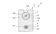
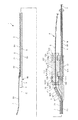
図1は、本発明の内視鏡の第1実施形態を示す図であって、図1(a)は、平面図、図1(b)は、側面図である。図2は、図1に示す内視鏡の断面図、図3は、図2中のA−A線での操作部を示す断面図、図4は、図2中のB−B線での操作部を示す断面図、図5〜図7は、図1に示す内視鏡の断面図である。
Hereinafter, an endoscope of the present invention will be described in detail based on a preferred embodiment shown in the accompanying drawings.
<First Embodiment>
FIG. 1 is a diagram showing a first embodiment of an endoscope of the present invention, in which FIG. 1 (a) is a plan view and FIG. 1 (b) is a side view. 2 is a cross-sectional view of the endoscope shown in FIG. 1, FIG. 3 is a cross-sectional view showing an operation unit taken along line AA in FIG. 2, and FIG. 4 is a cross-sectional view taken along line BB in FIG. FIG. 5 to FIG. 7 are sectional views of the endoscope shown in FIG. 1.
なお、以下では、図1、図2、図5〜図10、図15中の左側を「先端」、右側を「基端」、上側を「上」、下側を「下」として説明を行う。 In the following description, the left side in FIGS. 1, 2, 5 to 10, and 15 is referred to as “tip”, the right side is “base”, the upper side is “upper”, and the lower side is “lower”. .
図1〜図4に示すように、内視鏡1は、生体の管腔内に挿入される長尺状の内視鏡本体2と、内視鏡本体2の先端に設置され、観察部位を撮像する撮像素子3と、撮像素子3の先端に設置され、複数または単数のレンズ等で構成された撮像光学系4と、観察部位を照らす光を導光し、その光を先端部から出射するライトガイド5とを備えている。
As shown in FIGS. 1 to 4, the endoscope 1 is installed at a long endoscope
本発明の内視鏡の用途は、特に限定されないが、例えば、子宮内を観察する子宮鏡、膣内を観察する膣鏡、経膣的に使用される腹腔鏡として用いることが好ましい。本実施形態では、代表的に、内視鏡1を腹腔鏡、すなわち、経膣的腹腔鏡とする場合について説明する。 Although the use of the endoscope of the present invention is not particularly limited, for example, it is preferably used as a hysteroscope for observing the inside of the uterus, a colposcope for observing the inside of the vagina, and a laparoscope used transvaginally. In the present embodiment, a case where the endoscope 1 is a laparoscope, that is, a transvaginal laparoscope will be described as a representative example.
以下、内視鏡1の各構成要素について順次説明する。
撮像素子3としては、例えば、CCDイメージセンサ、CMOSイメージセンサ等の固体撮像素子を用いることができる。
Hereinafter, each component of the endoscope 1 will be sequentially described.
As the
この撮像素子3と撮像光学系4とは、図示の構成では、ケーシング内に収納され、一体化された1つのパッケージになっている。本明細書では、そのケーシングを含めて、撮像素子3の部分を撮像素子3と言い、撮像光学系4の部分を撮像光学系4と言う。これら撮像素子3および撮像光学系4により、撮像部30が構成される。なお、撮像素子3と撮像光学系4とが別体として設けられていてもよいことは言うまでもない。
In the illustrated configuration, the
また、撮像素子3および撮像光学系4の内視鏡本体2の軸方向から見たときの外形形状は、それぞれ、特に限定されないが、図示の構成では、円形をなしている。また、撮像素子3の外径と撮像光学系4の外径とは、等しい。
In addition, the outer shapes of the
また、内視鏡本体2のその軸方向から見たときの外形形状は、特に限定されないが、図示の構成では、円形をなしている。この内視鏡本体2は、直線状をなし、その全長に亘って、可撓性、すなわち柔軟性のある部材で構成されている。内視鏡本体2が直線状をなすことにより、内視鏡本体2で生体を容易に貫通することができる。内視鏡本体2の構成材料としては、特に限定されないが、例えば、各種の樹脂材料を用いることができる。
Further, the outer shape of the endoscope
なお、内視鏡本体2の基端部が硬質部材で構成され、基端部よりも先端側の部位が、可撓性を有していてもよく、また、内視鏡本体2の先端部が可撓性を有し、先端部よりも基端側の部位が、硬質部材で構成されていてもよい。また、内視鏡本体2は、その全長に亘って硬質部材で構成されていてもよい。
Note that the proximal end portion of the
内視鏡本体2には、ライトガイド用ルーメン21が形成されている。ライトガイド用ルーメン21は、内視鏡本体2の基端から先端部まで形成されている。すなわち、ライトガイド用ルーメン21の先端部は、内視鏡本体2の先端部に位置し、基端は、内視鏡本体2の基端に開口している。また、ライトガイド用ルーメン21は、図示の構成では、内視鏡本体2の中心軸Oから偏心している。
A
また、内視鏡本体2の軸方向から見たとき、内視鏡本体2の少なくとも先端部は、撮像素子3より外側に突出していない。図示の構成では、内視鏡本体2の外径は、その全長に亘って一定であり、内視鏡本体2の軸方向から見たとき、内視鏡本体2は、その全長に亘って撮像素子3より外側に突出していない。すなわち、内視鏡本体2の外径と撮像素子3の外径とは等しく、撮像素子3の外周面と内視鏡本体2の外周面とが段差のない連続面を形成している。また、内視鏡本体2の軸方向から見たとき、ライトガイド用ルーメン21は、撮像素子3よりも内側に位置している。
Further, when viewed from the axial direction of the
これにより、内視鏡本体2の外径を小さくすることができ、これによって、被検査者や患者への負担を軽減することができる。
Thereby, the outer diameter of the endoscope
この内視鏡本体2および撮像素子3の外径は、それぞれ、10mm以下であることが好ましく、0.3〜5.0mm程度であることがより好ましく、0.5〜2.0mm程度であることがさらに好ましい。
The outer diameters of the
また、内視鏡本体2には、ケーブル用ルーメン23が形成されている。ケーブル用ルーメン23は、内視鏡本体2の基端から先端まで形成されている。すなわち、ケーブル用ルーメン23の先端部は、内視鏡本体2の先端に開口し、基端は、内視鏡本体2の基端に開口している。また、ケーブル用ルーメン23は、内視鏡本体2の中心に配置されている。
In addition, a
撮像素子3の各配線を含むケーブル6は、ケーブル用ルーメン23を挿通し、そのケーブル6の基端部は、コネクタ72に接続されている。
The
コネクタ72は、図示しない光源や制御部等を有する制御・光源装置の対応するコネクタに着脱自在に接続され、その制御・光源装置と撮像素子3との間で、画像信号や制御信号等の各信号の送受信がなされる。
The
ライトガイド5は、ライトガイド用ルーメン21に内視鏡本体2の軸方向に移動可能で、ライトガイド5の中心軸を中心に回動可能に挿入されている。
The
このライトガイド5は、光を導光することができるものであれば特に限定されないが、本実施形態では、効率良く導光する観点から、1本の光ファイバーまたは光ファイバーを複数本束ねてなる光ファイバー束で構成されている。なお、光ファイバー束の各光ファイバーは、互いに固定され、一体化されている。光ファイバーの構成材料としては、例えば、各種の樹脂材料やガラスが挙げられるが、樹脂材料が好ましい。また、ファイバーを構成する樹脂材料としては、例えば、ポリメチルメタクリレート、ポリスチレン、スチレンアクリロニトリル、ポリカーボネートおよびポリクロロスチレン等が挙げられる。
The
また、ライトガイド5の先端部は、外力が付与されていない自然状態で所定の形状に湾曲または屈曲している。したがって、ライトガイド5の先端部は、後述する側孔22から外部に突出すると、その復元力により、元の湾曲または屈曲形状に戻る。
Further, the tip portion of the
また、ライトガイド5の先端の角部は、丸みを帯びている。これにより、安全性が向上する。
なお、ライトガイド5の先端には、図示しない投光レンズが設けられていてもよい。
Moreover, the corner | angular part of the front-end | tip of the
A light projection lens (not shown) may be provided at the tip of the
また、ライトガイド5の先端部には、超音波またはX線で検出し得る図示しないマーカー、すなわち超音波マーカーまたはX線マーカーが設けられていることが好ましい。これにより、超音波マーカーを設けた場合には、例えば、超音波プローブを用い、得られた画像を見て、ライトガイド5の先端部の位置を確認しつつ操作を行うことができる。また、X線マーカーを設けた場合には、X線透視下でライトガイド5の先端部の位置を確認しつつ操作を行うことができる。
Moreover, it is preferable that a marker (not shown) that can be detected by ultrasonic waves or X-rays, that is, an ultrasonic marker or X-ray marker, is provided at the tip of the
超音波マーカーとしては、その構成材料として、例えば、ステンレス鋼、アルミニウムまたはアルミニウム合金、チタンまたはチタン合金のような金属材料を用い、表面に複数の微小な凹凸を設けたもの等が挙げられる。 The ultrasonic marker includes, for example, a metal material such as stainless steel, aluminum or an aluminum alloy, titanium or a titanium alloy, and a plurality of minute irregularities provided on the surface.
また、X線マーカーは、X線不透過材料、すなわちX線造影性を有する材料で構成されている。X線不透過材料としては、例えば、金、白金、タングステン等の貴金属、またはこれらを含む合金、例えば、白金−イリジウム合金等が挙げられる。 Further, the X-ray marker is made of an X-ray opaque material, that is, a material having X-ray contrast properties. Examples of the radiopaque material include noble metals such as gold, platinum, and tungsten, or alloys containing them, such as platinum-iridium alloys.
また、ライトガイド5は、その先端のみから光を出射する構成のものに限定されず、例えば、先端部の側面の少なくとも一部と、先端とから光を出射するよう構成されていてもよい。この場合、例えば、ライトガイド5の先端部の側面全体から光を出射するように構成したり、また、その側面のうちの非連続な複数の箇所から光を出射するように構成することができる。
Further, the
これにより、撮像素子3により撮像される観察部位全体を明るく照明することができ、視野を広くすることができる。また、ライトガイド5の先端部に目盛りを設けることにより、撮像素子3によりその目盛りを撮像することができ、これによって、診断部の位置が把握し易くなる。
Thereby, the whole observation part imaged with the image pick-up
ライトガイド5の先端部の側面から光を出射させる方法としては、例えば、ライトガイド5の先端部、すなわち、ライトガイド5を構成する光ファイバーの先端部の側面を研摩または研削したり、複数の微小な凹部を形成する。
As a method of emitting light from the side surface of the front end portion of the
また、ライトガイド5の外部に露出する部位の外周面には、その外周面を覆う補強層51が設けられている。具体的には、補強層51は、ライトガイド5の先端部のうちの光を出射する部位を除く部位および基端部に設けられている。これにより、ライトガイド5の外部に露出する部位を補強することができ、ライトガイド5のキンクを防止することができる。
In addition, a reinforcing
補強層51としては、例えば、ライトガイド5の外周面に線材を螺旋状に巻回してなるコイル、ライトガイド5の外周面を被覆する被覆層等が挙げられる。
Examples of the reinforcing
補強層51をコイルで構成する場合は、そのコイルの構成材料は特に限定されないが、金属材料が好ましい。コイルを構成する金属材料としては、例えば、ステンレス鋼、超弾性合金、コバルト系合金や、金、白金、タングステン等の貴金属、またはこれらを含む合金、例えば、白金−イリジウム合金等が挙げられる。そして、特に、コイルを貴金属のようなX線不透過材料で構成した場合には、そのコイルがX線マーカーとしても機能する。
When the reinforcing
また、補強層51を被覆層で構成する場合は、その被覆層の構成材料は特に限定されないが、樹脂材料が好ましい。被覆層を構成する樹脂材料としては、例えば、ポリウレタン等が挙げられる。なお、被覆層をポリウレタンで構成する場合は、ライトガイド5の摩擦が低減され、摺動性が向上する。
Further, when the reinforcing
ここで、前記内視鏡本体2の先端部には、内視鏡本体2の側面に開口し、ライトガイド用ルーメン21の先端部に連通する側孔(孔部)22が形成されている。この側孔22は、撮像素子3よりも基端側に形成されている。
Here, a side hole (hole) 22 is formed at the distal end portion of the endoscope
これにより、内視鏡1は、ライトガイド5を内視鏡本体2の軸方向に移動させることにより、ライトガイド5の先端部が側孔22から突出した状態(以下、「突出状態」とも言う)(図5〜図7参照)と、内視鏡本体2内に収納された状態(以下、「収納状態」とも言う)(図1および図2参照)とを採り得る。
As a result, the endoscope 1 moves the
内視鏡1を収納状態とすることにより、内視鏡本体2を円滑に移動させることができる。
By placing the endoscope 1 in the retracted state, the
そして、内視鏡1を突出状態とすることにより、ライトガイド5の先端部から出射する光によって観察部位を照明することができる。また、状況に応じて、ライトガイド5を移動させ、その先端部を最適な位置に配置することにより、状況に応じた最適な照明を行うことができる。
Then, by placing the endoscope 1 in a protruding state, the observation site can be illuminated with light emitted from the distal end portion of the
また、ライトガイド用ルーメン21の先端部は、中心軸Oに対して所定角度傾斜している。これにより、ライトガイド5の先端部を側孔22から円滑に突出させることができる。
The tip of the
このライトガイド用ルーメン21の先端部の中心軸Oに対する傾斜角度θは、1〜45°程度であることが好ましく、1〜30°程度であることがより好ましい。これにより、ライトガイド5の先端部を側孔22から突出させるときのライトガイド5の移動量を比較的少なくしつつ、そのライトガイド5の先端部を側孔22から円滑に突出させることができる。
The inclination angle θ of the distal end portion of the
また、内視鏡本体2のライトガイド用ルーメン21の内周面には、例えば、潤滑剤を塗布する等の摩擦低減処理を施してもよい。これにより、ライトガイド5を円滑に移動させることができる。
Further, the inner peripheral surface of the
また、ライトガイド5は、ライトガイド用ルーメン21を挿通し、そのライトガイド5の基端部は、コネクタ71に接続されている。
The
コネクタ71は、制御・光源装置の対応するコネクタに着脱自在に接続される。制御・光源装置の光源から発せられた光は、ライトガイド5の基端から入射し、ライトガイド5により導光され、ライトガイド5の先端から出射し、所定の部位が照明される。照明光としては、特に限定されず、例えば、白色光、レーザ光等の単色光等が挙げられる。
The
また、内視鏡本体2の基端部には、ライトガイド5を内視鏡本体2の軸方向に移動操作し、ライトガイド5をその軸回りに回動操作する操作手段として、操作部8が設置されている。
In addition, at the proximal end portion of the
操作部8は、本体部9と、本体部9に対して軸方向に移動可能に設置された移動部11とを有している。
The operation unit 8 includes a
本体部9は、筒状をなしている。すなわち、本体部9には、その軸方向に延在し、先端および基端にそれぞれ開放する貫通孔93が形成されている。
The
また、本体部9の先端部には、ストッパー91が設けられ、基端部には、ストッパー92が設けられている。
A
また、ストッパー91には、サイドポート911が設けられており、そのサイドポート911の貫通孔912は、ストッパー91の先端に開放している。
Further, the
このストッパー91の先端部には、内視鏡本体2の基端部が固定されており、貫通孔912は、ライトガイド用ルーメン21に連通し、貫通孔93は、ケーブル用ルーメン23に連通している。
The proximal end of the
ケーブル6は、貫通孔93を挿通し、ライトガイド5は、貫通孔912を挿通している。
The
この本体部9のストッパー91に後述する移動部11の基台12が当接することにより、その移動部11の先端方向への移動が阻止され、また、ストッパー92に基台12が当接することにより、その移動部11の基端方向への移動が阻止される。すなわち、移動部11は、その基台12がストッパー91に当接した位置と、ストッパー92に当接した位置との間を移動することができる。
When the
移動部11は、本体部9に対して内視鏡本体2の軸方向に移動可能に設置された基台12と、基台12に対して、ライトガイド5の中心軸を中心に回動可能で、かつ着脱自在に設置された回動操作部材13と、回動操作部材13の先端部に着脱自在に設置されたキャップ14とを有している。
The moving
基台12には、軸方向に延在し、先端および基端にそれぞれ開放する貫通孔121が形成されている。本体部9は、この貫通孔121を挿通している。また、基台12は、その先端部および基端部に、それぞれ、上方に向って突出した支持部122および123を有している。各支持部122および123には、それぞれ、溝124および125が形成されている。
The
回動操作部材13は、筒状をなしている。すなわち、回動操作部材13には、その軸方向に延在し、先端および基端にそれぞれ開放する貫通孔137が形成されている。また、回動操作部材13は、その先端側から基端側に向って順次配置された大径部131、縮径部132、大径部133、縮径部134および大径部135を有している。
The
この回動操作部材13の縮径部132および134は、それぞれ、基台12の溝124および125に挿入され、回動可能で、かつ着脱自在に支持されている。回動操作部材13が基台12に対して着脱自在であるので、回動操作部材13を基台12から取り外して操作することができ、操作性し易いという利点を有する。
The reduced
また、回動操作部材13の大径部133の外周面には、軸方向に延在する4つのリブ136が形成されている。各リブ136は、互いに平行に、等間隔で配置されている。回動操作部材13を手指で回動操作する際、各リブ136により、その手指が滑ることを防止することができる。したがって、各リブ136により、滑り止め手段が構成される。
In addition, four
また、キャップ14の前記貫通孔137に対応する位置には、貫通孔141が形成されている。そして、ライトガイド5は、各貫通孔141、137を挿通している。
A through
なお、貫通孔137内に、例えば、シリコーンゴム等で構成された図示しないパッキンを設置してもよい。これにより、ライトガイド5のキンクを防止することができる。
In the through
また、大径部131の基端部の外周面には、雄ネジ1311が形成されている。そして、大径部131の雄ネジ1311よりも先端側の部位の外周面は、その外径が先端方向に向って漸減するテーパ面1312を構成している。
A
一方、キャップ14の基端部の内周面には、大径部131の雄ネジ1311と螺合する雌ネジ142が形成されている。そして、キャップ14の雌ネジ142よりも先端側の部位の内周面は、その内径が先端方向に向って漸減するテーパ面143を構成している。
On the other hand, on the inner peripheral surface of the base end portion of the
キャップ14を所定方向に回転させると、キャップ14が基端方向に移動し、そのテーパ面143より大径部131が径方向に圧縮され、大径部131の貫通孔137の内径が減少し、大径部131によりライトガイド5が保持される。これにより、ライトガイド5は、移動部11と一体的に軸方向に変位する。すなわち、移動部11を軸方向に移動させると、その移動部11とともにライトガイド5は、軸方向に移動する。また、回動操作部材13を軸回りに回動させると、その回動操作部材13とともにライトガイド5は、軸回りに回動する。
When the
また、キャップ14を前記と逆方向に回転させると、キャップ14が先端方向に移動し、そのテーパ面143よる大径部131の径方向への圧縮が解除され、大径部131が元の形状に復元し、その貫通孔137の内径が増大し、大径部131によるライトガイド5の保持が解除される。これにより、回動操作部材13に対してライトガイド5を軸方向に移動させることが可能になる。これによって、移動部11の移動のみでは、ライトガイド5の側孔22からの突出長さが不十分の場合に、ライトガイド5を側孔22からさらに突出させることができる。
このように、ライトガイド5は、回動操作部材13に着脱自在に連結される。
Further, when the
Thus, the
以上説明した操作部8の移動部11を先端方向に移動させると、その移動部11とともにライトガイド5が先端方向に移動し、また、移動部11を基端方向に移動させると、その移動部11とともにライトガイド5が基端方向に移動する。
When the moving
また、図1および図2に示すように、その移動部11が、ストッパー92に当接している状態では、ライトガイド5の先端部は、ライトガイド用ルーメン21内、すなわち、内視鏡本体2内に収納されている。
As shown in FIGS. 1 and 2, when the moving
そして、図5に示すように、移動部11を先端方向に移動させると、ライトガイド5は先端方向に移動し、ライトガイド5の先端部は、側孔22から外部に突出する。
As shown in FIG. 5, when the moving
さらに移動部11を先端方向に移動させると、ライトガイド5はさらに先端方向に移動し、ライトガイド5の先端部は、側孔22からさらに外部に突出する。このライトガイド5の先端部の突出、すなわち、ライトガイド5の先端方向への移動は、図6に示すように、移動部11がストッパー91に当接するまで行うことができる。
When the moving
ここで、この内視鏡1では、ライトガイド5の先端が撮像光学系4の先端よりも先端側に位置し得るように構成されている。そして、移動部11を軸方向に移動させることにより、ライトガイド5が軸方向に移動し、ライトガイド5の先端部の軸方向の位置を変更することができる。
Here, the endoscope 1 is configured such that the distal end of the
また、前述したように、ライトガイド5の先端部が湾曲または屈曲しており、図7に示すように、回動操作部材13を軸回りに回動させることにより、ライトガイド5が軸回りに回動し、ライトガイド5の先端部の方向を変更することができる。
Further, as described above, the tip portion of the
これにより、例えば、ライトガイド5の先端部を観察部位に接近させる等、ライトガイド5の先端部を最適な位置に配置することができる。これによって、観察部位を確実に照明することができる。すなわち、撮像光学系4および撮像素子3の小型化やライトガイド5の細径化等により内視鏡本体2の細径化を図りつつ、観察部位を明るく照らすことができる。また、状況に応じた最適な照明を行うことができる。
Thereby, for example, the front end portion of the
また、ライトガイド5の先端部を所望の方向に移動させることができるので、そのライトガイド5をガイドワイヤとして用いることもできる。すなわち、まずは、ライトガイド5を先端方向に移動させ、次に、内視鏡本体2をライトガイド5に沿って先端方向に移動させ、これを繰り返すことにより、内視鏡本体2をライトガイド5に沿って所望の位置に移動させることができる。
Moreover, since the front-end | tip part of the
なお、ライトガイド5の先端の撮像光学系4の先端よりも先端側への突出長の最大値は、特に限定されないが、0〜200mm程度の範囲内に設定されることが好ましく、0〜100mm程度の範囲内に設定されることがより好ましい。これにより、観察部位を確実に照明することができる。
Note that the maximum value of the protrusion length of the
以上説明したように、この内視鏡1によれば、内視鏡本体2を細径化することができ、これにより、被検査者や患者への負担を軽減することができる。
As described above, according to the endoscope 1, the endoscope
また、状況に応じて、ライトガイド5を移動させ、その先端部を最適な位置に配置することにより、状況に応じた最適な照明を行うことができる。また、ライトガイド5をガイドワイヤとして用いることもできる。
Further, by moving the
なお、本発明では、移動操作手段に、ライトガイド5の側孔22からの突出長を規制する機能を設けてもよい。
In the present invention, the moving operation means may be provided with a function of regulating the protruding length of the
この構成例としては、操作部8の本体部9と基台12との一方に、内視鏡本体2の軸方向に沿って複数の凹凸を形成し、他方に、その凹凸の凹部に挿入される突起を形成する。これにより、移動部11は、本体部9に対し、内視鏡本体2の軸方向に位置決めされ、これによって、移動部11が不本意に移動してしまうことを防止することができる。また、移動部11を移動させる際は、突起が各凹凸の凸部を乗り越えながら移動部11が移動することにより、クリック感が得られる。
As an example of this configuration, a plurality of irregularities are formed on one of the
したがって、前記複数の凹凸および突起により、移動部11を内視鏡本体2の軸方向に位置決めする手段であるクリック機構、すなわち、ライトガイド5の側孔22からの突出長を規制する手段の主要部が構成される。
Therefore, the click mechanism which is a means for positioning the moving
また、本発明では、本体部9等には、ライトガイド5の側孔22からの突出長や撮像光学系4の先端からの突出長を示す目盛りが設けられていてもよい。これにより、ライトガイド5の側孔22からの突出長や撮像光学系4の先端からの突出長を容易かつ確実に把握することができる。
In the present invention, the
なお、本実施形態では、ライトガイド5の先端部は、外力が付与されていない自然状態で所定の形状に湾曲または屈曲しているが、これに限らず、例えば、直線状をなしていてもよい。
In the present embodiment, the distal end portion of the
また、ライトガイド5およびライトガイド用ルーメン21の数は、それぞれ、1つに限らず、2つ以上でもよい。
The number of
なお、内視鏡1がライトガイド5を2つ以上有し、内視鏡本体2がライトガイド用ルーメン21を2つ以上有する場合、ライトガイド5が2つ以上設けられている場合は、各ライトガイド5が一体的に移動するように構成されていてもよく、また、各ライトガイド5が別々に移動するように構成されていてもよい。また、各ライトガイド5が一体的に回動するように構成されていてもよく、また、各ライトガイド5が別々に回動するように構成されていてもよい。
When the endoscope 1 has two or more light guides 5 and the endoscope
また、内視鏡1がライトガイド5を2つ以上有し、内視鏡本体2がライトガイド用ルーメン21を2つ以上有する場合、各ライトガイド用ルーメン21は、内視鏡本体2の周方向に沿って等間隔に配置されていることが好ましい。なお、各ライトガイド用ルーメン21の配置は、等間隔でなくてもよいことは言うまでもない。
When the endoscope 1 has two or more light guides 5 and the endoscope
また、本発明では、内視鏡本体2に、例えば、穿刺、薬液等の液体の投与・吸引、バイオプシー、縫合、クリッピング等を行うための他のルーメンを設けてもよい。この場合、そのルーメンの先端は、内視鏡本体2の撮像素子3よりも基端側の側面に開口する。これにより、内視鏡本体2を細径化することができる。
In the present invention, the
また、ライトガイド用ルーメン21以外のルーメンのうちの所定のルーメンと、ライトガイド用ルーメン21とは、その先端部において合流していてもよい。
In addition, a predetermined lumen of the lumens other than the
<第2実施形態>
図8は、本発明の内視鏡の第2実施形態における先端部を示す断面図である。
Second Embodiment
FIG. 8 is a cross-sectional view showing a distal end portion in the second embodiment of the endoscope of the present invention.
以下、第2実施形態について、前述した第1実施形態との相違点を中心に説明し、同様の事項については、その説明を省略する。 Hereinafter, the second embodiment will be described with a focus on the differences from the first embodiment described above, and the description of the same matters will be omitted.
図8に示す第2実施形態の内視鏡1では、撮像素子3および撮像光学系4は、内視鏡本体2の先端部に設置され、また、側孔22に代えて、孔部26が内視鏡本体2の先端面に形成されている。孔部26は、ライトガイド用ルーメン21の先端部に連通しており、この孔部26からライトガイド5の先端部が突出する。
In the endoscope 1 of the second embodiment shown in FIG. 8, the
また、撮像素子3および撮像光学系4は、内視鏡本体2の軸方向から見たとき、内視鏡本体2の中心から偏心した位置に配置されている。そして、孔部26は、内視鏡本体2の軸方向から見たとき、撮像素子3および撮像光学系4の偏っている側と反対側に配置されている。これにより、内視鏡本体2の軸方向から見たとき、撮像素子3および撮像光学系4を内視鏡本体2の中心から偏心させない場合に比べて、内視鏡本体2の径を小さくすることができる。
Further, the
<第3実施形態>
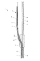
図9は、本発明の内視鏡の第3実施形態における先端部を示す平面図、図10は、図9に示す内視鏡の接続チューブの基端部を示す斜視図、図11は、図9中のC−C線での内視鏡本体を示す断面図、図12は、図9中のD−D線での内視鏡本体を示す断面図、図13は、図9中のE−E線での内視鏡本体を示す断面図、図14は、図9中のE−E線での内視鏡本体、接続チューブ、ライトガイドおよび処置用チューブを示す断面図、図15は、図9に示す内視鏡の基端部を示す断面図である。
<Third Embodiment>
FIG. 9 is a plan view showing a distal end portion in the third embodiment of the endoscope of the present invention, FIG. 10 is a perspective view showing a proximal end portion of a connection tube of the endoscope shown in FIG. 9, and FIG. 9 is a cross-sectional view showing the endoscope body taken along line CC in FIG. 9, FIG. 12 is a cross-sectional view showing the endoscope body taken along line DD in FIG. 9, and FIG. FIG. 14 is a cross-sectional view showing the endoscope main body taken along line EE, FIG. 14 is a cross-sectional view showing the endoscope main body, connection tube, light guide, and treatment tube taken along line EE in FIG. FIG. 10 is a cross-sectional view showing a proximal end portion of the endoscope shown in FIG. 9.
以下、第3実施形態について、前述した第1実施形態との相違点を中心に説明し、同様の事項については、その説明を省略する。 Hereinafter, the third embodiment will be described with a focus on differences from the first embodiment described above, and descriptions of the same matters will be omitted.
図9〜図15に示す第3実施形態の内視鏡1は、さらに、接続チューブ15を有し、内視鏡本体2は、さらに、ライトガイド用ルーメン21以外の他のルーメンとしてチューブ用ルーメン(処置用ルーメン)27を有している。
The endoscope 1 of the third embodiment shown in FIGS. 9 to 15 further includes a
チューブ用ルーメン27は、ライトガイド用ルーメン21と同様に形成され、そのライトガイド用ルーメン21に対して並設されている。すなわち、チューブ用ルーメン27の先端部は、内視鏡本体2の先端部に位置し、基端は、内視鏡本体2の基端に開口している。また、チューブ用ルーメン27の先端部は、側孔22に連通している。また、チューブ用ルーメン27は、内視鏡本体2の中心軸Oから偏心している。また、チューブ用ルーメン27とライトガイド用ルーメン21とは、その側方において連通している。
The
このチューブ用ルーメン27およびライトガイド用ルーメン21には、接続チューブ15が、内視鏡本体2の軸方向に移動可能に挿入されている。接続チューブ15の基端部は、操作部8のストッパー91のサイドポート911から突出しており、接続チューブ15の基端部を把持してその接続チューブ15を移動操作することができるようになっている。
The connecting
また、内視鏡1は、接続チューブ15を内視鏡本体2の軸方向に移動させることにより、接続チューブ15の先端部が側孔22から突出した状態と、内視鏡本体2内に収納された状態とを採り得るようになっている。そして、接続チューブ15の先端は、撮像光学系4の先端よりも先端側に位置し得るように構成されている。
Further, the endoscope 1 is housed in the endoscope
また、接続チューブ15は、ライトガイド用ルーメン21に対応した形状のライトガイド用ルーメン(第1の管腔)151と、チューブ用ルーメン27に対応した形状のチューブ用ルーメン(第2の管腔)152とを有している。また、ライトガイド用ルーメン151と、チューブ用ルーメン152とは、その側方において連通している。
The
そして、この接続チューブ15のライトガイド用ルーメン151には、ライトガイド5が、内視鏡本体2の軸方向に移動可能で、ライトガイド5の中心軸を中心に回動可能に挿入されている。
In the
また、チューブ用ルーメン152には、処置用チューブ16が、内視鏡本体2の軸方向に移動可能に挿入されている。
The
なお、処置用チューブ16は、接続チューブ15に対して内視鏡本体2の軸方向に移動し得ないようになっていてもよい。この具体例としては、処置用チューブ16に対して接続チューブ15を、例えば、接着剤により接着する方法や、融着する方法等が挙げられる。また、ライトガイド用ルーメン151と、チューブ用ルーメン152とは、その側方において連通していなくてもよい。
The
この内視鏡1では、まず、ライトガイド5から出射した光により目的部位を照らしつつ、接続チューブ15の先端部を目的部位の近傍に配置する。そして、処置用チューブ16を先端方向に移動させ、その処置用チューブ16の先端部を目的部位にさらに接近させる。この際、接続チューブ15においてライトガイド用ルーメン151とチューブ用ルーメン152とが平行に形成されているので、確実に、ライトガイド5により目的部位を照らしつつ、各操作を行うことができる。
In this endoscope 1, first, the distal end portion of the
以上、本発明の内視鏡を、図示の実施形態に基づいて説明したが、本発明はこれに限定されるものではなく、各部の構成は、同様の機能を有する任意の構成のものに置換することができる。また、本発明に、他の任意の構成物が付加されていてもよい。 As mentioned above, although the endoscope of the present invention has been described based on the illustrated embodiment, the present invention is not limited to this, and the configuration of each part is replaced with an arbitrary configuration having the same function. can do. In addition, any other component may be added to the present invention.
また、本発明は、前記各実施形態のうちの、任意の2以上の構成を組み合わせたものであってもよい。 Further, the present invention may be a combination of any two or more configurations of the above embodiments.
1 内視鏡
2 内視鏡本体
21 ライトガイド用ルーメン
22 側孔
23 ケーブル用ルーメン
26 孔部
27 チューブ用ルーメン
3 撮像素子
30 撮像部
4 撮像光学系
5 ライトガイド
51 補強層
6 ケーブル
71、72 コネクタ
8 操作部
9 本体部
91 ストッパー
911 サイドポート
912 貫通孔
92 ストッパー
93 貫通孔
11 移動部
12 基台
121 貫通孔
122、123 支持部
124、125 溝
13 回動操作部材
131、133、135 大径部
1311 雄ネジ
1312 テーパ面
132、134 縮径部
136 リブ
137 貫通孔
14 キャップ
141 貫通孔
142 雌ネジ
143 テーパ面
15 接続チューブ
151 ライトガイド用ルーメン
152 チューブ用ルーメン
16 処置用チューブ
DESCRIPTION OF SYMBOLS 1
Claims (14)
前記内視鏡本体の先端部に設置され、観察部位を撮像する撮像部と、
前記ライトガイド用ルーメンに挿入され、観察部位を照らす光を導光し、該光を先端部から出射する少なくとも1つのライトガイドとを備え、
前記ライトガイドは、前記ライトガイド用ルーメンに前記内視鏡本体の軸方向に移動可能で、該ライトガイドの中心軸を中心に回動可能に挿入され、
前記内視鏡本体は、前記内視鏡本体の先端部に開口し、前記ライトガイド用ルーメンの先端部に連通する孔部を有し、
前記ライトガイドを前記内視鏡本体の軸方向に移動させることにより、前記ライトガイドの先端部が、前記孔部から突出し、前記撮像部よりも先端側に配置された状態と、前記内視鏡本体内に収納された状態とを採り得るよう構成されていることを特徴とする内視鏡。 An elongated endoscope body that has at least one light guide lumen and is inserted into the lumen of a living body;
An imaging unit installed at the distal end of the endoscope main body and imaging an observation site;
Including at least one light guide inserted into the light guide lumen, guiding light that illuminates an observation site, and emitting the light from a tip portion;
The light guide is inserted into the light guide lumen so as to be movable in the axial direction of the endoscope main body, and is rotatable about the central axis of the light guide.
The endoscope body has a hole that opens at a distal end portion of the endoscope body and communicates with a distal end portion of the light guide lumen;
By moving the light guide in the axial direction of the endoscope main body, the distal end portion of the light guide protrudes from the hole portion and is disposed closer to the distal end side than the imaging unit, and the endoscope An endoscope that is configured to be able to take a state of being housed in the body.
前記本体部に対して前記内視鏡本体の軸方向に移動可能に設置された基台と、前記ライトガイドが連結され、前記基台に対して前記ライトガイドの中心軸を中心に回動可能に設置された回動操作部材とを有する移動部とを備える請求項2に記載の内視鏡。 The operating means includes a main body part,
A base installed to be movable in the axial direction of the endoscope main body with respect to the main body and the light guide are connected, and the base can be rotated around the central axis of the light guide. The endoscope according to claim 2, further comprising a moving unit having a rotation operation member installed on the endoscope.
前記孔部は、前記内視鏡本体の前記撮像部よりも基端側の側面に形成されている請求項1ないし8のいずれかに記載の内視鏡。 The imaging unit is installed at the tip of the endoscope body,
The endoscope according to any one of claims 1 to 8, wherein the hole is formed on a side surface of the endoscope main body closer to the base end side than the imaging unit.
当該内視鏡は、前記ライトガイド用ルーメンおよび前記処置用ルーメンに、前記内視鏡本体の軸方向に移動可能に挿入され、第1の管腔および該第1の管腔に対して並設され第2の管腔を有する接続チューブを備え、
前記接続チューブを前記内視鏡本体の軸方向に移動させることにより、前記接続チューブの先端部が前記孔部から突出した状態と、前記内視鏡本体内に収納された状態とを採り得るよう構成されており、
前記ライトガイドは、前記第1の管腔に前記内視鏡本体の軸方向に移動可能で、該ライトガイドの中心軸を中心に回動可能に挿入されている請求項1ないし13のいずれかに記載の内視鏡。 The endoscope body has a treatment lumen that is arranged in parallel to the light guide lumen and communicates laterally with the light guide lumen;
The endoscope is inserted into the light guide lumen and the treatment lumen so as to be movable in the axial direction of the endoscope main body, and is arranged in parallel with the first lumen and the first lumen. A connecting tube having a second lumen,
By moving the connection tube in the axial direction of the endoscope main body, it is possible to adopt a state in which the distal end portion of the connection tube protrudes from the hole portion and a state in which the connection tube is accommodated in the endoscope main body. Configured,
The light guide is inserted into the first lumen so as to be movable in the axial direction of the endoscope main body and rotatable about the central axis of the light guide. The endoscope according to 1.
Priority Applications (2)
| Application Number | Priority Date | Filing Date | Title |
|---|---|---|---|
| JP2010293144A JP5756629B2 (en) | 2010-12-28 | 2010-12-28 | Endoscope |
| PCT/JP2011/076704 WO2012070504A1 (en) | 2010-11-24 | 2011-11-18 | Endoscope |
Applications Claiming Priority (1)
| Application Number | Priority Date | Filing Date | Title |
|---|---|---|---|
| JP2010293144A JP5756629B2 (en) | 2010-12-28 | 2010-12-28 | Endoscope |
Publications (3)
| Publication Number | Publication Date |
|---|---|
| JP2012139308A true JP2012139308A (en) | 2012-07-26 |
| JP2012139308A5 JP2012139308A5 (en) | 2014-02-13 |
| JP5756629B2 JP5756629B2 (en) | 2015-07-29 |
Family
ID=46676229
Family Applications (1)
| Application Number | Title | Priority Date | Filing Date |
|---|---|---|---|
| JP2010293144A Active JP5756629B2 (en) | 2010-11-24 | 2010-12-28 | Endoscope |
Country Status (1)
| Country | Link |
|---|---|
| JP (1) | JP5756629B2 (en) |
Cited By (8)
| Publication number | Priority date | Publication date | Assignee | Title |
|---|---|---|---|---|
| JP2015177984A (en) * | 2014-02-27 | 2015-10-08 | パナソニックIpマネジメント株式会社 | endoscope |
| JP5905980B1 (en) * | 2015-07-16 | 2016-04-20 | パナソニック株式会社 | Endoscope |
| JP5908155B1 (en) * | 2015-08-31 | 2016-04-26 | パナソニック株式会社 | Endoscope |
| JP2016116845A (en) * | 2015-11-02 | 2016-06-30 | パナソニックIpマネジメント株式会社 | Lens unit and endoscope |
| JP5951093B1 (en) * | 2015-08-31 | 2016-07-13 | パナソニック株式会社 | Endoscope |
| US9826890B2 (en) | 2014-02-27 | 2017-11-28 | Panasonic Intellectual Property Management Co., Ltd. | Endoscope and manufacturing method of endoscope |
| US9829698B2 (en) | 2015-08-31 | 2017-11-28 | Panasonic Corporation | Endoscope |
| JP2019047299A (en) * | 2017-08-31 | 2019-03-22 | 株式会社フジクラ | Imaging module and catheter with the same |
Citations (2)
| Publication number | Priority date | Publication date | Assignee | Title |
|---|---|---|---|---|
| JPS61126522A (en) * | 1984-11-26 | 1986-06-14 | Olympus Optical Co Ltd | Endoscope |
| JPH1024011A (en) * | 1996-07-11 | 1998-01-27 | Olympus Optical Co Ltd | Illuminating probe for endoscope |
-
2010
- 2010-12-28 JP JP2010293144A patent/JP5756629B2/en active Active
Patent Citations (2)
| Publication number | Priority date | Publication date | Assignee | Title |
|---|---|---|---|---|
| JPS61126522A (en) * | 1984-11-26 | 1986-06-14 | Olympus Optical Co Ltd | Endoscope |
| JPH1024011A (en) * | 1996-07-11 | 1998-01-27 | Olympus Optical Co Ltd | Illuminating probe for endoscope |
Cited By (13)
| Publication number | Priority date | Publication date | Assignee | Title |
|---|---|---|---|---|
| US9826890B2 (en) | 2014-02-27 | 2017-11-28 | Panasonic Intellectual Property Management Co., Ltd. | Endoscope and manufacturing method of endoscope |
| US10368727B2 (en) | 2014-02-27 | 2019-08-06 | Panasonic Intellectual Property Management Co., Ltd. | Endoscope and manufacturing method of endoscope |
| JP2015177984A (en) * | 2014-02-27 | 2015-10-08 | パナソニックIpマネジメント株式会社 | endoscope |
| JP5905980B1 (en) * | 2015-07-16 | 2016-04-20 | パナソニック株式会社 | Endoscope |
| US10359619B2 (en) | 2015-08-31 | 2019-07-23 | Panasonic Corporation | Endoscope |
| JP2017049378A (en) * | 2015-08-31 | 2017-03-09 | パナソニック株式会社 | Endoscope |
| JP5951093B1 (en) * | 2015-08-31 | 2016-07-13 | パナソニック株式会社 | Endoscope |
| US9829698B2 (en) | 2015-08-31 | 2017-11-28 | Panasonic Corporation | Endoscope |
| JP5908155B1 (en) * | 2015-08-31 | 2016-04-26 | パナソニック株式会社 | Endoscope |
| US10890753B2 (en) | 2015-08-31 | 2021-01-12 | Panasonic I-Pro Sensing Solutions Co., Ltd. | Endoscope |
| JP2016116845A (en) * | 2015-11-02 | 2016-06-30 | パナソニックIpマネジメント株式会社 | Lens unit and endoscope |
| JP2019047299A (en) * | 2017-08-31 | 2019-03-22 | 株式会社フジクラ | Imaging module and catheter with the same |
| US10462342B2 (en) | 2017-08-31 | 2019-10-29 | Fujikura Ltd. | Imaging module and imaging-module-attached catheter |
Also Published As
| Publication number | Publication date |
|---|---|
| JP5756629B2 (en) | 2015-07-29 |
Similar Documents
| Publication | Publication Date | Title |
|---|---|---|
| JP5756629B2 (en) | Endoscope | |
| JP6707097B2 (en) | Optical coupler for endoscope | |
| CN101933795B (en) | Combined type soft or hard endoscope | |
| US6447444B1 (en) | Video rectoscope | |
| CN102438534B (en) | Tissue displacement system and tissue removal device | |
| Levy et al. | Finger-guided surgical instrument | |
| US7862504B2 (en) | Insertion apparatus | |
| US20080051655A1 (en) | Ultrasonic endoscope, therapeutic system, treatment method using therapeutic system, endoscopic system, treatment method using ultrasonic endoscope, t-bar, and t-bar suturing device | |
| US20060189844A1 (en) | Endoscopic devide | |
| JPH11276422A (en) | Ultrasonic endoscope | |
| JP2018505703A (en) | Multi-directional swivel endoscope | |
| JP2014033716A (en) | Endoscope, endoscope apparatus, and endoscope system | |
| US20160367311A1 (en) | Instrumentation with Embedded Imaging Systems | |
| WO2012070504A1 (en) | Endoscope | |
| JP2008188332A (en) | Endoscope attachment and endoscope | |
| JP2013240409A (en) | Endoscope, endoscope apparatus, and endoscope system | |
| US20200297311A1 (en) | Dual lumen catheter | |
| JP2014012043A (en) | Pipe endoscope | |
| JP2627285B2 (en) | Hysteroscope for flexible tissue sampling | |
| JP2012110468A (en) | Endoscope | |
| JP7428734B2 (en) | Endoscopic imaging device, endoscope | |
| CN215502926U (en) | Bent pipe electronic hysteroscope | |
| EP3117756A1 (en) | Endoscope and endoscope system | |
| JP2012110469A (en) | Medical instrument | |
| Banerjee et al. | OmniFlex: omnidirectional flexible hand-held endoscopic manipulator with spheroidal joint |
Legal Events
| Date | Code | Title | Description |
|---|---|---|---|
| A521 | Request for written amendment filed |
Free format text: JAPANESE INTERMEDIATE CODE: A523 Effective date: 20131225 |
|
| A621 | Written request for application examination |
Free format text: JAPANESE INTERMEDIATE CODE: A621 Effective date: 20131225 |
|
| A131 | Notification of reasons for refusal |
Free format text: JAPANESE INTERMEDIATE CODE: A131 Effective date: 20150106 |
|
| A521 | Request for written amendment filed |
Free format text: JAPANESE INTERMEDIATE CODE: A523 Effective date: 20150305 |
|
| TRDD | Decision of grant or rejection written | ||
| A01 | Written decision to grant a patent or to grant a registration (utility model) |
Free format text: JAPANESE INTERMEDIATE CODE: A01 Effective date: 20150512 |
|
| A61 | First payment of annual fees (during grant procedure) |
Free format text: JAPANESE INTERMEDIATE CODE: A61 Effective date: 20150601 |
|
| R150 | Certificate of patent or registration of utility model |
Ref document number: 5756629 Country of ref document: JP Free format text: JAPANESE INTERMEDIATE CODE: R150 |
|
| R250 | Receipt of annual fees |
Free format text: JAPANESE INTERMEDIATE CODE: R250 |
|
| R250 | Receipt of annual fees |
Free format text: JAPANESE INTERMEDIATE CODE: R250 |
|
| R250 | Receipt of annual fees |
Free format text: JAPANESE INTERMEDIATE CODE: R250 |
|
| R250 | Receipt of annual fees |
Free format text: JAPANESE INTERMEDIATE CODE: R250 |
|
| R250 | Receipt of annual fees |
Free format text: JAPANESE INTERMEDIATE CODE: R250 |
|
| R250 | Receipt of annual fees |
Free format text: JAPANESE INTERMEDIATE CODE: R250 |