JP2012138457A - Assembly structure for shield pipe, shield cable structure, and method for fixing shield cable - Google Patents
Assembly structure for shield pipe, shield cable structure, and method for fixing shield cable Download PDFInfo
- Publication number
- JP2012138457A JP2012138457A JP2010289412A JP2010289412A JP2012138457A JP 2012138457 A JP2012138457 A JP 2012138457A JP 2010289412 A JP2010289412 A JP 2010289412A JP 2010289412 A JP2010289412 A JP 2010289412A JP 2012138457 A JP2012138457 A JP 2012138457A
- Authority
- JP
- Japan
- Prior art keywords
- tube
- shield
- outer tube
- resin
- assembly structure
- Prior art date
- Legal status (The legal status is an assumption and is not a legal conclusion. Google has not performed a legal analysis and makes no representation as to the accuracy of the status listed.)
- Pending
Links
- 238000000034 method Methods 0.000 title claims description 8
- 239000011347 resin Substances 0.000 claims abstract description 45
- 229920005989 resin Polymers 0.000 claims abstract description 45
- 230000002093 peripheral effect Effects 0.000 claims description 12
- 238000007747 plating Methods 0.000 claims description 7
- 229910052751 metal Inorganic materials 0.000 abstract description 15
- 239000002184 metal Substances 0.000 abstract description 15
- 238000009434 installation Methods 0.000 abstract description 9
- 238000004040 coloring Methods 0.000 abstract description 5
- 239000003086 colorant Substances 0.000 abstract 1
- 230000001681 protective effect Effects 0.000 description 10
- 239000011295 pitch Substances 0.000 description 6
- 239000011248 coating agent Substances 0.000 description 4
- 238000000576 coating method Methods 0.000 description 4
- 238000005452 bending Methods 0.000 description 3
- 230000002411 adverse Effects 0.000 description 2
- 238000007772 electroless plating Methods 0.000 description 2
- 238000012423 maintenance Methods 0.000 description 2
- 238000012986 modification Methods 0.000 description 2
- 230000004048 modification Effects 0.000 description 2
- 229910000831 Steel Inorganic materials 0.000 description 1
- 229910052782 aluminium Inorganic materials 0.000 description 1
- XAGFODPZIPBFFR-UHFFFAOYSA-N aluminium Chemical compound [Al] XAGFODPZIPBFFR-UHFFFAOYSA-N 0.000 description 1
- 230000006866 deterioration Effects 0.000 description 1
- 238000010586 diagram Methods 0.000 description 1
- 239000000428 dust Substances 0.000 description 1
- 230000000694 effects Effects 0.000 description 1
- 238000009713 electroplating Methods 0.000 description 1
- 239000004744 fabric Substances 0.000 description 1
- 239000010959 steel Substances 0.000 description 1
- 239000004575 stone Substances 0.000 description 1
- KKEYFWRCBNTPAC-UHFFFAOYSA-L terephthalate(2-) Chemical compound [O-]C(=O)C1=CC=C(C([O-])=O)C=C1 KKEYFWRCBNTPAC-UHFFFAOYSA-L 0.000 description 1
Images


Abstract
Description
本発明は、識別性に優れ、取り扱い性に優れるシールド管の組立構造、シールドケーブル構造およびシールドケーブルの固定方法に関するものである。 The present invention relates to a shield tube assembly structure, a shield cable structure, and a shield cable fixing method that are excellent in distinguishability and handleability.
従来、例えば自動車等に用いられるケーブルの保護管としては、鋼管やアルミニウムパイプなどの金属管が用いられている。金属管は、通常、自動車の車体下部に設けられる。保護管が金属管であるため、外部からのノイズに対しては、保護管自体がシールド性を有し、ノイズの影響を受けにくい。しかし、金属管を所定の形状に加工するため、加工費がかさみ、電子機器等のレイアウトや配置の自由度が低い。また、金属製であるため重さの問題もある。したがって、シールド性を有する樹脂管が検討されている。 Conventionally, metal pipes such as steel pipes and aluminum pipes are used as protective pipes for cables used in automobiles, for example. The metal tube is usually provided at the lower part of the vehicle body. Since the protective tube is a metal tube, the protective tube itself has a shielding property against external noise, and is not easily affected by noise. However, since the metal tube is processed into a predetermined shape, the processing cost is high, and the degree of freedom in layout and arrangement of the electronic device or the like is low. Moreover, since it is metal, there also exists a problem of weight. Therefore, a resin pipe having shielding properties has been studied.
このような、シールド管としては、例えば、樹脂製のコルゲートチューブに無電解メッキ法を用いて金属層を形成することで、シールド性を有するコルゲートチューブを形成する方法がある(特許文献1、特許文献2)。
As such a shield tube, for example, there is a method of forming a corrugated tube having a shielding property by forming a metal layer on a resin corrugated tube using an electroless plating method (
しかし、特許文献1、特許文献2のコルゲートチューブは、そもそも電気自動車などに用いられる高電圧ケーブル用のシールド管については考慮されていない。通常、このような自動車等の高電圧ケーブルとして用いる場合には、他の一般的な保護管等と安全性の観点から区別する必要がある。例えば、このような高電圧線の保護管のみに着色を施す必要がある。しかしながら、ケーブル保護管の外部のメッキ層があるため、このような着色が困難である。例えば、従来の保護管の表面を単に塗装をしたのでは、塗装が剥離する恐れがある。
However, the corrugated tubes of
一方、自動車に用いられる高電圧配管は、自動車の下部に設置されるため、石等が衝突した際に、表面のメッキ層(シールド層)が損傷し、シールド性を劣化させる恐れがある。したがって、このようなシールド層を確実に保護する必要がある。 On the other hand, since the high-voltage piping used in the automobile is installed in the lower part of the automobile, the plating layer (shield layer) on the surface may be damaged when a stone or the like collides, and the shielding performance may be deteriorated. Therefore, it is necessary to reliably protect such a shield layer.
本発明は、このような問題に鑑みてなされたもので、他のケーブル等と確実に識別が可能であり、耐久性にも優れ、設置作業等の取り扱い性にも優れるシールド管の組立構造、シールドケーブル構造およびシールドケーブルの固定方法を提供することを目的とする。 The present invention has been made in view of such problems, and can be reliably identified with other cables, etc., has excellent durability, and is excellent in handling structure such as installation work. It is an object to provide a shielded cable structure and a shielded cable fixing method.
前述した目的を達成するため、第1の発明は、シールド管に外管が被せられたシールド管の組立構造であって、外面の少なくとも一部に波付形状を有する樹脂管体の外周に導電部材が被覆されてシールド層が形成されるシールド管と、前記シールド管の外周に被せられ、内面に波付形状を有する外管と、を具備し、前記外管は、着色された樹脂で構成され、少なくとも一部に波付形状を有する前記樹脂管体の波ピッチと前記外管の波ピッチとが異なるか、前記樹脂管体の凸部外面の幅が、前記外管の凹部内面の幅よりも大きいか、あるいは前記樹脂管体の凹部外面の幅が、前記外管の凸部内面の幅より小さいことで、前記外管の内面の波付形状が、前記樹脂管体の波付形状に嵌り込まないことを特徴とするシールド管の組立構造である。ここで、シールド管の外面に形成される波付け形状は、少なくとも一部に有していれば良いから、外面の一部に限らず、外管の大部分に有していても、全長に渡って有しても良い。前記外管は、外管の断面の一部に、軸方向に連続した割り部が設けられることが望ましい。 In order to achieve the above-described object, a first invention is an assembly structure of a shield tube in which an outer tube is covered with a shield tube, and an outer periphery of a resin tube body having a corrugated shape on at least a part of the outer surface is electrically conductive. A shield tube in which a member is coated to form a shield layer; and an outer tube having a corrugated shape on an inner surface thereof, the outer tube being formed of a colored resin. The wave pitch of the resin tube having a corrugated shape at least partially differs from the wave pitch of the outer tube, or the width of the outer surface of the convex portion of the resin tube is the width of the inner surface of the concave portion of the outer tube. Or the width of the concave outer surface of the resin tube is smaller than the width of the convex inner surface of the outer tube, so that the corrugated shape of the inner surface of the outer tube is the corrugated shape of the resin tube. It is the assembly structure of the shield pipe | tube characterized by not fitting in. Here, since the corrugated shape formed on the outer surface of the shield tube only needs to be at least partially, it is not limited to a part of the outer surface, and even if it is included in most of the outer tube, You may have it across. The outer tube is preferably provided with a split portion that is continuous in the axial direction at a part of a cross section of the outer tube.
前記外管は、軸方向に伸縮可能なため圧縮した状態で前記シールド管の外部に設けられてもよい。前記シールド層は、前記樹脂管体の外面に形成されたメッキ層であってもよい。前記シールド層は、前記樹脂管体が導電部材によって被覆されて形成されたものならば、例えば導電布などで形成してもよい。 The outer tube may be provided outside the shield tube in a compressed state because it can expand and contract in the axial direction. The shield layer may be a plated layer formed on the outer surface of the resin tube. The shield layer may be formed of, for example, a conductive cloth as long as the resin tube is formed by being covered with a conductive member.
前記シールド管に前記外管を被せたときに、前記割り部の先端同士が相互に被さってもよい。前記外管は、前記割り部の対向位置の外周面又は内周面に切り込みが設けられてもよい。 When the outer tube is covered with the shield tube, the ends of the split portions may be covered with each other. The outer tube may be provided with cuts on an outer peripheral surface or an inner peripheral surface at a position facing the split portion.
第1の発明によれば、金属層であるシールド層を有する樹脂管体の外周に、外管が被せられるため、外管を構成する樹脂自体を着色することで、容易に外管を着色することができ、識別性に優れる。また、樹脂自体を着色するため、着色が剥がれる等の恐れがない。 According to the first invention, since the outer tube is put on the outer periphery of the resin tube body having the shield layer that is a metal layer, the outer tube is easily colored by coloring the resin itself constituting the outer tube. Can be distinguished. Further, since the resin itself is colored, there is no fear that the coloring is peeled off.
また、樹脂管体の少なくとも一部が波付形状であるため、可撓性に優れ、設置作業性に優れる。また、外管の内周面の凹凸形状と樹脂管体の外周面の凹凸形状とが互いに嵌り込むことがないため、外管が樹脂管体(シールド管)に対して容易に滑ることができる。したがって、管構造を変形させた際に、外管および樹脂管体の可撓性が悪化することがない。特に、樹脂管体および外管がいずれも波付管であり、樹脂管体の凸部外面の幅を、外管の凹部内面の幅よりも大きくすることで、外管を被せた際に、樹脂管体の凸部外面が外管の凹部内面にはまり込むことを確実に防止することができる。 Moreover, since at least a part of the resin tube has a corrugated shape, it is excellent in flexibility and installation workability. Moreover, since the uneven shape of the inner peripheral surface of the outer tube and the uneven shape of the outer peripheral surface of the resin tube do not fit each other, the outer tube can easily slide with respect to the resin tube (shield tube). . Therefore, when the tube structure is deformed, the flexibility of the outer tube and the resin tube does not deteriorate. In particular, the resin tube and the outer tube are both corrugated tubes, and when the outer tube is covered by making the width of the outer surface of the convex portion of the resin tube larger than the width of the inner surface of the concave portion of the outer tube, It is possible to reliably prevent the outer surface of the convex portion of the resin tube from getting stuck in the inner surface of the concave portion of the outer tube.
また、外管が軸方向に形成された割り部を有するため、取付性に優れる。また、内部のシールド管のみを設置後、外管を被せることも可能である。また、シールド層がメッキ層であれば、樹脂管体の可撓性を確実に確保することができるため、設置作業性にも優れる。 Moreover, since the outer tube has a split portion formed in the axial direction, it is excellent in mountability. It is also possible to cover the outer tube after installing only the inner shield tube. Further, if the shield layer is a plated layer, the flexibility of the resin tube can be ensured reliably, and the installation workability is excellent.
第2の発明は、第1の発明にかかるシールド管の組立構造を用い、前記シールド管に挿通される電線と、前記電線と接続され、前記シールド管の組立構造の両端部に設けられる端子部と、を具備することを特徴とするシールドケーブル構造である。 2nd invention uses the assembly structure of the shield pipe concerning 1st invention, The electric wire penetrated by the said shield pipe, and the terminal part provided in the both ends of the assembly structure of the said shield pipe connected with the said electric wire And a shielded cable structure characterized by comprising:
前記外管の内部において、前記外管と前記シールド管の外周部との間に被覆線を配置してもよい。前記外管または前記シールド管の少なくともいずれかは、断面が略矩形形状であってもよい。 Inside the outer tube, a covered wire may be disposed between the outer tube and the outer periphery of the shield tube. At least one of the outer tube and the shield tube may have a substantially rectangular cross section.
第2の発明によれば、高電圧ケーブルとして用いても、容易に他のケーブルと識別することができ、取り扱い性にも優れ、外管によって確実にシールド層が保護される。例えば、高圧ケーブルの場合は、通常黄色に着色されるが、黄色の着色が剥がれる等の恐れもない。 According to the second invention, even if it is used as a high voltage cable, it can be easily distinguished from other cables, it is excellent in handleability, and the shield layer is reliably protected by the outer tube. For example, in the case of a high voltage cable, it is usually colored yellow, but there is no fear that the yellow color will be peeled off.
第3の発明は、第2の発明にかかるシールドケーブル構造を用い、前記外管の外周に形成される波付形状の少なくとも谷部に固定部材を設けて、構造体に固定することを特徴とするシールドケーブルの固定方法である。なお、前記シールドケーブル構造の構造体への固定に際しては、例えば、シールドケーブル構造の直線部や曲がり部などの固定レイアウトに応じて、順次曲げを行った後、固定部材により、構造体に順次固定するのが望ましい。ここで、固定部材は単に構造体への固定機能だけでなく、曲げ部の形状維持機能を有する方が良い。 A third invention is characterized in that the shielded cable structure according to the second invention is used, and a fixing member is provided in at least a trough portion of the corrugated shape formed on the outer periphery of the outer tube, and is fixed to the structure. This is a method for fixing a shielded cable. When fixing the shielded cable structure to the structure, for example, after sequentially bending according to the fixed layout of the shield cable structure, such as a straight portion or a bent portion, the shield cable structure is sequentially fixed to the structure by a fixing member. It is desirable to do. Here, it is better that the fixing member has not only a function of fixing to the structure but also a function of maintaining the shape of the bent portion.
第3の発明によれば、バンドや紐部材などの固定部材を用い、当該固定部材をシールドケーブルの外周の少なくとも谷部に設置して構造体に固定することで、シールドケーブルが構造体に対してずれることがなく、確実にシールドケーブルを固定することができる。 According to the third invention, by using a fixing member such as a band or a string member, the fixing member is installed in at least a valley portion of the outer periphery of the shielded cable and fixed to the structure, whereby the shielded cable is attached to the structure. The shielded cable can be securely fixed without shifting.
本発明によれば、他のケーブル等と確実に識別が可能であり、耐久性にも優れ、設置作業等の取り扱い性にも優れるシールド管の組立構造、シールドケーブル構造およびシールドケーブルの固定方法を提供することができる。 According to the present invention, there are provided a shield tube assembly structure, a shield cable structure, and a shield cable fixing method that can be reliably distinguished from other cables, have excellent durability, and handleability such as installation work. Can be provided.
以下、本発明の実施の形態にかかるシールドケーブル1について説明する。図1は、シールドケーブル1を示す図である。シールドケーブル1は、主にシールド管3、外管5、端子7、電線9等から構成される。
Hereinafter, a shielded
シールド管3は、可撓性を有する樹脂製の波付管から構成される。シールド管の少なくとも外面には、金属層であるシールド層が形成される。シールド層としては、例えば金属メッキ(無電解メッキおよび電解メッキの二重構造)が樹脂管体の表面に設けられてもよく、金属テープや金属メッシュ等が樹脂管体の外周に少なくとも1層以上、巻き付けられて構成されてもよい。いずれにしてもシールド管3は、シールド層が形成された状態で、可撓性を有すればよい。
The
シールド管3内部には、電線9が挿通される。被覆線である電線9の両端部は、電気的に端子7と接続される。端子7は、例えば自動車等のバッテリーとモータ等にそれぞれ設けられる端子部と接続可能である。なお、端子形状は、接続対象に応じて適宜設定される。
An electric wire 9 is inserted into the
シールド管3の外周には外管5が被せられる。外管5は、可撓性を有する樹脂製の管体である。外管5は、あらかじめ着色された樹脂で形成される。例えば、黄色、オレンジ色や赤色など、他の樹脂管や金属管と識別可能な着色が施される。安全対策上、着色が義務付けられているところに用いるには好適である。
The
図2、図3は、シールド管3に外管5を被せる状態を示す図であり、図2は分解斜視図、図3は組み立て斜視図である。なお、図2、図3においては、電線等は図示を省略する。前述の通り、シールド管3は波付管である。外管5は、軸方向に割り部11を有する部材であり、閉じた状態(図3)では、波付管状になる。外管5は、割り部11が開いた状態で(図2)シールド管3の外周に被せられて、割り部11を閉じることで外管5によりシールド管3が被覆される。なお、図1〜図3においては、割り部11にわずかに隙間を設けた例を図示したが、完全に割り部11同士が密着するように被覆してもよい。
2 and 3 are views showing a state in which the
また、割り部11の対向する位置内周面には切り込み12が設けられる。なお、切り込み12は、外管5の内周面側の軸方向に沿って形成されてもよく、外管5の外周面側の軸方向に沿って形成されてもよい。すなわち、外管5の割り部11の対向面側に薄肉部を形成することで、外管5を容易に開くことができる。
In addition, a notch 12 is provided on the inner circumferential surface of the opposing portion of the split portion 11. The notch 12 may be formed along the axial direction on the inner peripheral surface side of the
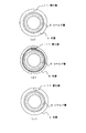
図4は、外管5をシールド管3の外周に被せた状態の軸方向から見た図である。図4(a)に示すように、外管5をシールド管3に被せた状態で、外管5は、割り部11の端面同士を単に接触させるだけでも良い。
FIG. 4 is a view of the
また、図4(b)に示すように、外管5をシールド管3に被せた状態で、外管5の割り部11の端部同士を、互いに重ね合わせるようにしてもよい。例えば、波形状の山部と谷部とを台形状に形成し、一方の端部の山部を他方の端部の山部に被せるように形成してもよい。
Moreover, as shown in FIG.4 (b), you may make it the edge parts of the split part 11 of the
また、図4(c)に示すように、外管5をシールド管3に被せた状態で、外管5の割り部11の端部同士を、互いに組み合わせるようにしてもよい。この場合には、割り部11の両端部には、凹凸形状や段差等を形成しておき、対向する端部同士の凹凸、段差同士を組み合わせてもよい。また、上記段差や凹凸を軸方向に形成し、割り部11同士の対向面を軸方向に形成された凹凸や段差等で組み合わせてもよい。
Moreover, as shown in FIG.4 (c), you may make it combine the ends of the split part 11 of the
なお、シールド管3および外管5は、自動車のシールドケーブルとして用いる場合には、ある程度の耐熱性を有することが望ましい。例えば、ポリブチルテレフタレート(PBT)樹脂製のものを用いることができる。ここで、シールド管3の外周に外管5を被覆した状態の構造をシールド管の組立構造と称する。
The
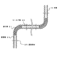
図5は、図3のA部の拡大断面図である。前述の通り、シールド管3は波付管13の外面にシールド層15が形成されて構成される。なお、図5においては、波付管13上に金属メッキ層であるシールド層15が形成された例を示す。
FIG. 5 is an enlarged cross-sectional view of a portion A in FIG. As described above, the
ここで、本発明では、外管とシールド管の嵌合構造を重視したため、外管の内面側で外管とシールド管の間から見た場合の外管の山部内面を凹部内面、谷部内面を凸部内面と表記した。また、同様に、シールド管の外面については、シールド管の山部外面は凸部外面、シールド管の谷部外面は凹部外面と表記した。そのため、外管とシールド管との間で、山部谷部ともに、凹凸関係が反対の表記となる。したがって、外管山部の内面を凹部内面、これと対向するシールド管の山部の外面を凸部外面と記載し、外管谷部の内面を凸部内面、これと対向するシールド管の谷部の外面を凹部外面と記載している。すなわち、シールド管3の山部外面を凸部外面3aとし、外管5の山部内面を凹部内面5bとすると、凸部外面3aの頂部の幅(軸方向に対する長さ)Bは、凹部内面5bの開口部における幅(軸方向に対する長さ)Cよりも大きい。したがって、外管5の凹部内面に嵌りこむべきシールド管3の凸部外面の幅が外管5の凹部内面より長いことから、シールド管の凸部外面が外管5の凹部内面に嵌り込むことがない。
Here, in the present invention, since the fitting structure between the outer tube and the shield tube is emphasized, the inner surface of the outer tube when viewed from between the outer tube and the shield tube on the inner surface side of the outer tube, The inner surface was described as the convex inner surface. Similarly, regarding the outer surface of the shield tube, the outer surface of the peak portion of the shield tube is expressed as the outer surface of the convex portion, and the outer surface of the valley portion of the shield tube is expressed as the outer surface of the concave portion. Therefore, the concave-convex relationship is reversed between the outer tube and the shield tube in both the mountain and valley portions. Therefore, the inner surface of the outer tube crest is described as the inner surface of the concave portion, the outer surface of the crest of the shield tube facing this is described as the outer surface of the convex portion, the inner surface of the outer tube valley is defined as the inner surface of the convex portion, and the valley of the shield tube facing this. The outer surface of the part is described as the outer surface of the recess. That is, when the outer surface of the crest of the
また、シールド管3の谷部外面を凹部外面3bとし、外管5の谷部内面を凸部内面5aとすると、外管5の凸部内面5aの頂部における幅(軸方向に対する長さ)Dは、シールド管3の凹部外面3bの開口部における部の幅(軸方向に対する長さ)Eよりも大きい。したがって、シールド管3の凹部外面に嵌り込むべき、外管5の凸部内面の幅がシールド管3の凹部外面より長いことから、外管の凸部内面がシールド管の凹部外面に嵌り込むことがない。
Further, when the outer surface of the valley portion of the
なお、シールド管3および外管5の波形状の波ピッチ(軸方向に対する断面における凸部または凹部のピッチ)は、同一であってもよく異なっていてもよい。また、シールド管3および外管5の波形状は、同一の形状であっても異なる形状であってもよい。なお、確実に凹凸の嵌り込みを防ぐためには、上述した凸部の頂部の幅が、凹部の開口部における幅よりも大きければよく、このような効果は、略矩形形状(長方形状、台形状)のように、頂部に辺端部を有するような波形状であることが望ましい。凸部の先端が円弧状や三角波等の場合には、凸部の先端が凹部の一部に嵌り込む恐れがあるためである。ここで、シールド管3および外管5の波形状の波ピッチが異なれば、少なくとも一部の外管5の凸部内面5aとシールド管3の凸部外面3aとが所定間隔で接触するため、外管5およびシールド管3の撓みを無視すれば、凸部内面5aが凹部外面3bに嵌り込むことがなく、また、同様に凸部外面3aが凹部内面5bに嵌り込むことがない。この場合には、例えば、波形状がサイン波であっても、互いの波ピッチが異なることにより、凹凸が互いに嵌り込むことがない。なお、外管5の内面にも金属メッキ等を施して、さらにシールド層を形成してもよい。
The wave pitches of the
以上、本実施の形態によれば、耐久性や識別性にも優れ、設置作業等の取り扱い性にも優れるシールドケーブルを得ることができる。特に、樹脂管体であるシールド管の外面にシールド層を形成した場合であっても、外周に外管を被せるため、シールド層が損傷を受けることを防止することができる。特に、自動車の下部に設けられた場合において、小石等がシールド層に直接ぶつかることがなく、シールド層を確実に保護することができる。したがって、シールド性能の信頼性が高い。 As described above, according to this embodiment, it is possible to obtain a shielded cable that is excellent in durability and distinguishability and excellent in handling properties such as installation work. In particular, even when the shield layer is formed on the outer surface of the shield tube that is a resin tube body, the outer tube is covered on the outer periphery, so that the shield layer can be prevented from being damaged. In particular, when it is provided at the lower part of an automobile, pebbles or the like do not directly hit the shield layer, and the shield layer can be reliably protected. Therefore, the reliability of the shielding performance is high.
また、高電圧用に用いる場合など、他のケーブルと識別する必要がある場合であっても、メッキ層上に塗装等を施すことなく、容易に視認することができる。この際、塗装とは異なり、経時劣化によって塗装がはがれ落ちることもない。 Moreover, even when it is necessary to distinguish from other cables, such as when used for high voltage, it can be easily visually recognized without coating or the like on the plating layer. At this time, unlike coating, the coating does not peel off due to deterioration with time.
また、シールド管3および外管5は、いずれも波付樹脂管体であり、可撓性を有する。このため、シールドケーブルを自動車下部等に設置する際においても設置経路に合わせてあらかじめ加工等を行う必要がなく、現場で容易に設置することができる。また、波付管が長さ方向に対しても多少の伸縮性を有するため、設置作業性に優れる。
Further, the
また、外管5の内面の凹凸とシールド管3の外面の凹凸とが互いに嵌りあうことがないため、外管5をシールド管3に被せた状態においても、シールドケーブルの可撓性に悪影響がない。すなわち、シールド管3の外面の凹凸と外管5の内面の凹凸とが嵌りあわずに摺動が可能であるため、曲げ部においても、外管5をシールド管3それぞれが曲げに容易に追従することができる。
Further, since the unevenness of the inner surface of the
なお、シールド管3と外管5との二重構造となるため、シールドケーブルに要求される強度を得るために、それぞれの管体の肉厚を薄くすることができる。すなわち、二重構造によって強度を発揮するため、個々の管体の強度を落とすことができる。このため、より可撓性を向上させることができる。
In addition, since it becomes the double structure of the
また、外管5には割り部11が形成されるため、外管5をシールド管3に被せることが容易である。また、外管5に割り部11が形成されるため、シールドケーブルが外部から衝撃を受けた際に、割り部11の変形(開閉等)によって衝撃を吸収することができる。特に、外部から、シールドケーブルの断面が偏平するような大きな力が加わった際に、割り部11においては大きな変形を起こすことが可能であるため、より大きな変形吸収能力を得ることができ、シールドケーブルの破損を防止することができる。
Moreover, since the split part 11 is formed in the
以上、添付図を参照しながら、本発明の実施の形態を説明したが、本発明の技術的範囲は、前述した実施の形態に左右されない。当業者であれば、特許請求の範囲に記載された技術的思想の範疇内において各種の変更例または修正例に想到し得ることは明らかであり、それらについても当然に本発明の技術的範囲に属するものと了解される。 As mentioned above, although embodiment of this invention was described referring an accompanying drawing, the technical scope of this invention is not influenced by embodiment mentioned above. It is obvious for those skilled in the art that various modifications or modifications can be conceived within the scope of the technical idea described in the claims, and these are naturally within the technical scope of the present invention. It is understood that it belongs.
例えば、外管5は波付形状を有しており、軸方向に伸縮が可能であれば、図6に示すように、外管5を軸方向に圧縮した状態で(図中矢印E方向)シールド管15に被せて、軸方向の端部を端子等で固定してもよい。このようにすると、外管5が、端子を常に押圧した状態で端子に取り付けられることになるので、外管の端部が端子に密着する。そのために、シールドケーブル内に埃や異物が入るのを防止することができる。
For example, if the
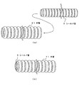
また、図7に示すように、シールド管3に代えてシールド管20を用いてもよい。シールド管20(樹脂管体)は、部分的に波付部21と直管部23とが形成される。波付部21は、シールドケーブルの敷設形態を考慮し、シールドケーブルを曲げて配置する部位に対応する位置にのみ形成される。すなわち、シールドケーブルは、波付部21で曲げられ、直線部に対応する部位には直管部23が位置するように構成される。
Further, as shown in FIG. 7, a shield tube 20 may be used instead of the
なお、この状態でも、波付部21の外面の凹凸と、外管5の内面の凹凸とが、互いに嵌り込まないような形状、ピッチ等で形成される。したがって、シールド管20と外管5とが互いに滑るため、可撓性に悪影響がない。
Even in this state, the irregularities on the outer surface of the corrugated portion 21 and the irregularities on the inner surface of the
このようにシールドケーブルを配置する場合には、敷設される構造体に対して、バンドや紐等の固定部材25を用いて固定される。固定部材25は、外管5の外周面の少なくとも谷部に嵌るように配置されて、構造体に固定される。したがって、固定部材25が外管5(シールドケーブル)に対してずれることがない。このため、シールドケーブルを確実に構造体に固定することができる。
When the shielded cable is arranged in this manner, it is fixed to the structure to be laid using a fixing member 25 such as a band or a string. The fixing member 25 is disposed so as to fit in at least a valley portion of the outer peripheral surface of the
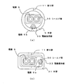
また、図8(a)に示すように、外管5の内部に、シールド管30に加え、被覆電線である電線9aを挿通してもよい。シールド管30は、略矩形(偏平形状)のシールド層を有する管体である。シールド管30には、高圧電線である電線9が挿通されている。電線9はシールド管30の内部に挿通されるため、電線9からのノイズは遮蔽される。したがって、シールド管30と外管5の隙間に挿通される電線9aは、電線9からのノイズの影響は受けない。なお、電線9は、低圧電線であり、低電圧の電力系や信号ケーブル等の微弱電流が流れる被覆電線である。
Moreover, as shown to Fig.8 (a), in addition to the shield pipe | tube 30, you may insert the electric wire 9a which is a covered electric wire inside the outer pipe |
また、図8(b)に示すように、外管31の形状も、シールド管30の形状に合わせて略矩形(偏平形状)としてもよい。すなわち、外管およびシールド管の少なくともいずれかを略矩形形状とすることで、効率良く内部に電線9aを配置することができる。また、矩形形状とすることで、自動車下の狭いスペースにおいても設置が容易であり、省スペース化が図れる。尚、外管31の内部の電線9aは1本のみを配置したが、複数本配置することも可能である。 Further, as shown in FIG. 8B, the shape of the outer tube 31 may be substantially rectangular (flat shape) in accordance with the shape of the shield tube 30. That is, the electric wire 9a can be efficiently arranged inside by making at least one of the outer tube and the shield tube into a substantially rectangular shape. Further, by adopting a rectangular shape, installation is easy even in a narrow space under the automobile, and space saving can be achieved. In addition, although only one electric wire 9a inside the outer tube 31 is arranged, a plurality of electric wires can be arranged.
このように電線9aを外管内部に配置することで、電線9aを別途保護管に挿通する必要がなく、シールド管と電線9aの保護を外管のみで行うことができる。したがって、ケーブル敷設スペースを小さくすることができる。 Thus, by arranging the electric wire 9a inside the outer tube, there is no need to insert the electric wire 9a separately into the protective tube, and the shield tube and the electric wire 9a can be protected only by the outer tube. Therefore, the cable laying space can be reduced.
また、図9(a)、図9(b)に示すように、外管の内周側に、電線9aを保持するための電線保持部33を形成してもよい。電線保持部33は、電線9aに対応した形状である。なお、電線保持部33は、外管の内周面のいずれの位置に形成してもよく、断面における電線およびシールド管のレイアウトに応じて適宜設定される。また、電線保持部33の形状は、電線9aに対応した形状であれば、いずれの形状でも良い。また、電線保持部33は、外管の軸方向に連続して形成されてもよく、所定の間隔をあけて設けられてもよい。 Further, as shown in FIGS. 9A and 9B, an electric wire holding portion 33 for holding the electric wire 9a may be formed on the inner peripheral side of the outer tube. The electric wire holding part 33 has a shape corresponding to the electric wire 9a. In addition, the electric wire holding | maintenance part 33 may be formed in any position of the internal peripheral surface of an outer tube | pipe, and is suitably set according to the layout of the electric wire and shield tube in a cross section. Moreover, the shape of the electric wire holding part 33 may be any shape as long as it corresponds to the electric wire 9a. Moreover, the electric wire holding | maintenance part 33 may be formed continuously in the axial direction of an outer tube | pipe, and may be provided at predetermined intervals.
また、図10(a)に示すように、割り部を有さない外管41を用いることもできる。外管41は、外管5とは割り部の有無のみで異なる。すなわち、外管41は、可撓性を有する樹脂製の管体であり、あらかじめ着色された樹脂で形成される。また、シールド管3の外面における凸部(外面山部)の頂部の幅は、外管41の凹部内面(外面山部の裏面に対応する)よりも大きい。したがって、シールド管3の凸部外面が外管41の凹部内面に嵌り込むことがない。なお、前述の通り、シールド管3および外管41の波形状の波ピッチは同一であっても異なっていてもよく、両者の波形状も同一の形状であっても異なる形状であってもよい。
Moreover, as shown to Fig.10 (a), the outer tube |
外管41を用いる場合には、シールド管3を外管41の端部から挿通すればよい。完全にシールド管3を外管41に挿通すれば、シールド管3の外周に外管41で被覆されたシールド管の組立構造を得ることができる(図10(b))。なお、外管41の断面形状は、図4に示す例(割り部および切れ込みを除く)と同様であってもよく、図8、図9に示すよう略矩形形状とし、被覆電線がシールド管と同時に挿通されていてもよい。
When the
1………シールドケーブル
3、20、30………シールド管
3a………凸部外面
3b………凹部外面
5、31、41………外管
5a………凸部内面
5b………凹部内面
7………端子
9………電線
11………割り部
13………波付管
15………シールド層
21………波付部
23………直管部
25………固定部材
33………電線保持部
DESCRIPTION OF
Claims (11)
外面の少なくとも一部に波付形状を有する樹脂管体の外周に導電部材が被覆されてシールド層が形成されるシールド管と、
前記シールド管の外周に被せられ、内面に波付形状を有する外管と、
を具備し、
前記外管は、着色された樹脂で構成され、
少なくとも一部に波付形状を有する前記樹脂管体の波ピッチと前記外管の波ピッチとが異なるか、前記樹脂管体の凸部外面の幅が、前記外管の凹部内面の幅よりも大きいか、あるいは前記樹脂管体の凹部外面の幅が、前記外管の凸部内面の幅より小さいことで、前記外管の内面の波付形状が、前記樹脂管体の波付形状に嵌り込まないことを特徴とするシールド管の組立構造。 A shield tube assembly structure in which a shield tube is covered with an outer tube,
A shield tube in which at least a part of the outer surface has a corrugated shape and the outer periphery of the resin tube is covered with a conductive member to form a shield layer;
An outer tube that is placed on the outer periphery of the shield tube and has a corrugated shape on the inner surface;
Comprising
The outer tube is made of a colored resin,
The wave pitch of the resin tube having a corrugated shape at least partially differs from the wave pitch of the outer tube, or the width of the outer surface of the convex portion of the resin tube is larger than the width of the inner surface of the concave portion of the outer tube. The corrugated shape of the inner surface of the outer tube fits into the corrugated shape of the resin tube because the outer surface of the concave portion of the resin tube is larger or smaller than the width of the inner surface of the convex portion of the outer tube. An assembly structure of a shield tube characterized by not being inserted.
前記シールド管に挿通される電線と、
前記電線と接続され、前記シールド管の組立構造の両端部に設けられる端子部と、
を具備することを特徴とするシールドケーブル構造。 Using the assembly structure of the shield tube according to any one of claims 1 to 7,
An electric wire inserted through the shield tube;
A terminal portion connected to the electric wire and provided at both ends of the assembly structure of the shield tube;
A shielded cable structure characterized by comprising:
Priority Applications (1)
| Application Number | Priority Date | Filing Date | Title |
|---|---|---|---|
| JP2010289412A JP2012138457A (en) | 2010-12-27 | 2010-12-27 | Assembly structure for shield pipe, shield cable structure, and method for fixing shield cable |
Applications Claiming Priority (1)
| Application Number | Priority Date | Filing Date | Title |
|---|---|---|---|
| JP2010289412A JP2012138457A (en) | 2010-12-27 | 2010-12-27 | Assembly structure for shield pipe, shield cable structure, and method for fixing shield cable |
Publications (1)
| Publication Number | Publication Date |
|---|---|
| JP2012138457A true JP2012138457A (en) | 2012-07-19 |
Family
ID=46675653
Family Applications (1)
| Application Number | Title | Priority Date | Filing Date |
|---|---|---|---|
| JP2010289412A Pending JP2012138457A (en) | 2010-12-27 | 2010-12-27 | Assembly structure for shield pipe, shield cable structure, and method for fixing shield cable |
Country Status (1)
| Country | Link |
|---|---|
| JP (1) | JP2012138457A (en) |
Cited By (9)
| Publication number | Priority date | Publication date | Assignee | Title |
|---|---|---|---|---|
| WO2014034665A1 (en) * | 2012-08-27 | 2014-03-06 | 古河As株式会社 | Electromagnetic shielding tube |
| CN104584351A (en) * | 2012-08-27 | 2015-04-29 | 矢崎总业株式会社 | Electric wire routing structure |
| WO2015099128A1 (en) * | 2013-12-27 | 2015-07-02 | 古河電気工業株式会社 | Piping structure, and corrugated pipe with ribs |
| JP2015143570A (en) * | 2013-12-27 | 2015-08-06 | 古河電気工業株式会社 | Piping structure and ribbed corrugated tube |
| JP2015186400A (en) * | 2014-03-26 | 2015-10-22 | 住友電装株式会社 | Corrugated tube and electric wire module |
| CN105531892A (en) * | 2013-10-11 | 2016-04-27 | 矢崎总业株式会社 | Harness bending regulation member and harness routing structure using same |
| JP2016149886A (en) * | 2015-02-13 | 2016-08-18 | 住友電装株式会社 | Shield structure of wire |
| JP2017157492A (en) * | 2016-03-04 | 2017-09-07 | 住友電装株式会社 | Wire harness |
| WO2017200029A1 (en) * | 2016-05-17 | 2017-11-23 | サンデン・オートモーティブコンポーネント株式会社 | Electromagnetic shield member, electromagnetic shield cable device provided with said member, air conditioning device for vehicle provided with said member, and method for manufacturing electromagnetic shield cable device |
Citations (11)
| Publication number | Priority date | Publication date | Assignee | Title |
|---|---|---|---|---|
| JPH09298382A (en) * | 1996-05-07 | 1997-11-18 | Yazaki Corp | Shield plating corrugate tube |
| JPH11275731A (en) * | 1998-03-20 | 1999-10-08 | Mitsubishi Shindoh Co Ltd | Electromagnetic wave shield |
| JP2000123644A (en) * | 1998-10-14 | 2000-04-28 | Audio Technica Corp | Cable |
| JP2000287331A (en) * | 1999-03-30 | 2000-10-13 | Yazaki Corp | Corrugated tube for protecting electric-wire coating |
| JP2000312089A (en) * | 1999-04-27 | 2000-11-07 | Sumitomo Wiring Syst Ltd | Electromagnetic wave shield structure for branch portion of wiring harness |
| JP2001035268A (en) * | 1999-07-23 | 2001-02-09 | Riken Vinyl Industry Co Ltd | Luminous cable and constructing method therefor |
| JP2007143264A (en) * | 2005-11-17 | 2007-06-07 | Yazaki Corp | Feeder system for slide structure |
| JP2007221085A (en) * | 2006-01-17 | 2007-08-30 | Inoac Corp | Electromagnetic shield tube and manufacturing method therefor |
| JP2008164001A (en) * | 2006-12-27 | 2008-07-17 | Nix Inc | Protective cover and its manufacturing method |
| JP2009123461A (en) * | 2007-11-14 | 2009-06-04 | Furukawa Electric Co Ltd:The | Shielding member |
| JP2009284725A (en) * | 2008-05-26 | 2009-12-03 | Kanto Auto Works Ltd | Corrugated clamp |
-
2010
- 2010-12-27 JP JP2010289412A patent/JP2012138457A/en active Pending
Patent Citations (11)
| Publication number | Priority date | Publication date | Assignee | Title |
|---|---|---|---|---|
| JPH09298382A (en) * | 1996-05-07 | 1997-11-18 | Yazaki Corp | Shield plating corrugate tube |
| JPH11275731A (en) * | 1998-03-20 | 1999-10-08 | Mitsubishi Shindoh Co Ltd | Electromagnetic wave shield |
| JP2000123644A (en) * | 1998-10-14 | 2000-04-28 | Audio Technica Corp | Cable |
| JP2000287331A (en) * | 1999-03-30 | 2000-10-13 | Yazaki Corp | Corrugated tube for protecting electric-wire coating |
| JP2000312089A (en) * | 1999-04-27 | 2000-11-07 | Sumitomo Wiring Syst Ltd | Electromagnetic wave shield structure for branch portion of wiring harness |
| JP2001035268A (en) * | 1999-07-23 | 2001-02-09 | Riken Vinyl Industry Co Ltd | Luminous cable and constructing method therefor |
| JP2007143264A (en) * | 2005-11-17 | 2007-06-07 | Yazaki Corp | Feeder system for slide structure |
| JP2007221085A (en) * | 2006-01-17 | 2007-08-30 | Inoac Corp | Electromagnetic shield tube and manufacturing method therefor |
| JP2008164001A (en) * | 2006-12-27 | 2008-07-17 | Nix Inc | Protective cover and its manufacturing method |
| JP2009123461A (en) * | 2007-11-14 | 2009-06-04 | Furukawa Electric Co Ltd:The | Shielding member |
| JP2009284725A (en) * | 2008-05-26 | 2009-12-03 | Kanto Auto Works Ltd | Corrugated clamp |
Cited By (14)
| Publication number | Priority date | Publication date | Assignee | Title |
|---|---|---|---|---|
| CN104584709B (en) * | 2012-08-27 | 2018-04-06 | 古河As株式会社 | Electromagnetic shield pipe |
| CN104584351A (en) * | 2012-08-27 | 2015-04-29 | 矢崎总业株式会社 | Electric wire routing structure |
| CN104584709A (en) * | 2012-08-27 | 2015-04-29 | 古河As株式会社 | Electromagnetic shielding tube |
| KR20150048130A (en) * | 2012-08-27 | 2015-05-06 | 후루카와 에이에스 가부시키가이샤 | Electromagnetic shielding tube |
| WO2014034665A1 (en) * | 2012-08-27 | 2014-03-06 | 古河As株式会社 | Electromagnetic shielding tube |
| KR102094565B1 (en) * | 2012-08-27 | 2020-03-27 | 후루카와 에이에스 가부시키가이샤 | Electromagnetic shielding tube |
| US9968017B2 (en) | 2012-08-27 | 2018-05-08 | Furukawa Automotive Systems Inc. | Electromagnetic shielding tube |
| CN105531892A (en) * | 2013-10-11 | 2016-04-27 | 矢崎总业株式会社 | Harness bending regulation member and harness routing structure using same |
| WO2015099128A1 (en) * | 2013-12-27 | 2015-07-02 | 古河電気工業株式会社 | Piping structure, and corrugated pipe with ribs |
| JP2015143570A (en) * | 2013-12-27 | 2015-08-06 | 古河電気工業株式会社 | Piping structure and ribbed corrugated tube |
| JP2015186400A (en) * | 2014-03-26 | 2015-10-22 | 住友電装株式会社 | Corrugated tube and electric wire module |
| JP2016149886A (en) * | 2015-02-13 | 2016-08-18 | 住友電装株式会社 | Shield structure of wire |
| JP2017157492A (en) * | 2016-03-04 | 2017-09-07 | 住友電装株式会社 | Wire harness |
| WO2017200029A1 (en) * | 2016-05-17 | 2017-11-23 | サンデン・オートモーティブコンポーネント株式会社 | Electromagnetic shield member, electromagnetic shield cable device provided with said member, air conditioning device for vehicle provided with said member, and method for manufacturing electromagnetic shield cable device |
Similar Documents
| Publication | Publication Date | Title |
|---|---|---|
| JP2012138457A (en) | Assembly structure for shield pipe, shield cable structure, and method for fixing shield cable | |
| US20090114304A1 (en) | Flexible pipe | |
| JP5480402B1 (en) | Electromagnetic shield tube, shielded cable structure, electromagnetic shield tube bending method, electromagnetic shield tube manufacturing method, and shielded cable connection structure | |
| JP5758087B2 (en) | Wire harness | |
| JP5867613B2 (en) | Wire harness | |
| JP5480177B2 (en) | Electromagnetic shield tube, shield cable structure, and method of bending electromagnetic shield tube | |
| WO2015093293A1 (en) | Protection material-attached electric cable | |
| JP2012064418A (en) | Waterproof construction of wiring harness | |
| JP2006521669A (en) | Electromagnetic shielding sleeve for the purpose of protecting cable bundles used for example in aviation technology | |
| AU2012244311B2 (en) | Cable for use in concentrated solar power installation | |
| JP2012178314A (en) | Shield conductor | |
| JP2012035803A (en) | Electrically conductive path for vehicle | |
| JP2018078761A (en) | Protection structure of wire joint and wire harness | |
| US9676350B2 (en) | Shielded pipe having fixed and bendable portions | |
| JP2011228371A (en) | Shield tape and cable | |
| EP2894741B1 (en) | Wire harness | |
| US10362718B2 (en) | Protective tube and harness | |
| JP2015089143A (en) | Exterior material for wire harness and wire harness | |
| JP2009135240A (en) | Shield structure of electric wire | |
| CN104538092A (en) | High-voltage cable with aluminum alloy conductor for electric vehicle | |
| JP5440446B2 (en) | Conductive path for vehicles | |
| CN212412653U (en) | Cable conduit made of mmp composite plastic steel material | |
| JP2007110819A (en) | Flat cable | |
| JP2012090500A (en) | Corrugated tube and wire harness | |
| CN204348361U (en) | A kind of high-tension cable used for electric vehicle with aluminium alloy conductor |
Legal Events
| Date | Code | Title | Description |
|---|---|---|---|
| A621 | Written request for application examination |
Free format text: JAPANESE INTERMEDIATE CODE: A621 Effective date: 20131108 |
|
| A977 | Report on retrieval |
Free format text: JAPANESE INTERMEDIATE CODE: A971007 Effective date: 20140418 |
|
| A131 | Notification of reasons for refusal |
Free format text: JAPANESE INTERMEDIATE CODE: A131 Effective date: 20140430 |
|
| A02 | Decision of refusal |
Free format text: JAPANESE INTERMEDIATE CODE: A02 Effective date: 20140902 |