JP2012134241A - Decoration object and decoration method of see-through type solar cell module - Google Patents
Decoration object and decoration method of see-through type solar cell module Download PDFInfo
- Publication number
- JP2012134241A JP2012134241A JP2010283544A JP2010283544A JP2012134241A JP 2012134241 A JP2012134241 A JP 2012134241A JP 2010283544 A JP2010283544 A JP 2010283544A JP 2010283544 A JP2010283544 A JP 2010283544A JP 2012134241 A JP2012134241 A JP 2012134241A
- Authority
- JP
- Japan
- Prior art keywords
- solar cell
- see
- cell module
- photoelectric conversion
- adhesive
- Prior art date
- Legal status (The legal status is an assumption and is not a legal conclusion. Google has not performed a legal analysis and makes no representation as to the accuracy of the status listed.)
- Granted
Links
Images


Classifications
-
- Y—GENERAL TAGGING OF NEW TECHNOLOGICAL DEVELOPMENTS; GENERAL TAGGING OF CROSS-SECTIONAL TECHNOLOGIES SPANNING OVER SEVERAL SECTIONS OF THE IPC; TECHNICAL SUBJECTS COVERED BY FORMER USPC CROSS-REFERENCE ART COLLECTIONS [XRACs] AND DIGESTS
- Y02—TECHNOLOGIES OR APPLICATIONS FOR MITIGATION OR ADAPTATION AGAINST CLIMATE CHANGE
- Y02E—REDUCTION OF GREENHOUSE GAS [GHG] EMISSIONS, RELATED TO ENERGY GENERATION, TRANSMISSION OR DISTRIBUTION
- Y02E10/00—Energy generation through renewable energy sources
- Y02E10/50—Photovoltaic [PV] energy
Abstract
Description
本発明は、光電変換機能を有するシースルー型太陽電池モジュールに関し、特に、発電と採光との機能を合わせ持つシースルー型太陽電池モジュールの加飾物および加飾方法に関する。 The present invention relates to a see-through solar cell module having a photoelectric conversion function, and more particularly to a decoration and a decoration method for a see-through solar cell module having both functions of power generation and daylighting.
近年、環境に対する意識の高まりやシステムの低価格化などにより、太陽エネルギを電気エネルギに変換する太陽光発電システムの普及が急激に拡大している。現在普及している太陽光発電システム用の太陽電池モジュール(光電変換装置)の主な形態は、以下の2種類に大別される。 In recent years, the spread of solar power generation systems that convert solar energy into electric energy has been rapidly expanding due to increased awareness of the environment and lower system prices. The main forms of solar cell modules (photoelectric conversion devices) for photovoltaic power generation systems that are currently in widespread use are roughly divided into the following two types.
1つは、単結晶シリコンや多結晶シリコンに代表されるような、バルク結晶の太陽電池セルを複数枚接続して構成した結晶系太陽電池モジュールの形態と、もう1つは、アモルファスシリコンや微結晶シリコンに代表されるような、基板上に光電変換層を薄膜として形成した薄膜太陽電池モジュールの形態である。 One is a crystalline solar cell module configured by connecting a plurality of bulk crystal solar cells, such as single crystal silicon or polycrystalline silicon, and the other is amorphous silicon or microcrystalline silicon. It is a form of a thin film solar cell module in which a photoelectric conversion layer is formed as a thin film on a substrate, as typified by crystalline silicon.
前者の結晶系太陽電池モジュールは、通常、単位面積当りの発電量を高めるために、結晶太陽電池セルを隙間無く並べて硝子で封止することでモジュール化する場合が多いが、セル間隔を広げて配置することで光透過性のあるシースルー型太陽電池モジュールとすることができる。 The former crystalline solar module is usually modularized by arranging crystalline solar cells without gaps and sealing them with glass in order to increase the amount of power generation per unit area. By arranging it, a see-through solar cell module having optical transparency can be obtained.
後者の薄膜太陽電池モジュールの代表的な構造としては、サブストレート型とスーパーストレート型との2種類があげられる。一般的に、太陽電池モジュールは、基板と光電変換層、透明電極、裏面電極層、グリッド電極が積層されている。 As a typical structure of the latter thin film solar cell module, there are two types, a substrate type and a superstrate type. In general, in a solar cell module, a substrate, a photoelectric conversion layer, a transparent electrode, a back electrode layer, and a grid electrode are laminated.
サブストレート型は基板に透光性のある基板を使用したり、不透光性基板に光を透過する開口部を形成したりすることで、光が薄膜太陽電地モジュールの裏側へ透過させ、シースルー型太陽電池モジュールとすることができる。 The substrate type uses a light-transmitting substrate as the substrate, or by forming an opening that transmits light in the light-impermeable substrate, so that the light is transmitted to the back side of the thin-film solar power module, A see-through solar cell module can be obtained.
また、スーパーストレート型は、光電変換層や裏面電極層の光透過率を上げることで、薄膜太陽電池モジュールに入射した光の一部を、裏面電極層を透過して薄膜太陽電池モジュールの裏側へ透過させ、シースルー型太陽電池モジュールとすることができる。 In addition, the super straight type increases the light transmittance of the photoelectric conversion layer and the back electrode layer, so that a part of the light incident on the thin film solar cell module is transmitted through the back electrode layer to the back side of the thin film solar cell module. The see-through solar cell module can be made to penetrate.
このようなシースルー型結晶系太陽電池モジュールおよびシースルー型薄膜太陽電池モジュールは、発電と採光との機能を合わせ持っている。
シースルー型薄膜太陽電池モジュールは、たとえば、建築物の窓や自動車の天井など、デザインの調和が要求される用途で有用である。特に、近年オフィスビルやサンルーフなど外壁の一部や全面が硝子で覆われた建築デザインが増えている。このような建築デザインに、シースルー型薄膜太陽電池モジュールを硝子窓に貼り付けたり、建材として硝子の代わりに使用したりすることで、建築物や自動車の窓や壁のスペースを発電に利用できると同時に、適度な遮光性のある窓として快適な居住環境をつくることができる。
Such see-through crystal solar cell modules and see-through thin film solar cell modules have both functions of power generation and daylighting.
The see-through thin film solar cell module is useful in applications that require harmony of design, such as building windows and automobile ceilings. In particular, in recent years, there has been an increase in architectural designs in which some or all of the outer walls of office buildings and sunroofs are covered with glass. In such architectural designs, see-through thin-film solar cell modules can be attached to glass windows or used as building materials in place of glass, so that spaces in buildings and automobiles can be used for power generation. At the same time, a comfortable living environment can be created as a window with moderate light shielding properties.
近年、太陽電池モジュールへのデザイン性付与として、光入射面側の外観に意図的に着色し、太陽電池モジュールに加飾を施す研究が進められている。
太陽電池モジュールの基板と光電変換層、透明電極、裏面電極層、グリッド電極などなどの素子の最表面に、水分等の浸入を阻止するために形成する透光性保護膜を形成する構成において、透光性に顔料や色素を添加して、太陽電池モジュールに加飾する方法が報告されている(たとえば、特許文献1参照)。
2. Description of the Related Art In recent years, research has been carried out to impart design to solar cell modules by intentionally coloring the appearance on the light incident surface side and decorating the solar cell modules.
In the configuration of forming a light-transmitting protective film formed to prevent intrusion of moisture etc. on the outermost surface of the element such as the substrate of the solar cell module and the photoelectric conversion layer, the transparent electrode, the back electrode layer, the grid electrode, There has been reported a method of decorating a solar cell module by adding a pigment or a pigment to the translucency (see, for example, Patent Document 1).
シースルー型太陽電池モジュールを建築物や自動車に設置する際、シースルー型太陽電池モジュールの光電変換機能を有する面を屋外に向け、光電変換機能を有しないシースルー型太陽電池モジュールの背面を屋内に向けて設置することになる。 When a see-through solar cell module is installed in a building or automobile, the surface with the photoelectric conversion function of the see-through solar cell module faces outside, and the back of the see-through solar cell module without the photoelectric conversion function faces indoors Will be installed.
前記の如くシースルー型太陽電池モジュールを設置して屋内や車内から外を見ると、積層構成における光電変換層や電極パターンが視認されることになる。また、透明電極膜などの薄膜の積層構成や膜厚の違いに起因した干渉色が視認され、そのままでは意匠性が低く、太陽電池モジュールと居住空間とのミスマッチが生じている。 As described above, when the see-through solar cell module is installed and viewed from the inside or the inside of the vehicle, the photoelectric conversion layer and the electrode pattern in the laminated structure are visually recognized. In addition, interference colors caused by differences in the laminated structure and film thickness of thin films such as transparent electrode films are visually recognized, and the design properties are low as they are, resulting in a mismatch between the solar cell module and the living space.
シースルー型太陽電池モジュールの背面に加飾を施す場合、光電変換素子や透明電極などを隠蔽して意匠性の付与と、光電変換素子の開口部には加飾を施さないことで透過した外光を室内や車内に採光し、明るさを確保することが求められるが、シースルー型太陽電池モジュールの開口部を避けて、絵柄などの加飾を精度良く施すことが難しく、意匠性と採光性とを両立することが難しいという問題がある。 When decorating the back of a see-through solar cell module, the photoelectric conversion element or transparent electrode is hidden to provide design and external light that is transmitted by not decorating the opening of the photoelectric conversion element However, it is difficult to accurately apply decorations such as patterns, avoiding the opening of the see-through solar cell module. There is a problem that it is difficult to achieve both.
本発明は、シースルー型太陽電池モジュールの光電変換機能を有しない背面に、意匠性と採光性とを兼ね備えた加飾を施すことで、シースルー型太陽電池型モジュールにおいて、採光性を低下させることなく、色や絵柄などの高い意匠性を付与することができるシースルー型太陽電池モジュールの加飾物および加飾方法を提供することを目的とする。 In the see-through solar cell module, the present invention provides a decoration that combines design and lighting on the back surface of the see-through solar cell module that does not have a photoelectric conversion function. An object of the present invention is to provide a decoration for a see-through solar cell module and a decoration method capable of imparting high design properties such as color and pattern.
本発明の請求項1に係わるシースルー型太陽電池モジュールの加飾物は、光電変換機能を有するシースルー型太陽電池モジュールの背面の全面に形成された粘着層に、光電変換素子上の粘着部および光電変換素子間の開口部上の非粘着部を形成し、前記光電変換素子上の前記粘着部にのみ箔状や粉体状の色材を選択的に貼り付けることで加飾を施したことを特徴とする。
The ornament of the see-through solar cell module according to
本発明の請求項2に係わるシースルー型太陽電池モジュールの加飾物は、請求項1において、前記粘着層は感光性を有し、所定の波長の光を照射することで粘着性が低下する材料からなることを特徴とする。
The see-through solar cell module decoration according to
本発明の請求項3に係わるシースルー型太陽電池モジュールの加飾物は、請求項項1または請求項2において、前記粘着層のシート抵抗値は1010Ω/□以上であることを特徴とする。
The ornament of the see-through solar cell module according to
本発明の請求項4に係わるシースルー型太陽電池モジュールの加飾物は、請求項項1乃至3のいずれかにおいて、前記箔状の色材は、顔料を分散した有機樹脂の薄膜や無機薄膜などからなる転写箔であり、離形層を有した剥離紙の上に前記転写箔が形成されていることを特徴とする。
The ornament of the see-through solar cell module according to
本発明の請求項5に係わるシースルー型太陽電池モジュールの加飾物は、請求項項1乃至4のいずれかにおいて、前記粉体状や箔状の色材の顔料は、有機顔料や無機顔料や金属フィラからなることを特徴とする。
The ornament of the see-through solar cell module according to claim 5 of the present invention is any one of
本発明の請求項6に係わるシースルー型太陽電池モジュールの加飾方法は、光電変換機能を有するシースルー型太陽電池モジュールの背面に感光性を有する粘着材からなる粘着層を形成する工程と、前記シースルー型太陽電池モジュールの表面から露光し、光電変換素子の形成されていない光電変換素子間の開口部に位置する粘着層の粘着性を低下させることにより、光電変換素子上の粘着部および前記開口部上の非粘着部を形成する工程と、前記粘着層の上に転写箔を形成した剥離紙をラミネートする工程と、前記剥離紙と転写箔を剥離し、前記粘着部のみに前記転写箔からなるパターンを形成する工程とを具備している。 The method for decorating a see-through solar cell module according to claim 6 of the present invention includes a step of forming an adhesive layer made of a photosensitive adhesive material on the back surface of a see-through solar cell module having a photoelectric conversion function, and the see-through method. The adhesive part on the photoelectric conversion element and the opening by reducing the adhesiveness of the adhesive layer that is exposed from the surface of the solar cell module and located in the opening between the photoelectric conversion elements where the photoelectric conversion element is not formed The step of forming the upper non-adhesive part, the step of laminating the release paper having the transfer foil formed on the adhesive layer, the release paper and the transfer foil are peeled off, and only the adhesive part is made of the transfer foil. Forming a pattern.
本発明の請求項7に係わるシースルー型太陽電池モジュールの加飾方法は、光電変換機能を有するシースルー型太陽電池モジュールの背面に感光性を有する粘着材からなる粘着層を形成する工程と、前記粘着層の上に転写箔を形成した剥離紙をラミネートする工程と、前記シースルー型太陽電池モジュールの表面から露光し、光電変換素子の形成されていない光電変換素子間の開口部に位置する粘着層の粘着性を低下させることにより、光電変換素子上の粘着部および前記開口部上の非粘着部を形成する工程と、前記剥離紙と転写箔を剥離し、前記粘着部のみに前記転写箔からなるパターンを形成する工程とを具備している。 The method for decorating a see-through solar cell module according to claim 7 of the present invention includes a step of forming an adhesive layer made of an adhesive material having photosensitivity on the back surface of a see-through solar cell module having a photoelectric conversion function; A step of laminating a release paper on which a transfer foil is formed on a layer, and an adhesive layer that is exposed from the surface of the see-through solar cell module and is located at an opening between photoelectric conversion elements in which no photoelectric conversion elements are formed The step of forming the adhesive part on the photoelectric conversion element and the non-adhesive part on the opening by reducing the adhesiveness, the release paper and the transfer foil are peeled off, and only the adhesive part is made of the transfer foil. Forming a pattern.
本発明の請求項8に係わるシースルー型太陽電池モジュールの加飾方法は、転写箔を形成した剥離紙に感光性を有する粘着材からなる粘着層を形成する工程と、光電変換機能を有するシースルー型太陽電池モジュールの背面に前記粘着層と転写箔を積層形成した剥離紙をラミネートする工程と、前記シースルー型太陽電池モジュールの表面から露光し、光電変換素子の形成されていない光電変換素子間の開口部に位置する粘着層の粘着性を低下させることにより、前記粘着層に粘着部および非粘着部を形成する工程と、前記剥離紙と転写箔を剥離し、前記粘着部のみに前記転写箔からなるパターンを形成する工程とを具備している。 The method for decorating a see-through solar cell module according to claim 8 of the present invention includes a step of forming an adhesive layer made of an adhesive material having photosensitivity on a release paper on which a transfer foil is formed, and a see-through type having a photoelectric conversion function. A step of laminating a release paper in which the adhesive layer and transfer foil are laminated on the back surface of the solar cell module, and an opening between the photoelectric conversion elements that are exposed from the surface of the see-through solar cell module and no photoelectric conversion elements are formed The adhesive layer and the non-adhesive part are formed on the adhesive layer by reducing the adhesiveness of the adhesive layer located in the part, and the release paper and the transfer foil are peeled off from the transfer foil only to the adhesive part. Forming a pattern.
本発明の請求項9に係わるシースルー型太陽電池モジュールの加飾方法は、光電変換機能を有するシースルー型太陽電池モジュールの背面に感光性を有する粘着材からなる粘着層を形成する工程と、前記シースルー型太陽電池モジュールの表面から露光し、光電変換素子の形成されていない光電変換素子間の開口部に位置する粘着層の粘着性を低下させることにより、光電変換素子上の粘着部および前記開口部上の非粘着部を形成する工程と、前記粘着層の全面に粉体状の色材を散布した後、余剰の粉体状の色材を除去し、前記粘着部のみに前記粉体状の色材からなるパターンを形成する工程とを具備している。 A method for decorating a see-through solar cell module according to claim 9 of the present invention includes a step of forming an adhesive layer made of an adhesive material having photosensitivity on the back surface of a see-through solar cell module having a photoelectric conversion function; The adhesive part on the photoelectric conversion element and the opening by reducing the adhesiveness of the adhesive layer that is exposed from the surface of the solar cell module and located in the opening between the photoelectric conversion elements where the photoelectric conversion element is not formed The step of forming the non-adhesive part above, and after spraying the powdery color material over the entire surface of the adhesive layer, the excess powdery color material is removed, and the powdery color material is applied only to the adhesive part. Forming a pattern made of a color material.
本発明の請求項1に係わるシースルー型太陽電池モジュールの加飾物によれば、シースルー型太陽電池モジュールの背面は光電変換素子が露出した状態になっている。
光電変換素子は真空成膜により銀など金属膜や透明導電膜などの金属酸化膜が積層されてパターンが形成されている。
背面全面に粘着層を形成し、光電変換素子上に粘着性を残して粘着部を形成し、光電変換素子の形成されていない開口部の粘着性を消失させて非粘着部を形成することで、選択的に光電変換素子上に箔状や粉体状の色材を定着することができる。
開口部は非粘着部となっているため、箔状や粉体状の色材が定着せず、シースルー型太陽電池モジュールの開口部を維持したまま、シースルー型太陽電気モジュールの背面の加飾物を得ることができる。
粘着層の上の色材層の定着を向上させるために、追加露光処理や熱処理により粘着材を硬化させることも可能である。また、本発明の色材の形成した上に透明樹脂層を形成し、加飾全面を被覆することも可能である。
According to the ornament of the see-through solar cell module according to
The photoelectric conversion element is formed by depositing a metal film such as silver or a metal oxide film such as a transparent conductive film by vacuum film formation.
By forming an adhesive layer on the entire back surface, leaving adhesiveness on the photoelectric conversion element, forming an adhesive part, and eliminating the adhesiveness of the opening where the photoelectric conversion element is not formed to form a non-adhesive part Alternatively, a foil-like or powder-like color material can be selectively fixed on the photoelectric conversion element.
Since the opening is a non-adhesive part, the decorative material on the back of the see-through solar electric module can be removed while maintaining the opening of the see-through solar cell module. Obtainable.
In order to improve fixing of the color material layer on the adhesive layer, the adhesive material can be cured by additional exposure treatment or heat treatment. It is also possible to form a transparent resin layer on the color material of the present invention and cover the entire decorative surface.
本発明の請求項2に係わるシースルー型太陽電池モジュールの加飾物によれば、粘着材に光反応により粘着性を消失する感光性材料を使用することで、粘着部と非粘着部とを形成することできる。
使用する波長は特に規定するものではなく、粘着材料の反応に寄与する輝線に合わせて紫外線域や可視光域のなど波長の線を使用することができる。
粘着材料としてはアクリル系樹脂、シリコン系樹脂、ウレタン系樹脂、エポキシ系樹脂、チオール系樹脂などが使用可能である。
粘着材料の輝線における光電変換素子の透過率を10%以下にすることで、シースルー型太陽電池モジュールの硝子面より露光することにより、光電変換素子を遮光マスクとして開口部の粘着層のみを選択的に感光させ、非粘着部を形成することができる。
また、粘着材に感光性と熱硬化性との両方の反応基を持たせることで、熱反応による密着性向上や粘着層の膜としての強度向上を図ることも可能である。
According to the ornament of the see-through solar cell module according to
The wavelength to be used is not particularly defined, and a line having a wavelength such as an ultraviolet ray region or a visible light region can be used in accordance with the bright line contributing to the reaction of the adhesive material.
As the adhesive material, acrylic resin, silicon resin, urethane resin, epoxy resin, thiol resin and the like can be used.
By making the transmittance of the photoelectric conversion element in the emission line of the
Moreover, it is also possible to improve the adhesiveness by heat reaction and the strength of the adhesive layer as a film by providing the adhesive material with both photosensitive and thermosetting reactive groups.
本発明の請求項3に係わるシースルー型太陽電池モジュールの加飾物によれば、シースルー型太陽電池モジュールの背面は光電変換素子のパターンが露出しており、粘着層を前面に形成するために、パターン間の絶縁性が必要である。電気的に絶縁性を確保するために、シート抵抗が1010Ω/□以上が望ましい。1010Ω/□未満では、加電圧により不要な部分に通電し、シースルー型太陽電池モジュールの発電効率が低下する原因となる。
また、光電変換素子の銀などの金属膜層は大気中の酸素や水分で変化しやすいため、電気的に絶縁性の高い皮膜で被覆することで変化を防止することができる。
また、粘着層の膜厚は、光電変換素子のパターンの凹凸を完全に被覆できる膜厚で形成すればよい。
According to the ornament of the see-through solar cell module according to
In addition, since the metal film layer such as silver of the photoelectric conversion element is easily changed by oxygen or moisture in the air, the change can be prevented by covering with a highly electrically insulating film.
Moreover, what is necessary is just to form the film thickness of the adhesion layer with the film thickness which can coat | cover the unevenness | corrugation of the pattern of a photoelectric conversion element completely.
本発明の請求項4に係わるシースルー型太陽電池モジュールの加飾物によれば、転写箔としては、顔料を分散した有機樹脂を塗工乾燥した薄膜や、金属や金属酸化物などの無機薄膜が使用可能である。
有機樹脂の薄膜としては、スリットコーター、マイクログラビアなどによる単色の薄膜や、オフセット印刷やグラビア印刷、スクリーン印刷などの印刷法による多色の柄が使用可能である。
また、無機薄膜と有機樹脂の薄膜を重ねて形成した転写箔も使用可能である。転写箔は、離形性を有する剥離紙上に形成されており、光電変換素子上の粘着部に剥離紙から転写箔のみが転写し、非粘着部は転写箔が剥離紙上に残ることで、光電変換素子上に選択的に加飾を施すことができる。
離形層としてはシリコンオイル、シリコンワニスで代表される離型剤、シリコンゴムの薄膜層を使用してもよい。また、同じ目的でフッ素系樹脂、フッ素系ゴムも利用されうるし、フッ素樹脂微粉末をシリコンゴムあるいは普通のゴムに混ぜて剥離性を出すなどの使い方をしてもよい。剥離紙としては、PETフィルム、アクリルフィルムなどが使用可能であり、特に規定するものではない。
According to the ornament of the see-through solar cell module according to
As the organic resin thin film, a single color thin film by a slit coater, a micro gravure or the like, or a multicolor pattern by a printing method such as offset printing, gravure printing or screen printing can be used.
A transfer foil formed by stacking an inorganic thin film and an organic resin thin film can also be used. The transfer foil is formed on a release paper having releasability. Only the transfer foil is transferred from the release paper to the adhesive portion on the photoelectric conversion element, and the transfer foil remains on the release paper for the non-adhesive portion. The conversion element can be selectively decorated.
As the release layer, a release agent represented by silicon oil, silicon varnish, or a thin film layer of silicon rubber may be used. Further, for the same purpose, fluorine-based resin and fluorine-based rubber can be used, or the fluororesin fine powder may be mixed with silicon rubber or ordinary rubber to obtain peelability. As the release paper, PET film, acrylic film or the like can be used, and is not particularly defined.
本発明の請求項5に係わるシースルー型太陽電池モジュールの加飾物によれば、有機樹脂に分散する顔料や前記粉体状の顔料としては、ジスアゾ系、モノアゾ系、フタロシアニン系、カーボンブラック系やベンツイミダゾロン系、キノフタロン系、キノクリドン系などの有機樹脂顔料や金属錯体や、TiO2粒子やマイカ顔料やパール顔料などの無機顔料が使用可能でるが、太陽光の下で使用するため高耐光性の顔料を使用することが望ましい。
また、顔料の粒子のサイズとしては、シースルー型太陽電池モジュールの開口部の幅が数百μm程度であるため、粘着部と非粘着部との界面での転写箔の切れ性の確保や、開口部の開口率の維持のために平均粒径5μm以下であることが望ましい。
According to the ornament of the see-through type solar cell module according to claim 5 of the present invention, the pigment dispersed in the organic resin and the powdery pigment include disazo, monoazo, phthalocyanine, carbon black and benz Organic resin pigments such as imidazolone, quinophthalone, and quinocridone, metal complexes, and inorganic pigments such as TiO2 particles, mica pigments, and pearl pigments can be used, but they are highly light-resistant because they are used under sunlight. It is desirable to use
As for the size of the pigment particles, the width of the opening of the see-through solar cell module is about several hundred μm, so that the transfer foil can be cut at the interface between the adhesive part and the non-adhesive part. It is desirable that the average particle size is 5 μm or less in order to maintain the aperture ratio of the part.
本発明の請求項6に係わるシースルー型太陽電池モジュールの加飾方法によれば、感光性の粘着材をシースルー型太陽電池モジュールの光電変換素子上に直接塗工し、光電変換素子の裏面の発電面より露光した後、転写箔を剥離紙を介して貼り合わせ、光電変換素子上の粘着部のみに転写箔を定着させることにより、本発明のシースルー型太陽電池モジュールの背面への加飾物を得ることができる。
粘着材の塗工方法としてはスクリーン印刷法や、フレキソ印刷法、スリットコーターによる塗工方法が使用可能である。
粘着材が酸素による光反応に阻害を受ける感光性材料の場合、粘着材を塗工した後、離形性のある剥離紙をラミネートして裏面より露光することや、窒素雰囲気下で裏面より露光することで、酸素の影響を回避することができる。
また、離形性のある剥離紙の上に粘着材を塗工した後、シースルー型太陽電池モジュールの光電変換素子上に粘着層を貼り合せることも可能である。粘着材や転写箔をロールフィルムで供給できるため、製造装置がドライ工程のみで構築でき、装置構造を簡略化することが可能となる。
According to the method for decorating a see-through solar cell module according to claim 6 of the present invention, a photosensitive adhesive is directly coated on the photoelectric conversion element of the see-through solar cell module, and power generation on the back surface of the photoelectric conversion element is performed. After exposing from the surface, the transfer foil is bonded through a release paper, and the transfer foil is fixed only to the adhesive portion on the photoelectric conversion element, thereby obtaining a decoration on the back surface of the see-through solar cell module of the present invention. be able to.
As a method for applying the adhesive material, a screen printing method, a flexographic printing method, or a coating method using a slit coater can be used.
If the adhesive material is a photosensitive material that is impeded by the photoreaction caused by oxygen, after applying the adhesive material, laminate the release paper with releasability and expose from the back side, or expose from the back side in a nitrogen atmosphere. By doing so, the influence of oxygen can be avoided.
It is also possible to bond an adhesive layer on the photoelectric conversion element of the see-through solar cell module after applying an adhesive material on a release paper having releasability. Since the adhesive material and the transfer foil can be supplied by a roll film, the manufacturing apparatus can be constructed only by the dry process, and the apparatus structure can be simplified.
本発明の請求項7に係わるシースルー型太陽電池モジュールの加飾方法によれば、感光性の粘着材をシースルー型太陽電池モジュールの光電変換素子上に直接塗工し、転写箔を形成した剥離紙を貼り合せた、光電変換素子の裏面の発電面より露光した後、剥離紙と転写箔を剥がし、光電変換素子上の粘着部のみに転写箔を定着させることにより、本発明のシースルー型太陽電池モジュールの背面への加飾物を得ることができる。
粘着材の塗工方法としてはスクリーン印刷法や、フレキソ印刷法、スリットコーターによる塗工方法が使用可能である。
粘着材を塗工した後、転写箔を貼り合せるため、粘着層の表面に塵などが付着することを防ぎ、転写箔の抜け欠陥を避けることができる。また、粘着材が酸素阻害を受ける感光性材料の場合、粘着層に転写箔と剥離紙を貼り合せることで、露光時の酸素による光反応の阻害を回避することができる。
また、離形性のある剥離紙の上に粘着材を塗工した後、シースルー型太陽電池モジュールの光電変換素子上に粘着層を貼り合せることも可能である。粘着材や転写箔をロールフィルムで供給できるため、製造装置がドライ工程のみで構築でき、装置構造を簡略化することが可能となる。
According to the method for decorating a see-through solar cell module according to claim 7 of the present invention, a release paper in which a photosensitive adhesive material is directly coated on a photoelectric conversion element of a see-through solar cell module to form a transfer foil. The see-through solar cell of the present invention is exposed to the power generation surface on the back surface of the photoelectric conversion element, and then peeled off the release paper and the transfer foil to fix the transfer foil only to the adhesive portion on the photoelectric conversion element. A decoration on the back of the module can be obtained.
As a method for applying the adhesive material, a screen printing method, a flexographic printing method, or a coating method using a slit coater can be used.
Since the transfer foil is pasted after the adhesive material is applied, it is possible to prevent dust and the like from adhering to the surface of the adhesive layer, and to avoid a transfer foil defect. Further, in the case where the adhesive material is a photosensitive material that is subjected to oxygen inhibition, it is possible to avoid inhibition of photoreaction due to oxygen during exposure by adhering the transfer foil and release paper to the adhesive layer.
It is also possible to bond an adhesive layer on the photoelectric conversion element of the see-through solar cell module after applying an adhesive material on a release paper having releasability. Since the adhesive material and the transfer foil can be supplied by a roll film, the manufacturing apparatus can be constructed only by the dry process, and the apparatus structure can be simplified.
本発明の請求項8に係わるシースルー型太陽電池モジュールの加飾方法によれば、転写箔を形成した剥離紙上に粘着材を塗工した後、同転写箔と粘着層とをシースルー型太陽電池モジュールの光電変換素子上に貼り合せ、光電変換素子の裏面の発電面より露光した後、剥離紙と転写箔を剥がし、光電変換素子上の粘着部のみに転写箔を定着させることにより、本発明のシースルー型太陽電池モジュールの背面への加飾物を得ることができる。
粘着材を転写箔上に塗工する方法としては、スクリーン印刷法や、フレキソ印刷法、スリットコーター、マイクログラビアなどによる塗工方法が使用可能である。
粘着材と転写箔を同時にシースルー型太陽電池モジュールに貼り合せるため、粘着材が酸素阻害を受ける感光性材料の場合、粘着層に転写箔と剥離紙を貼り合せることで、露光時の酸素による光反応の阻害を回避することができる。また、粘着材と転写箔とをロールフィルムで供給できるため、製造装置がドライ工程のみで構築でき、装置構造を簡略化することが可能となる。
According to the method for decorating a see-through solar cell module according to claim 8 of the present invention, an adhesive material is coated on a release paper on which a transfer foil is formed, and then the transfer foil and the adhesive layer are connected to the see-through solar cell module. Pasted on the photoelectric conversion element, exposed from the power generation surface on the back side of the photoelectric conversion element, then peeled off the release paper and the transfer foil, fixing the transfer foil only to the adhesive portion on the photoelectric conversion element, A decoration on the back surface of the see-through solar cell module can be obtained.
As a method for coating the adhesive material on the transfer foil, a screen printing method, a flexographic printing method, a slit coater, a micro gravure, or the like can be used.
Since the adhesive material and transfer foil are bonded to the see-through solar cell module at the same time, if the adhesive material is a photosensitive material that is oxygen-inhibited, the transfer foil and release paper are bonded to the adhesive layer, so Inhibition of the reaction can be avoided. Moreover, since an adhesive material and transfer foil can be supplied with a roll film, a manufacturing apparatus can be constructed only by a dry process, and the apparatus structure can be simplified.
本発明の請求項9に係わるシースルー型太陽電池モジュールの加飾方法によれば、感光性の粘着材をシースルー型太陽電池モジュールの光電変換素子上に直接塗工し、光電変換素子の裏面の発電面より露光した後、粉体状の色材を散布し、光電変換素子上の粘着部のみに色材を定着させ余剰の色材を除去することにより、本発明のシースルー型太陽電池モジュールの背面への加飾物を得ることができる。
粘着材の塗工方法としてはスクリーン印刷法や、フレキソ印刷法、スリットコーターによる塗工方法が使用可能である。
粘着材が酸素による光反応に阻害を受ける感光性材料の場合、粘着材を塗工した後、離形性のある剥離紙をラミネートして裏面より露光することや、窒素雰囲気下で裏面より露光することで、酸素の影響を回避することができる。
また、粉体状の色材を散布した後、熱や圧力をかけ、色材の定着を向上させることも可能である。
According to the method for decorating a see-through solar cell module according to claim 9 of the present invention, a photosensitive adhesive is directly coated on the photoelectric conversion element of the see-through solar cell module, and power generation on the back surface of the photoelectric conversion element is performed. After the surface is exposed, the powdery color material is dispersed, the color material is fixed only to the adhesive portion on the photoelectric conversion element, and the excess color material is removed to remove the back surface of the see-through solar cell module of the present invention. You can get a decoration to.
As a method for applying the adhesive material, a screen printing method, a flexographic printing method, or a coating method using a slit coater can be used.
If the adhesive material is a photosensitive material that is impeded by the photoreaction caused by oxygen, after applying the adhesive material, laminate the release paper with releasability and expose from the back side, or expose from the back side in a nitrogen atmosphere. By doing so, the influence of oxygen can be avoided.
It is also possible to improve the fixing of the coloring material by spraying the powdery coloring material and then applying heat or pressure.
したがって、本発明によれば、シースルー型太陽電池型モジュールにおいて、採光性を低下させることなく、色や絵柄などの高い意匠性を付与することができるシースルー型太陽電池モジュールの加飾物および加飾方法を提供できる。 Therefore, according to the present invention, in a see-through solar cell module, a decorative product and a decorating method for a see-through solar cell module that can impart high designability such as color and pattern without reducing the daylighting performance. Can provide.
以下、本発明の実施の形態について図面を参照して説明する。
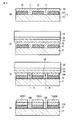
図1は、本実施の形態に係るシースルー型太陽電池モジュールの加飾物の断面形状を模式的に示すものである。
Hereinafter, embodiments of the present invention will be described with reference to the drawings.
FIG. 1 schematically shows a cross-sectional shape of a decoration of a see-through solar cell module according to the present embodiment.
本実施の形態に係るシースルー型太陽電池モジュール10は、硝子基板11上に複数の光電変換素子12が所定間隔あけて形成されていて、硝子基板11の表面16側に照射された外光9により光電変換して発電している。
近接する光電変換素子12間には、光透過性のある開口部17が設けられ、この開口部17から外光9が透過し、外光9を室内の照明光として使用できるようになっている。
In the see-through
A light-transmitting
シースルー型太陽電池モジュール10の背面15の全面に感光性を有する粘着材からなる粘着層13が形成されている。
An
シースルー型太陽電池モジュール10の背面15が室内側に配置され、シースルー型太陽電池モジュール10の背面15側である光電変換素子12の最表面には発電効果がなく、この光電変換素子12上のみ選択的に色材14を貼り合せて、室内側に加飾を施した加飾物としている。
The
粘着層13を形成する感光性の粘着材としては、紫外線域に反応の輝線を有するもので、アクリル系樹脂、シリコン系樹脂、ウレタン系樹脂、エポキシ系樹脂、チオール系樹脂などが使用可能である。
The photosensitive adhesive material for forming the
粘着層13の厚みとしては、光反応の伝達性を考慮し、光電変換素子12の開口部17の1/2以下、望ましくは50μmt以下が望ましい。
粘着材の塗工方法としては、シースルー型太陽電池モジュール10に直接塗工する方法と、剥離紙上に塗工した後シースルー型太陽電池モジュ−ル10に転写する方法が可能である。
The thickness of the
As a method for applying the adhesive material, a method of directly applying to the see-through type
シースルー型太陽電池モジュール10としての電気的導通部を確保したり、加飾を必要とするエリアに選択的に加飾を施すためには、所定のパターンのスクリーン版を使用し、前記粘着材をスクリーン印刷することが望ましい。
In order to secure an electrically conducting portion as the see-through
色材としては転写箔や分体状のものが使用可能であるが、製造装置の簡略化や、製造環境のクリーン化のためには、転写箔の使用が望ましい。
転写箔の箔切れへの影響を与える因子として、転写箔と離形紙との密着力と、転写箔の横方向の膜として凝集力が上げられる。
As the coloring material, a transfer foil or a divided material can be used. However, in order to simplify the manufacturing apparatus and clean the manufacturing environment, it is preferable to use the transfer foil.
Factors affecting the transfer foil, such as the adhesive force between the transfer foil and the release paper, and the cohesive force as a lateral film of the transfer foil.
転写箔と粘着材の密着は、転写箔と離形紙との密着力より高い事が望ましい。
転写箔の横方向の膜として凝集力は低い程が望ましく、凝集力を低くするために転写箔の膜厚は5μmt以下が望ましい。
The adhesion between the transfer foil and the adhesive material is preferably higher than the adhesion between the transfer foil and the release paper.
It is desirable that the cohesive force is low as the film in the lateral direction of the transfer foil. In order to reduce the cohesive force, the film thickness of the transfer foil is desirably 5 μmt or less.
図2に示すように、光電変換素子12の遮光性と開口部17の透過率を利用して、光電変換素子12を露光用マスクとして使用し、粘着層13を裏面から露光光線18により露光することで、光電変換素子12の形成されていない光電変換素子12間の開口部17に位置する粘着層13の粘着性を低下させ、光電変換素子12上の粘着部13Aおよび開口部17上の非粘着部13Bを形成している。
As shown in FIG. 2, the
これにより、光電変換素子12間の開口部17の基板ごとの加工位置精度によらず、光電変換素子12上のみに選択的に粘着部13Aを形成することができ、かつ、その上に色材14を貼り合せることで、採光性を低下させることなく、色や絵柄などの高い意匠性を有する加飾を施したシースルー型太陽電池モジュール10を得ることができる。
Accordingly, the
以下、実施例について図3を参照して説明する。
シースルー型太陽電池モジュール10として、光電変換素子12の分光透過率が0%、開口部17の分光透過率が90%、光電変換素子12のパターンの幅が1000μm、光電変換素子12間の開口部17の幅が90μm、硝子基板11がソーダ硝子からなるものを使用した。
Hereinafter, an embodiment will be described with reference to FIG.
As the see-through
粘着材としては、アクリル系樹脂からなるラジカル重合型の感光性樹脂からなる、シート抵抗1014Ω/□の材料を使用した。
色材としては、有機樹脂にカーボンブラックを分散したインキをシリコン系の剥離紙上に、膜厚1μmにて塗工乾燥して形成した転写箔を使用した。
As the adhesive material, a material having a sheet resistance of 10 14 Ω / □ made of a radical polymerization type photosensitive resin made of an acrylic resin was used.
As the color material, a transfer foil formed by coating and drying an ink in which carbon black was dispersed in an organic resin on a silicon-based release paper with a film thickness of 1 μm was used.
シースルー型太陽電池モジュール10の背面15側の、光電変換機能の無い光電変換素子12の表面上へ選択的に墨単色の加飾を施すために、
(1)図3(a)に示すように、シースルー型太陽電池モジュール10の背面15に前記粘着材をスクリーン印刷により膜厚10μmで塗工、乾燥することにより粘着層13を形成した。
In order to selectively decorate black ink on the surface of the
(1) As shown in FIG. 3A, the
(2)次に、図3(b)に示すように、粘着層13の上に、剥離層21を有する剥離紙22を介して転写箔23をラミネートすることにより貼り合せた。
(2) Next, as shown in FIG. 3 (b), the
(3)次に、図3(c)に示すように、シースルー型太陽電池モジュール10の表面16側から露光光線18により所定の露光量を照射し、粘着層13の光電変換素子12間の開口部17の粘着性を低下させることにより、光電変換素子12上の粘着部13Aと開口部17上の非粘着部13Bを形成した。
(3) Next, as shown in FIG. 3 (c), a predetermined exposure dose is irradiated from the
(4)次に、図3(d)に示すように、剥離紙22と転写箔23とを剥離し、光電変換素子12上の粘着部13Aのみに転写箔23からなるパターン14を定着させた。
(4) Next, as shown in FIG. 3D, the
なお、上記(2)の工程と上記(3)の工程とを入れ替えてもよい。すなわち、上記(3)の工程を先に行い、その次に上記(2)の工程を行なうようにしてもよい。 The step (2) and the step (3) may be interchanged. That is, the step (3) may be performed first, and then the step (2) may be performed.
上記した本発明の加飾方法により、光電変換素子12間の開口部17の基板11ごとの加工位置精度によらず、光電変換素子12上のみに選択的に色材14を貼り合せることで、採光性を低下させることなく、電気的に絶縁性が高く、かつ、墨単色の意匠からなる加飾を施したシースルー型太陽電池モジュール10を得ることができた。
By the above-described decoration method of the present invention, the
以下、比較例について図4を参照して説明する。
シースルー型太陽電池モジュール10として、光電変換素子12の分光透過率が0%、開口部17の分光透過率が90%、光電変換素子12のパターンの幅が1000μm、光電変換素子12間の開口部17の幅が90μm、硝子基板11がソーダ硝子からなるものを使用した。
Hereinafter, a comparative example will be described with reference to FIG.
As the see-through
粘着材としては、アクリル系樹脂からなるラジカル重合型の感光性樹脂からなる、シート抵抗1014Ω/□の材料を使用した。
色材としては、有機樹脂にカーボンブラックを分散したインキをシリコン系の剥離紙上に、膜厚1μmにて塗工乾燥して形成した転写箔を使用した。
露光用のマスクとして、光電変換素子12の形状にパターンを形成したCrマスクを使用した。
As the adhesive material, a material having a sheet resistance of 10 14 Ω / □ made of a radical polymerization type photosensitive resin made of an acrylic resin was used.
As the color material, a transfer foil formed by coating and drying an ink in which carbon black was dispersed in an organic resin on a silicon-based release paper with a film thickness of 1 μm was used.
A Cr mask in which a pattern was formed in the shape of the
シースルー型太陽電池モジュール10の背面15側の、光電変換機能の無い光電変換素子12の表面上へ選択的に墨単色の加飾を施すために、
(1)図4(a)に示すように、シースルー型太陽電池モジュール10の背面15に前記粘着材をスクリーン印刷により膜厚10μmで塗工、乾燥することにより粘着層13を形成した。
In order to selectively decorate black ink on the surface of the
(1) As shown in FIG. 4A, the
(2)次に、図4(b)に示すように、シースルー型太陽電池モジュール10の背面15側に、光電変換素子12の形状にパターン31を形成した露光用マスク32をアライメントマークにて位置合わせを行なった。
(2) Next, as shown in FIG. 4B, an
(3)次に、図4(b)に示すように、シースルー型太陽電池モジュール10の背面16側から露光用マスク32を介して露光光線18により所定の露光量を照射し、粘着層13の光電変換素子12間の開口部17の粘着性を低下させることにより、光電変換素子12上の粘着部13Aと開口部17上の非粘着部13Bを形成した。
(3) Next, as shown in FIG. 4 (b), a predetermined exposure amount is irradiated from the
(4)次に、図4(c)に示すように、粘着層13の上に、剥離層21を有する剥離紙22を介して転写箔23をラミネートすることにより貼り合せた。
(4) Next, as shown in FIG. 4C, the
(5)次に、図4(d)に示すように、剥離紙22と転写箔23とを剥離し、光電変換素子12上の粘着部13Aのみに転写箔23からなるパターン14を定着させた。
(5) Next, as shown in FIG. 4D, the
上記した比較例では、シースルー型太陽電池モジュール10の開口部17を形成する際の加工精度の再現性が低く、安定した加工精度が得られる露光用マスク32の位置精度と一致せず、図4(d)に示すように、シースルー型太陽電池モジュール10の開口部17の一部を転写箔23のパターン14が覆う部分が発生し、採光性を低下させてしまう。
In the comparative example described above, the reproducibility of the processing accuracy when forming the
本発明の加飾物およびその加飾方法は、本発明のシースルー型太陽電池モジュール以外に、店頭POPや硝子窓などの表裏面で視認されるディスプレイにおいて表裏で絵柄の異なる加飾を施すことに応用できる。 In addition to the see-through solar cell module of the present invention, the decorative object of the present invention and the method of decorating the same are applied to decorating with different patterns on the front and back of a display that is visible on the front and back surfaces such as a storefront POP and a glass window. it can.
10…シースルー型太陽電池モジュール、11…硝子基板、12…光電変換素子、13…粘着層、14…色材パターン、15…シースルー型太陽電池モジュールの背面、16…シースルー型太陽電池モジュールの表面、17…開口部、18…露光光線、21…離形層、22…剥離紙、23…転写箔、32…露光用マスク。
DESCRIPTION OF
Claims (9)
前記粘着層の上に転写箔を形成した剥離紙をラミネートする工程と、
前記シースルー型太陽電池モジュールの表面から露光し、光電変換素子の形成されていない光電変換素子間の開口部に位置する粘着層の粘着性を低下させることにより、光電変換素子上の粘着部および前記開口部上の非粘着部を形成する工程と、
前記剥離紙と転写箔を剥離し、前記粘着部のみに前記転写箔からなるパターンを形成する工程と、
を具備したことを特徴とするシースルー型太陽電池モジュールの加飾方法。 Forming an adhesive layer made of an adhesive material having photosensitivity on the back surface of a see-through solar cell module having a photoelectric conversion function;
Laminating a release paper having a transfer foil formed on the adhesive layer;
By exposing from the surface of the see-through solar cell module and reducing the adhesiveness of the adhesive layer located in the opening between the photoelectric conversion elements where the photoelectric conversion elements are not formed, the adhesive part on the photoelectric conversion element and the above Forming a non-adhesive portion on the opening;
Peeling the release paper and transfer foil and forming a pattern made of the transfer foil only on the adhesive part;
A decoration method for a see-through solar cell module, comprising:
前記シースルー型太陽電池モジュールの表面から露光し、光電変換素子の形成されていない光電変換素子間の開口部に位置する粘着層の粘着性を低下させることにより、光電変換素子上の粘着部および前記開口部上の非粘着部を形成する工程と、
前記粘着層の上に転写箔を形成した剥離紙をラミネートする工程と、
前記剥離紙と転写箔を剥離し、前記粘着部のみに前記転写箔からなるパターンを形成する工程と、
を具備したことを特徴とするシースルー型太陽電池モジュールの加飾方法。 Forming an adhesive layer made of an adhesive material having photosensitivity on the back surface of a see-through solar cell module having a photoelectric conversion function;
By exposing from the surface of the see-through solar cell module and reducing the adhesiveness of the adhesive layer located in the opening between the photoelectric conversion elements where the photoelectric conversion elements are not formed, the adhesive part on the photoelectric conversion element and the above Forming a non-adhesive portion on the opening;
Laminating a release paper having a transfer foil formed on the adhesive layer;
Peeling the release paper and transfer foil and forming a pattern made of the transfer foil only on the adhesive part;
A decoration method for a see-through solar cell module, comprising:
光電変換機能を有するシースルー型太陽電池モジュールの背面に前記粘着層と転写箔を積層形成した剥離紙をラミネートする工程と、
前記シースルー型太陽電池モジュールの表面から露光し、光電変換素子の形成されていない光電変換素子間の開口部に位置する粘着層の粘着性を低下させることにより、前記粘着層に粘着部および非粘着部を形成する工程と、
前記剥離紙と転写箔を剥離し、前記粘着部のみに前記転写箔からなるパターンを形成する工程と、
を具備したことを特徴とするシースルー型太陽電池モジュールの加飾方法。 Forming an adhesive layer made of an adhesive material having photosensitivity on the release paper on which the transfer foil is formed;
Laminating a release paper in which the adhesive layer and the transfer foil are laminated on the back surface of a see-through solar cell module having a photoelectric conversion function;
By exposing from the surface of the see-through solar cell module and lowering the adhesiveness of the adhesive layer located in the opening between the photoelectric conversion elements where the photoelectric conversion elements are not formed, the adhesive layer and the non-adhesive in the adhesive layer Forming a part;
Peeling the release paper and transfer foil and forming a pattern made of the transfer foil only on the adhesive part;
A decoration method for a see-through solar cell module, comprising:
前記シースルー型太陽電池モジュールの表面から露光し、光電変換素子の形成されていない光電変換素子間の開口部に位置する粘着層の粘着性を低下させることにより、光電変換素子上の粘着部および前記開口部上の非粘着部を形成する工程と、
前記粘着層の全面に粉体状の色材を散布した後、余剰の粉体状の色材を除去し、前記粘着部のみに前記粉体状の色材からなるパターンを形成する工程と、
を具備したことを特徴とするシースルー型太陽電池モジュールの加飾方法。 Forming an adhesive layer made of an adhesive material having photosensitivity on the back surface of a see-through solar cell module having a photoelectric conversion function;
By exposing from the surface of the see-through solar cell module and reducing the adhesiveness of the adhesive layer located in the opening between the photoelectric conversion elements where the photoelectric conversion elements are not formed, the adhesive part on the photoelectric conversion element and the above Forming a non-adhesive portion on the opening;
After spraying powdery color material over the entire surface of the adhesive layer, removing excess powdery color material, forming a pattern made of the powdery color material only on the adhesive part; and
A decoration method for a see-through solar cell module, comprising:
Priority Applications (1)
| Application Number | Priority Date | Filing Date | Title |
|---|---|---|---|
| JP2010283544A JP5573652B2 (en) | 2010-12-20 | 2010-12-20 | Decoration method for see-through solar cell module |
Applications Claiming Priority (1)
| Application Number | Priority Date | Filing Date | Title |
|---|---|---|---|
| JP2010283544A JP5573652B2 (en) | 2010-12-20 | 2010-12-20 | Decoration method for see-through solar cell module |
Publications (2)
| Publication Number | Publication Date |
|---|---|
| JP2012134241A true JP2012134241A (en) | 2012-07-12 |
| JP5573652B2 JP5573652B2 (en) | 2014-08-20 |
Family
ID=46649518
Family Applications (1)
| Application Number | Title | Priority Date | Filing Date |
|---|---|---|---|
| JP2010283544A Expired - Fee Related JP5573652B2 (en) | 2010-12-20 | 2010-12-20 | Decoration method for see-through solar cell module |
Country Status (1)
| Country | Link |
|---|---|
| JP (1) | JP5573652B2 (en) |
Cited By (4)
| Publication number | Priority date | Publication date | Assignee | Title |
|---|---|---|---|---|
| JP2016066757A (en) * | 2014-09-25 | 2016-04-28 | 積水ハウス株式会社 | Solar battery module, wall surface structure, and house |
| KR20190051024A (en) * | 2016-09-20 | 2019-05-14 | 가부시키가이샤 가네카 | Glass building material |
| WO2020096329A1 (en) * | 2018-11-08 | 2020-05-14 | 주식회사 포스코 | Composition for coating glass for photovoltaic module and photovoltaic module comprising coating layer formed of composition |
| EP3840059A1 (en) * | 2019-12-19 | 2021-06-23 | Nederlandse Organisatie voor toegepast- natuurwetenschappelijk Onderzoek TNO | Semi-translucent photovoltaic device and method of manufacturing the same |
Citations (7)
| Publication number | Priority date | Publication date | Assignee | Title |
|---|---|---|---|---|
| JPS52165159U (en) * | 1976-06-08 | 1977-12-14 | ||
| JPS5711056U (en) * | 1980-06-20 | 1982-01-20 | ||
| JPS601000A (en) * | 1983-06-02 | 1985-01-07 | ホモフア−ベルデザイン株式会社 | Transfer sheet |
| JPH04308797A (en) * | 1991-04-08 | 1992-10-30 | Kimoto & Co Ltd | Partially irregular image indication matter and method for forming partially irregular image |
| JPH07164796A (en) * | 1991-03-25 | 1995-06-27 | Masahiro Abe | Chromatic transfering method on glass plate |
| JP2002319694A (en) * | 2001-04-20 | 2002-10-31 | Sharp Corp | Solar battery module having light-gathering laminated glass structure and solar battery module having light gathering type double-layered structure |
| JP2008072004A (en) * | 2006-09-15 | 2008-03-27 | Msk Corp | Transmission-type solar light generating apparatus |
-
2010
- 2010-12-20 JP JP2010283544A patent/JP5573652B2/en not_active Expired - Fee Related
Patent Citations (7)
| Publication number | Priority date | Publication date | Assignee | Title |
|---|---|---|---|---|
| JPS52165159U (en) * | 1976-06-08 | 1977-12-14 | ||
| JPS5711056U (en) * | 1980-06-20 | 1982-01-20 | ||
| JPS601000A (en) * | 1983-06-02 | 1985-01-07 | ホモフア−ベルデザイン株式会社 | Transfer sheet |
| JPH07164796A (en) * | 1991-03-25 | 1995-06-27 | Masahiro Abe | Chromatic transfering method on glass plate |
| JPH04308797A (en) * | 1991-04-08 | 1992-10-30 | Kimoto & Co Ltd | Partially irregular image indication matter and method for forming partially irregular image |
| JP2002319694A (en) * | 2001-04-20 | 2002-10-31 | Sharp Corp | Solar battery module having light-gathering laminated glass structure and solar battery module having light gathering type double-layered structure |
| JP2008072004A (en) * | 2006-09-15 | 2008-03-27 | Msk Corp | Transmission-type solar light generating apparatus |
Cited By (8)
| Publication number | Priority date | Publication date | Assignee | Title |
|---|---|---|---|---|
| JP2016066757A (en) * | 2014-09-25 | 2016-04-28 | 積水ハウス株式会社 | Solar battery module, wall surface structure, and house |
| KR20190051024A (en) * | 2016-09-20 | 2019-05-14 | 가부시키가이샤 가네카 | Glass building material |
| US20190211617A1 (en) * | 2016-09-20 | 2019-07-11 | Kaneka Corporation | Glass building material |
| KR102201587B1 (en) * | 2016-09-20 | 2021-01-12 | 가부시키가이샤 가네카 | Glass building materials |
| US10920482B2 (en) | 2016-09-20 | 2021-02-16 | Kaneka Corporation | Glass building material |
| WO2020096329A1 (en) * | 2018-11-08 | 2020-05-14 | 주식회사 포스코 | Composition for coating glass for photovoltaic module and photovoltaic module comprising coating layer formed of composition |
| EP3840059A1 (en) * | 2019-12-19 | 2021-06-23 | Nederlandse Organisatie voor toegepast- natuurwetenschappelijk Onderzoek TNO | Semi-translucent photovoltaic device and method of manufacturing the same |
| WO2021125964A1 (en) * | 2019-12-19 | 2021-06-24 | Nederlandse Organisatie Voor Toegepast- Natuurwetenschappelijk Onderzoek Tno | Semi-translucent photovoltaic device and method of manufacturing the same |
Also Published As
| Publication number | Publication date |
|---|---|
| JP5573652B2 (en) | 2014-08-20 |
Similar Documents
| Publication | Publication Date | Title |
|---|---|---|
| US20210043787A1 (en) | Decorated photovoltaic cell module | |
| JP3919468B2 (en) | Thin film solar cell module and thin film solar cell panel | |
| CN102792465B (en) | The method of mask thickener and the thin film photovoltaic panel for the manufacture of partially transparent | |
| KR102360087B1 (en) | Color film applied solar module and manufacturing method thereof | |
| CN215578586U (en) | Photovoltaic module with colored cloth line coating of high printing opacity | |
| JP5573652B2 (en) | Decoration method for see-through solar cell module | |
| CN110073170A (en) | The camouflage solar panel of screen type color-match | |
| US20120118367A1 (en) | Non-planar/curved dye-sensitized solar cell and a method of manufacturing the same | |
| JP2021508178A (en) | Solar cell | |
| CN113097322B (en) | High-light-transmittance color solar panel, production method thereof and color solar photovoltaic module | |
| CN217588951U (en) | Photovoltaic module with high printing opacity granite effect panel | |
| JP4920105B2 (en) | Light transmissive solar cell module, method for manufacturing the same, and moving body equipped with the light transmissive solar cell module | |
| TW201717416A (en) | Colorful solar power module and manufacturing method thereof | |
| WO2016095977A1 (en) | Solar module and its production process | |
| CN111769174A (en) | Black photovoltaic module and preparation method thereof | |
| Ram et al. | Directly patterned TiO2 nanostructures for efficient light harvesting in thin film solar cells | |
| JP2000091609A (en) | Manufacture of organic solar battery | |
| CN104718628A (en) | Solar module and its production process | |
| CN112117340A (en) | Preparation method of solar module | |
| CN217173596U (en) | Colored photovoltaic packaging adhesive film | |
| JP5372184B2 (en) | Full-color image thin film solar cell and manufacturing method thereof | |
| CN211716521U (en) | Single-color dynamic LED photoelectric glass | |
| NL2019628B1 (en) | Photovoltaic module having scattering patterns | |
| JP3746411B2 (en) | Solar cell panel and manufacturing method thereof | |
| KR20090102912A (en) | Solar Cell Modules Having Designed Decorating Portions and the Manufacturing Method thereof |
Legal Events
| Date | Code | Title | Description |
|---|---|---|---|
| A621 | Written request for application examination |
Free format text: JAPANESE INTERMEDIATE CODE: A621 Effective date: 20131121 |
|
| A977 | Report on retrieval |
Free format text: JAPANESE INTERMEDIATE CODE: A971007 Effective date: 20140224 |
|
| A131 | Notification of reasons for refusal |
Free format text: JAPANESE INTERMEDIATE CODE: A131 Effective date: 20140304 |
|
| A521 | Request for written amendment filed |
Free format text: JAPANESE INTERMEDIATE CODE: A523 Effective date: 20140507 |
|
| TRDD | Decision of grant or rejection written | ||
| A01 | Written decision to grant a patent or to grant a registration (utility model) |
Free format text: JAPANESE INTERMEDIATE CODE: A01 Effective date: 20140603 |
|
| A61 | First payment of annual fees (during grant procedure) |
Free format text: JAPANESE INTERMEDIATE CODE: A61 Effective date: 20140616 |
|
| R150 | Certificate of patent or registration of utility model |
Ref document number: 5573652 Country of ref document: JP Free format text: JAPANESE INTERMEDIATE CODE: R150 |
|
| LAPS | Cancellation because of no payment of annual fees |