JP2012128230A - Noise suppressor for air introduction pipe - Google Patents

Noise suppressor for air introduction pipe Download PDF

Info

Publication number
JP2012128230A
JP2012128230A JP2010280219A JP2010280219A JP2012128230A JP 2012128230 A JP2012128230 A JP 2012128230A JP 2010280219 A JP2010280219 A JP 2010280219A JP 2010280219 A JP2010280219 A JP 2010280219A JP 2012128230 A JP2012128230 A JP 2012128230A
Authority
JP
Japan
Prior art keywords
silencer
frequency
opening
resonator
cylindrical portion
Prior art date
Legal status (The legal status is an assumption and is not a legal conclusion. Google has not performed a legal analysis and makes no representation as to the accuracy of the status listed.)
Pending
Application number
JP2010280219A
Other languages
Japanese (ja)
Inventor
Shinichi Kato
信一 加藤
Yasuhito Tanase
廉人 棚瀬
Current Assignee (The listed assignees may be inaccurate. Google has not performed a legal analysis and makes no representation or warranty as to the accuracy of the list.)
Yamaha Corp
Original Assignee
Yamaha Corp
Priority date (The priority date is an assumption and is not a legal conclusion. Google has not performed a legal analysis and makes no representation as to the accuracy of the date listed.)
Filing date
Publication date
Application filed by Yamaha Corp filed Critical Yamaha Corp
Priority to JP2010280219A priority Critical patent/JP2012128230A/en
Publication of JP2012128230A publication Critical patent/JP2012128230A/en
Pending legal-status Critical Current

Links

Images

Classifications

    • YGENERAL TAGGING OF NEW TECHNOLOGICAL DEVELOPMENTS; GENERAL TAGGING OF CROSS-SECTIONAL TECHNOLOGIES SPANNING OVER SEVERAL SECTIONS OF THE IPC; TECHNICAL SUBJECTS COVERED BY FORMER USPC CROSS-REFERENCE ART COLLECTIONS [XRACs] AND DIGESTS
    • Y02TECHNOLOGIES OR APPLICATIONS FOR MITIGATION OR ADAPTATION AGAINST CLIMATE CHANGE
    • Y02EREDUCTION OF GREENHOUSE GAS [GHG] EMISSIONS, RELATED TO ENERGY GENERATION, TRANSMISSION OR DISTRIBUTION
    • Y02E60/00Enabling technologies; Technologies with a potential or indirect contribution to GHG emissions mitigation
    • Y02E60/30Hydrogen technology
    • Y02E60/50Fuel cells

Abstract

PROBLEM TO BE SOLVED: To surely reduce noises which are line-spectral and the peak frequency of which appears at constant intervals over a wide band.SOLUTION: One opening 2 of a pipe conduit 4 is connected to a noise source 90. A silencer type silencer 10 is provided at a distance λ/4 from the other opening 3 toward the opening 2 of the pipe conduit 4. A silencer type silencer 20 is provided at a distance λ/4 from the opening 3 toward the opening 2 of the pipe conduit 4. A silencer type silencer 30 is provided at a distance λ/4 from the opening 3 toward the opening 2 of the pipe conduit 4. An expansion type silencer 40 is provided between the silencer 30 and the opening 3 in the pipe conduit 4.

Description

本発明は、燃料電池(DMFC:Direct Methanol Fuel Cell)等に空気を導入する空気導入管における騒音の静音化に好適な静音化装置に関する。   The present invention relates to a noise reduction device suitable for noise reduction in an air introduction pipe that introduces air into a fuel cell (DMFC) or the like.

電子楽器やPA(Pro Audio)機器の電源としての用途が期待される技術の1つに直接メタノール型燃料電池がある。図32は、この電池80の構成を示す図である。図32に示すように、直接メタノール型燃料電池80は、燃料電池セル81と、燃料電池セル81における一方の極である空気極82に空気を供給する空気ポンプ84と、燃料電池セル81における他方の極である燃料極83にメタノールを供給する燃料ポンプ85と、燃料電池セル81において空気とメタノールとが化学反応を起こすことにより発生する水を廃棄するラジエータ86と、メタノールを循環させるラジエータ87とを有する。この電池80の空気極82及び燃料極83に電子機器やPA機器などの負荷89を接続し、空気極82及び燃料極83に空気及びメタノールを供給すると、空気及びメタノールの化学反応により発生した電力が負荷89に与えられる。ここで、この電池80の駆動中には、空気ポンプ84内のモータが定速で回転され、外部の空気が同ポンプ84を介して空気極82へ送り込まれる。このため、図33に示すように、この電池80の駆動中は、モータの回転数の整数倍の周波数に急峻なピークを持った複数の線スペクトルを含む騒音が、空気ポンプ84から発生する。このように広い周波数帯域に亙って多くの線スペクトルの分布した音の静音化に利用できる技術的手段として、騒音源に管路を連結し、この管路上に膨張型消音器や共鳴器型消音器などの消音器を備えつけたものがある(例えば、特許文献1を参照)。   One of the technologies expected to be used as a power source for electronic musical instruments and PA (Pro Audio) devices is a direct methanol fuel cell. FIG. 32 is a diagram showing a configuration of the battery 80. As shown in FIG. 32, a direct methanol fuel cell 80 includes a fuel cell 81, an air pump 84 that supplies air to an air electrode 82 that is one of the electrodes in the fuel cell 81, and the other in the fuel cell 81. A fuel pump 85 for supplying methanol to the fuel electrode 83, a radiator 86 for discarding water generated by a chemical reaction between air and methanol in the fuel cell 81, and a radiator 87 for circulating methanol Have When a load 89 such as an electronic device or a PA device is connected to the air electrode 82 and the fuel electrode 83 of the battery 80 and air and methanol are supplied to the air electrode 82 and the fuel electrode 83, electric power generated by a chemical reaction between the air and methanol. Is applied to the load 89. Here, while the battery 80 is being driven, the motor in the air pump 84 is rotated at a constant speed, and external air is sent to the air electrode 82 via the pump 84. Therefore, as shown in FIG. 33, while the battery 80 is being driven, noise including a plurality of line spectra having a steep peak at a frequency that is an integral multiple of the rotational speed of the motor is generated from the air pump 84. As a technical means that can be used to silence the sound with many line spectra distributed over such a wide frequency band, a pipe line is connected to a noise source, and an expansion silencer or resonator type is connected to this pipe line. Some have a silencer such as a silencer (see, for example, Patent Document 1).

膨張型消音器は、管路の途中に、管路の内側の断面積よりも大きな断面積の空洞を内側に持った膨張部を設け、管路及び膨張部の断面積の不連続な部分で生じる反射によって伝搬音を減衰させるものである。図34は、膨張型消音器300の構成を示す図である。共鳴器型消音器は、管路の途中に閉管やヘルムホルツ共鳴器などの各種共鳴器を連結したものである。図35は、ヘルムホルツ共鳴器を用いた共鳴器型消音器301の構成を示す図である。   An inflatable silencer is provided with an inflating part having a cavity with a cross-sectional area larger than the inner cross-sectional area inside the pipe in the middle of the pipe. The reflected sound is attenuated by the generated reflection. FIG. 34 is a diagram illustrating a configuration of the expansion silencer 300. The resonator type silencer is obtained by connecting various resonators such as a closed tube and a Helmholtz resonator in the middle of a pipe line. FIG. 35 is a diagram showing a configuration of a resonator type silencer 301 using a Helmholtz resonator.

膨張型消音器の管路の入口及び出口間における各周波数成分の透過損失Rは、管路長が無限大であると仮定した場合、次式(1)により求められ、図36(A)のようになる。次式(1)において、mは、膨張部内の空洞の面積S2を膨張部に繋がる一方の側の管路の断面積S1で除算した値である。m’は、膨張部内の空洞の面積S2を膨張部に繋がる他方の管路の断面積S3で除算した値である。kは、管路を伝搬する音の波数(=2π/波長)である。lは、膨張型消音器における空洞部の長さである。

Figure 2012128230
The transmission loss R of each frequency component between the inlet and outlet of the pipe of the expansion silencer can be obtained by the following equation (1) when the pipe length is assumed to be infinite, as shown in FIG. It becomes like this. In the following equation (1), m is a value obtained by dividing the area S2 of the cavity in the expansion part by the cross-sectional area S1 of the pipe line on one side connected to the expansion part. m ′ is a value obtained by dividing the area S2 of the cavity in the expansion part by the cross-sectional area S3 of the other pipe connected to the expansion part. k is the wave number (= 2π / wavelength) of the sound propagating through the pipeline. l is the length of the cavity in the expansion silencer.
Figure 2012128230

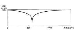
また、例えば、共鳴器型消音器が図35に示す構成のもの(ヘルムホルツ共鳴器を利用したもの)である場合、透過損失Rは、次式(2)により求められ、図37のようになる。式(2)において、Vはヘルムホルツ共鳴器のキャビティの容積、Sは管路の断面積、fは管路を伝搬する音の周波数、frはヘルムホルツ共鳴器の共鳴周波数である。

Figure 2012128230
式(2)における共鳴周波数frは、次式(3)により与えられる。
Figure 2012128230
次式(3)において、Cは、音速である。また、式(2)及び(3)におけるCは、次式(4)により与えられる。
Figure 2012128230
式(4)において、nはキャビティと管路の連結孔であるネックの個数、aはネックの半径、lはネックの長さである。また、βは次式(5)により与えられる。
Figure 2012128230
Further, for example, when the resonator type silencer has the configuration shown in FIG. 35 (using a Helmholtz resonator), the transmission loss R is obtained by the following equation (2), as shown in FIG. . In Equation (2), V is the volume of the cavity of the Helmholtz resonator, S is the cross-sectional area of the pipe, f is the frequency of the sound propagating through the pipe, and fr is the resonance frequency of the Helmholtz resonator.
Figure 2012128230
The resonance frequency fr in the equation (2) is given by the following equation (3).
Figure 2012128230
In the following equation (3), C is the speed of sound. Further, C 0 in the equations (2) and (3) is given by the following equation (4).
Figure 2012128230
In the formula (4), n is the number of neck is a coupling hole of the cavity and the flow path, a is the radius of the neck, the l e is the length of the neck. Β is given by the following equation (5).
Figure 2012128230

図36(A)に示すように、膨張型消音器における透過損失×(−1)で見積もった伝達関数においては、前掲の式(1)におけるパラメータm,m’,k,lにより決まる一定の周波数帯域幅毎に急峻なピークが現れる。そして、この伝達関数においては、ピークとピークの間の周波数の利得が小さくなる。また、図37に示すように、共鳴器型消音器における透過損失×(−1)で見積もった伝達関数は、共鳴器のパラメータ(図35の例の消音器であれば、キャビティの容積、キャビティと管路とを連結するネックの面積、ネックの長さ)により決まる1つの周波数に急峻なディップを持ったものとなる。よって、原理的には、当該膨張型消音器における透過損失×(−1)で見積もった伝達関数のピークの周波数が騒音のピークの周波数と一致しないような寸法とした膨張型消音器を利用したり、各々の透過損失×(−1)で見積もった伝達関数のディップの周波数が騒音のピークの周波数と一致するような寸法とした複数個の共鳴器型消音器を利用することにより、直接メタノール型燃料電池の空気ポンプから発生する騒音を静音化することが可能ではある。   As shown in FIG. 36 (A), in the transfer function estimated by transmission loss × (−1) in the expansion silencer, a constant determined by the parameters m, m ′, k, and l in the above equation (1). A steep peak appears for each frequency bandwidth. And in this transfer function, the gain of the frequency between peaks becomes small. As shown in FIG. 37, the transfer function estimated by transmission loss in the resonator-type silencer × (−1) is a parameter of the resonator (for the silencer in the example of FIG. 35, the volume of the cavity, the cavity And a pipe having a steep dip at one frequency determined by the neck area and the neck length). Therefore, in principle, an expansion silencer having a size such that the peak frequency of the transfer function estimated by transmission loss × (−1) in the expansion silencer does not coincide with the noise peak frequency is used. Or by using a plurality of resonator-type silencers sized so that the dip frequency of the transfer function estimated by each transmission loss × (−1) matches the frequency of the noise peak. The noise generated from the air pump of the fuel cell can be silenced.

特開2003−166689号公報JP 2003166666 A

しかしながら、このような技術的手段には次のような問題がある。まず、図36(A)に示した膨張型消音器における透過損失×(−1)で見積もった伝達関数は、膨張部の両側に無限長の管路が各々繋がっていると仮定した場合のものであるが、実際には、有限の長さの管路が膨張部の両側に接続される。このため、図36(B)に示すように、膨張型消音器における透過損失×(−1)で見積もった伝達関数は、ピークの周波数の間隔が不均一なものとなる。そして、膨張型消音器の管路の長さが有限である場合における透過損失×(−1)で見積もった伝達関数のピークの周波数は、膨張部内の空洞の断面積や膨張部の両端に繋がる各管路の形状(管路の断面積、管路の屈曲の有無、管路の枝分かれの有無、継手などの介在の有無など)といった様々な条件に依存して決まる。このため、膨張型消音器を、その伝達関数のピークの周波数が狙いとする騒音のピークの周波数のいずれとも一致しないように設計することは極めて困難である。   However, such technical means have the following problems. First, the transfer function estimated by transmission loss × (−1) in the expansion silencer shown in FIG. 36 (A) is based on the assumption that infinitely long pipelines are connected to both sides of the expansion portion. In practice, however, a finite length of conduit is connected to both sides of the inflating portion. For this reason, as shown in FIG. 36B, the transfer function estimated by transmission loss × (−1) in the expansion silencer has a nonuniform peak frequency interval. The peak frequency of the transfer function estimated by transmission loss × (−1) when the length of the pipe of the expansion silencer is finite is connected to the cross-sectional area of the cavity in the expansion section and both ends of the expansion section. It is determined depending on various conditions such as the shape of each pipe (cross-sectional area of the pipe, whether or not the pipe is bent, whether or not the pipe is branched, and whether or not a joint is interposed). For this reason, it is extremely difficult to design the expansion silencer so that the peak frequency of the transfer function does not coincide with any of the target noise peak frequencies.

一方、共鳴器型消音器における透過損失×(−1)で見積もった伝達関数のディップの周波数は、当該共鳴器型消音器の共鳴周波数を決めるパラメータとなる数種類の寸法(図35の例の消音器であれば、キャビティの容積V、キャビティと管路とを連結するネックの面積S、ネックの長さl)に依存するため、伝達関数のディップの周波数が狙いとする騒音のピークの周波数と一致するように設計することは、膨張型消音器に比べれば容易である。しかしながら、共鳴器型消音器における透過損失×(−1)で見積もった伝達関数のディップは急峻であるから、空気ポンプ84の駆動中の温度変化などにより空気ポンプ84から発生する騒音のピークの周波数が僅かでも変化すると、静音効果が得られなくなる。 On the other hand, the dip frequency of the transfer function estimated by transmission loss in the resonator type silencer × (−1) is several types of dimensions (the silence in the example of FIG. 35) that are parameters for determining the resonance frequency of the resonator type silencer. In this case, since it depends on the volume V of the cavity, the area S of the neck connecting the cavity and the pipe, and the length l e of the neck, the frequency of the dip of the transfer function is the target frequency of the peak of the noise. It is easier to design so as to match with the expansion silencer. However, since the dip of the transfer function estimated by transmission loss × (−1) in the resonator type silencer is steep, the frequency of the peak of noise generated from the air pump 84 due to a temperature change during driving of the air pump 84 or the like. If it changes even slightly, the silent effect cannot be obtained.

本発明は、このような背景の下に案出されたものであり、多数の線スペクトルが広帯域に渡って分布した騒音を確実に静音化することができる静音化装置を提供することを目的とする。   The present invention has been devised under such a background, and an object thereof is to provide a silencer that can reliably silence noise in which a large number of line spectra are distributed over a wide band. To do.

本発明は、両端に開口を有し、これらの各開口のうち第1の開口が騒音源に連結される管路と、前記管路における第2の開口から第1の開口の側に離れた位置に設けられた共鳴器型消音器であって、当該共鳴器型消音器の共鳴周波数を変化させる手段を有する共鳴器型消音器と、前記管路における前記第1の開口と前記共鳴器型消音器の間に設けられた膨張型消音器とを具備する静音化装置を提供する。   The present invention has openings at both ends, and the first opening among these openings is connected to the noise source, and is separated from the second opening in the pipe toward the first opening. A resonator-type silencer provided at a position, the resonator-type silencer having means for changing the resonance frequency of the resonator-type silencer, the first opening in the pipe line, and the resonator-type silencer There is provided a silencer comprising an expansion silencer provided between silencers.

この発明は、低域から高域までの広帯域の周波数成分を減衰する膨張型共鳴器と、当該共鳴器の寸法に応じて決まる特定の周波数成分のみを減衰する共鳴器型消音器を併有している。そして、共鳴器型消音器はその共鳴周波数を決定づけるパラメータを変化させる手段を有している。よって、音の媒体である空気の温度などの環境変化に応じて共鳴器型消音器のパラメータを適宜変更しつつ利用することにより、多数の線スペクトルが広帯域に渡って分布した騒音を確実に静音化することができる。   The present invention has both an expansion type resonator that attenuates a wide frequency component from a low range to a high range, and a resonator type silencer that attenuates only a specific frequency component determined according to the size of the resonator. ing. The resonator-type silencer has means for changing a parameter that determines the resonance frequency. Therefore, by using the parameters of the resonator silencer appropriately changing according to environmental changes such as the temperature of the air that is the sound medium, it is possible to ensure that the noise in which many line spectra are distributed over a wide band is silent. Can be

本発明の一実施形態である静音化装置の構成を示す図である。It is a figure which shows the structure of the noise reduction apparatus which is one Embodiment of this invention. 同装置の効果を確認するために行われた検証の結果を示す図である。It is a figure which shows the result of the verification performed in order to confirm the effect of the apparatus. 同装置の効果を確認するために行われた検証の結果を示す図である。It is a figure which shows the result of the verification performed in order to confirm the effect of the apparatus. 同装置の効果を確認するために行われた検証の結果を示す図である。It is a figure which shows the result of the verification performed in order to confirm the effect of the apparatus. 同装置の効果を確認するために行われた検証の結果を示す図である。It is a figure which shows the result of the verification performed in order to confirm the effect of the apparatus. 同装置の効果を確認するために行われた検証の結果を示す図である。It is a figure which shows the result of the verification performed in order to confirm the effect of the apparatus. 本発明の他の実施形態である静音化装置の共鳴器型消音器を示す図である。It is a figure which shows the resonator type silencer of the silencer which is other embodiment of this invention. 本発明の他の実施形態である静音化装置の共鳴器型消音器を示す図である。It is a figure which shows the resonator type silencer of the silencer which is other embodiment of this invention. 本発明の他の実施形態である静音化装置の共鳴器型消音器を示す図である。It is a figure which shows the resonator type silencer of the silencer which is other embodiment of this invention. 本発明の他の実施形態である静音化装置の共鳴器型消音器を示す図である。It is a figure which shows the resonator type silencer of the silencer which is other embodiment of this invention. 本発明の他の実施形態である静音化装置の共鳴器型消音器を示す図である。It is a figure which shows the resonator type silencer of the silencer which is other embodiment of this invention. 本発明の他の実施形態である静音化装置の共鳴器型消音器を示す図である。It is a figure which shows the resonator type silencer of the silencer which is other embodiment of this invention. 本発明の他の実施形態である静音化装置の共鳴器型消音器を示す図である。It is a figure which shows the resonator type silencer of the silencer which is other embodiment of this invention. 本発明の他の実施形態である静音化装置の共鳴器型消音器を示す図である。It is a figure which shows the resonator type silencer of the silencer which is other embodiment of this invention. 本発明の他の実施形態である静音化装置の共鳴器型消音器を示す図である。It is a figure which shows the resonator type silencer of the silencer which is other embodiment of this invention. 本発明の他の実施形態である静音化装置の共鳴器型消音器を示す図である。It is a figure which shows the resonator type silencer of the silencer which is other embodiment of this invention. 本発明の他の実施形態である静音化装置の共鳴器型消音器を示す図である。It is a figure which shows the resonator type silencer of the silencer which is other embodiment of this invention. 本発明の他の実施形態である静音化装置の共鳴器型消音器を示す図である。It is a figure which shows the resonator type silencer of the silencer which is other embodiment of this invention. 本発明の他の実施形態である静音化装置の共鳴器型消音器を示す図である。It is a figure which shows the resonator type silencer of the silencer which is other embodiment of this invention. 本発明の他の実施形態である静音化装置の共鳴器型消音器を示す図である。It is a figure which shows the resonator type silencer of the silencer which is other embodiment of this invention. 本発明の他の実施形態である静音化装置の共鳴器型消音器を示す図である。It is a figure which shows the resonator type silencer of the silencer which is other embodiment of this invention. 本発明の他の実施形態である静音化装置の共鳴器型消音器を示す図である。It is a figure which shows the resonator type silencer of the silencer which is other embodiment of this invention. 本発明の他の実施形態である静音化装置の共鳴器型消音器を示す図である。It is a figure which shows the resonator type silencer of the silencer which is other embodiment of this invention. 本発明の他の実施形態である静音化装置の共鳴器型消音器を示す図である。It is a figure which shows the resonator type silencer of the silencer which is other embodiment of this invention. 本発明の他の実施形態である静音化装置の共鳴器型消音器を示す図である。It is a figure which shows the resonator type silencer of the silencer which is other embodiment of this invention. 本発明の他の実施形態である静音化装置の共鳴器型消音器を示す図である。It is a figure which shows the resonator type silencer of the silencer which is other embodiment of this invention. 本発明の他の実施形態である静音化装置の管路を示す図である。It is a figure which shows the pipe line of the silencer which is other embodiment of this invention. 本発明の他の実施形態である静音化装置の構成を示す図である。It is a figure which shows the structure of the noise reduction apparatus which is other embodiment of this invention. 本発明の他の実施形態である静音化装置の作用を説明するための図である。It is a figure for demonstrating the effect | action of the silencer which is other embodiment of this invention. 本発明の他の実施形態である静音化装置の作用を説明するための図である。It is a figure for demonstrating the effect | action of the silencer which is other embodiment of this invention. 本発明の他の実施形態である静音化装置の作用を説明するための図である。It is a figure for demonstrating the effect | action of the silencer which is other embodiment of this invention. 直接メタノール型燃料電池の構成を示す図である。It is a figure which shows the structure of a direct methanol type fuel cell. 同電池の空気ポンプが発生する騒音のパワースペクトルを示す図である。It is a figure which shows the power spectrum of the noise which the air pump of the battery generate | occur | produces. 膨張型消音器の構成を示す図である。It is a figure which shows the structure of an expansion type silencer. 共鳴器型消音器の構成を示す図である。It is a figure which shows the structure of a resonator type silencer. 膨張型共鳴器における透過損失×(−1)で見積もった伝達関数を示す図である 。It is a figure which shows the transfer function estimated by the transmission loss x (-1) in an expansion type resonator. 共鳴器型消音器における透過損失×(−1)で見積もった伝達関数を示す図である。It is a figure which shows the transfer function estimated by the transmission loss x (-1) in a resonator type silencer.

以下、図面を参照しつつ本発明の実施形態について説明する。図1は、この発明の一実施形態である静音化装置1及びこの静音化装置1が取り付けられる騒音源90の構成を示す図である。図1において、騒音源90は、上述した直接メタノール型燃料電池80の空気ポンプ84である。電池80の駆動中は、騒音源90である空気ポンプ84内のモータが定速(例えば、50回転/秒とする)で回転され、外部の空気が電池80の空気極82へ送り込まれる。このため、電池80の駆動中は、騒音源90である空気ポンプ84からは、同ポンプ84内のモータの回転数に基づいて決定される基本周波数f(f=200Hz)と、その整数倍の高次周波数f(f=400Hz),f(f=600Hz)…に急峻なピークを持った多数の線スペクトルを含む騒音が放射される。静音化装置1は、騒音源90たる空気ポンプ84から発生される騒音を静音化するものである。 Hereinafter, embodiments of the present invention will be described with reference to the drawings. FIG. 1 is a diagram showing a configuration of a silencer 1 according to an embodiment of the present invention and a noise source 90 to which the silencer 1 is attached. In FIG. 1, the noise source 90 is the air pump 84 of the direct methanol fuel cell 80 described above. While the battery 80 is being driven, the motor in the air pump 84 that is the noise source 90 is rotated at a constant speed (for example, 50 rotations / second), and external air is sent to the air electrode 82 of the battery 80. For this reason, while the battery 80 is being driven, the fundamental frequency f 1 (f 1 = 200 Hz) determined based on the rotational speed of the motor in the pump 84 from the air pump 84 that is the noise source 90 and the integer thereof Noise including a large number of line spectra having sharp peaks at double higher-order frequencies f 2 (f 2 = 400 Hz), f 3 (f 3 = 600 Hz). The silencer 1 silences the noise generated from the air pump 84 that is the noise source 90.

静音化装置1は、両端に開口2及び3を有する管路4と、管路4における開口3よりもλ/4(λ=c/f:cは15°Cにおいて空気中を伝搬する音の音速)だけ開口2側に設けられた共鳴器型消音器10と、管路4における開口3よりもλ/4(λ=c/f)だけ開口2側に設けられた共鳴器型消音器20と、管路4における開口3よりもλ/4(λ=c/f)だけ開口2側に設けられた共鳴器型消音器30と、管路4における共鳴器型消音器10と開口2の間に設けられた膨張型消音器40とを有する。 Noise reduction device 1 includes a pipe 4 having an opening 2 and 3 at both ends, lambda 1/4 than the opening 3 in line 4 (λ 1 = c / f 1: propagation c is the air in 15 ° C a resonator type silencer 10 provided only on the opening 2 side sound speed) of the sound, the conduit than the opening 3 in 4 λ 2/4 (λ 2 = c / f 2) is provided only on the opening 2 side a resonator type silencer 20, the conduit than the opening 3 in 4 λ 3/4 (λ 3 = c / f 3) only resonator type silencer 30 provided on the opening 2 side, resonance in line 4 It has a mold-type silencer 10 and an expansion-type silencer 40 provided between the openings 2.

図1において、管路4は、直接メタノール型燃料電池80と燃料電池セル81からなる騒音源90へ当該管路4内を経由して空気を引き込む役割を果たす。管路4の開口2は騒音源90に連結されており、開口3は外部に開放されている。ここで、この管路4における消音器40が設けられた位置から開口3までの区間は、断面積が均一でなければならない。一方、この管路4における消音器40が設けられた位置から開口2までの区間は、任意に設計できる。例えば、断面積が不均一であってもよいし、管路4が大きく湾曲していてもよい。   In FIG. 1, the conduit 4 plays a role of drawing air directly into the noise source 90 including the methanol fuel cell 80 and the fuel cell 81 through the conduit 4. The opening 2 of the pipe line 4 is connected to a noise source 90, and the opening 3 is open to the outside. Here, the section from the position where the silencer 40 is provided in the pipe line 4 to the opening 3 must have a uniform cross-sectional area. On the other hand, the section from the position where the silencer 40 is provided in the pipe line 4 to the opening 2 can be arbitrarily designed. For example, the cross-sectional area may be non-uniform, or the pipeline 4 may be greatly curved.

消音器10は、閉管(サイドブランチ管)である。この消音器10は、騒音源90から発生する音波における基本周波数f及びその近傍の周波数成分を低減させる役割を果たす。より詳細に説明すると、この消音器10は、管路4内における開口3よりもλ/4だけ開口2側の位置から当該管路4を貫いて外側に延在する円筒部11の一部分を、円筒部11の外周径と同じ内周径を持ち且つ一端側が閉塞された円筒部12内に挿入したものである。ここで、通常の状態では、円筒部12における閉塞された側の端面と管路4との間の距離Lは、周波数f及び音速cを次式(6)に代入して求まる長さに調整される。
=c/(4・f)=λ/4…(6)
The silencer 10 is a closed tube (side branch tube). The silencer 10 serves to reduce the fundamental frequency f 1 and the frequency components in the vicinity thereof in the sound wave generated from the noise source 90. More particularly, the muffler 10, a portion of the cylindrical portion 11 extending from the position of the lambda 1/4 by opening 2 side of the aperture 3 in the duct 4 to the outside through the conduit 4 The cylindrical portion 11 is inserted into the cylindrical portion 12 having the same inner peripheral diameter as the outer peripheral diameter of the cylindrical portion 11 and closed at one end. Here, in a normal state, the distance L 1 between the closed end face of the cylindrical portion 12 and the pipe line 4 is a length obtained by substituting the frequency f 1 and the sound velocity c into the following equation (6). Adjusted to
L 1 = c / (4 · f 1) = λ 1/4 ... (6)

よって、通常の状態では、騒音源90から開口2を介して管路4内を伝搬される音波の中に周波数fの周波数成分が含まれている場合、消音器10内において管共鳴現象が発生し、周波数fの周波数成分の音響エネルギーが減衰する。 Therefore, in a normal state, when the frequency component of the frequency f 1 is included in the sound wave propagated from the noise source 90 through the opening 2 through the pipe 4, the pipe resonance phenomenon occurs in the silencer 10. Generated and the acoustic energy of the frequency component of frequency f 1 is attenuated.

また、この消音器10における円筒部11の外周は円筒部12の内周に対して僅かな摩擦力を持って接している。そして、円筒部12を円筒部11に近づけたり円筒部11から遠ざける方向に動かすことにより、円筒部12における閉塞された側の端面と管路4との間の距離LをL±αの範囲内において調整することができる。この距離Lの調整により、消音器10内において音響エネルギーが減衰する周波数成分を基本周波数fの低周波側または高周波側に変化させることができる。 Further, the outer periphery of the cylindrical portion 11 in the silencer 10 is in contact with the inner periphery of the cylindrical portion 12 with a slight frictional force. Then, by moving in a direction away cylindrical portion 12 from the close or cylindrical portion 11 in the cylindrical portion 11, the distance L 1 between the side end surface and the flow path 4 which is closed at the cylindrical portion 12 of the L 1 ± alpha It can be adjusted within the range. By adjustment of the distance L 1, a frequency component is an acoustic energy attenuation in the silencer 10 can be changed to the low frequency side or the higher frequency side of the fundamental frequency f 1.

消音器20は、ヘルムホルツ共鳴器である。この消音器20は、騒音源90から発生する音波における周波数f及びその近傍の周波数成分を低減させる役割を果たす。より詳細に説明すると、この消音器20は、管路4内における開口3よりもλ/4だけ開口2側の位置から当該管路4を貫いて外側に延在する円筒部21と、円筒部21の外周径と同じ内周径のネック22を持った壺状部23における当該ネック22とを連結させたものである。 The silencer 20 is a Helmholtz resonator. The silencer 20 plays a role of reducing the frequency f 2 in the sound wave generated from the noise source 90 and the frequency components in the vicinity thereof. More particularly, the muffler 20 includes a cylindrical portion 21 extending outwardly from the position of the lambda 2/4 by opening 2 side of the aperture 3 through the pipe line 4 in line 4, the cylindrical The neck 22 in the collar-like part 23 having the neck 22 having the same inner diameter as the outer diameter of the part 21 is connected.

ここで、通常の状態では、騒音源90から開口2を介して管路4内を伝搬される音波の中に周波数fの周波数成分が含まれている場合、消音器20内においてヘルムホルツ共鳴現象が発生し、周波数fの周波数成分の音響エネルギーが減衰する。 Here, in a normal state, when the sound wave propagating from the noise source 90 through the opening 2 in the pipe line 4 includes a frequency component of the frequency f 2 , the Helmholtz resonance phenomenon occurs in the silencer 20. Occurs and the acoustic energy of the frequency component of the frequency f 2 is attenuated.

また、この消音器20における円筒部21の外周と壺状部23のネック22の内周にはネジ山及びネジ溝が各々設けられており、ネジ山及びネジ溝の締結により、円筒部21とネック22とが連結されている。そして、この消音器20では、壺状部23を円筒部21に対して回転させると、壺状部23におけるネック22と空洞24の境界面と管路4との間の距離LをL±βの範囲内において調整することができる。この距離Lの調整により、消音器20内において音響エネルギーが減衰する周波数成分を周波数fの低周波側または高周波側に変化させることができる。 In addition, a screw thread and a thread groove are respectively provided on the outer periphery of the cylindrical portion 21 and the inner periphery of the neck 22 of the bowl-shaped portion 23 in the silencer 20, and by fastening the screw thread and the screw groove, The neck 22 is connected. Then, in the muffler 20, rotating the pot-shaped portion 23 with respect to the cylindrical portion 21, the distance L 2 between the boundary surface and the flow path 4 of the neck 22 and the cavity 24 in the pot-shaped portion 23 L 2 Adjustment can be made within the range of ± β. By adjustment of the distance L 2, the frequency components acoustic energy attenuation in the silencer 20 can be changed to the low frequency side or the higher frequency side of the frequency f 2.

消音器30は、ヘルムホルツ共鳴器である。この消音器30は、騒音源90から発生する音波における周波数f及びその近傍の周波数成分を低減させる役割を果たす。より詳細に説明すると、この消音器30は、管路4内における開口3よりもλ/4だけ開口2側の位置から当該管路4を貫いて外側に延在する円筒部31の先端に、この円筒部31の内周径よりも大きな内周径をもったシリンダ部32を設け、このシリンダ部32内にピストン部33を挿入したものである。 The silencer 30 is a Helmholtz resonator. The silencer 30 serves to reduce the frequency f 3 in the sound wave generated from the noise source 90 and the frequency components in the vicinity thereof. More specifically, the silencer 30 is provided at the tip of a cylindrical portion 31 that extends outward from the position on the opening 2 side by λ 3/4 with respect to the opening 3 in the pipe 4 through the pipe 4. A cylinder portion 32 having an inner peripheral diameter larger than the inner peripheral diameter of the cylindrical portion 31 is provided, and a piston portion 33 is inserted into the cylinder portion 32.

ここで、通常の状態では、騒音源90から開口2を介して管路4内を伝搬される音波の中に周波数fの周波数成分が含まれている場合、消音器30内においてヘルムホルツ共鳴現象が発生し、周波数fの周波数成分の音響エネルギーが減衰する。 Here, in a normal state, when the sound wave propagating from the noise source 90 through the opening 2 through the pipe line 4 includes a frequency component of the frequency f 3 , the Helmholtz resonance phenomenon occurs in the silencer 30. Is generated, and the acoustic energy of the frequency component of the frequency f 3 is attenuated.

また、この消音器30におけるピストン部33の外周面は、シリンダ部32の内周面に対してある程度の摩擦力をもって接している。そして、この消音器30では、ピストン部33を円筒部31に近づけたり円筒部31から遠ざける方向に動かすことにより、空洞34の容積VをV±γの範囲内において調整することができる。この容積Vの調整により、消音器30内において音響エネルギーが減衰する周波数成分を周波数fの低周波側または高周波側に変化させることができる。 Further, the outer peripheral surface of the piston portion 33 in the silencer 30 is in contact with the inner peripheral surface of the cylinder portion 32 with a certain degree of frictional force. In the silencer 30, the volume V 3 of the cavity 34 can be adjusted within a range of V 3 ± γ by moving the piston portion 33 closer to or away from the cylindrical portion 31. By adjusting the volume V 3 , the frequency component in which the acoustic energy is attenuated in the silencer 30 can be changed to the low frequency side or the high frequency side of the frequency f 3 .

消音器40は、騒音源90から発生する音波における低域から高域までの周波数成分を広く減衰させる役割を果たす。より詳細に説明すると、この消音器40は、管路4の断面積よりも大きな断面積の空洞を内側に持った膨張部41を有している。膨張部41の内側の空洞は、当該膨張部41の一端面及び他端面に各々設けられた孔42及び43を介して管路4と連通している。ここで、この膨張部41の両端面に連通している管路4の長さは有限である。よって、当該消音器40における透過損失×(−1)で見積もった伝達関数は、不均一な間隔で急峻なピークが現れるようなものとなる(図36(B))。このため、開口2の側から当該消音器40を経由して共鳴器30の側に伝搬される音波における各周波数成分は、当該消音器40における透過損失×(−1)で見積もった伝達関数のピークの周波数成分以外の周波数成分だけが減衰する。   The silencer 40 plays a role of widely attenuating frequency components from low to high frequencies in the sound wave generated from the noise source 90. More specifically, the silencer 40 has an inflating portion 41 having a cavity with a cross-sectional area larger than the cross-sectional area of the pipe 4 inside. The cavity inside the inflating portion 41 communicates with the pipe line 4 through holes 42 and 43 provided in one end surface and the other end surface of the inflating portion 41, respectively. Here, the length of the conduit 4 communicating with both end faces of the inflating portion 41 is finite. Therefore, the transfer function estimated by transmission loss × (−1) in the silencer 40 is such that steep peaks appear at non-uniform intervals (FIG. 36B). For this reason, each frequency component in the sound wave propagated from the opening 2 side to the resonator 30 side via the silencer 40 has a transfer function estimated by transmission loss in the silencer 40 × (−1). Only frequency components other than the peak frequency component are attenuated.

以上説明した本実施形態によると、次の効果が得られる。
第1に、本実施形態では、騒音源90である空気ポンプ84から管路4内に伝搬された音波が、膨張型消音器40、共鳴器型消音器10,20,及び30が連結された位置を経由し、開口3から外部に放射される。そして、管路4に設けられている4つの消音器10,20,30及び40のうち膨張型消音器40により、音波における低域から高域までの広帯域の周波数成分が減衰される。また、共鳴器型消音器10,20及び30により、音波における基本周波数f(f=200Hz)と、その整数倍の高次周波数f(f=400Hz),f(f=600Hz)…の周波数成分が減衰する。よって、実施形態によると、空気ポンプ84の騒音を確実に静音化することができる。
According to the embodiment described above, the following effects can be obtained.
First, in the present embodiment, the sound wave propagated from the air pump 84 that is the noise source 90 into the pipe line 4 is connected to the expansion silencer 40 and the resonator silencers 10, 20, and 30. It radiates to the outside from the opening 3 via the position. Of the four silencers 10, 20, 30, and 40 provided in the pipeline 4, the expansion-type silencer 40 attenuates broadband frequency components from low to high frequencies. In addition, the resonator type silencers 10, 20 and 30 allow the fundamental frequency f 1 (f 1 = 200 Hz) in the sound wave and the higher-order frequencies f 2 (f 2 = 400 Hz) and f 3 (f 3 = The frequency component of 600 Hz) is attenuated. Therefore, according to the embodiment, the noise of the air pump 84 can be surely silenced.

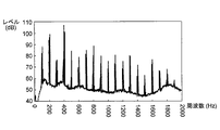
本願発明者らは、この第1の効果を確認すべく、次のような検証を行った。まず、静音化装置1の開口2を騒音源90たる空気ポンプ84に接続し、空気ポンプ84を駆動させている間に開口3から放射された音を収音し、収音した音のパワースペクトルを測定した。また、静音化装置1のものと同寸法で消音器10,20,30,及び40が設けられていない管路4’の一方の開口2’を騒音源90たる空気ポンプ84に接続し、空気ポンプ84を駆動させている間にこの管路4’の他方の開口3’から放射された音のパワースペクトルを測定した。図2は、以上のようにして測定した両パワースペクトルを周波数軸を揃えて示した図である。また、図3は、静音化装置1を接続した場合におけるパワースペクトルを人間の聴覚特性に応じて補正したA特性波形と、管路4’を接続した場合におけるパワースペクトルを人間の聴覚特性に応じて補正したA特性波形とを、周波数軸を揃えて示した図である。騒音源90に静音化装置1を備え付けた場合と管路4を備え付けた場合の各々における各周波数成分の振幅を比較すると、低域から高域までのほぼ全周波数成分において、静音化装置1を備え付けた場合の方が管路4’を備え付けた場合よりも振幅が小さくなっている。また、静音化装置1を備え付けた場合のパワースペクトルでは、管路4’を備え付けた場合のパワースペクトルにおいてピークとなっている周波数成分が十分に小さくなっている。このことから、静音化装置1を騒音源90たる空気ポンプ84に備え付けることにより、確実な静音効果が得られることが分かる。   The inventors of the present application conducted the following verification in order to confirm the first effect. First, the opening 2 of the silencer 1 is connected to the air pump 84 as the noise source 90, and the sound radiated from the opening 3 is collected while the air pump 84 is driven, and the power spectrum of the collected sound is collected. Was measured. Further, one opening 2 ′ of the pipe line 4 ′ having the same size as that of the silencer 1 and not provided with the silencers 10, 20, 30, and 40 is connected to the air pump 84 as the noise source 90, and the air While driving the pump 84, the power spectrum of the sound radiated from the other opening 3 ′ of the pipe line 4 ′ was measured. FIG. 2 is a diagram showing both power spectra measured as described above, with the frequency axes aligned. FIG. 3 shows an A characteristic waveform obtained by correcting the power spectrum in accordance with the human auditory characteristic when the silencer 1 is connected, and the power spectrum in the case of connecting the conduit 4 ′ according to the human auditory characteristic. It is the figure which showed the A characteristic waveform correct | amended by aligning the frequency axis. Comparing the amplitude of each frequency component when the noise reduction device 1 is provided with the noise source 90 and when the pipe line 4 is provided, the noise reduction device 1 is obtained for almost all frequency components from the low range to the high range. The amplitude in the case of being provided is smaller than that in the case of providing the pipe line 4 ′. Further, in the power spectrum when the silencer 1 is provided, the frequency component that is a peak in the power spectrum when the pipe line 4 ′ is provided is sufficiently small. From this, it can be seen that a reliable silencing effect can be obtained by installing the silencing device 1 in the air pump 84 as the noise source 90.

第2に、本実施形態では、共鳴器型消音器10の共鳴周波数を決定付けるパラメータである距離L、共鳴器型消音器20の共鳴周波数を決定づけるパラメータの1つである距離L、及び共鳴器型消音器30の共鳴周波数を決定づけるパラメータの1つである体積Vを調整する手段が設けられている。よって、音波の媒質である空気の温度が変化し、騒音源90から発生する騒音における急峻なピークの周波数が変化している場合でも、距離L、Lや体積Vの調整により、そのピークの周波数成分を低減させることができる。また、騒音源90の静音用の静音化装置1の製造段階において共鳴器10,20,30の設置位置に寸法誤差があった場合でも、距離L及びLや体積Vを調整し、その騒音源90が発生する騒音のピーク周波数の周波数成分を低減させることができる。 Second, in the present embodiment, the distance L 1 that is a parameter that determines the resonance frequency of the resonator-type silencer 10, the distance L 2 that is one of the parameters that determines the resonance frequency of the resonator-type silencer 20, and Means for adjusting the volume V 3 , which is one of the parameters that determine the resonance frequency of the resonator-type silencer 30, is provided. Therefore, even when the temperature of the air, which is the sound wave medium, changes and the frequency of the steep peak in the noise generated from the noise source 90 changes, by adjusting the distances L 1 , L 2 and volume V 3 , Peak frequency components can be reduced. Also, even if there is a dimensional error in the installation position of the resonators 10, 20, 30 in the manufacturing stage of the noise reduction device 1 for silencing of noise source 90, to adjust the distance L 1 and L 2 and volume V 3, The frequency component of the peak frequency of the noise generated by the noise source 90 can be reduced.

第3に、本実施形態では、管路4における開口3よりもλ/4(λ=c/f)だけ開口2側に共鳴器型消音器10が設けられているため、騒音源90から発生する騒音における基本周波数fの周波数成分の減衰量を大きくすることができる。以下、この効果が得られる理由について詳細に説明する。管路4内を開口3に向かって伝搬する音波に周波数fの周波数成分が含まれている場合、その周波数fの音波(進行波)と開口3において反射して逆方向に伝搬される音波(反射波)とが合成され、開口3に節を有する波長λの定在波が発生する。共鳴器型消音器10が開口3よりもλ/4(λ=c/f)だけ開口2側に設けられている場合、共鳴器型消音器10の位置がこの波長λの定在波の腹と一致する。このため、共鳴器型消音器10内の空気がこの波長λの定在波により加振され易くなる。この結果、共鳴器型消音器10を他の位置に設けた場合よりも周波数fの周波数成分の減衰量が大きくなる。また、同様に、本実施形態では、管路4における開口3よりもλ/4(λ=c/f)及びλ/4(λ=c/f)だけ開口2側に共鳴器型消音器20及び30が設けられているため、騒音源90から発生する騒音における周波数f及び周波数fの周波数成分の減衰量を大きくすることができる。 Third, in the present embodiment, lambda 1/4 than the opening 3 (λ 1 = c / f 1) only resonator type silencer 10 to the opening 2 side is provided in line 4, the noise source The amount of attenuation of the frequency component of the fundamental frequency f 1 in the noise generated from 90 can be increased. Hereinafter, the reason why this effect is obtained will be described in detail. If there are frequency components of the frequency f 1 the conduit 4 to the sound wave propagating towards the opening 3, is propagated in the opposite direction is reflected in the sound waves (traveling waves) and opening 3 of the frequency f 1 A sound wave (reflected wave) is combined to generate a standing wave having a wavelength λ 1 having a node in the opening 3. If resonator type silencer 10 is provided only on the opening 2 side λ 1/4 (λ 1 = c / f 1) from the opening 3, the positional resonator type silencer 10 is of the wavelength lambda 1 It coincides with the belly of standing waves. For this reason, the air in the resonator-type silencer 10 is easily vibrated by the standing wave having the wavelength λ 1 . As a result, the attenuation amount of the frequency component of the frequency f 1 becomes larger than when the resonator type silencer 10 is provided at another position. Similarly, in the present embodiment, than the opening 3 in line 4 λ 2/4 (λ 2 = c / f 2) and λ 3/4 (λ 3 = c / f 3) only on the opening 2 side Since the resonator type silencers 20 and 30 are provided, the attenuation amount of the frequency components of the frequency f 2 and the frequency f 3 in the noise generated from the noise source 90 can be increased.

本願発明者らは、この第3の効果を確認すべく、次のような検証を行った。まず、本願発明者らは、周波数f=200Hzの定在波の低減効果が最も高くなる共鳴器の位置が開口3からλ/4(λ=c/f)≒425mmだけ離れた位置であることを確認するための検証を行った。より具体的には、図4(A)に示すように、開管51における一方の開口52から425mmだけ離れた位置に共鳴器型消音器10aを設けた場合、この消音器10aよりも開口52側に共鳴器型消音器10bを設けた場合、この消音器10bの開口52側に共鳴器型消音器10cを設けた場合の各々における挿入損失を測定した。図4(B)は、3つの場合の各々における挿入損失×(−1)で見積もった伝達関数を示す図である。 The inventors of the present application conducted the following verification in order to confirm the third effect. First, the present inventors found that the frequency f 1 = 200 Hz of the standing wave reduction effect of the position of the highest becomes resonator opening 3 from λ 1/4 (λ 1 = c / f 1) separated by ≒ 425 mm Verification was performed to confirm the position. More specifically, as shown in FIG. 4A, when the resonator-type silencer 10a is provided at a position 425 mm away from one opening 52 in the open tube 51, the opening 52 is more than the silencer 10a. When the resonator type silencer 10b was provided on the side, the insertion loss in each case where the resonator type silencer 10c was provided on the opening 52 side of the silencer 10b was measured. FIG. 4B is a diagram showing a transfer function estimated by the insertion loss × (−1) in each of the three cases.

また、本願発明者らは、周波数f=400Hzの定在波の低減効果が最も高くなる消音器の位置が開口3からλ/4(λ=c/f)≒212.5mmだけ離れた位置であることを確認するための検証を行った。より具体的には、図5(A)に示すように、開管51における一方の開口52から212.5mmだけ離れた位置に共鳴器型消音器10dを設けた場合、この消音器10dよりも開口52側に共鳴器型消音器10eを設けた場合、共鳴器10dよりも開口53側に共鳴器型消音器10fを設けた場合の各々における挿入損失を測定した。図5(B)は、3つの場合の各々における挿入損失×(−1)で見積もった伝達関数を示す図である。 Further, the present inventors found that the frequency f 2 = 400 Hz for the standing wave reduction effect becomes highest silencer positions lambda 2/4 from the opening 3 of the (λ 2 = c / f 2 ) ≒ 212.5mm by Verification was performed to confirm that the position was far away. More specifically, as shown in FIG. 5 (A), when a resonator type silencer 10d is provided at a position away from one opening 52 in the open tube 51 by 212.5 mm, it is more than the silencer 10d. When the resonator-type silencer 10e was provided on the opening 52 side, the insertion loss in each case where the resonator-type silencer 10f was provided on the opening 53 side rather than the resonator 10d was measured. FIG. 5B is a diagram illustrating a transfer function estimated by insertion loss × (−1) in each of the three cases.

また、本願発明者らは、周波数f=600Hzの定在波の低減効果が最も高くなる消音器の位置が開口3からλ/4(λ=c/f)≒141mmだけ離れた位置であることを確認するための検証を行った。より具体的には、図6(A)に示すように、開管51における一方の開口52から141mmだけ離れた位置に共鳴器型消音器10gを設けた場合、消音器10gよりも開口52側に共鳴器型消音器10hを設けた場合、消音器10gよりも開口53側に共鳴器型消音器10iを設けた場合、消音器10iよりも開口53側に共鳴器型消音器10jを設けた場合の各々における挿入損失を測定した。図6(B)は、3つの場合の各々における挿入損失×(−1)で見積もった伝達関数を示す図である。 Further, the present inventors found that the frequency f 3 = 600 Hz of the standing wave reduction effect of the position of the highest becomes muffler opening 3 from λ 3/4 (λ 3 = c / f 3) apart ≒ 141 mm Verification was performed to confirm the position. More specifically, as shown in FIG. 6A, when the resonator-type silencer 10g is provided at a position away from one opening 52 in the open tube 51 by 141 mm, the opening 52 side of the silencer 10g is provided. In the case where the resonator type silencer 10h is provided, the resonator type silencer 10j is provided closer to the opening 53 than the silencer 10i when the resonator type silencer 10i is provided closer to the opening 53 than the silencer 10g. The insertion loss in each case was measured. FIG. 6B is a diagram illustrating a transfer function estimated by insertion loss × (−1) in each of the three cases.

図4(B)における200Hzの周波数成分の振幅に着目すると、開口52から425mmだけ離れた位置に共鳴器型消音器10aを設けた場合は、残りの2つ場合に比べて、200Hzの周波数成分の減衰量が大きくなっている。また、図5(B)における400Hzの周波数成分の振幅に着目すると、開口52から212.5mmだけ離れた位置に共鳴器型消音器10dを設けた場合は、残りの2つ場合に比べて、400Hzの周波数成分の減衰量が大きくなっている。図6(B)における600Hzの周波数成分の振幅に着目すると、開口52から141mmだけ離れた位置に共鳴器型消音器10gを設けた場合は、残りの3つの場合に比べて、600Hzの周波数成分の減衰量が大きくなっている。このことから、開口3よりもλ/4,λ/4,及びλ/4だけ開口2側に共鳴器型消音器10,20,及び30を設けた場合に、周波数f,f,及びfの周波数成分の減衰量が最も大きくなることが分かる。 Focusing on the amplitude of the 200 Hz frequency component in FIG. 4B, when the resonator-type silencer 10a is provided at a position 425 mm away from the opening 52, the 200 Hz frequency component is compared to the remaining two cases. The amount of attenuation increases. Also, focusing on the amplitude of the 400 Hz frequency component in FIG. 5B, when the resonator-type silencer 10d is provided at a position away from the opening 52 by 212.5 mm, compared to the remaining two cases, The attenuation amount of the frequency component of 400 Hz is large. Focusing on the amplitude of the 600 Hz frequency component in FIG. 6B, when the resonator-type silencer 10 g is provided at a position away from the opening 52 by 141 mm, the 600 Hz frequency component is compared to the remaining three cases. The amount of attenuation increases. Therefore, when lambda 1/4 from the opening 3, lambda 2/4, and lambda 3/4 by opening 2 side resonator type silencer 10, 20, and 30 is provided, the frequency f 1, f It can be seen that the attenuation amounts of the frequency components of 2 and f 3 are the largest.

以上、この発明の一実施形態について説明したが、この発明には他にも実施形態があり得る。例えば、以下の通りである。
(1)上記実施形態では、共鳴器型消音器10を円筒部11と円筒部12とを連結させたものにより構成した。しかし、共鳴器型消音器10の構成はこれに限らない。例えば、共鳴器型消音器10を次のような構成のものにしてもよい。図7に示すように、第1の変形例である共鳴器型消音器110は、円筒部111と、円筒部112と、円筒部113とから構成される。円筒部111は、管路4の内側から当該管路4を貫いて外側に延在している。円筒部111における管路4の反対側は開放されている。円筒部112は、円筒部111の外周径と同じ内周径を有している。円筒部112は両端が開放されている。円筒部113は、円筒部112の内周径と同じ外周径を有している。円筒部113における一端の側は開放され、他端の側は閉塞されている。この消音器110では、円筒部111における管路4と反対側の一部分が円筒部112内に挿入され、円筒部113における開放された側の端部の一部が円筒部112内に挿入されることにより、円筒部111,112,及び113の内周面を内郭とする閉管が形成される。この消音器110では、円筒部113を円筒部111に近づけたり遠ざける方向に動かすことにより、円筒部113における閉塞された側の端面と管路4と間の距離L110を調整することができる。この距離L110の調整により、消音器110内において音響エネルギーが減衰する周波数成分を周波数fの低周波側または高周波側に変化させることができる。
Although one embodiment of the present invention has been described above, the present invention may have other embodiments. For example, it is as follows.
(1) In the said embodiment, the resonator type silencer 10 was comprised by what connected the cylindrical part 11 and the cylindrical part 12. FIG. However, the configuration of the resonator type silencer 10 is not limited to this. For example, the resonator-type silencer 10 may be configured as follows. As shown in FIG. 7, a resonator-type silencer 110 that is a first modified example includes a cylindrical portion 111, a cylindrical portion 112, and a cylindrical portion 113. The cylindrical portion 111 extends outward from the inside of the pipeline 4 through the pipeline 4. The opposite side of the pipe line 4 in the cylindrical part 111 is open. The cylindrical portion 112 has the same inner peripheral diameter as the outer peripheral diameter of the cylindrical portion 111. The cylindrical portion 112 is open at both ends. The cylindrical portion 113 has the same outer peripheral diameter as the inner peripheral diameter of the cylindrical portion 112. One end side of the cylindrical portion 113 is opened, and the other end side is closed. In the silencer 110, a part of the cylindrical part 111 on the side opposite to the pipe line 4 is inserted into the cylindrical part 112, and a part of the open end of the cylindrical part 113 is inserted into the cylindrical part 112. As a result, a closed tube having the inner peripheral surfaces of the cylindrical portions 111, 112, and 113 as the inner contour is formed. In the silencer 110, the distance L 110 between the closed end surface of the cylindrical portion 113 and the pipe line 4 can be adjusted by moving the cylindrical portion 113 in a direction to approach or move away from the cylindrical portion 111. By adjustment of the distance L 110, frequency components acoustic energy attenuation in the silencer 110 can be changed to the low frequency side or the higher frequency side of the frequency f 1.

図8に示すように、第2の変形例である共鳴器型消音器210は、円筒部211と円柱部212とから構成される。円筒部211は、管路4の内側から当該管路4を貫いて外側に延在している。この円筒部211における管路4と反対側の端部は開放されている。円柱部212は円筒部211の内周径と同じ外周径を有している。この消音器210では、円筒部211の内周と円柱部212の外周にネジ山及びネジ溝が各々設けられている。この消音器210では、ネジ山及びネジ溝の締結により、円筒部211内に円柱部212が嵌合され、円筒部211の内周面と円柱部212の端面213とを内郭とする閉管が形成される。この消音器210では、円筒部211内の円柱部212を円筒部211に対して回転させることにより、円柱部212の端面213と管路4との間の距離L210を調整することができる。この距離L210の調整により、消音器210内において音響エネルギーが減衰する周波数成分を周波数fの低周波側または高周波側に変化させることができる。 As shown in FIG. 8, a resonator type silencer 210 that is a second modified example includes a cylindrical portion 211 and a column portion 212. The cylindrical portion 211 extends outward from the inside of the pipeline 4 through the pipeline 4. The end of the cylindrical portion 211 opposite to the pipe line 4 is open. The column part 212 has the same outer diameter as the inner diameter of the cylindrical part 211. In the silencer 210, a thread and a screw groove are provided on the inner periphery of the cylindrical portion 211 and the outer periphery of the column portion 212, respectively. In the silencer 210, the cylindrical portion 212 is fitted into the cylindrical portion 211 by fastening the screw thread and the thread groove, and a closed tube having the inner peripheral surface of the cylindrical portion 211 and the end surface 213 of the cylindrical portion 212 as an inner shell is formed. It is formed. In the silencer 210, the distance L 210 between the end surface 213 of the column part 212 and the pipe line 4 can be adjusted by rotating the column part 212 in the cylinder part 211 with respect to the cylinder part 211. By adjusting the distance L 210 , the frequency component in which the acoustic energy is attenuated in the silencer 210 can be changed to the low frequency side or the high frequency side of the frequency f 1 .

図9(A)及び図9(B)に示すように、第3の変形例である共鳴器型消音器310は、管路4の内側から当該管路4を貫いて円筒を延在させ、この円筒における管路4と反対側の端部を閉塞したものである。この消音器310の側面311は、可撓性素材を蛇腹状に成形したものである。この消音器310では、管路4と反対側の端面312を管路4から離す方向に動かしたり、管路4に近づける方向に動かしたりすることにより、端面312と管路4との間の距離L310を調整することができる。この距離L310の調整により、消音器310内において音響エネルギーが減衰する周波数成分を周波数fの低周波側または高周波側に変化させることができる。 As shown in FIG. 9A and FIG. 9B, a resonator type silencer 310 as a third modified example extends a cylinder from the inside of the pipe line 4 through the pipe line 4, The end of the cylinder opposite to the pipe line 4 is closed. A side surface 311 of the silencer 310 is formed by forming a flexible material into a bellows shape. In the silencer 310, the distance between the end surface 312 and the pipe line 4 is moved by moving the end surface 312 opposite to the pipe line 4 in a direction away from the pipe line 4 or in a direction approaching the pipe line 4. L 310 can be adjusted. By adjusting the distance L 310 , the frequency component at which the acoustic energy is attenuated in the silencer 310 can be changed to the low frequency side or the high frequency side of the frequency f 1 .

図10に示すように、第4の変形例である共鳴器型消音器410は、円筒部411とピストン部412とから構成される。円筒部411は、管路4の内側から当該管路4を貫いて外側に延在している。ピストン部412は、幅薄の円柱状をなしている。ピストン部412は、円筒部411の内周径と同じ外周径を有している。この消音器410におけるピストン部412は円筒部411内に挿入され、円筒部411の内周面とピストン部412の底面413とにより閉管が形成される。この消音器410では、ピストン部412を管路4に近づけたり管路4から遠ざける方向に動かすことにより、円筒部411内におけるピストン部412の底面413と管路4との間の距離L410を調整することができる。この距離L410の調整により、消音器410内において音響エネルギーが減衰する周波数成分を周波数fの低周波側または高周波側に変化させることができる。 As shown in FIG. 10, a resonator type silencer 410 that is a fourth modified example includes a cylindrical portion 411 and a piston portion 412. The cylindrical portion 411 extends outward from the inside of the pipeline 4 through the pipeline 4. The piston portion 412 has a thin cylindrical shape. The piston part 412 has the same outer peripheral diameter as the inner peripheral diameter of the cylindrical part 411. The piston portion 412 in the silencer 410 is inserted into the cylindrical portion 411, and a closed tube is formed by the inner peripheral surface of the cylindrical portion 411 and the bottom surface 413 of the piston portion 412. In the silencer 410, the distance L 410 between the bottom surface 413 of the piston part 412 and the pipe line 4 in the cylindrical part 411 is moved by moving the piston part 412 closer to the pipe line 4 or away from the pipe line 4. Can be adjusted. By adjusting the distance L 410 , the frequency component at which the acoustic energy is attenuated in the silencer 410 can be changed to the low frequency side or the high frequency side of the frequency f 1 .

図11に示すように、第5の変形例である共鳴器型消音器510は、円筒部511と円筒部512とから構成される。円筒部511は、管路4の内側から当該管路4を貫いて外側に延在している。この円筒部511における管路4と反対側の端部は開放されている。円筒部511は円筒部512の外周径と同じ内周径を有している。この消音器510では、円筒部511の外周と円筒部512の内周にネジ山及びネジ溝が各々設けられている。この消音器510では、ネジ山及びネジ溝の締結により、円筒部512内に円筒部511が嵌合され、円筒部511及び512の内周面を内郭とする閉管が形成される。この消音器510では、円筒部512を円筒部511に対して回転させることにより、円筒部512における閉塞された側の端面513と管路4との間の距離L510を調整することができる。この距離L510の調整により、消音器510内において音響エネルギーが減衰する周波数成分を周波数fの低周波側または高周波側に変化させることができる。 As shown in FIG. 11, a resonator-type silencer 510 that is a fifth modified example includes a cylindrical portion 511 and a cylindrical portion 512. The cylindrical portion 511 extends from the inside of the pipeline 4 to the outside through the pipeline 4. The end of the cylindrical portion 511 opposite to the pipe line 4 is open. The cylindrical portion 511 has the same inner peripheral diameter as the outer peripheral diameter of the cylindrical portion 512. In the silencer 510, a screw thread and a screw groove are respectively provided on the outer periphery of the cylindrical portion 511 and the inner periphery of the cylindrical portion 512. In the silencer 510, the threaded portion and the thread groove are fastened so that the cylindrical portion 511 is fitted into the cylindrical portion 512, and a closed tube is formed with the inner peripheral surfaces of the cylindrical portions 511 and 512 as an outline. In the silencer 510, the distance L 510 between the closed end surface 513 of the cylindrical portion 512 and the pipe line 4 can be adjusted by rotating the cylindrical portion 512 relative to the cylindrical portion 511. By adjusting the distance L 510 , the frequency component at which the acoustic energy is attenuated in the silencer 510 can be changed to the low frequency side or the high frequency side of the frequency f 1 .

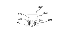
(2)上記実施形態では、共鳴器型消音器20を円筒部21と壺状部23とを連結したものにより構成し、共鳴器型消音器30を、円筒部31、シリンダ部32、及びピストン部33を連結したものにより構成した。しかし、共鳴器型消音器20及び30の構成はこれに限らない。例えば、共鳴器型消音器20及び30の両方または一方(たとえば、共鳴器型消音器20とする)を次のような構成のものにしてもよい。図12に示すように、第6の変形例である共鳴器型消音器220は、円筒部221と、円筒部221の外周径と同じ内周径のネック222を持った壺状部223におけるネック222とを連結させたものである。この消音器220における円筒部221の内周と壺状部223のネック222の外周にはネジ山及びネジ溝が各々設けられている。この消音器220では、ネジ山及びネジ溝の締結により、円筒部221内に壺状部223のネック222が嵌合され、円筒部221及び壺状部223の内周面を内郭とするヘルムホルツ共鳴器が形成される。そして、壺状部223を円筒部221に対して回転させることにより、壺状部223におけるネック222とその奥の空洞224との境界面と管路4との距離L220を調整することができる。この距離L220の調整により、消音器220内において音響エネルギーが減衰する周波数成分を周波数fの低周波側または高周波側に変化させることができる。 (2) In the above embodiment, the resonator-type silencer 20 is configured by connecting the cylindrical portion 21 and the bowl-shaped portion 23, and the resonator-type silencer 30 includes the cylindrical portion 31, the cylinder portion 32, and the piston. The portion 33 is connected. However, the configuration of the resonator type silencers 20 and 30 is not limited to this. For example, both or one of the resonator-type silencers 20 and 30 (for example, the resonator-type silencer 20) may be configured as follows. As shown in FIG. 12, a resonator-type silencer 220 according to a sixth modified example includes a cylindrical portion 221 and a neck in a bowl-shaped portion 223 having a neck 222 having the same inner peripheral diameter as the outer peripheral diameter of the cylindrical portion 221. 222 is connected. In the silencer 220, a thread and a groove are provided on the inner periphery of the cylindrical portion 221 and the outer periphery of the neck 222 of the bowl-shaped portion 223. In the silencer 220, the neck 222 of the hook-like part 223 is fitted into the cylindrical part 221 by fastening the screw thread and the screw groove, and the inner periphery of the cylindrical part 221 and the hook-like part 223 is the Helmholtz. A resonator is formed. Then, by rotating the hook-shaped portion 223 with respect to the cylindrical portion 221, the distance L 220 between the boundary surface between the neck 222 and the inner cavity 224 in the hook-shaped portion 223 and the pipe line 4 can be adjusted. . By adjustment of the distance L 220, frequency components acoustic energy attenuation in the silencer 220 can be changed to the low frequency side or the higher frequency side of the frequency f 2.

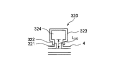
図13に示すように、第7の変形例である共鳴器型消音器320は、円筒部321と、円筒部321の外周径と同じ内周径のネック322を持った壺状部323とから構成される。この消音器320では、円筒部321における管路4の反対側の一部分が壺状部323のネック322内に挿入され、円筒部321及び壺状部323の内周面を内郭とするヘルムホルツ共鳴器が形成される。この消音器320では、壺状部323を管路4に対して近づけたり管路4から遠ざける方向に動かすことにより、壺状部323におけるネック322及びその奥の空洞324間の境界面と管路4と間の距離L320を調整することができる。この距離L320の調整により、消音器320内において音響エネルギーが減衰する周波数成分を周波数fの低周波側または高周波側に変化させることができる。 As shown in FIG. 13, a resonator type silencer 320 as a seventh modified example includes a cylindrical portion 321 and a bowl-shaped portion 323 having a neck 322 having the same inner peripheral diameter as the outer peripheral diameter of the cylindrical portion 321. Composed. In the silencer 320, a part of the cylindrical portion 321 opposite to the pipe line 4 is inserted into the neck 322 of the bowl-shaped portion 323, and the Helmholtz resonance has the inner peripheral surfaces of the cylindrical portion 321 and the bowl-shaped portion 323 as an inner wall. A vessel is formed. In the silencer 320, by moving the hook-shaped part 323 toward the pipe 4 or away from the pipe 4, the boundary surface between the neck 322 and the inner cavity 324 in the hook-shaped part 323 and the pipe line are connected. it is possible to adjust the 4 and the distance L 320 between. By adjustment of the distance L 320, frequency components acoustic energy attenuation in the silencer 320 can be changed to the low frequency side or the higher frequency side of the frequency f 2.

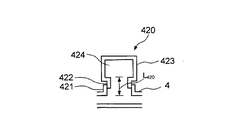
図14に示すように、第8の変形例である共鳴器型消音器420は、円筒部421と、円筒部421の外周径と同じ内周径のネック422を持った壺状部423とから構成される。この消音器420では、壺状部423のネック422の一部分が円筒部421内に挿入され、円筒部421及び壺状部423の内周面を内郭とするヘルムホルツ共鳴器が形成される。この消音器420では、壺状部423を管路4に対して近づけたり管路4から遠ざける方向に動かすことにより、壺状部423におけるネック422とその奥の空洞424との境界面と管路4と間の距離L420を調整することができる。この距離L420の調整により、消音器420内において音響エネルギーが減衰する周波数成分を周波数fの低周波側または高周波側に変化させることができる。 As shown in FIG. 14, a resonator type silencer 420 as an eighth modification includes a cylindrical portion 421 and a bowl-shaped portion 423 having a neck 422 having the same inner peripheral diameter as the outer peripheral diameter of the cylindrical portion 421. Composed. In the silencer 420, a part of the neck 422 of the bowl-shaped part 423 is inserted into the cylindrical part 421, thereby forming a Helmholtz resonator having the inner peripheral surfaces of the cylindrical part 421 and the bowl-shaped part 423 as an inner contour. In the silencer 420, by moving the hook-shaped portion 423 toward or away from the pipe line 4, the boundary surface between the neck 422 in the hook-shaped part 423 and the cavity 424 at the back thereof and the pipe line it is possible to adjust the 4 and the distance L 420 between. By adjusting the distance L 420 , the frequency component in which the acoustic energy is attenuated in the silencer 420 can be changed to the low frequency side or the high frequency side of the frequency f 2 .

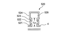
図15に示すように、第9の変形例である共鳴器型消音器520は、円筒部521と、円筒部522と、円筒部522の外周径と同じ内周径のネック523を持った壺状部524とから構成される。この消音器520では、円筒部521における管路4の反対側の一部分と、壺状部524におけるネック523の一部分が円筒部522の両側から円筒部522内に挿入され、円筒部521,522及び壺状部524の内周面を内郭とするヘルムホルツ共鳴器が形成される。この消音器520では、壺状部524を円筒部521に近づけたり遠ざける方向に動かすことにより、壺状部524におけるネック522とその奥の空洞528との境界面と管路4と間の距離L520を調整することができる。この距離L520の調整により、消音器520内において音響エネルギーが減衰する周波数成分を周波数fの低周波側または高周波側に変化させることができる。 As shown in FIG. 15, a resonator type silencer 520 as a ninth modified example has a cylindrical portion 521, a cylindrical portion 522, and a neck 523 having the same inner peripheral diameter as the outer peripheral diameter of the cylindrical portion 522. And a shape portion 524. In the silencer 520, a part of the cylindrical part 521 opposite to the pipe line 4 and a part of the neck 523 of the flange-like part 524 are inserted into the cylindrical part 522 from both sides of the cylindrical part 522, and the cylindrical parts 521, 522 and A Helmholtz resonator having the inner peripheral surface of the bowl-shaped portion 524 as an outline is formed. In the silencer 520, the distance L between the boundary surface of the neck 522 and the cavity 528 at the back of the flange 524 and the pipe line 4 is moved by moving the flange 524 closer to or away from the cylindrical portion 521. 520 can be adjusted. By adjustment of the distance L 520, frequency components acoustic energy attenuation in the silencer 520 can be changed to the low frequency side or the higher frequency side of the frequency f 2.

図16(A)及び図16(B)に示すように、第10の変形例である共鳴器型消音器620は、管路4と連通するネック621を有する壺状をなしている。この消音器620におけるネック621は、可撓性素材を蛇腹状に成形したものである。この消音器620では、当該消音器620を管路4から離す方向に引いたり、管路4に近づける方向に押したりすることにより、ネック621とその奥の空洞622との境界面と管路4と間の距離L620を調整することができる。この距離L620の調整により、消音器620内において音響エネルギーが減衰する周波数成分を周波数fの低周波側または高周波側に変化させることができる。 As shown in FIGS. 16A and 16B, the resonator type silencer 620 as the tenth modification has a bowl shape having a neck 621 communicating with the pipe line 4. The neck 621 in the silencer 620 is formed by forming a flexible material into a bellows shape. In the silencer 620, the silencer 620 is pulled in a direction away from the pipeline 4 or pushed in a direction closer to the pipeline 4, whereby the boundary surface between the neck 621 and the inner cavity 622 and the pipeline 4. The distance L 620 between can be adjusted. By adjusting the distance L 620 , the frequency component at which the acoustic energy is attenuated in the silencer 620 can be changed to the low frequency side or the high frequency side of the frequency f 2 .

図17に示すように、第11の変形例である共鳴器型消音器720は、管路4と連通するネック721を有する壺状をなしている。この消音器720におけるネック721の奥の空洞722には体積調整部材723が挿入される。体積調整部材723は、空洞722の内周径と同じ外周径を持った円柱状をなしている。この体積調整部材723における一端面の中心と他端面の中心との間には、ネック721の内周と同じ直径を持った孔724が穿設されている。ここで、空洞722内における体積調整部材723の体積が大きい程、空洞722における体積調整部材723を除いた部分の体積は小さくなる。この消音器720では、空洞722内に挿入されている体積調整部材723を体積のより大きなものや小さなものに置き換えることにより、空洞722における体積調整部材723を除いた部分の体積V720を調整することができる。この体積V720の調整により、消音器720内において音響エネルギーが減衰する周波数成分を周波数fの低周波側または高周波側に変化させることができる。 As shown in FIG. 17, the resonator type silencer 720 according to the eleventh modification has a bowl shape having a neck 721 communicating with the pipe line 4. A volume adjusting member 723 is inserted into a cavity 722 at the back of the neck 721 in the silencer 720. The volume adjusting member 723 has a cylindrical shape having the same outer diameter as the inner diameter of the cavity 722. A hole 724 having the same diameter as the inner periphery of the neck 721 is formed between the center of one end surface and the center of the other end surface of the volume adjusting member 723. Here, the larger the volume of the volume adjusting member 723 in the cavity 722, the smaller the volume of the cavity 722 excluding the volume adjusting member 723. In the silencer 720, the volume adjustment member 723 inserted in the cavity 722 is replaced with a larger or smaller volume adjustment member, thereby adjusting the volume V 720 of the cavity 722 excluding the volume adjustment member 723. be able to. By adjusting the volume V 720 , the frequency component in which the acoustic energy is attenuated in the silencer 720 can be changed to the low frequency side or the high frequency side of the frequency f 2 .

図18に示すように、第12の変形例である共鳴器型消音器820は、管路4内と連通する碗部821と、この碗部821とともに空洞822を形成する円筒部823とから構成される。この消音器820における碗部821は、管路4内から当該管路4を貫いて外側に延在する小径の円筒の先端に大径の円筒を連結したものである。円筒部823は、碗部821における大径の円筒の部分の内周径と同じ外周径を有している。碗部821の大径の円筒の部分は開放されている。円筒部823における一方の端部は閉塞されており、他方の端部は開放されている。この消音器820では、円筒部823がその開放された側の端面を碗部821に向けて碗部821内に挿入され、碗部821及び円筒部823の内周面を内郭とするヘルムホルツ共鳴器が形成される。この消音器820では、円筒部823を管路4に対して近づけたり管路4から遠ざける方向に動かすことにより、空洞822の体積V820を調整することができる。この体積V820の調整により、消音器820内において音響エネルギーが減衰する周波数成分を周波数fの低周波側または高周波側に変化させることができる。 As shown in FIG. 18, a resonator type silencer 820 as a twelfth modified example includes a flange portion 821 communicating with the inside of the duct 4 and a cylindrical portion 823 that forms a cavity 822 together with the flange portion 821. Is done. The flange 821 in the silencer 820 is obtained by connecting a large-diameter cylinder to the tip of a small-diameter cylinder that extends from the inside of the duct 4 through the duct 4 to the outside. The cylindrical portion 823 has the same outer peripheral diameter as the inner peripheral diameter of the large-diameter cylindrical portion in the collar portion 821. The large-diameter cylindrical portion of the collar portion 821 is open. One end of the cylindrical portion 823 is closed, and the other end is open. In the silencer 820, the cylindrical part 823 is inserted into the collar part 821 with the open end face thereof facing the collar part 821, and Helmholtz resonance with the inner peripheral surfaces of the collar part 821 and the cylindrical part 823 as the inner shell. A vessel is formed. In the silencer 820, the volume V 820 of the cavity 822 can be adjusted by moving the cylindrical portion 823 closer to or away from the pipeline 4. By adjusting the volume V 820 , the frequency component in which the acoustic energy is attenuated in the silencer 820 can be changed to the low frequency side or the high frequency side of the frequency f 2 .

図19に示すように、第13の変形例である共鳴器型消音器920は、管路4内と連通する碗部921と、この碗部921とともに空洞922を形成する円筒部923とから構成される。この消音器920では、碗部921における大径の円筒の部分がその開放された側の面を円筒部923に向けて円筒部923内に挿入され、碗部921及び円筒部923の内周面を内郭とするヘルムホルツ共鳴器が形成される。この消音器920では、円筒部923を管路4に対して近づけたり管路4から遠ざける方向に動かすことにより、空洞922の体積V920を調整することができる。この体積V920の調整により、消音器920内において音響エネルギーが減衰する周波数成分を周波数fの低周波側または高周波側に変化させることができる。 As shown in FIG. 19, a resonator type silencer 920 that is a thirteenth modification includes a flange portion 921 that communicates with the inside of the duct 4 and a cylindrical portion 923 that forms a cavity 922 together with the flange portion 921. Is done. In the silencer 920, the large-diameter cylindrical portion of the flange portion 921 is inserted into the cylindrical portion 923 with the open-side surface facing the cylindrical portion 923, and the inner peripheral surfaces of the flange portion 921 and the cylindrical portion 923. A Helmholtz resonator is formed. In the silencer 920, the volume V 920 of the cavity 922 can be adjusted by moving the cylindrical portion 923 closer to the pipeline 4 or away from the pipeline 4. By adjustment of the volume V 920, the frequency components acoustic energy attenuation in the silencer 920 can be changed to the low frequency side or the higher frequency side of the frequency f 2.

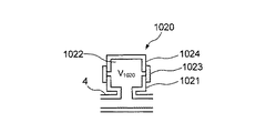
図20に示すように、第14の変形例である共鳴器型消音器1020は、管路4内と連通する碗部1021と、この碗部1021とともに空洞1022を形成する円筒部1023及び1024とから構成される。この消音器1020では、碗部1021における大径の円筒の部分がその開放された側の面を円筒部1023に向けて円筒部1023内に挿入されるとともに、円筒部1024がその開放された側の面を円筒部1023に向けて円筒部1023内に挿入され、碗部1021と円筒部1023及び1024の内周面を内郭とするヘルムホルツ共鳴器が形成される。この消音器1020では、円筒部1024を管路4に対して近づけたり管路4から遠ざける方向に動かすことにより、空洞1022の体積V1020を調整することができる。この体積V1020の調整により、消音器1020内において音響エネルギーが減衰する周波数成分を周波数fの低周波側または高周波側に変化させることができる。 As shown in FIG. 20, a resonator type silencer 1020 according to a fourteenth modification includes a flange portion 1021 that communicates with the inside of the duct 4, and cylindrical portions 1023 and 1024 that form a cavity 1022 together with the flange portion 1021. Consists of In the silencer 1020, the large-diameter cylindrical portion of the flange portion 1021 is inserted into the cylindrical portion 1023 with the open side surface facing the cylindrical portion 1023, and the cylindrical portion 1024 is open on the open side. The Helmholtz resonator is formed with the inner surface of the flange 1021 and the cylindrical portions 1023 and 1024 as the inner shell. In the silencer 1020, the volume V 1020 of the cavity 1022 can be adjusted by moving the cylindrical portion 1024 toward or away from the pipeline 4. By adjustment of the volume V 1020, a frequency component is an acoustic energy attenuation in the silencer 1020 can be changed to the low frequency side or the higher frequency side of the frequency f 2.

図21に示すように、第15の変形例である共鳴器型消音器1120では、管路4内と連通する碗部1121と、この碗部1121とともに空洞1122を形成する円筒部1123とから構成される。この消音器1120の碗部1121における大径の円筒の部分の内周と円筒部1123の外周には、ネジ山及びネジ溝が各々設けられている。この消音器1120では、ネジ山及びネジ溝の締結により、碗部1121における大径の円筒の部分内に円筒部1123が嵌合され、碗部1121及び円筒部1123の内周面を内郭とするヘルムホルツ共鳴器が形成される。この消音器1120では、円筒部1123を碗部1121に対して回転させ、円筒部1123を碗部1121に対して接離する方向に移動させることにより、空洞1122の体積V1120を調整することができる。この体積V1120の調整により、消音器1120内において音響エネルギーが減衰する周波数成分を周波数fの低周波側または高周波側に変化させることができる。 As shown in FIG. 21, a resonator-type silencer 1120 according to the fifteenth modified example includes a flange portion 1121 that communicates with the inside of the conduit 4 and a cylindrical portion 1123 that forms a cavity 1122 together with the flange portion 1121. Is done. On the inner periphery of the large-diameter cylindrical portion in the flange portion 1121 of the silencer 1120 and the outer periphery of the cylindrical portion 1123, a screw thread and a screw groove are respectively provided. In the silencer 1120, the threaded portion and the thread groove are fastened so that the cylindrical portion 1123 is fitted into the large-diameter cylindrical portion of the flange portion 1121, and the inner peripheral surfaces of the flange portion 1121 and the cylindrical portion 1123 are defined as inner walls. A Helmholtz resonator is formed. In the silencer 1120, the volume V 1120 of the cavity 1122 can be adjusted by rotating the cylindrical portion 1123 with respect to the flange portion 1121 and moving the cylindrical portion 1123 in a direction in which the cylindrical portion 1123 contacts and separates from the flange portion 1121. it can. By adjusting the volume V 1120 , the frequency component at which the acoustic energy is attenuated in the silencer 1120 can be changed to the low frequency side or the high frequency side of the frequency f 2 .

図22に示すように、第16の変形例である共鳴器型消音器1220は、管路4内と連通する碗部1221、この碗部1221とともに空洞1222を形成する円筒部1223とから構成される。この消音器1220の碗部1221における大径の円筒の部分の外周と円筒部1223の内周には、ネジ山及びネジ溝が各々設けられている。この消音器1220では、ネジ山及びネジ溝の締結により、碗部1221における大径の円筒の部分が円筒部1223内に嵌合され、碗部1221及び円筒部1223の内周面を内郭とするヘルムホルツ共鳴器が形成される。この消音器1220では、円筒部1223を碗部1221に対して回転させ、円筒部1223を碗部1221に対して接離する方向に移動させることにより、空洞1222の体積V1220を調整することができる。この体積V1220の調整により、消音器1220内において音響エネルギーが減衰する周波数成分を周波数fの低周波側または高周波側に変化させることができる。 As shown in FIG. 22, the resonator type silencer 1220 according to the sixteenth modified example includes a flange portion 1221 that communicates with the inside of the duct 4 and a cylindrical portion 1223 that forms a cavity 1222 together with the flange portion 1221. The On the outer periphery of the large-diameter cylindrical portion of the flange 1221 of the silencer 1220 and the inner periphery of the cylindrical portion 1223, a screw thread and a screw groove are respectively provided. In the silencer 1220, a large-diameter cylindrical portion of the flange portion 1221 is fitted into the cylindrical portion 1223 by fastening the screw thread and the screw groove, and the inner peripheral surfaces of the flange portion 1221 and the cylindrical portion 1223 are defined as inner walls. A Helmholtz resonator is formed. In the silencer 1220, the volume V 1220 of the cavity 1222 can be adjusted by rotating the cylindrical portion 1223 relative to the flange portion 1221 and moving the cylindrical portion 1223 toward and away from the flange portion 1221. it can. By adjustment of the volume V 1220, a frequency component is an acoustic energy attenuation in the silencer 1220 can be changed to the low frequency side or the higher frequency side of the frequency f 2.

図23に示すように、第17の変形例である共鳴器型消音器1320は、管路4内と連通する碗部1321と、この碗部1321とともに空洞1322を形成する円柱部1323とから構成される。碗部1321は、管路4内から当該管路4を貫いて外側に延在する小径の円筒に大径の円筒を連結したものである。円柱部1323は、碗部1321における大径の円筒の内周径と同じ外周径を有している。碗部1321の大径の円筒は開放されている。この消音器1320の碗部1321における大径の円筒の内周と円柱部1321の外周には、ネジ山及びネジ溝が各々設けられている。この消音器1320では、ネジ山及びネジ溝の締結により、碗部1321における大径の円筒内に円柱部1323が嵌合され、碗部1321及び円柱部1323の内周面を内郭とするヘルムホルツ共鳴器が形成される。この消音器1320では、円柱部1323を碗部1321に対して回転させ、円柱部1323を碗部1321に対して接離する方向に移動させることにより、空洞1322の体積V1320を調整することができる。この体積V1320の調整により、消音器1320内において音響エネルギーを減衰する周波数成分を周波数fの低周波側または高周波側に変化させることができる。 As shown in FIG. 23, a resonator type silencer 1320 which is a seventeenth modification includes a flange portion 1321 communicating with the inside of the conduit 4 and a cylindrical portion 1323 which forms a cavity 1322 together with the flange portion 1321. Is done. The flange 1321 is formed by connecting a large-diameter cylinder to a small-diameter cylinder that extends from the inside of the pipeline 4 through the pipeline 4 to the outside. The column portion 1323 has the same outer diameter as the inner diameter of the large-diameter cylinder in the flange portion 1321. The large-diameter cylinder of the flange 1321 is open. On the inner periphery of the large-diameter cylinder and the outer periphery of the columnar portion 1321 in the flange portion 1321 of the silencer 1320, a screw thread and a screw groove are respectively provided. In this silencer 1320, by fastening a screw thread and a thread groove, a columnar portion 1323 is fitted into a large-diameter cylinder in the flange portion 1321, and the Helmholtz with the inner peripheral surfaces of the flange portion 1321 and the columnar portion 1323 as an inner shell. A resonator is formed. In the silencer 1320, the volume V 1320 of the cavity 1322 can be adjusted by rotating the column portion 1323 relative to the flange portion 1321 and moving the column portion 1323 toward and away from the flange portion 1321. it can. By adjustment of the volume V 1320, a frequency component that attenuates the acoustic energy in the muffler 1320 can be changed to the low frequency side or the higher frequency side of the frequency f 2.

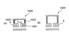
図24(A)及び図24(B)に示すように、第18の変形例である共鳴器型消音器1420は、管路4内と連通するネック1421を持った壺状をなしている。この消音器1420におけるネック1421の奥の空洞1422を覆う側面1423は、可撓性素材を蛇腹状に成形したものである。この消音器1420では、当該消音器1420を管路4から離す方向に引いたり、管路4に近づける方向に押したりすることにより、空洞1422の体積V1420を調整することができる。この体積V1420の調整により、消音器1420内において音響エネルギーが減衰する周波数成分を周波数fの低周波側または高周波側に変化させることができる。 As shown in FIGS. 24A and 24B, the resonator-type silencer 1420 which is the eighteenth modified example has a bowl shape having a neck 1421 communicating with the inside of the pipe 4. A side surface 1423 covering the cavity 1422 at the back of the neck 1421 in the silencer 1420 is formed by forming a flexible material into a bellows shape. In the silencer 1420, the volume V 1420 of the cavity 1422 can be adjusted by pulling the silencer 1420 away from the pipe line 4 or pushing it in a direction approaching the pipe line 4. By adjustment of the volume V 1420, a frequency component is an acoustic energy attenuation in the silencer 1420 can be changed to the low frequency side or the higher frequency side of the frequency f 2.

図25に示すように、第19の変形例である共鳴器型消音器1520は、管路4内と連通するネック1521を有する壺状をなしている。この消音器1520におけるネック1521の奥の空洞1522には内挿材1523が挿入される。内挿材1523は、例えば、砂や粘土である。空洞1522内における内挿材1523の体積が大きいほど、空洞1522内における内挿材1523を除いた部分の体積V1520は小さくなる。この消音器1520では、空洞1522内に挿入されている内挿材1523を体積のより大きなものや小さなものに置き換えることにより、体積V1520を調整することができる。この体積V1520の調整により、消音器1520内において音響エネルギーが減衰する周波数成分を周波数fの低周波側または高周波側に変化させることができる。 As shown in FIG. 25, the resonator type silencer 1520 as the nineteenth modification has a bowl shape having a neck 1521 communicating with the inside of the pipe line 4. An insert 1523 is inserted into a cavity 1522 at the back of the neck 1521 in the silencer 1520. The insertion material 1523 is, for example, sand or clay. As the volume of the insert 1523 in the cavity 1522 increases, the volume V 1520 of the portion excluding the insert 1523 in the cavity 1522 decreases. In the silencer 1520, the volume V 1520 can be adjusted by replacing the insertion material 1523 inserted into the cavity 1522 with a larger or smaller volume. By adjusting the volume V 1520 , the frequency component in which the acoustic energy is attenuated in the silencer 1520 can be changed to the low frequency side or the high frequency side of the frequency f 2 .

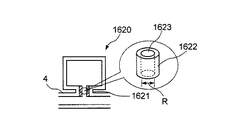
図26に示すように、第20の変形例である共鳴器型消音器1620は、管路4内と連通するネック1621を持った壺状をなしている。消音器1620では、ネック1621にネック径調整部材1622が挿入される。このネック径調整部材1622は、ネック1621の内周径とほぼ同じ外周径を持った円柱状をなしている。ネック径調整部材1622における一端面の中心と他端面の中心との間には、孔1623が穿設されている。この消音器1620では、ネック1621に挿入されているネック径調整部材1622を孔1623の直径がより大きいものや小さいものに置き換えることにより、ヘルムホルツ共鳴周波数を決定づけるパラメータの1つである開口端補正値を変化させることができる。よって、ネック1621に挿入されているネック径調整部材1622を孔1623の直径がより大きいものや小さいものに置き換えることにより、消音器1620内において音響エネルギーが減衰する周波数成分を周波数fの低周波側または高周波側に変化させることができる。 As shown in FIG. 26, the resonator type silencer 1620 which is the twentieth modification has a bowl shape having a neck 1621 communicating with the inside of the pipe line 4. In the silencer 1620, a neck diameter adjusting member 1622 is inserted into the neck 1621. The neck diameter adjusting member 1622 has a cylindrical shape having an outer peripheral diameter substantially the same as the inner peripheral diameter of the neck 1621. A hole 1623 is formed between the center of one end surface and the center of the other end surface of the neck diameter adjusting member 1622. In the silencer 1620, the opening end correction value which is one of the parameters determining the Helmholtz resonance frequency is obtained by replacing the neck diameter adjusting member 1622 inserted into the neck 1621 with one having a larger or smaller diameter of the hole 1623. Can be changed. Therefore, by replacing the neck diameter adjusting member 1622 inserted into the neck 1621 with one having a larger or smaller diameter of the hole 1623, the frequency component in which the acoustic energy is attenuated in the silencer 1620 is reduced to the low frequency f 2 . Side or high frequency side.

(3)上記実施形態において、空気ポンプ84内のモータの回転数を検出する検出手段と、共鳴器型消音器10,20,30の共鳴周波数を決定づけるパラメータとなる寸法を検出手段が検知した回転数に応じて変化させる制御手段とを設けてもよい。また、空気ポンプ84から発生する騒音を収音する収音手段と、共鳴器型消音器10,20,30の共鳴周波数を決定づけるパラメータとなる寸法を収音手段が検知した回転数に応じて変化させる制御手段とを設けてもよい。 (3) In the above embodiment, the detection means for detecting the rotational speed of the motor in the air pump 84 and the rotation detected by the detection means for the dimensions that determine the resonance frequency of the resonator type silencers 10, 20, and 30. Control means for changing according to the number may be provided. The sound collecting means for picking up the noise generated from the air pump 84 and the dimensions that determine the resonance frequency of the resonator type silencers 10, 20, and 30 change according to the rotational speed detected by the sound collecting means. And a control means to be provided.

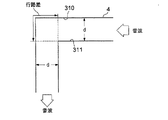
(4)上記実施形態では、管路4は断面積が一定で一直線状をなしていた。しかし、管路4において開口2から孔42の間は任意の断面積であってもよいし、任意に屈曲していてもよい。また、管路4における開口2から孔42の間は任意に枝分かれしていてもよい。つまり、開口2から孔42の間は自由に設計できる。また、管路4における孔43から開口3の間は、静音化の対象となる音波の波長λと管路4の断面積dとに依存して決まる影響が軽微なものである場合は、管路4を屈曲させて全体のコンパクト化を図ってもよい。より具体的には、図27に示すように、管路4内における屈曲方向を向いた面310の近傍を通る音波の行路とその反対側の面311の近傍を通る音波の行路の行路差が音波の波長λよりも十分に小さい場合には、当該管路4を屈曲させることよる影響は無視できるほど小さい。よって、この場合、管路4を屈曲させてもよい。 (4) In the above embodiment, the pipe line 4 has a constant cross-sectional area and is linear. However, the pipe 4 may have an arbitrary cross-sectional area between the opening 2 and the hole 42 or may be arbitrarily bent. Further, the branch 4 may be arbitrarily branched from the opening 2 to the hole 42. That is, the space between the opening 2 and the hole 42 can be designed freely. In addition, between the hole 43 and the opening 3 in the pipe line 4, if the influence determined depending on the wavelength λ of the sound wave to be silenced and the cross-sectional area d of the pipe line 4 is slight, The path 4 may be bent to make the whole compact. More specifically, as shown in FIG. 27, the path difference between the path of the sound wave passing through the vicinity of the surface 310 facing the bending direction in the conduit 4 and the path of the sound wave passing through the vicinity of the opposite surface 311 is When it is sufficiently smaller than the wavelength λ of the sound wave, the influence of bending the pipe line 4 is negligibly small. Therefore, in this case, the conduit 4 may be bent.

(5)上記実施形態において、図28に示す静音化装置1Aのように、管路4に当該管路4の管路長を調整する一又は複数の管路長調整手段95(例えば、蛇腹、シリンダー、ゴム、ネジ込み、継手など:図28の例では管路長調整手段95の個数は3つ)を設けてもよい。この静音化装置10Aによると、管路4における共鳴器型消音器10,20,及び30の位置と管路4内の定在波の音圧が最も高くなる位置が一致するように開口3と共鳴器型消音器10,20,及び30との距離を調整し、消音効果をより高めることができる(第1の効果)。 (5) In the above embodiment, as in the silencer 1A shown in FIG. 28, one or a plurality of pipe length adjusting means 95 (for example, bellows, etc.) for adjusting the pipe length of the pipe 4 to the pipe 4 Cylinder, rubber, screw-in, joint, etc .: In the example of FIG. 28, the number of pipe length adjusting means 95 may be three). According to the silencer 10 </ b> A, the position of the resonator-type silencers 10, 20, and 30 in the pipe line 4 and the opening 3 are set so that the position where the sound pressure of the standing wave in the pipe line 4 becomes the highest. The distance from the resonator type silencers 10, 20, and 30 can be adjusted to further enhance the silencing effect (first effect).

また、この静音化装置10Aによると、当該静音化装置10Aにおける騒音源90に塞がれた開口2からその反対側の開口3に至る全区間の透過損失×(−1)で見積もった伝達関数のピークの周波数と騒音源90から発生する線スペクトルの周波数とが一致した場合にはその周波数と共鳴器型消音器10,20,30の共鳴周波数を一致させたとしても充分な消音効果が得られない、という問題を改善することができる(第2の効果)。   Further, according to the silencer 10A, the transfer function estimated by transmission loss × (−1) of the entire section from the opening 2 blocked by the noise source 90 in the silencer 10A to the opening 3 on the opposite side. If the frequency of the peak and the frequency of the line spectrum generated from the noise source 90 coincide with each other, a sufficient silencing effect can be obtained even if the frequency and the resonance frequency of the resonator type silencer 10, 20, 30 are matched. Can be improved (second effect).

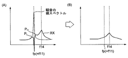
以下、この第2の効果について、詳細に説明する。静音化装置1は、管路4に膨張型消音器40と3つの共鳴器型消音器10,20,及び30を設けたものであるから、消音化装置1における騒音源90に塞がれた開口2からその反対側の開口3に至る全区間の透過損失×(−1)で見積もった伝達関数R10は、管路4に共鳴器型消音器10のみを設けたものの透過損失×(−1)で見積もった伝達関数R11と、管路4に共鳴器型消音器20のみを設けたものの透過損失×(−1)で見積もった伝達関数R12と、管路4に共鳴器型消音器30のみを設けたものの透過損失×(−1)で見積もった伝達関数R13と、管路4に膨張側消音器40のみを設けたものの透過損失×(−1)で見積もった伝達関数R14の影響を含むものと考えることができる。図29(A)に示すように、伝達関数R11は、各消音器10の寸法に依存する周波数f11に急峻なディップを持ったものとなる(R12,R13は同等であるので以後説明を省く)。一方、伝達関数R14は、ピークを複数持ったものとなる(図36(B)参照)。そして、前述した通り、伝達関数R14に現れるピークの周波数は、膨張側消音器40の膨張部内の空洞の断面積や膨張部の両端に繋がる各管路4の形状(管路4の断面積、管路4の屈曲の有無、管路4の枝分かれの有無、継手などの介在の有無など)や長さなどの様々な条件に依存するため、騒音源90に接続して実際に利用してみるまで伝達関数R14のどの周波数(f14)にピークが発生するかは予測が困難である。このため、図29(B)に示すように、騒音源90から発生した騒音における周波数fpと伝達関数R14の周波数f14が一致することにより充分消音できなくなる場合がある。   Hereinafter, the second effect will be described in detail. Since the silencer 1 is provided with the expansion silencer 40 and the three resonator silencers 10, 20, and 30 in the pipeline 4, the noise source 90 in the silencer 1 is blocked. The transfer function R10 estimated by the transmission loss of the entire section from the opening 2 to the opening 3 on the opposite side × (−1) is the transmission loss of the case where only the resonator-type silencer 10 is provided in the pipeline 4 × (−1. ), Transfer function R12 estimated by transmission loss x (-1) of the case where only the resonator type silencer 20 is provided in the pipe line 4, and only the resonator type silencer 30 in the pipe line 4. The transmission function R13 estimated by the transmission loss x (-1) of the one provided and the influence of the transmission function R14 estimated by the transmission loss x (-1) of the pipe 4 provided only with the expansion side silencer 40 is included. Can be considered a thing. As shown in FIG. 29A, the transfer function R11 has a steep dip at the frequency f11 depending on the size of each silencer 10 (R12 and R13 are equivalent and will not be described later). . On the other hand, the transfer function R14 has a plurality of peaks (see FIG. 36B). As described above, the peak frequency appearing in the transfer function R14 is determined by the cross-sectional area of the cavity in the expansion part of the expansion-side silencer 40 and the shape of each pipe line 4 connected to both ends of the expansion part (the cross-sectional area of the pipe line 4, It depends on various conditions such as the presence or absence of bending of the pipeline 4, the presence or absence of branching of the pipeline 4, the presence or absence of joints, etc.) and the length. It is difficult to predict at which frequency (f14) of the transfer function R14 the peak occurs. For this reason, as shown in FIG. 29 (B), there may be a case where the sound cannot be sufficiently silenced because the frequency fp in the noise generated from the noise source 90 matches the frequency f14 of the transfer function R14.

騒音における周波数fpの成分を減衰させるためには、消音器10の周波数f11を周波数fp(=f14)に合わせる必要がある。消音器10の距離Lを調整して周波数f11を周波数fp(=f14)に合わせる操作を行ったとすると、図30(A)に示すように、伝達関数R11と伝達関数R14を各々有する共鳴器を含めた系における透過損失×(−1)で見積もった伝達関数RXの振幅特性は、周波数fp(=f11=f14)にディップを有し、周波数fp(=f11=f14)の高域側近傍及び低域側近傍に2つのピークP及びPを有するものとなる。このため、騒音における周波数fpとその前後のピークP及びPの内側の狭い帯域の成分は減衰させることができるものの、ピークP及びP付近の成分はあまり減衰させることができずに残ってしまう(図30(B)参照)。 In order to attenuate the component of the frequency fp in the noise, it is necessary to match the frequency f11 of the silencer 10 with the frequency fp (= f14). When performing an operation to adjust the frequency f11 by adjusting the distance L 1 of the muffler 10 to the frequency fp (= f14), as shown in FIG. 30 (A), resonators, each having a transfer function R11 transfer function R14 The transmission characteristic RX amplitude characteristic estimated by transmission loss in a system including x × (−1) has a dip at the frequency fp (= f11 = f14) and is near the high frequency side of the frequency fp (= f11 = f14) and it comes to have two peaks P H and P L in the low-frequency side near. Therefore, although the narrow band components inside the frequency fp and before and after the peak P H and P L in the noise can be attenuated, component near the peak P H and P L are not able to much attenuation It remains (see FIG. 30B).

これに対し、静音化装置10Aでは、管路長調整手段95による管路長自体の調整を通じて、伝達関数R14におけるピークの周波数f14を低域側または高域側にずらすことができる。静音化装置10Aにおいて、伝達関数R11の周波数f11を周波数fpに合わせ、伝達関数R14のピークの周波数f14を周波数fpの低域側または高域側(図31(A)の例では高域側)にずらす操作を行ったとすると、図31(A)に示すように、伝達関数R11と伝達関数R14を各々有する共鳴器を含めた系における透過損失×(−1)で見積もった伝達関数RXの振幅特性では、周波数fpの高域側近傍及び低域側近傍に現れるピークP及びPが低減される。このため、周波数fpと周波数f11及びf14が一致している場合に比べると、周波数fpの高域側の減衰量が幾分劣るものの、周波数fpとその高域側及び低域側の全体としての減衰量は大きくなる(図31(B)参照)。上述したように、空気ポンプ84たる騒音源90が発生する騒音は多数の線スペクトルを有しており、静音化装置1における伝達関数R14の周波数f14がそれらの線スペクトルのいずれとも重ならないように管路4を設計するのは極めて困難である。本実施形態によると、設計上の困難性を回避しつつ、大きな静音効果を得ることができる。 On the other hand, in the silencer 10A, the peak frequency f14 in the transfer function R14 can be shifted to the low frequency side or the high frequency side through the adjustment of the pipe length itself by the pipe length adjusting means 95. In the silencer 10A, the frequency f11 of the transfer function R11 is adjusted to the frequency fp, and the peak frequency f14 of the transfer function R14 is set to the low frequency side or high frequency side of the frequency fp (in the example of FIG. 31A, the high frequency side). As shown in FIG. 31 (A), the transmission function RX amplitude estimated by transmission loss × (−1) in the system including the resonators each having the transfer function R11 and the transfer function R14. the characteristic peaks P H and P L appearing on the high frequency side and near the low frequency side near the frequency fp is reduced. Therefore, compared with the case where the frequency fp and the frequencies f11 and f14 coincide with each other, although the attenuation amount on the high frequency side of the frequency fp is somewhat inferior, the frequency fp and the high frequency side and the low frequency side as a whole The amount of attenuation increases (see FIG. 31B). As described above, the noise generated by the noise source 90 as the air pump 84 has a large number of line spectra, and the frequency f14 of the transfer function R14 in the silencer 1 does not overlap any of those line spectra. It is extremely difficult to design the pipeline 4. According to the present embodiment, it is possible to obtain a large silent effect while avoiding design difficulties.

(6)上記実施形態において、消音器40内に多孔質素材等を充填することにより、消音器40を騒音源90への粉塵等の進入やセルスタックへの化学物質の進入を防ぐ役割を果たすケミカルフィルタと兼用する構成にしてもよい。この構成によると、騒音源90への粉塵等の流入を防ぎつつ静音効果をより一層高めることができる。 (6) In the above embodiment, by filling the silencer 40 with a porous material or the like, the silencer 40 plays a role of preventing entry of dust or the like into the noise source 90 and entry of chemical substances into the cell stack. You may make it the structure which also serves as a chemical filter. According to this configuration, it is possible to further enhance the silent effect while preventing inflow of dust and the like to the noise source 90.

1…静音化装置、2,3…開口、4…管路、10,20,30…共鳴器型消音器、11,12,21…円筒部、22,31…ネック、23…壺状部、24,34,41…空洞、32…シリンダ部、33…ピストン部、40…膨張型共鳴器、42,43…孔、90…騒音源。 DESCRIPTION OF SYMBOLS 1 ... Silencer, 2, 3 ... Opening, 4 ... Pipe line, 10, 20, 30 ... Resonator type silencer, 11, 12, 21 ... Cylindrical part, 22, 31 ... Neck, 23 ... Gutter-like part, 24, 34, 41 ... cavity, 32 ... cylinder part, 33 ... piston part, 40 ... expansion resonator, 42, 43 ... hole, 90 ... noise source.

Claims (4)

両端に開口を有し、これらの各開口のうち第1の開口が騒音源に連結される管路と、
前記管路における第2の開口から第1の開口の側に離れた位置に設けられた共鳴器型消音器であって、当該共鳴器型消音器の共鳴周波数を変化させる手段を有する共鳴器型消音器と、
前記管路における前記第1の開口と前記共鳴器型消音器の間に設けられた膨張型消音器と、
を具備することを特徴とする空気導入管の静音化装置。
A pipe line having openings at both ends, and a first opening of these openings is connected to a noise source;
Resonator type silencer provided at a position away from the second opening in the duct toward the first opening, the resonator type silencer having means for changing the resonance frequency of the resonator type silencer Silencer,
An expansion silencer provided between the first opening in the conduit and the resonator silencer;
A noise reduction device for an air introduction tube, comprising:
前記共鳴器型消音器が、前記騒音源から発生される音波の基本周波数で音速を除算した波長の1/4の長さだけ前記第2の開口から前記第1の開口の側に離れた位置に設けられていることを特徴とする請求項1に記載の静音化装置。   A position where the resonator type silencer is separated from the second opening toward the first opening by a length of 1/4 of the wavelength obtained by dividing the sound speed by the fundamental frequency of the sound wave generated from the noise source. The noise reduction device according to claim 1, wherein the noise reduction device is provided. 前記管路における少なくとも前記第1の開口と前記膨張型消音器の間の区間の断面積が均一であることを特徴とする請求項1または2に記載の静音化装置。   3. The noise reduction device according to claim 1, wherein a cross-sectional area of at least a section between the first opening and the expansion silencer in the pipe is uniform. 前記管路の管路長を調整する管路長調整手段を具備することを特徴とする請求項1乃至3のいずれか1の請求項に記載の静音化装置。   The silencer according to any one of claims 1 to 3, further comprising a conduit length adjusting unit that adjusts a conduit length of the conduit.
JP2010280219A 2010-12-16 2010-12-16 Noise suppressor for air introduction pipe Pending JP2012128230A (en)

Priority Applications (1)

Application Number Priority Date Filing Date Title
JP2010280219A JP2012128230A (en) 2010-12-16 2010-12-16 Noise suppressor for air introduction pipe

Applications Claiming Priority (1)

Application Number Priority Date Filing Date Title
JP2010280219A JP2012128230A (en) 2010-12-16 2010-12-16 Noise suppressor for air introduction pipe

Publications (1)

Publication Number Publication Date
JP2012128230A true JP2012128230A (en) 2012-07-05

Family

ID=46645306

Family Applications (1)

Application Number Title Priority Date Filing Date
JP2010280219A Pending JP2012128230A (en) 2010-12-16 2010-12-16 Noise suppressor for air introduction pipe

Country Status (1)

Country Link
JP (1) JP2012128230A (en)

Cited By (10)

* Cited by examiner, † Cited by third party
Publication number Priority date Publication date Assignee Title
JP2014101757A (en) * 2012-11-16 2014-06-05 Maeda Corp Noise suppression system
JP2015153569A (en) * 2014-02-13 2015-08-24 パナソニックIpマネジメント株式会社 fuel cell system
JP2015219322A (en) * 2014-05-15 2015-12-07 株式会社リコー Operation panel, electronic device, and image forming apparatus
JP2017063021A (en) * 2015-09-24 2017-03-30 パナソニックIpマネジメント株式会社 Fuel battery system
CN107223033A (en) * 2014-12-26 2017-09-29 三星电子株式会社 Vacuum cleaner and its control method
US9972298B2 (en) 2014-04-28 2018-05-15 Ricoh Company, Limited Sound absorbing device, electronic device, and image forming apparatus
JP2020057728A (en) * 2018-10-04 2020-04-09 株式会社日立製作所 Stationary induction
WO2020080152A1 (en) * 2018-10-19 2020-04-23 富士フイルム株式会社 Soundproof structural body
CN114811251A (en) * 2022-02-25 2022-07-29 中国船舶重工集团公司第七一九研究所 Silencer control method and device, electronic equipment and silencer
CN114992418A (en) * 2022-07-12 2022-09-02 合肥美的电冰箱有限公司 Silencer assembly for pipeline, pipeline silencing device and refrigerator

Citations (8)

* Cited by examiner, † Cited by third party
Publication number Priority date Publication date Assignee Title
JPS55123610U (en) * 1979-02-26 1980-09-02
JPS6114425A (en) * 1984-06-29 1986-01-22 Yamaha Motor Co Ltd Suction device for engine
JPS61190158A (en) * 1985-02-18 1986-08-23 Honda Motor Co Ltd Intake system silencer for internal-combustion engine
JPS6293115U (en) * 1985-11-29 1987-06-13
JPH0250166U (en) * 1988-09-30 1990-04-09
JP2007218659A (en) * 2006-02-15 2007-08-30 Toshiba Corp Main steam pipe and method for operating nuclear power generation plant with boiling water reactor
JP2008066102A (en) * 2006-09-07 2008-03-21 Yamaha Corp Air supply device for fuel cell
JP2008133797A (en) * 2006-11-29 2008-06-12 Inoac Corp Intake resonator mechanism

Patent Citations (8)

* Cited by examiner, † Cited by third party
Publication number Priority date Publication date Assignee Title
JPS55123610U (en) * 1979-02-26 1980-09-02
JPS6114425A (en) * 1984-06-29 1986-01-22 Yamaha Motor Co Ltd Suction device for engine
JPS61190158A (en) * 1985-02-18 1986-08-23 Honda Motor Co Ltd Intake system silencer for internal-combustion engine
JPS6293115U (en) * 1985-11-29 1987-06-13
JPH0250166U (en) * 1988-09-30 1990-04-09
JP2007218659A (en) * 2006-02-15 2007-08-30 Toshiba Corp Main steam pipe and method for operating nuclear power generation plant with boiling water reactor
JP2008066102A (en) * 2006-09-07 2008-03-21 Yamaha Corp Air supply device for fuel cell
JP2008133797A (en) * 2006-11-29 2008-06-12 Inoac Corp Intake resonator mechanism

Cited By (19)

* Cited by examiner, † Cited by third party
Publication number Priority date Publication date Assignee Title
JP2014101757A (en) * 2012-11-16 2014-06-05 Maeda Corp Noise suppression system
JP2015153569A (en) * 2014-02-13 2015-08-24 パナソニックIpマネジメント株式会社 fuel cell system
US10720134B2 (en) 2014-04-28 2020-07-21 Ricoh Company, Limited Sound absorbing device, electronic device, and image forming apparatus
US10943575B2 (en) 2014-04-28 2021-03-09 Ricoh Company, Limited Sound absorbing device, electronic device, and image forming apparatus
US9972298B2 (en) 2014-04-28 2018-05-15 Ricoh Company, Limited Sound absorbing device, electronic device, and image forming apparatus
US10332500B2 (en) 2014-04-28 2019-06-25 Ricoh Company, Limited Sound absorbing device, electronic device, and image forming apparatus
JP2015219322A (en) * 2014-05-15 2015-12-07 株式会社リコー Operation panel, electronic device, and image forming apparatus
CN107223033A (en) * 2014-12-26 2017-09-29 三星电子株式会社 Vacuum cleaner and its control method
US10765280B2 (en) * 2014-12-26 2020-09-08 Samsung Electronics Co., Ltd. Vacuum cleaner and control method for the same
CN107223033B (en) * 2014-12-26 2021-01-26 三星电子株式会社 Vacuum cleaner and control method for the same
JP2017063021A (en) * 2015-09-24 2017-03-30 パナソニックIpマネジメント株式会社 Fuel battery system
JP2020057728A (en) * 2018-10-04 2020-04-09 株式会社日立製作所 Stationary induction
JP7232608B2 (en) 2018-10-04 2023-03-03 株式会社日立製作所 static induction electric machine
WO2020080152A1 (en) * 2018-10-19 2020-04-23 富士フイルム株式会社 Soundproof structural body
JPWO2020080152A1 (en) * 2018-10-19 2021-10-07 富士フイルム株式会社 Soundproof structure
JP7074878B2 (en) 2018-10-19 2022-05-24 富士フイルム株式会社 Soundproof structure
CN114811251A (en) * 2022-02-25 2022-07-29 中国船舶重工集团公司第七一九研究所 Silencer control method and device, electronic equipment and silencer
CN114811251B (en) * 2022-02-25 2023-08-25 中国船舶重工集团公司第七一九研究所 Muffler control method and device, electronic equipment and muffler
CN114992418A (en) * 2022-07-12 2022-09-02 合肥美的电冰箱有限公司 Silencer assembly for pipeline, pipeline silencing device and refrigerator

Similar Documents

Publication Publication Date Title
JP2012128230A (en) Noise suppressor for air introduction pipe
JP4437265B2 (en) Air introduction assembly with integrated mass airflow sensor and broadband silencer
US7624841B2 (en) Silencer
CN106098051B (en) improved Helmholtz silencer and manufacturing method thereof
US20150060192A1 (en) Exhaust system having a system for removing condensate
WO2020080152A1 (en) Soundproof structural body
Lee et al. Effect of non-uniform perforation in the long concentric resonator on transmission loss and back pressure
JPH10143169A (en) Muffler
KR100835709B1 (en) Exhaust silencer for engine exhaust system
JPH10333686A (en) Muffler
CN107178673B (en) Method and device for silencing pipeline noise gas
CN107366594B (en) Pipeline structure for eliminating air leakage noise in pipeline
Chaitanya et al. Tuning of the extended concentric tube resonators
JP2009264244A (en) Muffler
JP2014183341A (en) Acoustic device
JP3041265B2 (en) Duct resonance prevention structure
JP2008291827A (en) Silencer
CN114321553B (en) Broadband pipeline silencer based on gradual change impedance boundary
JP7284597B2 (en) resonator
RU2812696C1 (en) Device for suppressing ultrasonic acoustic noise in gas pipelines
RU220021U1 (en) DEVICE FOR SUPPRESSING ACOUSTIC NOISES PROPAGATED THROUGH A GAS PIPELINE
RU2767126C1 (en) Reciprocating internal combustion engine intake system
Zhao et al. Experimental study of broadband noise attenuation using variable locally reacting impedance
JP2004293456A (en) Muffler
JP2017066930A (en) Intake noise amplification device of internal combustion engine

Legal Events

Date Code Title Description
A621 Written request for application examination

Free format text: JAPANESE INTERMEDIATE CODE: A621

Effective date: 20131022

A977 Report on retrieval

Free format text: JAPANESE INTERMEDIATE CODE: A971007

Effective date: 20140908

A131 Notification of reasons for refusal

Free format text: JAPANESE INTERMEDIATE CODE: A131

Effective date: 20140916

A521 Written amendment

Free format text: JAPANESE INTERMEDIATE CODE: A523

Effective date: 20141113

A131 Notification of reasons for refusal

Free format text: JAPANESE INTERMEDIATE CODE: A131

Effective date: 20150512

A02 Decision of refusal

Free format text: JAPANESE INTERMEDIATE CODE: A02

Effective date: 20150929