JP2012125331A - Endoscope system - Google Patents
Endoscope system Download PDFInfo
- Publication number
- JP2012125331A JP2012125331A JP2010277952A JP2010277952A JP2012125331A JP 2012125331 A JP2012125331 A JP 2012125331A JP 2010277952 A JP2010277952 A JP 2010277952A JP 2010277952 A JP2010277952 A JP 2010277952A JP 2012125331 A JP2012125331 A JP 2012125331A
- Authority
- JP
- Japan
- Prior art keywords
- filter
- light
- observation
- narrowband
- area
- Prior art date
- Legal status (The legal status is an assumption and is not a legal conclusion. Google has not performed a legal analysis and makes no representation as to the accuracy of the status listed.)
- Granted
Links
Images


Landscapes
- Endoscopes (AREA)
Abstract
Description
本発明は、2種類の特定の波長の光を利用して特殊光観察を行う内視鏡システムに関する。 The present invention relates to an endoscope system that performs special light observation using light of two types of specific wavelengths.
近年、特定の狭い波長帯域(狭帯域光)を生体組織に照射して、生体組織内の血管を強調した観察像を得るなど、いわゆる特殊光観察を行える内視鏡システムが知られている(例えば、特許文献1参照)。血管(へモグロビン)の光吸収スペクトルは、415nm付近や540nm付近の帯域に吸収ピークを持つため、これらの内視鏡システムでは、狭帯域光として、415nm付近の光吸収率が高い帯域の波長を持つ青色(B)狭帯域光と、540nm付近の光吸収率が高い帯域の波長を持つ緑色(G)狭帯域光を照明光として使用している。 In recent years, endoscope systems that perform so-called special light observation, such as irradiating a living tissue with a specific narrow wavelength band (narrowband light) to obtain an observation image in which blood vessels in the living tissue are emphasized, are known ( For example, see Patent Document 1). Since the light absorption spectrum of blood vessels (hemoglobin) has an absorption peak in a band near 415 nm or 540 nm, these endoscope systems have a wavelength in a band with a high light absorption rate near 415 nm as narrowband light. The blue (B) narrowband light and the green (G) narrowband light having a wavelength in the band having a high light absorption rate near 540 nm are used as illumination light.
血管の光吸収率が高い帯域に対応する狭帯域光を使用すると、観察像においては、血管部分は光が吸収されるため暗く、血管の周辺組織では吸収されずに、散乱、反射するため明るく写る。そして、照明光を狭帯域化することにより、光吸収率が高い帯域から外れる波長が照明光から取り除かれるため、血管部分において散乱、反射する成分が減り、血管とその周辺組織のコントラストが強調された観察像が得られる。 When narrow-band light corresponding to a band where the light absorption rate of the blood vessel is high is used, in the observation image, the blood vessel part is dark because light is absorbed, and it is bright because it is scattered and reflected without being absorbed by the surrounding tissue. It is reflected. By narrowing the illumination light, the wavelength outside the band with high light absorptance is removed from the illumination light, so that the components scattered and reflected in the blood vessel portion are reduced, and the contrast between the blood vessel and the surrounding tissue is enhanced. An observed image can be obtained.
また、生体組織内における光の散乱特性は、波長が長いほど低くなるため、波長が長い光ほど生体組織の深層まで到達する(深達度が高い)。そのため、B狭帯域光とより波長が長いG狭帯域光の2種類の狭帯域光を利用することにより、B狭帯域光により、生体組織表面近くの表層にある表層血管を強調した像を得て、G狭帯域光により、より深い中深層の血管を強調した像を得ることができる。 Moreover, since the light scattering characteristics in the living tissue become lower as the wavelength becomes longer, the light having a longer wavelength reaches the deeper layer of the living tissue (the degree of penetration is higher). Therefore, by using two types of narrowband light, B narrowband light and longer wavelength G narrowband light, an image that emphasizes the surface blood vessels in the surface layer near the surface of the living tissue is obtained by the B narrowband light. Thus, it is possible to obtain an image in which deeper mid-deep blood vessels are emphasized by the G narrow band light.
特許文献1に記載されている内視鏡システムは、白色光源と、B狭帯域光及びG狭帯域光をそれぞれ透過する2種類のバンドパスフィルタが設けられた回転フィルタとを有し、回転フィルタを回転させることにより2種類のバンドパスフィルタが交互に白色光源の光路に挿入されるタイミングに合わせて、イメージセンサにより2種類の狭帯域光による観察像を時分割で撮像する面順次方式の撮像方式が採用されている。面順次方式では、撮像した2枚の観察像を合成することにより、表層及び中深層の血管の両方が強調された観察像がモニタに表示される。 An endoscope system described in Patent Literature 1 includes a white light source and a rotary filter provided with two types of bandpass filters that respectively transmit B narrowband light and G narrowband light. By rotating the, the time-sequential imaging that images two types of narrow-band light observation images in a time-division manner with an image sensor in accordance with the timing when two types of band-pass filters are alternately inserted into the optical path of the white light source The method is adopted. In the frame sequential method, an observation image in which both the surface layer and the middle-deep blood vessel are emphasized is displayed on the monitor by combining the two observed images.
特殊光観察時には、イメージセンサが内蔵された内視鏡先端部が動いたりすることで、特に内視鏡先端部と血管との距離を含む撮影条件が変化する。これにより、血管の検知能や観察像の明るさが変わってしまう。例えば、内視鏡先端部を血管に近接させた位置で観察する近景観察に対して、内視鏡先端部を血管から離した位置で観察する遠景観察の場合には、光量が不足して画面全体が暗くなってしまう。その結果、観察像を観察しにくいという問題が生じる。 At the time of special light observation, the imaging condition including the distance between the endoscope distal end and the blood vessel changes in particular by moving the endoscope distal end incorporating the image sensor. As a result, the blood vessel detection ability and the brightness of the observation image change. For example, in the case of distant view observation in which the distal end of the endoscope is observed at a position away from the blood vessel in contrast to the near view observation in which the distal end of the endoscope is located close to the blood vessel, the light amount is insufficient. The whole will be dark. As a result, there arises a problem that it is difficult to observe the observation image.
こうした問題に対しては、撮像素子の信号出力のゲインを上げるといった信号処理で対処する方法もあるが、ゲインを上げるとノイズも大きくなるので、信号出力が小さい場合には、S/Nが著しく低下する。狭帯域光観察では、白色光を利用する通常観察と比べて、少ない光量で撮像を行うため、信号出力は小さくなる場合が多いため、信号処理で対処する方法は採用しにくい。 There is a method to deal with such a problem by signal processing such as increasing the gain of the signal output of the image pickup device. However, if the gain is increased, the noise increases, so when the signal output is small, the S / N is remarkably high. descend. In narrow-band light observation, imaging is performed with a small amount of light as compared with normal observation using white light, so that the signal output is often small. Therefore, it is difficult to adopt a method that deals with signal processing.
また、特殊光観察では、近景観察時と遠景観察時とでは観察対象が必ずしも同じにはならない。例えば遠景観察時には、表層血管及び中深層血管の位置関係を含む被観察部位の全体の状態を観察し、逆に近景観察時には、早期癌などによる病変が現れやすい表層血管を集中的に観察することがある。このような場合には、近景観察と遠景観察とで要求される狭帯域光の波長帯域は異なるが、特許文献1の内視鏡システムでは、近景観察や遠景観察といった撮影条件に応じて出射する狭帯域光を変えることができないので、必ずしも良好な観察像が得られるとは限らない。 In the special light observation, the observation target is not necessarily the same in the near view observation and the distant view observation. For example, when observing a distant view, observe the overall state of the observed site, including the positional relationship between the superficial blood vessels and the middle-deep blood vessels, and conversely, when observing a close-up view, focus on the superficial blood vessels that tend to cause lesions due to early cancer. There is. In such a case, the wavelength band of the narrow band light required for the near view observation and the distant view observation is different, but the endoscope system of Patent Document 1 emits light according to the photographing conditions such as the near view observation and the distant view observation. Since narrow-band light cannot be changed, a good observation image is not always obtained.
本発明は上記課題を解決するためになされたものであり、近景観察や遠景観察などの撮影条件に応じた良好な観察像が得られる面順次方式の内視鏡システムを提供することを目的とする。 The present invention has been made to solve the above-described problem, and an object thereof is to provide an area-sequential endoscope system capable of obtaining a good observation image according to photographing conditions such as foreground observation and distant view observation. To do.
上記目的を達成するため、本発明の内視鏡システムは、特殊光観察に用いる波長帯域が異なる第1〜第2の狭帯域光を、所定の順番で繰り返し出射する狭帯域光源と、前記第1〜第2の狭帯域光がそれぞれ照射された被観察部位を撮像して前記被観察部位の観察像を得る撮像手段と、前記狭帯域光源から出射される前記第1狭帯域光の第1出射時間と前記第2狭帯域光の第2出射時間とを制御する光源制御手段と、を備えることを特徴とする。 In order to achieve the above object, an endoscope system according to the present invention includes a narrowband light source that repeatedly emits first and second narrowband lights having different wavelength bands used for special light observation in a predetermined order, and the first Imaging means for obtaining an observation image of the observed site by imaging the observed site irradiated with the first and second narrowband lights, and a first of the first narrowband light emitted from the narrowband light source Light source control means for controlling the emission time and the second emission time of the second narrowband light.
前記撮像手段により得られた前記観察像に基づき、その取得時における所定の撮影条件を検出する撮影条件検出手段を備え、前記光源制御手段は、前記撮影条件検出手段が検出した前記撮影条件に応じて前記第1〜第2出射時間をそれぞれ変えることが好ましい。 Based on the observation image obtained by the imaging means, the imaging condition detection means for detecting a predetermined imaging condition at the time of acquisition is provided, and the light source control means is responsive to the imaging condition detected by the imaging condition detection means. It is preferable to change the first and second emission times.
前記第2狭帯域光は、前記第1狭帯域光の波長帯域よりも長波長側の波長帯域を有しており、前記撮影条件検出手段は、前記撮影条件として、内視鏡の先端部と前記被観察部位との距離が近い状態にある近景観察状態または前記距離が遠い状態にある遠景観察状態にあるか否かを検出し、前記光源制御手段は、前記撮影条件検出手段が前記近景観察状態を検出した場合には前記第1出射時間が前記第2出射時間よりも長くなり、前記遠景観察状態を検出した場合には前記第2出射時間が前記第1出射時間よりも長くなるように、前記狭帯域光源を制御することが好ましい。 The second narrow-band light has a wavelength band longer than the wavelength band of the first narrow-band light, and the imaging condition detection unit includes a distal end portion of an endoscope as the imaging condition. It is detected whether the object is in a near-field observation state where the distance to the observation site is close or a distant-view observation state where the distance is far, and the light source control means is configured so that the imaging condition detection means The first emission time is longer than the second emission time when a state is detected, and the second emission time is longer than the first emission time when the distant view observation state is detected. Preferably, the narrow band light source is controlled.
前記狭帯域光源は、白色の広帯域光を出射する広帯域光源と、前記広帯域光のうち前記第1狭帯域光を透過させる第1フィルタ、及び前記広帯域光のうち前記第2狭帯域光を透過させる第2フィルタを有する略環状のフィルタエリアが、回転軸を中心として前記撮影条件ごとに同心円状に設けられてなる回転フィルタと、前記回転フィルタをその半径方向に移動させて、個々の前記フィルタエリアのいずれかを選択的に前記広帯域光の光路に挿入させるフィルタエリア挿入手段と、前記回転軸を中心に前記回転フィルタを回転させるフィルタ回転手段とを備えており、前記回転フィルタは、個々の前記フィルタエリアにおける前記第1〜第2フィルタの面積の比率が、前記撮影条件ごとに予め定められた前記第1〜第2出射時間の比率に合わせて設定されていることが好ましい。 The narrowband light source transmits a broadband light source that emits white broadband light, a first filter that transmits the first narrowband light of the broadband light, and transmits the second narrowband light of the broadband light. A substantially annular filter area having a second filter is provided concentrically for each of the photographing conditions around a rotation axis, and each of the filter areas is moved by moving the rotary filter in the radial direction. Filter area inserting means for selectively inserting any of the above into the optical path of the broadband light, and filter rotating means for rotating the rotary filter around the rotation axis, The ratio of the areas of the first to second filters in the filter area matches the ratio of the first to second emission times determined in advance for each imaging condition. It is preferably set Te.
前記光源制御手段は、前記撮影条件検出手段が検出した前記撮影条件に対応する前記フィルタエリアが前記光路に挿入されるように、前記フィルタエリア挿入手段を制御することが好ましい。 It is preferable that the light source control unit controls the filter area insertion unit so that the filter area corresponding to the imaging condition detected by the imaging condition detection unit is inserted into the optical path.
前記回転フィルタは、前記第1フィルタの面積が前記第2フィルタの面積よりも大きく形成された第1狭帯域光優先フィルタエリアと、前記第2フィルタの面積が前記第1フィルタの面積よりも大きく形成された第2狭帯域光優先フィルタエリアとを有することが好ましい。 The rotary filter includes a first narrowband optical priority filter area formed such that an area of the first filter is larger than an area of the second filter, and an area of the second filter is larger than an area of the first filter. It is preferable to have a second narrowband light priority filter area formed.
前記光源制御手段は、前記撮影条件検出手段が検出した前記撮影条件に基づき、当該撮影条件で予め設定された前記第1〜第2出射時間の設定値に従って、前記第1〜第2狭帯域光がそれぞれ出射されるように前記狭帯域光源を制御することが好ましい。 The light source control means, based on the imaging conditions detected by the imaging condition detection means, according to the first to second emission time preset values set in the imaging conditions, the first to second narrowband lights. It is preferable to control the narrow-band light source so that each is emitted.
前記狭帯域光源は、白色の広帯域光を出射する広帯域光源と、前記広帯域光の光路に配置され、前記広帯域光のうち前記第1狭帯域光を透過させる第1フィルタ、及び前記広帯域光のうち前記第2狭帯域光を透過させる第2フィルタを有する回転フィルタと、前記回転フィルタを回転させて、前記第1フィルタ及び前記第2フィルタを交互に前記光路に挿入させるフィルタ回転手段とを備えており、前記光源制御手段は、前記第1〜第2フィルタがそれぞれ前記光路に挿入される挿入時間が、前記第1〜第2出射時間の設定値にそれぞれ等しくなるように前記フィルタ回転手段を制御することが好ましい。 The narrowband light source includes a broadband light source that emits white broadband light, a first filter that is disposed in an optical path of the broadband light, and transmits the first narrowband light of the broadband light, and the broadband light A rotation filter having a second filter that transmits the second narrowband light; and a filter rotation unit that rotates the rotation filter and alternately inserts the first filter and the second filter into the optical path. And the light source control means controls the filter rotation means so that the insertion times for inserting the first and second filters into the optical path are equal to the set values of the first and second emission times, respectively. It is preferable to do.
前記フィルタ回転手段は、前記第1フィルタ及び前記第2フィルタがそれぞれ前記広帯域光の光路に挿入された状態で一時停止するように、前記回転フィルタを間欠的に回転させるとともに、前記第1〜第2フィルタがそれぞれ前記光路内で一時停止する時間が、前記第1〜第2出射時間の設定値にそれぞれ等しくなることが好ましい。 The filter rotating means intermittently rotates the rotary filter so that the first filter and the second filter are each temporarily inserted in the optical path of the broadband light, and the first to first filters It is preferable that the time for each of the two filters to pause in the optical path is equal to the set value of the first to second emission times.
前記第1〜第2狭帯域光は、生体組織内の血管を強調表示させるために利用される光であり、ヘモグロビンの光の吸収スペクトルの吸収ピークに対応する波長を有する青色狭帯域光、緑色狭帯域光であることが好ましい。 The first and second narrowband lights are light used for highlighting blood vessels in the living tissue, and blue narrowband light having a wavelength corresponding to the absorption peak of the absorption spectrum of hemoglobin light, green Narrow band light is preferred.
本発明の内視鏡システムは、狭帯域光源から所定の順番で繰り返し出射される第1狭帯域光の第1出射時間と第2狭帯域光の第2出射時間とを制御するようにしたので、近景観察や遠景観察などの各種撮影条件に応じて、第1及び第2出射時間のうち撮影条件に適した方の出射時間を長くすることができる。これにより、撮影条件に応じた良好な観察像が得られる。 Since the endoscope system of the present invention controls the first emission time of the first narrowband light and the second emission time of the second narrowband light that are repeatedly emitted from the narrowband light source in a predetermined order. Depending on various shooting conditions such as near view observation and distant view observation, it is possible to lengthen the emission time of the first and second emission times suitable for the shooting conditions. Thereby, a favorable observation image according to the photographing conditions can be obtained.
[第1実施形態]
図1に示すように、内視鏡システム10は、患者の消化管内や気管内などの管内(被観察部位)を撮像する電子内視鏡11と、電子内視鏡11により得られた撮像信号に基づいて管内の観察画像を生成するプロセッサ装置12と、管内を照射する照明光を電子内視鏡11に対して供給する光源装置13と、観察画像を表示するモニタ14とを備えている。
[First Embodiment]
As shown in FIG. 1, an
内視鏡システム10では、管内を白色光などの広帯域光で照明することで管内を全体的に観察する通常観察モードと、管内を狭帯域光で照明して表層血管などを強調表示した状態で観察する特殊光観察モードとの2つの観察モードを有している。また、特殊光観察モードには、電子内視鏡11の先端部と管内の生体組織との距離が近い近景状態で観察を行う近景観察モードと、生体組織との距離が遠い遠景状態で観察を行う遠景観察モードとの2つの観察モードがある。
In the
電子内視鏡11は、管内に挿入される可撓性の挿入部16と、挿入部16の基端部に連設され、電子内視鏡11の把持及び挿入部16の操作に用いられる操作部17と、操作部17をプロセッサ装置12及び光源装置13にそれぞれ接続するユニバーサルコード18とを備えている。
The
挿入部16の先端部位である挿入部先端部16aには、管内の照明や撮影に用いられる光学系、イメージセンサなどが内蔵されている。また、挿入部先端部16aの先端面には、観察窓19(図2参照)、照明窓20(図2参照)の他に、図示は省略するが送気送水ノズル、挿入部16内に挿通された鉗子チャネルの出口となる鉗子出口等が設けられている。挿入部先端部16aの後端には、湾曲自在な湾曲部16bが連設されている。
The insertion portion
操作部17には、アングルノブ21、操作ボタン22、鉗子入口23などが設けられている。アングルノブ21は、挿入部16の湾曲方向及び湾曲量を調整する際に回転操作される。操作ボタン22は、送気・送水や吸引等の各種の操作に用いられる。鉗子入口23は鉗子チャネルに連通している。
The
ユニバーサルコード18には、送気・送水チャンネル、信号ケーブル、及びライトガイドなどが組み込まれている。このユニバーサルコード18の先端部にはコネクタ部25aが設けられている。このコネクタ部25aは光源装置13に接続する。また、コネクタ部25aからはコネクタ部25bが分岐している。このコネクタ部25bはプロセッサ装置12に接続する。
The
図2に示すように、光源装置13は、広帯域光源30と、通常観察モードで使用される通常観察用回転フィルタ31と、特殊光観察モードで使用される特殊光観察用回転フィルタ32と、フィルタシフト機構(フィルタエリア挿入手段)33と、フィルタ回転機構(フィルタ回転手段)34と、集光レンズ35とを備えている。
As shown in FIG. 2, the
広帯域光源30は、例えばキセノンランプ、白色LED、マイクロホワイト光源などが用いられ、波長が赤色領域から青色領域(約470〜700nm)にわたる白色の広帯域光BBを発生する。この広帯域光源30は、内視鏡検査中に広帯域光BBを常時出射する。
The
通常観察用回転フィルタ31は、通常観察モード時にその一部分が広帯域光源30から出射される広帯域光BBの光路内に挿入される。また、特殊光観察用回転フィルタ32は、特殊光観察モード時にその一部分が広帯域光BBの光路内に挿入される。
A part of the normal
図3に示すように、通常観察用回転フィルタ31は、その回転軸31aの周方向に沿って設けられた青色フィルタ37Bと、緑色フィルタ37Gと、赤色フィルタ37Rとを備えている。各色フィルタ37B,37G,37Rの面積は全て同じ大きさになるように形成されている。青色フィルタ37Bは、広帯域光BBのうち青色帯域の光(B光)を透過させる。緑色フィルタ37Gは、広帯域光BBのうち緑色帯域の光(G光)を透過させる。赤色フィルタ37Rは、広帯域光BBのうち赤色帯域の光(R光)を透過させる。
As shown in FIG. 3, the normal
各色フィルタ37B,37G,37Rは、通常観察モード時に通常観察用回転フィルタ31が回転することにより、広帯域光BBの光路内に所定の順番(例えば、青、緑、赤、青、・・・)で繰り返し挿入される。これにより、通常観察用回転フィルタ31からは、B光、G光、R光、B光、・・・が順に出射される。
The color filters 37B, 37G, and 37R are rotated in the normal observation mode by rotating the normal
図4に示すように、特殊光観察用回転フィルタ32は、広帯域光源30から入射する広帯域光BBのうち、特殊光観察モードで予め定められた2種類の特定の波長帯域の狭帯域光を透過させる。この2種類の狭帯域光は、青色の特定の波長帯域に制限された狭帯域光(以下、B狭帯域光という、第1狭帯域光)Bnと、緑色の特定の波長帯域に制限された狭帯域光(以下、G狭帯域光という、第2狭帯域光)Gnとからなる。
As shown in FIG. 4, the special light
B狭帯域光Bnの波長帯域は、ヘモグロビンの光の吸収スペクトルの吸収ピーク(例えば415nm付近)にあわせて調整されている。また、生体組織の光散乱特性に関する知見などから、照射された光の波長が470nm付近を超えなければ、表層血管では照射された光のほとんどが吸収されて挿入部先端部16aに返らない。逆に表層血管の周辺の生体組織では、比較的強い散乱特性によって照射された光の多くが反射して挿入部先端部16aにまで返る。これにより、表層血管とその周辺の生体組織とのコントラストが極めて高くなるため、表層血管などを十分に強調表示することができる。
The wavelength band of the B narrowband light Bn is adjusted according to the absorption peak (for example, around 415 nm) of the absorption spectrum of the hemoglobin light. Moreover, from the knowledge about the light scattering characteristics of the living tissue, if the wavelength of the irradiated light does not exceed about 470 nm, most of the irradiated light is absorbed by the surface blood vessel and does not return to the insertion portion
G狭帯域光Gnの波長帯域は、ヘモグロビンの光の吸収スペクトルの吸収ピーク(例えば540nm付近)にあわせて調整されている。また、生体組織の光散乱特性に関する知見などから、照射された光の波長が500nm〜600nm付近の間では、光が表層血管よりも深部にある中深層血管に到達する。この光は中深層血管では吸収される一方で、中深層血管の周辺の生体組織では反射及び散乱される。その結果、中深層血管とその周りの生体組織とのコントラストが高くなるため、中深層血管などを十分に強調表示することができる。 The wavelength band of the G narrow band light Gn is adjusted in accordance with the absorption peak (for example, around 540 nm) of the absorption spectrum of the hemoglobin light. In addition, based on the knowledge about the light scattering characteristics of biological tissue, the light reaches the mid-deep blood vessels deeper than the surface blood vessels when the wavelength of the irradiated light is in the vicinity of 500 nm to 600 nm. While this light is absorbed by the middle-deep blood vessel, it is reflected and scattered by the living tissue around the middle-deep blood vessel. As a result, the contrast between the mid-deep blood vessel and the surrounding biological tissue is increased, so that the mid-deep blood vessel and the like can be sufficiently highlighted.
特殊光観察用回転フィルタ32には、その中心の回転軸32aから外側に向かって、2種類の略環状の近景観察用フィルタエリア(第1狭帯域光優先フィルタエリア)39、遠景観察用フィルタエリア(第2狭帯域光優先フィルタエリア)40が同心円状に設けられてなる。
The special light
近景観察用フィルタエリア39は、近景観察モード時に広帯域光BBの光路内に挿入される。近景観察用フィルタエリア39は、回転軸32aの周方向に沿って設けられた第1青色(B)狭帯域光用フィルタ(第1フィルタ)41Bと、第1緑色(G)狭帯域光用フィルタ(第2フィルタ)41Gとからなる。
The foreground
第1B狭帯域光用フィルタ41Bは、広帯域光BBのうちB狭帯域光Bnを透過させる。また、第1G狭帯域光用フィルタ41Gは、広帯域光BBのうちG狭帯域光Gnを透過させる。第1B狭帯域光用フィルタ41Bの面積は、第1G狭帯域光用フィルタ41Gの面積よりも大きくなるように形成されている。
The first B narrowband
各狭帯域光用フィルタ41B,41Gは、近景観察用フィルタエリア39が広帯域光BBの光路内に挿入された状態で、特殊光観察用回転フィルタ32が回転することによって、広帯域光BBの光路内に所定の順番(例えば、青、緑、青、緑、・・・)で繰り返し挿入される。これにより、特殊光観察用回転フィルタ32からは、B狭帯域光Bn、G狭帯域光Gn、B狭帯域光Bn、・・・が交互に繰り返し出射される。
Each of the narrowband
近景観察用フィルタエリア39では、第1B狭帯域光用フィルタ41Bの面積を第1G狭帯域光用フィルタ41Gの面積よりも大きく形成しているので、B狭帯域光Bnの出射時間(以下、B出射時間という)がG狭帯域光Gnの出射時間(以下、G出射時間)よりも長くなる。このようにB出射時間とG出射時間とは、第1B狭帯域光用フィルタ41B、第1G狭帯域光用フィルタ41Gの面積の比に応じて定まる。
In the foreground viewing
第1B狭帯域光用フィルタ41Bとの面積と第1G狭帯域光用フィルタ41Gの面積との比率は、近景観察モードで予め定められたB出射時間とG出射時間との比率(B出射時間>G出射時間)に合わせて設定されている。本実施形態では、両狭帯域光用フィルタ41B,41Gの面積の比率を例えば2:1に設定している。
The ratio of the area of the first B narrowband
遠景観察用フィルタエリア40は、遠景観察モード時に広帯域光BBの光路内に挿入される。遠景観察用フィルタエリア40は、回転軸32aの周方向に沿って設けられた第2青色(B)狭帯域光用フィルタ(第1フィルタ)42Bと、第2緑色(G)狭帯域光用フィルタフィルタ(第2フィルタ)42Gとからなる。
The distant view
第2B狭帯域光用フィルタ42Bは、第1B狭帯域光用フィルタ41Bと同じ光透過特性を有しており、広帯域光BBのうちB狭帯域光Bnを透過させる。また、第2G狭帯域光用フィルタ42Gは、第1G狭帯域光用フィルタ41Gと同じ光透過特性を有しており、広帯域光BBのうちG狭帯域光Gnを透過させる。第2B狭帯域光用フィルタ42Bの面積は、第2G狭帯域光用フィルタ42Gの面積よりも小さく形成されている。
The second B narrowband
各色狭帯域光用フィルタ42B,42Gは、遠景観察用フィルタエリア40が広帯域光BBの光路内に挿入された状態で、特殊光観察用回転フィルタ32が回転することによって、広帯域光BBの光路内に所定の順番で繰り返し挿入される。これにより、特殊光観察用回転フィルタ32からは、B狭帯域光Bn、G狭帯域光Gn、B狭帯域光Bn、・・・が交互に繰り返し出射される。
Each color narrow band
遠景観察用フィルタエリア40では、第2G狭帯域光用フィルタ42Gの面積を第2B狭帯域光用フィルタエリア42Bの面積よりも大きく形成しているので、G出射時間がB出射時間よりも長くなる。両狭帯域光用フィルタ41B,41Gの面積の比率は、遠景観察モードで予め定められたB出射時間とG出射時間との比率(B出射時間<G出射時間)に合わせて設定されている。本実施形態では、両狭帯域光用フィルタ41B,41Gの面積の比率を例えば1:2に設定している。
In the distant view
図2に戻って、フィルタシフト機構33は、通常観察用回転フィルタ31及び特殊光観察用回転フィルタ32をそれぞれ広帯域光BBの光路に対して略垂直な方向に移動させる。フィルタシフト機構33は、通常観察用回転フィルタ31を、その各色フィルタ37B,37G,37Rのいずれかが広帯域光BBの光路内に挿入される挿入位置と、全色フィルタ37B,37G,37Rが光路内から退避した退避位置との間で移動させる。そして、フィルタシフト機構33は、通常観察モード時には通常観察用回転フィルタ31を挿入位置に移動させ、特殊光観察モード時には通常観察用回転フィルタ31を退避位置に移動させる。
Returning to FIG. 2, the
また、フィルタシフト機構33は、特殊光観察用回転フィルタ32を、その近景観察用フィルタエリア39が広帯域光BBの光路内に挿入される近景観察挿入位置と、遠景観察用フィルタエリア40が広帯域光BBの光路内に挿入される遠景観察挿入位置と、両フィルタエリア39,40を広帯域光BBの光路上から退避した退避位置との間で移動させる。フィルタシフト機構33は、通常観察モード時には特殊光観察用回転フィルタ32を退避位置に移動させ、近景観察モード時には特殊光観察用回転フィルタ32を近景観察挿入位置に移動させ、遠景観察モード時には特殊光観察用回転フィルタ32を遠景観察挿入位置に移動させる。
Further, the
フィルタ回転機構34は、通常観察用回転フィルタ31及び特殊光観察用回転フィルタ32のそれぞれの回転軸31a,32aに接続されている。フィルタ回転機構34は、通常観察モード時は通常観察用回転フィルタ31を一定速度で回転させ、特殊光観察モード時は特殊光観察用回転フィルタ32を一定速度で回転させる。
The filter rotation mechanism 34 is connected to the respective rotation shafts 31 a and 32 a of the normal
両回転フィルタ31,32の回転速度は、例えば3フレーム分の撮像期間で1回転するように設定されている。これにより、通常観察用回転フィルタ31を透過するB光、G光、R光にはそれぞれ1フレーム分の撮像期間が割り当てられる。一方で、特殊光観察用回転フィルタ32の近景観察用フィルタエリア39を透過するB狭帯域光Bn、G狭帯域光Gnにはそれぞれ2フレーム分、1フレーム分の撮像期間が割り当てられる。また、遠景観察用フィルタエリア40を透過するB狭帯域光Bn、G狭帯域光Gnにはそれぞれ1フレーム分、2フレーム分の撮像期間が割り当てられる。
The rotational speeds of the rotary filters 31 and 32 are set so as to rotate once in an imaging period of, for example, 3 frames. As a result, an imaging period of one frame is assigned to each of the B light, G light, and R light transmitted through the normal
集光レンズ35は、通常観察モード時には通常観察用回転フィルタ31から出射されるB光、G光、R光の光路であって、特殊光観察モード時には特殊光観察用回転フィルタ32から出射されるG狭帯域光Gn及びB狭帯域光Bnの光路上に配置されている。集光レンズ35は、入射した各照明光をライトガイド43に入射させる。
The
上記各構成により、光源装置13は、通常観察モード時にはB光、G光、R光をライトガイド43へ繰り返し出射する。また、光源装置13は、特殊光観察モードの近景観察モード、遠景観察モードに応じて出射時間がそれぞれ異なるB狭帯域光Bn、G狭帯域光Gnをライトガイド43へ繰り返し出射する。
With each configuration described above, the
電子内視鏡11は、ライトガイド43、CCD型イメージセンサ(以下、CCDという、撮像手段)44、アナログ処理回路(AFE:Analog Front End)45、撮像制御部46を備えている。ライトガイド43は大口径光ファイバ、バンドルファイバなどである。このライトガイド43は、入射端が光源装置13に挿入されており、出射端が挿入部先端部16a内に設けられた照射レンズ48に対向している。ライトガイド43から照射レンズ48に入射した照明光は、照明窓20を通して管内に照射される。そして、管内で反射した光は、観察窓19を通して集光レンズ51に入射する。
The
CCD44は、複数のフォトダイオード(図示せず)が2次元配列された撮像面44aを有しており、集光レンズ51から入射する被写体光を電気的な撮像信号に変換してAFE45へ出力する。このCCD44は、所定の分光感度を有するモノクロCCDである。なお、CCDの代わりにMOS型のイメージセンサを用いてもよい。CCD44には、プロセッサ装置12により制御される撮像制御部46が接続している。
The
撮像制御部46は、プロセッサ装置12内のCPUに接続されており、このCPUから指令に基づきCCD44に対して駆動信号を送る。CCD44は、撮像制御部46からの駆動信号に基づいて、所定のフレームレートで撮像信号をAFE45に出力する。通常観察モード時には、通常観察用回転フィルタ31の回転に応じて、B光の光電変換による信号電荷の蓄積・読み出し・転送によって青色画像信号を出力するステップと、G光の光電変換による信号電荷の蓄積・読み出し・転送によって緑色画像信号を出力するステップと、R光の光電変換による信号電荷の蓄積・読み出し・転送によって赤色画像信号を出力するステップとが繰り返し実行される。
The
また、特殊光観察モード時には、その観察モードの種類と特殊光観察用回転フィルタ32の回転とに応じて、B狭帯域光Bnの光電変換による信号電荷の蓄積・読み出し・転送によって青色狭帯域撮像信号を出力するステップと、G狭帯域光Gnの光電変換による信号電荷の蓄積・読み出し・転送によって緑色狭帯域撮像信号を出力するステップとが繰り返し実行される。
In the special light observation mode, blue narrow band imaging is performed by accumulating / reading / transferring signal charges by photoelectric conversion of the B narrow band light Bn according to the type of the observation mode and the rotation of the special light
AFE45は、図示は省略するが、相関二重サンプリング回路(CDS)、自動ゲイン制御回路(AGC)、及びアナログ/デジタル変換器(A/D)から構成されている。CDSは、CCD44からの撮像信号に対して相関二重サンプリング処理を施してノイズを除去する。AGCは、CDSによりノイズが除去された撮像信号を増幅する。A/Dは、AGCで増幅された撮像信号を、所定のビット数のデジタルな撮像信号に変換してプロセッサ装置12に送る。
Although not shown, the
プロセッサ装置12は、CPU(光源制御手段)54と、デジタル信号処理部(Digital Signal Processor:DSP)55と、フレームメモリ56と、観察状態判定部57と、表示制御回路58と、観察モード切替スイッチ59とを備えている。CPU54は、プロセッサ装置12の各部、電子内視鏡11の撮像制御部46、及び光源装置13のフィルタシフト機構33、フィルタ回転機構34に信号線で接続されており、これらを統括的に制御する。
The
DSP55は、AFE45から入力される撮像信号に対し、ホワイトバランス調整、色調処理、階調処理、シャープネス処理などの信号処理を行う。DSP55は、通常観察モード時には、AFE45から順次入力される青色撮像信号、緑色撮像信号、赤色撮像信号に上記信号処理を施すことによって、B,G,Rの3色の通常画像データを生成する。この通常画像データはフレームメモリ56に記憶される。
The
一方、DSP55は、観察モードが近景観察モードに設定されている場合に、AFE45から順次入力される青色狭帯域撮像信号と緑色狭帯域撮像信号のそれぞれに対して適宜信号処理を施すことで、青色狭帯域画像及び緑色狭帯域画像からなる2色の近景用特殊光画像データを生成する。また、DSP55は、観察モードが遠景観察モードに設定されている場合に、AFE45から順次入力される両狭帯域撮像信号のそれぞれに対して適宜信号処理を施すことで、同様に2色の遠景用特殊光画像データを生成する。これら近景用特殊光画像データ及び遠景用特殊光画像データもフレームメモリ56に記憶される。
On the other hand, when the observation mode is set to the foreground observation mode, the
観察状態判定部57は、フレームメモリ56に新たに記憶された近景用特殊光画像データまたは遠景用特殊光画像データのいずれか一方の画像データの輝度信号に基づき、露光量を検出する。そして、観察状態判定部57は、この露光量が一定値以上である場合には現時点で近景観察状態にあると判定し、この露光量が一定値未満である場合には遠景観察状態にあると判定する。この判定結果はCPU54に逐次入力される。
The observation
表示制御回路58は、観察モードが通常観察モードである場合には、フレームメモリ56から3色の通常画像データを読み出し、これら3色の通常画像を合成した観察像をモニタ14に表示させる。モニタ14に合成通常画像を表示する際には、B,G,Rの通常画像を、それぞれモニタ14のBチャンネル、Gチャンネル、Rチャンネルに割り当てて出力する。
When the observation mode is the normal observation mode, the
また、表示制御回路58は、観察モードが特殊光観察モードである場合には、フレームメモリ56から2色の特殊光画像データを読み出し、これら2色の特殊光画像を合成した観察像をモニタ14に表示させる。この観察像を表示する際には、青色狭帯域画像をモニタ14のB,Gチャネルに割り当て、緑色狭帯域画像をモニタ14のRチャネルに割り当てる。モニタ14に表示される観察像の表層血管部分は、B狭帯域光Bnの吸収により青色狭帯域画像の画素値が「0」に近くなることで、B,Gチャネルが暗くなり、Rチャネルのみが相対的に明るくなるので、茶色に表示される。また、中深層血管部分は、G狭帯域光Gnの吸収によりRチャネルが暗くなるので、B,Gチャネルを混合したシアンで表示される。
Further, when the observation mode is the special light observation mode, the
観察モード切替スイッチ59は、内視鏡システム10の観察モードを通常観察モードまたは特殊光観察モードに切り替える際に操作される。
The
CPU54は、観察モード切替スイッチ59で通常観察モードが選択された場合には、観察モードを通常観察モードに設定する。また、CPU54は、観察モード切替スイッチ59で特殊光観察モードが選択された場合には、観察状態判定部57の判定結果に基づき、観察モードを近景観察モードあるいは遠景観察モードに設定する。そして、CPU54は、設定した観察モードの種類に応じて、フィルタシフト機構33及びフィルタ回転機構34を制御して、光源装置13から出射される照明光の種類を切り替える。
When the normal observation mode is selected by the
また、CPU54は、内視鏡検査時に広帯域光BBの光路上に挿入されているフィルタの種類を判別する挿入フィルタ判別部54aとして機能する。挿入フィルタ判別部54aは、通常観察モード時には通常観察用回転フィルタ31の回転速度と、その各色フィルタ37B,37G,37Rの面積・形状と、各色フィルタ37B,37G,37Rのいずれかに設けられた基準マーカ(図示せず)をリーダ(図示せず)で読み取った結果とに基づいて、各色フィルタ37B,37G,37Rのいずれが広帯域光BBの光路上に挿入されているかを判別する。
Further, the
一方で挿入フィルタ判別部54aは、近景観察モード時には、特殊光観察用回転フィルタ32の回転速度と、その各狭帯域光用フィルタ41B,41Gの面積・形状と、各狭帯域光用フィルタ41B,41Gのいずれかに設けられた基準マーカの読取結果とに基づいて、各狭帯域光用フィルタ41B,41Gのいずれが広帯域光BBの光路上に挿入されているかを判別する。また、挿入フィルタ判別部54aは、遠景観察モード時にも同様の方法で各狭帯域光用フィルタ42B,42Gのいずれが広帯域光BBの光路上に挿入されているかを判別する。CPU54は、挿入フィルタ判別部54aの判別結果に基づき、撮像制御部46を制御してCCD44を駆動させる。
On the other hand, in the near-field observation mode, the insertion filter discriminating unit 54a rotates the rotation speed of the special light
次に、図5に示すフローチャートを用いて上記構成の内視鏡システム10の作用について説明を行う。プロセッサ装置12や光源装置13などの電源がONされて内視鏡検査の準備処理(以下、検査準備処理という)が行われると、CCD44の駆動が開始されるとともに、広帯域光源30からの広帯域光BBの出射が開始される。なお、内視鏡システム10は、電源ON時の初期状態では通常観察モードに設定されている。
Next, the operation of the
CPU54は、検査準備処理中にフィルタシフト機構33を制御して、通常観察用回転フィルタ31及び特殊光観察用回転フィルタ32をそれぞれ挿入位置、退避位置に移動させる。次いで、CPU54は、フィルタ回転機構34を制御して、通常観察用回転フィルタ31を一定速度で回転させる。これにより、通常観察用回転フィルタ31から集光レンズ35に向けてB光、G光、R光が繰り返し出射される。
The
検査準備処理が完了すると、電子内視鏡11の挿入部16が患者の消化管や気管などの管内に挿入される。集光レンズ35に個々に入射したB光、G光、R光は、それぞれライトガイド43、照射レンズ48、及び照明窓20を経て、患者の管内に照射される。これにより、この管内で反射/散乱したB光、G光、R光が観察窓19に入射し、さらに集光レンズ51を通してCCD44に入射する。
When the examination preparation process is completed, the
この際に挿入フィルタ判別部54aは、通常観察用回転フィルタ31の回転速度などに基づいて、各色フィルタ37B,37G,37Rのいずれが広帯域光BBの光路内に挿入されているかを判別する。そして、この判別結果に基づき、CPU54は、撮像制御部46を制御してCCD44に対して駆動信号を送る。
At this time, the insertion filter determination unit 54a determines which of the
図6(A)に示すように、各色フィルタ37B,37G,37Rの面積の比率は1:1:1であるので、CCD44は、通常観察用回転フィルタ31が1/3回転する間の1フレーム分の撮像期間にB光を光電変換して青色画像信号をAFE45へ出力する。次いで、CCD44は、通常観察用回転フィルタ31がさらに1/3回転する間の1フレーム分の撮像期間にG光を光電変換して緑色画像信号をAFE45へ出力する。そして、CCD44は、通常観察用回転フィルタ31がさらに1/3回転する間の1フレーム分の撮像期間にR光を光電変換して赤色画像信号をAFE45へ出力する。以下同様に、CCD44は通常観察用回転フィルタ31の回転に応じて、各色画像信号を繰り返し出力する。
As shown in FIG. 6A, since the ratio of the areas of the
AFE45は、CCD44からの撮像信号に各種信号処理を施して、デジタルな青色撮像信号、緑色撮像信号、赤色撮像信号を順次にプロセッサ装置12のDSP55へ出力する。各色撮像信号は、DSP55により各種信号処理が施された後、3色の通常画像データとしてフレームメモリ56に記憶される。表示制御回路58は、CPU54の制御の下、新たにフレームメモリ56に記憶された各通常画像データを読み出して、これら各通常画像データ基づきモニタ14に通常観察像を表示させる。
The
以下、観察モードが特殊光観察モードに切り替えられるまで、あるいは内視鏡検査が終了となるまで、通常画像データの取得と、通常画像のモニタ表示とが繰り返し実行される。 Hereinafter, until the observation mode is switched to the special light observation mode, or until the endoscopic examination is completed, the acquisition of the normal image data and the monitor display of the normal image are repeatedly executed.
図5に戻って、通常観察から特殊光観察に切り替える場合には、観察モード切替スイッチ59を特殊光観察モードに切り替える。なお、特殊光観察モードでは初期設定で近景観察モードに設定される。CPU54は、観察モード切替スイッチ59が特殊光観察モード切り替えられたときに、フィルタシフト機構33に対してフィルタ切替指令を発した後、さらにフィルタ回転機構34に対して回転切替指令を発する。
Returning to FIG. 5, when switching from normal observation to special light observation, the
フィルタシフト機構33は、CPU54からのフィルタ切替指令を受けて、通常観察用回転フィルタ31を退避位置に移動させるとともに、特殊光観察用回転フィルタ32を近景観察挿入位置に移動させる。次いで、フィルタ回転機構34は、CPU54からの回転切替指令を受けて通常観察用回転フィルタ31の回転を停止させるとともに、特殊光観察用回転フィルタ32を一定速度で回転させる。これにより、近景観察用フィルタエリア39の第1B狭帯域光用フィルタ41Bと第1G狭帯域光用フィルタ41Gとが交互に繰り返し広帯域光BBの光路内に挿入される。
In response to the filter switching command from the
特殊光観察用回転フィルタ32からライトガイド43などを経て、患者の管内にB狭帯域光Bn及びG狭帯域光Gnが交互に繰り返し照射される。これにより、この管内で反射/散乱したB狭帯域光Bn、G狭帯域光Gnが観察窓19などを通してCCD44に入射する。
B narrowband light Bn and G narrowband light Gn are alternately and repeatedly irradiated into the patient's tube from the special light
この際に、挿入フィルタ判別部54aは、特殊光観察用回転フィルタ32の回転速度などに基づいて、各狭帯域光用フィルタ41B,41Gのいずれが広帯域光BBの光路内に挿入されているかを判別する。そして、この判別結果に基づき、CPU54は、撮像制御部46を制御して、CCD44に対して駆動信号を送る。
At this time, the insertion filter discriminating unit 54a determines which of the narrowband
図6(B)に示すように、各狭帯域光用フィルタ41B,41Gの面積の比率は2:1であるので、CCD44は、特殊光観察用回転フィルタ32が2/3回転する間の2フレーム分の撮像期間に、B狭帯域光Bnを光電変換して青色狭帯域撮像信号をAFE45へ出力する。次いで、CCD44は、特殊光観察用回転フィルタ32がさらに1/3回転する間の1フレーム分の撮像期間に、G狭帯域光Gnを光電変換して緑色狭帯域撮像信号をAFE45へ出力する。これにより、AFE45から青色狭帯域撮像信号と緑色狭帯域撮像信号とが順次にDSP55に送られ、このDSP55にて2色の近景用特殊光画像データが生成されてフレームメモリ56に記憶される。
As shown in FIG. 6B, since the ratio of the areas of the narrowband
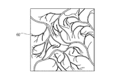
表示制御回路58は、CPU54の制御の下、新たにフレームメモリ56に記憶された2色の近景用特殊光画像データを読み出す。そして、図7に示すように、表示制御回路58は、各近景用特殊光画像データ基づき、近景用特殊光観察像60をモニタ14に表示させる。
The
近景観察時には、両狭帯域光用フィルタ41B,41Gの面積の比率を2:1にすることで、B出射時間とG出射時間との比率が2:1になる。このため、特殊光観察用回転フィルタ32が一回転する間の3フレーム分の撮像期間のうち、2フレーム分の撮像期間はB狭帯域光Bnの光電変換による信号電荷の蓄積等が行われる。その結果、近景用特殊光観察像60では、緑色狭帯域画像よりも青色狭帯域画像が強調されるので、表層血管とその周辺の生体組織とコントラストがより高くなり、表層血管をより強調して表示することができる。これにより、近景観察時には、早期癌などによる病変が現れやすい表層血管を集中的に観察することができる。
At the time of near-field observation, the ratio of the area of both the narrowband
図5に戻って、観察状態判定部57は、CPU54の制御の下、新たにフレームメモリ56に記憶された近景用特殊光画像データの輝度信号に基づき、撮影時の露光量を検出する。次いで、観察状態判定部57は、露光量の検出結果が一定値以上である場合には、近景観察状態にあると判定して、この判定結果をCPU54に送る。この判定結果を受けて、CPU54は近景観察モードを継続する。以下、観察状態判定部57の判定結果が遠景観察状態に変わるまで、近景用特殊光画像データの取得と、近景用特殊光観察像60の表示と、露光量の検出と、観察状態の判定とが繰り返し実行される。
Returning to FIG. 5, under the control of the
観察状態判定部57は、露光量の検出結果が一定値未満になった場合には、観察状態が遠景観察状態に切り替わったと判定し、この判定結果をCPU54へ送る。この判定結果を受けて、CPU54は特殊光観察モードを遠景観察モードに切り替える。
The observation
次いで、CPU54は、フィルタシフト機構33に対して遠景観察切替指令を発する。この指令を受けて、フィルタシフト機構33は、特殊光観察用回転フィルタ32を遠景観察挿入位置に移動させる。特殊光観察用回転フィルタ32の回転は継続しているので、第2B狭帯域光用フィルタ42Bと第2G狭帯域光用フィルタ42Gとが交互に繰り返し広帯域光BBの光路内に挿入される。これにより、患者の管内に、B狭帯域光Bn及びG狭帯域光Gnが交互に繰り返し照射される。
Next, the
近景観察モード時と同様に、患者の管内で反射/散乱した各色狭帯域光Bn,Gnが観察窓19などを通してCCD44に入射する。この際に、挿入フィルタ判別部54aは、各狭帯域光用フィルタ42B,42Gのいずれが広帯域光BBの光路内に挿入されているかを判別する。そして、この判別結果に基づき、CPU54は、撮像制御部46を制御してCCD44に対して駆動信号を送る。
As in the foreground viewing mode, the narrow-band lights Bn and Gn reflected / scattered in the patient's tube enter the
図6(C)に示すように、各狭帯域光用フィルタ42B,42Gの面積の比率は1:2であるので、CCD44は、特殊光観察用回転フィルタ32が1/3回転する間の1フレーム分の撮像期間に、B狭帯域光Bnを光電変換して青色狭帯域撮像信号をAFE45へ出力する。次いで、CCD44は、特殊光観察用回転フィルタ32がさらに2/3回転する間の2フレーム分の撮像期間に、G狭帯域光Gnを光電変換して緑色狭帯域撮像信号をAFE45へ出力する。これにより、AFE45から青色狭帯域撮像信号と緑色狭帯域撮像信号がDSP55に送られ、このDSP55にて2色の遠景用特殊光画像データが生成されてフレームメモリ56に記憶される。
As shown in FIG. 6C, the ratio of the area of each of the narrowband
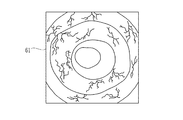
表示制御回路58は、CPU54の制御の下、新たにフレームメモリ56に記憶された2色の遠景用特殊光画像データを読み出す。そして、図8に示すように、表示制御回路58は、2色の遠景用特殊光画像データ基づき、遠景用特殊光観察像61をモニタ14に表示させる。
Under the control of the
遠景観察時には、各狭帯域光用フィルタ42B,42Gの面積の比率を1:2にすることで、B出射時間とG出射時間との比率が1:2になる。このため、特殊光観察用回転フィルタ32が一回転する間の3フレーム分の撮像期間のうち、2フレーム分の撮像期間はG狭帯域光Bnの光電変換による信号電荷の蓄積等が行われる。その結果、遠景用特殊光観察像61では、青色狭帯域画像よりも緑色狭帯域画像が強調される。
At the time of distant view observation, the ratio of the area of each of the narrowband
ここで、G狭帯域光GnはB狭帯域光Bnと比較して、ヘモグロビンの吸収係数や生体組織内での散乱係数が低いため、生体組織内をより深くかつより広く拡散していく。このため、緑色狭帯域画像が強調された遠景用特殊光観察像61では管内の粘膜等がより明るくなる。その結果、遠景観察では、表層血管及び中深層血管の位置関係を含む被観察部位の全体の状態が観察し易くなる。 Here, since the G narrowband light Gn has a lower hemoglobin absorption coefficient and a scattering coefficient in the living tissue than the B narrowband light Bn, it diffuses deeper and more widely in the living tissue. For this reason, in the distant special light observation image 61 in which the green narrow band image is emphasized, the mucous membrane in the tube becomes brighter. As a result, in the distant view observation, it becomes easy to observe the entire state of the site to be observed including the positional relationship between the surface blood vessels and the middle and deep blood vessels.
図5に戻って、観察状態判定部57は、近景観察モード時と同様にして撮影時の露光量を検出する。そして、観察状態判定部57は、露光量の検出結果が一定値未満である場合には、遠景観察状態が維持されていると判定する。この場合に、CPU54は遠景観察モードを継続する。以下、観察状態判定部57の判定結果が近景観察状態に変わるまで、遠景用特殊光画像データの取得と、遠景用特殊光観察像61の表示と、遠景用特殊光画像データに基づく露光量の検出と、観察状態の判定とが繰り返し実行される。
Returning to FIG. 5, the observation
逆に、観察状態判定部57の判定結果が近景観察状態に変わった場合には、CPU54は特殊光観察モードを近景観察モードに切り替える。これにより、再び近景用特殊光画像データの取得と、近景用特殊光観察像60の表示と、露光量の検出と、観察状態の判定とが繰り返し実行される。
Conversely, when the determination result of the observation
以下、特殊光観察が終了するまで、観察状態判定部57が近景観察状態と判定した場合には「B出射時間>G出射時間」となり青色狭帯域画像が強調された状態で特殊光観察が行われ、逆に遠景観察状態と判定した場合には「B出射時間<G出射時間」となり緑色狭帯域画像が強調された状態で特殊光観察が行われる。これにより、近景観察や遠景観察などの撮影条件に応じた良好な特殊光画像が得られる。
Hereinafter, when the observation
上記第1実施形態では、光源装置13内に通常観察用回転フィルタ31と特殊光観察用回転フィルタ32とを別個に設けているが、例えば、図9に示す統合回転フィルタ63のように、近景観察用フィルタエリア39及び遠景観察用フィルタエリア40の内側に、各色フィルタ37B,37G,37Rからなる通常観察用フィルタエリア64を設けてもよい。この場合に、フィルタシフト機構33は、通常観察モード時に通常観察用フィルタエリア64が広帯域光BBの光路内に挿入されるように、統合回転フィルタ63を移動させる。なお、これ以外の動作については第1実施形態と同じであるので説明は省略する。
In the first embodiment, the normal
[第2実施形態]
次に本発明の第2実施形態の内視鏡システムについて説明を行う。上記第1実施形態では、各狭帯域光用フィルタ41B,41Gの面積の比率や各狭帯域光用フィルタ42B,42Gの面積の比率を変えることにより、B出射時間とG出射時間との比率を変えている。これに対して、第2実施形態の内視鏡システムでは、特殊光観察用回転フィルタの回転を制御することで、B出射時間とG出射時間との比率を変える。
[Second Embodiment]
Next, an endoscope system according to a second embodiment of the present invention will be described. In the first embodiment, the ratio of the B emission time to the G emission time is changed by changing the area ratio of the narrowband
図10に示すように、第2実施形態の内視鏡システムは、第1実施形態とは異なる光源装置66及びプロセッサ装置67を備える点を除けば、基本的には第1実施形態と同じ構成であり、この第1実施形態と機能・構成上同一のものについては同一符号を付してその説明は省略する。
As shown in FIG. 10, the endoscope system according to the second embodiment is basically the same as the first embodiment except that the endoscope system includes a
光源装置66は、第1実施形態とは異なる特殊光観察用回転フィルタ69及びフィルタ回転機構70を備える点を除けば、第1実施形態の光源装置13と基本的に同じ構成であるため、この第1実施形態と同じ構成についてはここでは説明を省略する。
The
特殊光観察用回転フィルタ69は、広帯域光BBのうちB狭帯域光Bnを透過するB狭帯域光用フィルタ71Bと、広帯域光BBのうちG狭帯域光Gnを透過するG狭帯域光用フィルタ71Gとを備える半割りのフィルタである。これら両狭帯域光用フィルタ71B,71Gは、それぞれ第1実施形態の各狭帯域光フィルタと同じ光透過性を有するものが用いられる。
The special light
フィルタ回転機構70は、特殊光観察モード時に、各狭帯域光用フィルタ71B,71Gが交互にそれぞれ広帯域光BBの光路内に挿入された状態で一時停止するように、特殊光観察用回転フィルタ69を180°のピッチで間欠的に回転させる。B狭帯域光用フィルタ71Bを光路内で一時停止させる停止時間(以下、B停止時間という)と、G狭帯域光用フィルタ71Gを光路内で一時停止させる停止時間(以下、G停止時間という)とはそれぞれ近景観察モード及び遠景観察モード別に予め定められている。
The
具体的に近景観察モードでは、B停止時間とG停止時間との比率が、近景観察モードで予め定められたB出射時間とG出射時間との比率(B出射時間>G出射時間)に合わせて設定されている。また、遠景観察モードでは、B停止時間とG停止時間との比率が、遠景観察モードで予め定められたB出射時間とG出射時間との比率(B出射時間<G出射時間)に合わせて設定されている。 Specifically, in the foreground observation mode, the ratio between the B stop time and the G stop time is set in accordance with the ratio of the B exit time and the G exit time (B exit time> G exit time) set in advance in the near view observation mode. Is set. In the distant view observation mode, the ratio between the B stop time and the G stop time is set in accordance with the ratio of the B exit time and the G exit time (B exit time <G exit time) predetermined in the distant view observation mode. Has been.
なお、フィルタシフト機構33(図2参照)は、特殊光観察用回転フィルタ69を、広帯域光BBの光路内に挿入される挿入位置と、この光路内から退避した退避位置との間で移動させる。
The filter shift mechanism 33 (see FIG. 2) moves the special light
プロセッサ装置67は、CPU73と、データテーブル74が格納されたメモリ75とを備える点を除けば、第1実施形態のプロセッサ装置12と基本的に同じ構成である。また、CPU73についても、特殊光観察モード時にフィルタ回転制御部(光源制御手段)73aとして機能する点を除けば、第1実施形態のCPU54と基本的に同じである。
The
データテーブル74には、近景観察モード及び遠景観察モードのそれぞれにおけるB停止時間、G停止時間が設定されている。近景観察モードではB停止時間を「2T」、G停止時間を「T」に設定するともに、遠景観察モードではB停止時間を「T」、G停止時間を「2T」に設定している。ここで「T」は、特に限定はされないが、例えば通常観察モード時における各色フィルタ37B,37G,37Rの個々の光路挿入時間(すなわち、B光、G光、R光の個々の出射時間)である。
In the data table 74, the B stop time and the G stop time in each of the near view observation mode and the distant view observation mode are set. In the near view observation mode, the B stop time is set to “2T” and the G stop time is set to “T”. In the far view observation mode, the B stop time is set to “T” and the G stop time is set to “2T”. Here, “T” is not particularly limited, but for example, is an individual optical path insertion time of each of the
フィルタ回転制御部73aは、特殊光観察モード時に、観察状態判定部57の判定結果とメモリ75内のデータテーブル74とに基づき、フィルタ回転機構70を制御して特殊光観察用回転フィルタ69を間欠回転させる。
In the special light observation mode, the filter rotation control unit 73a controls the
次に、図11に示すフローチャートを用いて第2実施形態の内視鏡システムの作用、特に特殊光観察モード時における動作について詳しく説明する。なお、通常観察モード時における動作については上記第1実施形態と基本的に同じであるので、ここでは説明を省略する。 Next, the operation of the endoscope system according to the second embodiment, particularly the operation in the special light observation mode will be described in detail with reference to the flowchart shown in FIG. Since the operation in the normal observation mode is basically the same as that in the first embodiment, description thereof is omitted here.
CPU73は、観察モード切替スイッチ59が特殊光観察モード切り替えられたときに、フィルタシフト機構33に対して挿入切替指令を発する。この指令を受けてフィルタシフト機構33は、通常観察用回転フィルタ31を退避位置に移動させるとともに、特殊光観察用回転フィルタ69を挿入位置に移動させる。
The
初期状態では近景観察モードに設定されているので、フィルタ回転制御部73aは、メモリ75内のデータテーブル74を参照してB停止時間を「2T」、G停止時間を「T」にそれぞれ決定する。次いで、フィルタ回転制御部73aは、フィルタ回転機構70に対して回転指令を発する。
Since the foreground observation mode is set in the initial state, the filter rotation control unit 73a refers to the data table 74 in the
フィルタ回転機構70は、フィルタ回転制御部73aからの回転指令を受けて、広帯域光BBの光路内にB狭帯域光用フィルタ71Bが挿入された状態で「2T」時間だけ特殊光観察用回転フィルタ69を一時停止させる。次いで、特殊光観察用回転フィルタ69を180°回転させて、G狭帯域光用フィルタ71Gを広帯域光BBの光路内に挿入させた状態で、「T」時間だけ特殊光観察用回転フィルタ69を一時停止させる。そして、再び特殊光観察用回転フィルタ69を180°回転させる。
The
以下同様に、「2T」時間のB狭帯域光用フィルタ71Bの挿入・一時停止、及び「T」時間のG狭帯域光用フィルタ71Gの挿入・一時停止が交互に繰り返される。これにより、特殊光観察用回転フィルタ69からライトガイド43などを経て、患者の管内へB狭帯域光Bn及びG狭帯域光Gnが交互に繰り返し出射される。そして、この管内で反射/散乱したB狭帯域光Bn及びG狭帯域光Gnが、集光レンズ51などを通してCCD44に入射する。
Similarly, the insertion / pause of the B narrowband
この際に、挿入フィルタ判別部54aは、フィルタ回転機構70の動作を監視するなどして、各狭帯域光用フィルタ71B,71Gのいずれが広帯域光BBの光路上に挿入されているかを判別する。そして、この判別結果に基づき、CPU73は、撮像制御部46を制御してCCD44に対して駆動信号を送る。
At this time, the insertion filter discriminating unit 54a discriminates which of the narrowband
図12(A)に示すように、時間「T」は通常観察用回転フィルタ31が1/3回転する間の1フレーム分の撮像期間に等しいので、CCD44は、2フレーム分の撮像期間となる「2T」のB停止時間に、B狭帯域光Bnを光電変換して青色狭帯域撮像信号をAFE45へ出力する。次いで、CCD44は、1フレーム分の撮像期間となる次の「1T」のG停止時間に、G光を光電変換して緑色狭帯域撮像信号をAFE45へ出力する。これにより、第1実施形態と同様に、近景用特殊光画像データの生成と、近景用特殊光観察像60の表示とが実行される。
As shown in FIG. 12A, since the time “T” is equal to the imaging period for one frame while the normal
このように、近景観察時にはB停止時間とG停止時間との比率を2:1にすることにより、B出射時間とG出射時間との比率を2:1にすることができる。これにより、近景観察時に表層血管をより強調可能という、第1実施形態との同様の効果が得られる。 Thus, the ratio of the B emission time to the G emission time can be set to 2: 1 by setting the ratio of the B stop time and the G stop time to 2: 1 during close-up viewing. Thereby, the same effect as 1st Embodiment that the superficial blood vessel can be emphasized more at the time of near view observation is acquired.
以下、第1実施形態と同様に、観察状態判定部57の判定結果が遠景観察状態に変わるまで、近景用特殊光画像データの取得と、近景用特殊光観察像60の表示と、露光量の検出と、観察状態の判定とが繰り返し実行される。そして、観察状態判定部57の判定結果が遠景観察状態に変わった場合には、CPU73は特殊光観察モードを遠景観察モードに切り替える。
Hereinafter, as in the first embodiment, until the determination result of the observation
遠景観察モードに切り替わると、フィルタ回転制御部73aは、データテーブル74を参照してB停止時間を「T」、G停止時間を「2T」にそれぞれ決定した後、フィルタ回転機構70に対して回転指令を発する。これにより、「T」時間のB狭帯域光用フィルタ71Bの挿入・一時停止、及び「2T」時間のG狭帯域光用フィルタ71Gの挿入・一時停止が交互に繰り返し実行される。こうして、各狭帯域光Bn,Gnが患者の管内に交互に繰り返し照射される。
When switched to the distant view observation mode, the filter rotation control unit 73a refers to the data table 74 and determines the B stop time as “T” and the G stop time as “2T”, and then rotates the
患者の管内で反射/散乱した各狭帯域光Bn,Gnは、観察窓19などを通して順次にCCD44に入射する。そして、CPU73は、挿入フィルタ判別部54aの判別結果に基づき、撮像制御部46を制御してCCD44に対して駆動信号を送る。
The narrow-band lights Bn and Gn reflected / scattered in the patient's tube enter the
図12(B)に示すように、CCD44は、1フレーム分の撮像期間となる「T」のB停止時間に、B狭帯域光Bnを光電変換して青色狭帯域撮像信号をAFE45へ出力する。次いで、CCD44は、2フレーム分の撮像期間となる次の「2T」のG停止時間に、G光を光電変換して緑色画像信号をAFE45へ出力する。これにより、第1実施形態と同様に、遠景用特殊光画像データの生成と、遠景用特殊光観察像61の表示とが実行される。
As shown in FIG. 12B, the
このように、遠景観察時にはB停止時間とG停止時間との比率を1:2にすることにより、B出射時間とG出射時間との比率を1:2にすることができる。これにより、管内の粘膜等がより明るくなって被観察部位の全体の状態が観察し易くなるという、第1実施形態との同様の効果が得られる。そして、観察状態判定部57の判定結果が遠景観察状態に変わるまで、遠景用特殊光画像データの取得と、遠景用特殊光観察像61の表示と、遠景用特殊光画像データに基づく露光量の検出と、観察状態の判定とが繰り返し実行される。なお、観察状態判定部57が近景検察状態であると判定した場合には、CPU73は特殊光観察モードを近景観察モードに切り替える。
As described above, the ratio of the B emission time to the G emission time can be set to 1: 2 by setting the ratio of the B stop time and the G stop time to 1: 2 at the time of distant view observation. Thereby, the same effect as 1st Embodiment that the mucous membrane etc. in a pipe | tube becomes brighter and it becomes easy to observe the whole state of a to-be-observed site | part is acquired. Then, until the determination result of the observation
以下、特殊光観察が終了するまで、第1実施形態と同様に近景観察モード下では「B出射時間>G出射時間」となる状態で特殊光観察が行われ、逆に遠景観察モード下では「B出射時間<G出射時間」となる状態で特殊光観察が行われる。その結果、第1実施形態と同様に、近景観察や遠景観察などの撮影条件に応じた良好な特殊光画像が得られる。 Thereafter, until the special light observation is completed, the special light observation is performed in the state where “B emission time> G emission time” in the near view observation mode as in the first embodiment, and conversely, in the far view observation mode, “ Special light observation is performed in a state where B emission time <G emission time ”. As a result, similar to the first embodiment, a good special light image can be obtained in accordance with shooting conditions such as foreground observation and distant view observation.
上記第2実施形態では、特殊光観察用回転フィルタ69が通常観察用回転フィルタ31と別体に設けられているが、例えば、図13に示す統合回転フィルタ78のように、各狭帯域光用フィルタ71B,71Gの内側に、各色フィルタ37B,37G,37Rからなる通常観察用フィルタエリア79を設けてもよい。この統合回転フィルタ78では、通常観察モード時に通常観察用フィルタエリア79が広帯域光BBの光路内に挿入され、特殊光観察モード時に各狭帯域光用フィルタ71B,71Gが光路内に挿入される。
In the second embodiment, the special light
上記第2実施形態では、特殊光観察用回転フィルタ69を間欠回転させているが、特殊光観察用回転フィルタ69の回転を一時停止させる必要はない。例えば、B狭帯域光用フィルタ71Bが広帯域光BBの光路内に挿入される挿入時間と、G狭帯域光用フィルタ71Gを光路内に挿入される挿入時間とが、各観察モードごとに定められたB出射時間、G出射時間にそれぞれ等しくなるように、特殊光観察用回転フィルタ69の回転速度を制御してもよい。
In the second embodiment, the special light
上記第1実施形態では、B出射時間<G出射時間となるように、遠景観察用フィルタエリア40の各狭帯域光用フィルタ42B,42Gの面積を設定しているが、例えば、図14に示す特殊光観察用回転フィルタ81の遠景観察用フィルタエリア82のように、B出射時間=G出射時間となるように各狭帯域光用フィルタ83B,83Gの面積を設定してもよい。この場合には、遠景観察時において表層血管と中深層血管とを共に強調表示した観察像が得られため、表層血管及び中深層血管の位置関係がより把握し易くなる。なお、第2実施形態で同様のことを行う場合には、B停止時間=G停止時間となるように特殊光観察用回転フィルタ69の回転を制御すればよい。
In the first embodiment, the areas of the narrowband
上記各実施形態では、特殊光観察モード時にG狭帯域光とB狭帯域光とを光源装置13から出射させているが、照明光として用いる狭帯域光の波長帯域は特に限定されず、例えば赤色狭帯域光を含む各色狭帯域光を光源装置13から出射させてもよい。
In each of the above embodiments, the G narrowband light and the B narrowband light are emitted from the
上記各実施形態では、プロセッサ装置12,67のCPUにより光源装置13,66の各部を制御しているが、これら各部を制御するCPU等の制御部を光源装置13,66に設けてもよい。
In the above embodiments, the CPUs of the
上記実施形態では、光源装置13から電子内視鏡11へ広帯域光や狭帯域光を出射しているが、これら広帯域光や狭帯域光の光源を挿入部先端部16a内に設けてもよい。
In the above embodiment, broadband light and narrow band light are emitted from the
上記各実施形態では、撮影条件として近景観察及び遠景観察を例に挙げて説明しているが、撮影条件が例えば被観察部位の反射率の高/低などであってもよい。具体的にこの場合には、観察画像を解析するなどの方法で被観察部位の反射率を求めて、被観察部位の反射率が高いときはB出射時間>G出射時間となり、被観察部位の反射率が低いときはB出射時間<G出射時間となるように出射時間の切替制御を行う。 In each of the above-described embodiments, foreground observation and distant view observation are described as examples of imaging conditions. However, the imaging conditions may be, for example, high / low reflectance of the site to be observed. Specifically, in this case, the reflectance of the observation site is obtained by a method such as analyzing the observation image. When the reflectance of the observation site is high, B emission time> G emission time, and When the reflectance is low, emission time switching control is performed so that B emission time <G emission time.
上記各実施形態では、B出射時間とG出射時間との比率が2:1になるように各フィルタの面積の比率や、B,G停止時間の比率を設定しているが、この比率は適宜変更してよい。 In each of the above embodiments, the ratio of the area of each filter and the ratio of the B and G stop times are set so that the ratio of the B emission time to the G emission time is 2: 1. You may change it.
上記実施形態では、2種類の特定の波長の光を利用して表層血管や中深層血管の特殊光観察を行う内視鏡システムについて例に挙げて説明を行ったが、2種類の特定の波長の光を利用して行う蛍光観察(Auto Fluorescence Imaging)、赤外光観察(Infra Red Imaging)、光線力学的診断(Photodynamic diagnosis)などの各種観察、診断に用いられる内視鏡システムに本発明を適用することができる。 In the above-described embodiment, the endoscope system that performs the special light observation of the surface blood vessel and the middle-deep blood vessel using light of two types of specific wavelengths has been described as an example, but the two types of specific wavelengths are described. The present invention is applied to an endoscope system used for various observations and diagnoses such as fluorescence observation (Auto Fluorescence Imaging), infrared light observation (Infra Red Imaging), and photodynamic diagnosis (Photodynamic diagnosis). Can be applied.
10 内視鏡システム
11 電子内視鏡
12,67 プロセッサ装置
13,68 光源装置
32,69 特殊光観察用回転フィルタ
33 フィルタシフト機構
34,70 フィルタ回転機構
39 近景観察用フィルタエリア
40 遠景観察用フィルタエリア
41B,41G 第1青色狭帯域光用フィルタ、第1緑色狭帯域光用フィルタ
42B,42G 第2青色狭帯域光用フィルタ、第2緑色狭帯域光用フィルタ
54,73 CPU
71B,71G 青色狭帯域光用フィルタ、緑色狭帯域光用フィルタ
73a フィルタ回転制御部
74 データテーブル
DESCRIPTION OF
71B, 71G Blue narrowband light filter, green narrowband light filter 73a Filter
Claims (10)
前記第1〜第2の狭帯域光がそれぞれ照射された被観察部位を撮像して前記被観察部位の観察像を得る撮像手段と、
前記狭帯域光源から出射される前記第1狭帯域光の第1出射時間と前記第2狭帯域光の第2出射時間とを制御する光源制御手段と、
を備えることを特徴とする内視鏡システム。 A narrow-band light source that repeatedly emits first and second narrow-band lights having different wavelength bands used for special light observation in a predetermined order;
Imaging means for obtaining an observation image of the observed site by imaging the observed site irradiated with each of the first to second narrowband lights;
Light source control means for controlling a first emission time of the first narrowband light emitted from the narrowband light source and a second emission time of the second narrowband light;
An endoscope system comprising:
前記光源制御手段は、前記撮影条件検出手段が検出した前記撮影条件に応じて前記第1〜第2出射時間をそれぞれ変えることを特徴とする請求項1記載の内視鏡システム。 Based on the observation image obtained by the imaging means, provided with imaging condition detection means for detecting a predetermined imaging condition at the time of acquisition,
The endoscope system according to claim 1, wherein the light source control unit changes the first and second emission times according to the imaging condition detected by the imaging condition detection unit.
前記撮影条件検出手段は、前記撮影条件として、内視鏡の先端部と前記被観察部位との距離が近い状態にある近景観察状態または前記距離が遠い状態にある遠景観察状態にあるか否かを検出し、
前記光源制御手段は、前記撮影条件検出手段が前記近景観察状態を検出した場合には前記第1出射時間が前記第2出射時間よりも長くなり、前記遠景観察状態を検出した場合には前記第2出射時間が前記第1出射時間よりも長くなるように、前記狭帯域光源を制御することを特徴とする請求項2記載の内視鏡システム。 The second narrowband light has a wavelength band longer than the wavelength band of the first narrowband light,
Whether the imaging condition detection means is in a near-field observation state where the distance between the distal end portion of the endoscope and the site to be observed is close or a distant view observation state where the distance is far as the imaging condition Detect
The light source control means is configured such that the first emission time is longer than the second emission time when the photographing condition detection means detects the near view observation state, and the first light emission control time when the distant view observation state is detected. The endoscope system according to claim 2, wherein the narrow-band light source is controlled so that two emission times are longer than the first emission time.
白色の広帯域光を出射する広帯域光源と、
前記広帯域光のうち前記第1狭帯域光を透過させる第1フィルタ、及び前記広帯域光のうち前記第2狭帯域光を透過させる第2フィルタを有する略環状のフィルタエリアが、回転軸を中心として前記撮影条件ごとに同心円状に設けられてなる回転フィルタと、
前記回転フィルタをその半径方向に移動させて、個々の前記フィルタエリアのいずれかを選択的に前記広帯域光の光路に挿入させるフィルタエリア挿入手段と、
前記回転軸を中心に前記回転フィルタを回転させるフィルタ回転手段とを備えており、
前記回転フィルタは、個々の前記フィルタエリアにおける前記第1〜第2フィルタの面積の比率が、前記撮影条件ごとに予め定められた前記第1〜第2出射時間の比率に合わせて設定されていることを特徴とする請求項2または3記載の内視鏡システム。 The narrow-band light source is
A broadband light source that emits white broadband light;
A substantially annular filter area having a first filter that transmits the first narrowband light of the broadband light and a second filter that transmits the second narrowband light of the broadband light, with a rotation axis as a center. A rotation filter provided concentrically for each imaging condition;
A filter area inserting means for moving the rotary filter in a radial direction thereof and selectively inserting one of the individual filter areas into the optical path of the broadband light;
Filter rotating means for rotating the rotary filter around the rotation axis,
In the rotary filter, the ratio of the areas of the first and second filters in each filter area is set in accordance with the ratio of the first and second emission times determined in advance for each imaging condition. The endoscope system according to claim 2 or 3, characterized by the above.
白色の広帯域光を出射する広帯域光源と、
前記広帯域光の光路に配置され、前記広帯域光のうち前記第1狭帯域光を透過させる第1フィルタ、及び前記広帯域光のうち前記第2狭帯域光を透過させる第2フィルタを有する回転フィルタと、
前記回転フィルタを回転させて、前記第1フィルタ及び前記第2フィルタを交互に前記光路に挿入させるフィルタ回転手段とを備えており、
前記光源制御手段は、前記第1〜第2フィルタがそれぞれ前記光路に挿入される挿入時間が、前記第1〜第2出射時間の設定値にそれぞれ等しくなるように前記フィルタ回転手段を制御することを特徴とする請求項7記載の内視鏡システム。 The narrow-band light source is
A broadband light source that emits white broadband light;
A rotary filter disposed in the optical path of the broadband light and having a first filter that transmits the first narrowband light of the broadband light, and a second filter that transmits the second narrowband light of the broadband light; ,
Filter rotation means for rotating the rotary filter and alternately inserting the first filter and the second filter into the optical path;
The light source control means controls the filter rotation means so that the insertion time for inserting the first and second filters into the optical path is equal to the set value of the first and second emission times, respectively. The endoscope system according to claim 7.
前記第1〜第2フィルタがそれぞれ前記光路内で一時停止する時間が、前記第1〜第2出射時間の設定値にそれぞれ等しくなることを特徴とする請求項8記載の内視鏡システム。 The filter rotating means intermittently rotates the rotary filter such that the first filter and the second filter are temporarily stopped in a state where each of the first filter and the second filter is inserted in the optical path of the broadband light.
9. The endoscope system according to claim 8, wherein a time during which each of the first and second filters is temporarily stopped in the optical path is equal to a set value of the first and second emission times. 10.
Priority Applications (2)
| Application Number | Priority Date | Filing Date | Title |
|---|---|---|---|
| JP2010277952A JP5371941B2 (en) | 2010-12-14 | 2010-12-14 | Endoscope system |
| CN201110381954.8A CN102551645B (en) | 2010-12-14 | 2011-11-25 | Endoscopic system |
Applications Claiming Priority (1)
| Application Number | Priority Date | Filing Date | Title |
|---|---|---|---|
| JP2010277952A JP5371941B2 (en) | 2010-12-14 | 2010-12-14 | Endoscope system |
Publications (2)
| Publication Number | Publication Date |
|---|---|
| JP2012125331A true JP2012125331A (en) | 2012-07-05 |
| JP5371941B2 JP5371941B2 (en) | 2013-12-18 |
Family
ID=46399243
Family Applications (1)
| Application Number | Title | Priority Date | Filing Date |
|---|---|---|---|
| JP2010277952A Active JP5371941B2 (en) | 2010-12-14 | 2010-12-14 | Endoscope system |
Country Status (2)
| Country | Link |
|---|---|
| JP (1) | JP5371941B2 (en) |
| CN (1) | CN102551645B (en) |
Cited By (2)
| Publication number | Priority date | Publication date | Assignee | Title |
|---|---|---|---|---|
| WO2016056332A1 (en) * | 2014-10-06 | 2016-04-14 | オリンパス株式会社 | Image acquisition system |
| JP2016152873A (en) * | 2015-02-20 | 2016-08-25 | Hoya株式会社 | Light source apparatus |
Citations (4)
| Publication number | Priority date | Publication date | Assignee | Title |
|---|---|---|---|---|
| JPH07240931A (en) * | 1993-12-22 | 1995-09-12 | Eastman Kodak Co | Color sequential electronic camera |
| JP2000262459A (en) * | 1999-03-18 | 2000-09-26 | Olympus Optical Co Ltd | Endoscope device |
| JP2005013279A (en) * | 2003-06-23 | 2005-01-20 | Olympus Corp | Endoscope apparatus |
| JP2010136748A (en) * | 2008-12-09 | 2010-06-24 | Fujifilm Corp | Endoscope apparatus and control method thereof |
Family Cites Families (5)
| Publication number | Priority date | Publication date | Assignee | Title |
|---|---|---|---|---|
| EP2319390B1 (en) * | 2000-07-21 | 2016-04-20 | Olympus Corporation | Endoscope apparatus |
| JP2005006856A (en) * | 2003-06-18 | 2005-01-13 | Olympus Corp | Endoscope apparatus |
| WO2006132191A1 (en) * | 2005-06-08 | 2006-12-14 | Olympus Medical Systems Corp. | Endoscope and image processing device |
| JP5191090B2 (en) * | 2005-07-15 | 2013-04-24 | オリンパスメディカルシステムズ株式会社 | Endoscope device |
| EP2179687B1 (en) * | 2008-10-22 | 2012-12-26 | FUJIFILM Corporation | Endoscope apparatus and control method therefor |
-
2010
- 2010-12-14 JP JP2010277952A patent/JP5371941B2/en active Active
-
2011
- 2011-11-25 CN CN201110381954.8A patent/CN102551645B/en active Active
Patent Citations (4)
| Publication number | Priority date | Publication date | Assignee | Title |
|---|---|---|---|---|
| JPH07240931A (en) * | 1993-12-22 | 1995-09-12 | Eastman Kodak Co | Color sequential electronic camera |
| JP2000262459A (en) * | 1999-03-18 | 2000-09-26 | Olympus Optical Co Ltd | Endoscope device |
| JP2005013279A (en) * | 2003-06-23 | 2005-01-20 | Olympus Corp | Endoscope apparatus |
| JP2010136748A (en) * | 2008-12-09 | 2010-06-24 | Fujifilm Corp | Endoscope apparatus and control method thereof |
Cited By (3)
| Publication number | Priority date | Publication date | Assignee | Title |
|---|---|---|---|---|
| WO2016056332A1 (en) * | 2014-10-06 | 2016-04-14 | オリンパス株式会社 | Image acquisition system |
| US10191271B2 (en) | 2014-10-06 | 2019-01-29 | Olympus Corporation | Image pickup system |
| JP2016152873A (en) * | 2015-02-20 | 2016-08-25 | Hoya株式会社 | Light source apparatus |
Also Published As
| Publication number | Publication date |
|---|---|
| CN102551645B (en) | 2015-09-16 |
| CN102551645A (en) | 2012-07-11 |
| JP5371941B2 (en) | 2013-12-18 |
Similar Documents
| Publication | Publication Date | Title |
|---|---|---|
| JP5303012B2 (en) | Endoscope system, processor device for endoscope system, and method for operating endoscope system | |
| JP5419931B2 (en) | Endoscope system, light source device, and operation method of endoscope system | |
| JP5631764B2 (en) | Endoscope system and operating method thereof | |
| JP5623469B2 (en) | ENDOSCOPE SYSTEM, ENDOSCOPE SYSTEM PROCESSOR DEVICE, AND ENDOSCOPE CONTROL PROGRAM | |
| JP5306447B2 (en) | Transmittance adjusting device, observation device, and observation system | |
| WO2013005533A1 (en) | Endoscope system, endoscope system processor and image display method | |
| JP5331860B2 (en) | Endoscope system and light source device | |
| JP5568489B2 (en) | Endoscope system and light source control method thereof | |
| WO2007116663A1 (en) | Endoscope device | |
| JP5623470B2 (en) | ENDOSCOPE SYSTEM, ENDOSCOPE SYSTEM PROCESSOR DEVICE, AND ENDOSCOPE CONTROL PROGRAM | |
| JP5148054B2 (en) | Imaging system | |
| US9596982B2 (en) | Endoscope system and composite image generation method | |
| JP5467971B2 (en) | Electronic endoscope system, processor device for electronic endoscope system, and method for operating electronic endoscope system | |
| JP5579672B2 (en) | Endoscope system and light source device | |
| US9788709B2 (en) | Endoscope system and image generation method to generate images associated with irregularities of a subject | |
| JP2013013559A (en) | Electronic endoscope system, light source device and method for controlling electronic endoscope system | |
| JP5271364B2 (en) | Endoscope system | |
| JP5877614B2 (en) | Endoscope system and method for operating endoscope system | |
| JP6017670B2 (en) | Endoscope system, operation method thereof, and processor device | |
| JP5509233B2 (en) | Electronic endoscope apparatus and method for operating the same | |
| JP5467970B2 (en) | Electronic endoscope system | |
| JP5371941B2 (en) | Endoscope system | |
| JP5518686B2 (en) | Endoscope system | |
| JP5208223B2 (en) | Endoscope system | |
| JP2015231467A (en) | Light source device for endoscope and endoscope system |
Legal Events
| Date | Code | Title | Description |
|---|---|---|---|
| A621 | Written request for application examination |
Free format text: JAPANESE INTERMEDIATE CODE: A621 Effective date: 20120605 |
|
| A131 | Notification of reasons for refusal |
Free format text: JAPANESE INTERMEDIATE CODE: A131 Effective date: 20130612 |
|
| A521 | Request for written amendment filed |
Free format text: JAPANESE INTERMEDIATE CODE: A523 Effective date: 20130730 |
|
| TRDD | Decision of grant or rejection written | ||
| A01 | Written decision to grant a patent or to grant a registration (utility model) |
Free format text: JAPANESE INTERMEDIATE CODE: A01 Effective date: 20130821 |
|
| A61 | First payment of annual fees (during grant procedure) |
Free format text: JAPANESE INTERMEDIATE CODE: A61 Effective date: 20130917 |
|
| R150 | Certificate of patent or registration of utility model |
Ref document number: 5371941 Country of ref document: JP Free format text: JAPANESE INTERMEDIATE CODE: R150 Free format text: JAPANESE INTERMEDIATE CODE: R150 |
|
| R250 | Receipt of annual fees |
Free format text: JAPANESE INTERMEDIATE CODE: R250 |
|
| R250 | Receipt of annual fees |
Free format text: JAPANESE INTERMEDIATE CODE: R250 |
|
| R250 | Receipt of annual fees |
Free format text: JAPANESE INTERMEDIATE CODE: R250 |
|
| R250 | Receipt of annual fees |
Free format text: JAPANESE INTERMEDIATE CODE: R250 |
|
| R250 | Receipt of annual fees |
Free format text: JAPANESE INTERMEDIATE CODE: R250 |
|
| R250 | Receipt of annual fees |
Free format text: JAPANESE INTERMEDIATE CODE: R250 |
|
| R250 | Receipt of annual fees |
Free format text: JAPANESE INTERMEDIATE CODE: R250 |
|
| R250 | Receipt of annual fees |
Free format text: JAPANESE INTERMEDIATE CODE: R250 |