JP2012125145A - Magnetic actuator, and micromirror and mirror system using the same - Google Patents
Magnetic actuator, and micromirror and mirror system using the same Download PDFInfo
- Publication number
- JP2012125145A JP2012125145A JP2011269187A JP2011269187A JP2012125145A JP 2012125145 A JP2012125145 A JP 2012125145A JP 2011269187 A JP2011269187 A JP 2011269187A JP 2011269187 A JP2011269187 A JP 2011269187A JP 2012125145 A JP2012125145 A JP 2012125145A
- Authority
- JP
- Japan
- Prior art keywords
- plate
- magnet
- magnetic
- mirror
- magnet yoke
- Prior art date
- Legal status (The legal status is an assumption and is not a legal conclusion. Google has not performed a legal analysis and makes no representation as to the accuracy of the status listed.)
- Granted
Links
- 239000004020 conductor Substances 0.000 claims abstract description 38
- 230000004907 flux Effects 0.000 claims abstract description 35
- 230000005415 magnetization Effects 0.000 claims abstract description 12
- 239000000463 material Substances 0.000 claims description 9
- 239000000725 suspension Substances 0.000 claims description 5
- WYTGDNHDOZPMIW-RCBQFDQVSA-N alstonine Natural products C1=CC2=C3C=CC=CC3=NC2=C2N1C[C@H]1[C@H](C)OC=C(C(=O)OC)[C@H]1C2 WYTGDNHDOZPMIW-RCBQFDQVSA-N 0.000 claims description 2
- 238000005452 bending Methods 0.000 claims description 2
- 230000000750 progressive effect Effects 0.000 claims description 2
- 125000006850 spacer group Chemical group 0.000 claims description 2
- 230000001678 irradiating effect Effects 0.000 claims 1
- 238000004519 manufacturing process Methods 0.000 description 6
- 238000009434 installation Methods 0.000 description 4
- 230000008901 benefit Effects 0.000 description 3
- 230000007423 decrease Effects 0.000 description 3
- 241001295925 Gegenes Species 0.000 description 2
- XEEYBQQBJWHFJM-UHFFFAOYSA-N Iron Chemical compound [Fe] XEEYBQQBJWHFJM-UHFFFAOYSA-N 0.000 description 2
- 239000010949 copper Substances 0.000 description 2
- 238000005260 corrosion Methods 0.000 description 2
- 230000007797 corrosion Effects 0.000 description 2
- 239000000696 magnetic material Substances 0.000 description 2
- 238000000034 method Methods 0.000 description 2
- 230000003287 optical effect Effects 0.000 description 2
- 229910052710 silicon Inorganic materials 0.000 description 2
- 239000010703 silicon Substances 0.000 description 2
- RYGMFSIKBFXOCR-UHFFFAOYSA-N Copper Chemical compound [Cu] RYGMFSIKBFXOCR-UHFFFAOYSA-N 0.000 description 1
- 230000008859 change Effects 0.000 description 1
- 239000002131 composite material Substances 0.000 description 1
- 229910052802 copper Inorganic materials 0.000 description 1
- 230000001419 dependent effect Effects 0.000 description 1
- 230000000694 effects Effects 0.000 description 1
- 230000005284 excitation Effects 0.000 description 1
- 238000003384 imaging method Methods 0.000 description 1
- 229910052742 iron Inorganic materials 0.000 description 1
- 238000004806 packaging method and process Methods 0.000 description 1
- 230000008569 process Effects 0.000 description 1
- 230000005855 radiation Effects 0.000 description 1
- 230000009467 reduction Effects 0.000 description 1
- 239000004065 semiconductor Substances 0.000 description 1
Images


Classifications
-
- G—PHYSICS
- G02—OPTICS
- G02B—OPTICAL ELEMENTS, SYSTEMS OR APPARATUS
- G02B26/00—Optical devices or arrangements for the control of light using movable or deformable optical elements
- G02B26/08—Optical devices or arrangements for the control of light using movable or deformable optical elements for controlling the direction of light
- G02B26/0816—Optical devices or arrangements for the control of light using movable or deformable optical elements for controlling the direction of light by means of one or more reflecting elements
- G02B26/0833—Optical devices or arrangements for the control of light using movable or deformable optical elements for controlling the direction of light by means of one or more reflecting elements the reflecting element being a micromechanical device, e.g. a MEMS mirror, DMD
- G02B26/085—Optical devices or arrangements for the control of light using movable or deformable optical elements for controlling the direction of light by means of one or more reflecting elements the reflecting element being a micromechanical device, e.g. a MEMS mirror, DMD the reflecting means being moved or deformed by electromagnetic means
-
- H—ELECTRICITY
- H02—GENERATION; CONVERSION OR DISTRIBUTION OF ELECTRIC POWER
- H02K—DYNAMO-ELECTRIC MACHINES
- H02K33/00—Motors with reciprocating, oscillating or vibrating magnet, armature or coil system
- H02K33/18—Motors with reciprocating, oscillating or vibrating magnet, armature or coil system with coil systems moving upon intermittent or reversed energisation thereof by interaction with a fixed field system, e.g. permanent magnets
-
- H—ELECTRICITY
- H02—GENERATION; CONVERSION OR DISTRIBUTION OF ELECTRIC POWER
- H02K—DYNAMO-ELECTRIC MACHINES
- H02K41/00—Propulsion systems in which a rigid body is moved along a path due to dynamo-electric interaction between the body and a magnetic field travelling along the path
- H02K41/02—Linear motors; Sectional motors
- H02K41/035—DC motors; Unipolar motors
- H02K41/0352—Unipolar motors
- H02K41/0354—Lorentz force motors, e.g. voice coil motors
-
- G—PHYSICS
- G02—OPTICS
- G02B—OPTICAL ELEMENTS, SYSTEMS OR APPARATUS
- G02B26/00—Optical devices or arrangements for the control of light using movable or deformable optical elements
- G02B26/08—Optical devices or arrangements for the control of light using movable or deformable optical elements for controlling the direction of light
- G02B26/10—Scanning systems
- G02B26/105—Scanning systems with one or more pivoting mirrors or galvano-mirrors
Abstract
Description
本発明は少なくとも1つの回転軸回りに回転可能に支承されたプレートを備えた磁気アクチュエータに関する。 The present invention relates to a magnetic actuator including a plate that is rotatably supported around at least one rotation axis.
マイクロミラーを磁気的に駆動するための方法は様々に存在する。静電駆動に対する磁気駆動の基本的な利点は、磁気ローレンツ力によって技術的に達成可能なトルクが静電気力によって実現可能なトルクよりも大きいことにある。 There are various methods for magnetically driving the micromirror. The basic advantage of magnetic drive over electrostatic drive is that the torque technically achievable with magnetic Lorentz force is greater than the torque achievable with electrostatic force.
特許文献1では、内側と外側の2つの回転軸回りに回転可能に支承されたジンバルミラーが提案されている。回転軸は互いに対して垂直である。2つのジンバル振動体上に内側軸と外側軸のためのそれぞれ1つのコイルが配置されている。磁場はチップ全体にわたってほぼ均一であり、2つの回転軸に対してそれぞれ45°の角度を有している。磁場を発生させるために、2つの装置が提案されている。第1の実施形態では、マイクロミラーが2つの硬磁石(永久磁石)の間に45°の角度で配置される。第2の実施形態では、逆の極性を有する4つの磁石が使用される。各軸が利用できる有効磁場は45°の角度によって係数V2の分だけ弱い。磁場発生のこの2つの実施形態は非常に嵩ばった構造を含意する。
特許文献2でも同様に、2つの軸回りに回転可能に支承されたジンバルミラーが提案されている。しかし、この装置では、2つの軸回りの駆動のために1つのコイルしか設けられていない。このコイルには、低周波の準静的信号も高周波の共振信号も供給される。共振信号はいわゆる「ロッキングモード」を介して内側軸の回転を励起する。
Similarly,
異なる極性の永久磁石と45°方向に磁場を発生させる磁束ガイド層の比較的複雑な構造は特許文献3に開示されている。各軸に対して垂直な有効磁場は同様に係数V2の分だけ弱い。
A relatively complicated structure of a magnetic flux guide layer that generates a permanent magnet of different polarity and a magnetic field in a 45 ° direction is disclosed in
特許文献4と特許文献5では、準静的な軸に対して垂直な磁場成分ないしモーメントを発生させるための装置が提案されている。それゆえ、これらの装置では、高周波交番磁場を印加すると、準静的な軸に対して垂直な軸4b回りの共振運動が誘発される。
In
ローレンツ力によって駆動されるマイクロミラーのこれら実施形態では、チップ表面の平面内を走る一方向磁場が実現される。優先方向からのずれは不完全な実現を意味する。技術的努力はこのような不完全な実施形態を最小限にすることに集中している。できるだけ高い一方向性を有する高い磁場を達成するために、使用される磁石・磁束ガイド構造は比較的嵩ばる。 In these embodiments of micromirrors driven by Lorentz forces, a unidirectional magnetic field running in the plane of the chip surface is realized. Deviation from the preferred direction means incomplete realization. Technical efforts are focused on minimizing such incomplete embodiments. In order to achieve a high magnetic field with as high a directionality as possible, the magnet / flux guide structures used are relatively bulky.
非特許文献1では、二軸マイクロスキャナを実現するための放射対称な磁場が提案されている。この放射対称磁場は、チップ平面に対して垂直な磁化方向を有する磁石によって実現される。それゆえ構造は比較的単純である。これは製造コストの点で有利である。磁力線の噴水状の流れはチップ平面内を走る放射状成分を含んでいる。技術的に有効なのはこれらの成分だけであり、他の成分は一部は有効でなく、一部はそれどころか不所望な横力をもたらす。非特許文献1に示されている有効な磁場強度は0.1Tである。
Non-Patent
非特許文献2では、2つの磁石の配置によって磁場を高めている。チップ表面に対して垂直な磁化方向を有する真ん中の円筒状磁石が逆極性のリング状磁石によって包囲されている。2つの磁石は円盤状の鉄板に固定されており、これによって磁束の一部が帰還される。この構成により、有効な磁場は0.5Tまで高められた。ただし、この構造は一方向磁場に基づいて動作するスキャナと同様にコスト高である。
In
マイクロミラーの製造価格を求める際にはパッケージングも考慮しなければならない。組立の最中に磁石を取り付けるのは非常にコスト集約的であると評価される。とりわけ、異なる極性の複数の磁石の取付けは、斥力のせいで取付けの際にさらに高いコストをもたらす。 Packaging must also be considered when determining the manufacturing price of micromirrors. Installing the magnet during assembly is evaluated as very cost intensive. In particular, the installation of a plurality of magnets of different polarities results in higher costs during installation due to repulsion.
例えばマグネットヨークの場合のように、1つの磁化方向を有する硬磁石を使用すれば、取付け後に磁化を行うことができ、これによってコストが大幅に削減される。 For example, if a hard magnet having one magnetization direction is used, as in the case of a magnet yoke, magnetization can be performed after attachment, thereby greatly reducing costs.
本発明の装置の課題は、少なくとも1つのばねに懸架されたプレートを少なくとも1つの回転軸回りに面外で回転させることである。 The task of the device according to the invention is to rotate a plate suspended on at least one spring out of plane about at least one axis of rotation.
上記課題は、少なくとも1つの第1回転軸回りに回転可能に支承されたプレートと該プレートの下に配置されたマグネットヨークとを備えた磁気アクチュエータにおいて、プレートは主延在面を有しており、回転軸は主延在面に平行であり、プレートは主延在面に平行に少なくとも1つの導体ループを有しており、マグネットヨークは、磁束をガイドするU字形レールと、U字形開口部に対して垂直な磁化方向を有する硬磁石とを有しており、マグネットヨークとプレートは、マグネットヨークの開口部がプレートの主延在面の方を向くように、互いに向き付けられており、磁束をガイドするU字形レールは、第1回転軸と平行な主延在方向を有しており、プレートは少なくとも1つの導体ループへの通電により少なくとも1つの回転軸回りに振れるように構成することにより解決される。 In the magnetic actuator including a plate rotatably supported around at least one first rotation axis and a magnet yoke disposed under the plate, the plate has a main extending surface. The rotation axis is parallel to the main extending surface, the plate has at least one conductor loop parallel to the main extending surface, the magnet yoke includes a U-shaped rail for guiding magnetic flux, and a U-shaped opening. The magnet yoke and the plate are oriented to each other so that the opening of the magnet yoke faces the main extending surface of the plate, The U-shaped rail for guiding the magnetic flux has a main extending direction parallel to the first rotation axis, and the plate rotates around at least one rotation axis by energizing at least one conductor loop. It is solved by configuring as swing.
プレートには例えば1つのマイクロミラーが取り付けられていてよい。力の発生はローレンツ力による。 For example, one micromirror may be attached to the plate. The generation of force is due to Lorentz force.
一方において、このような装置を駆動するのに十分な力を達成するために、有効磁場はできるだけ高くすべきである。また、有効磁場はできるだけ導体路全体にわたって印加すべきである。同じ力を発生させるためには、電流を大きくすること、導体路を多くすること、または導体路と回転軸との間の距離を大きくすることによって、低い磁場を補償しなければならない。しかし、これは様々な欠点をはらんでいる。大きすぎる電流は過度の温度上昇をもたらし、回転軸までの距離が大きすぎることは構造が大きいということ同じであり、巻数が大きすぎると内部抵抗が高くなる。 On the one hand, the effective magnetic field should be as high as possible to achieve sufficient force to drive such a device. Also, the effective magnetic field should be applied as much as possible throughout the conductor track. In order to generate the same force, the low magnetic field must be compensated for by increasing the current, increasing the conductor track, or increasing the distance between the conductor track and the axis of rotation. However, this has various drawbacks. An excessively large current causes an excessive temperature rise, and an excessively large distance to the rotating shaft is the same as a large structure, and an excessively large number of turns increases the internal resistance.
他方では、何よりも取付コストが低くなければならない。というのも、取付コストが付加価値全体の大きな割合を占めているからである。取付プロセスの間に磁石を取り扱うのは非常にコスト高であり、妨害に弱いので、製造プロセスの最後に磁化できる1つの磁石だけを使用することがどうしても必要である。 On the other hand, the installation cost must be lower than anything else. This is because installation costs account for a large percentage of the total value added. It is absolutely necessary to use only one magnet that can be magnetized at the end of the manufacturing process, as handling the magnet during the mounting process is very costly and vulnerable to interference.
問題の重点は準静的に動作するシステムを開発することにある。準静的な振動に必要な力はシステムの品質に応じて共振振動の数十倍になるので、経験に従って実現することが難しい。基本的に、提案された磁石駆動による装置の共振励起も可能でなければならない。 The emphasis is on developing a quasi-static system. The force required for quasi-static vibration is tens of times the resonant vibration depending on the quality of the system, so it is difficult to realize it according to experience. In principle, it should also be possible to resonate excitation of the proposed magnet driven device.
磁石を含めた装置全体はできるだけ小さなサイズを有していなければならない。磁束ガイドを含めた磁石ユニットの高さは数ミリメートルのオーダーである。装置のサイズと単純さは、ロット生産、とりわけウェハ複合体での生産を可能にするものでなければならない。 The entire device, including the magnets, should be as small as possible. The height of the magnet unit including the magnetic flux guide is on the order of several millimeters. The size and simplicity of the equipment must allow for lot production, especially on wafer composites.
このために、本発明によれば、少なくとも1つの回転軸回りに回転可能に支承されたプレートとこのプレートの間に配置された磁石装置とを備えた磁気アクチュエータが提案される。この磁石装置は磁束を通す材料でできたU字形レールとこのレール内にある硬磁石とから構成されており、前記硬磁石の磁化方向はレール開口部に対して垂直である。磁石装置の主延在方向はレールの長手方向である。この磁石装置は本明細書ではマグネットヨークとも呼ばれる。プレートは1つの主延在方向を有している。回転軸はこの主延在方向に平行である。プレートは主延在方向に平行に少なくとも1つの導体ループを有している。磁石装置は2つの主延在方向が一致するレール開口部によってプレートの方向に向き付けられている。プレートは導体ループへの通電によって少なくとも1つの回転軸回りに振動することが可能である。 To this end, according to the present invention, a magnetic actuator is proposed that comprises a plate that is rotatably supported about at least one rotational axis and a magnet device arranged between the plates. This magnet device is composed of a U-shaped rail made of a material through which magnetic flux passes and a hard magnet in the rail, and the magnetization direction of the hard magnet is perpendicular to the rail opening. The main extending direction of the magnet device is the longitudinal direction of the rail. This magnet device is also referred to herein as a magnet yoke. The plate has one main extending direction. The rotation axis is parallel to this main extending direction. The plate has at least one conductor loop parallel to the main extending direction. The magnet device is oriented in the direction of the plate by a rail opening whose two main extending directions coincide. The plate can vibrate around at least one rotational axis by energizing the conductor loop.
有利なことに、本発明による装置では、単純かつ低コストの構造でも高い磁場強度による高い駆動トルクが可能である。これに関して、磁化方向を有する1つの磁石だけを使用する他に、磁束を通す材料でできたU字形レールの大量生産も簡単かつ低コストで実現可能である。 Advantageously, the device according to the invention allows a high driving torque with a high magnetic field strength even with a simple and low-cost structure. In this regard, in addition to using only one magnet with a magnetization direction, mass production of U-shaped rails made of a material that allows magnetic flux to pass through can be realized easily and at low cost.
本発明は特に一軸ミラーを実現することに関する。 The invention is particularly concerned with the realization of a uniaxial mirror.
マイクロミラーは例えばフラックスゲートコンパスのような感磁素子が内蔵された携帯電話において使用されるべきでものである。こうした理由から、漂遊磁場はできるだけ広範に弱められなければならない。公知のアイデアとは違い、磁場は磁束ガイドを有する硬磁石を囲むU字形のシールドによって少なくとも三方においてクリティカルでない大きさまで低減される。磁化方向は開口部に平行であるから、正面には低い磁場しか生じない。したがって、ヨーク開口部から垂直に出る磁場方向しか実質的に残らない。漂遊磁場は1つの方向にしか生じないので、感受性素子が存在しないクリティカルでない方向に漂遊磁場を位置させることができる。択一的または付加的に、簡単な遮蔽によって漂遊磁場を許容できる大きさまで低減してもよい。 The micromirror should be used in a mobile phone with a built-in magnetosensitive element such as a fluxgate compass. For these reasons, stray magnetic fields must be weakened as widely as possible. Unlike the known idea, the magnetic field is reduced to a non-critical magnitude in at least three directions by a U-shaped shield surrounding a hard magnet with a flux guide. Since the magnetization direction is parallel to the opening, only a low magnetic field is generated in the front. Therefore, substantially only the direction of the magnetic field exiting perpendicularly from the yoke opening remains. Since the stray field occurs only in one direction, the stray field can be located in a non-critical direction where there is no sensitive element. Alternatively or additionally, stray fields may be reduced to an acceptable level by simple shielding.
最大トルクを達成するには、第1に導体ループが回転軸まで最大の距離を有し、第2に磁場がこの位置で最大となると、有利である。円状またはリング状の磁石によって実現される放射対称な磁場とは違い、ここに提案する構造が有する有効磁場は、回転軸からの距離が同じでも、全長にわたって均一に高い値を有する。特に、これによってさらなる設計自由度が与えられる。トルクは装置を単純に伸ばすことによって増大させることができる。 In order to achieve maximum torque, it is advantageous if the conductor loop first has the maximum distance to the axis of rotation and secondly the magnetic field is maximum at this position. Unlike the radially symmetric magnetic field realized by a circular or ring-shaped magnet, the effective magnetic field of the proposed structure has a uniformly high value over the entire length even if the distance from the rotation axis is the same. In particular, this gives further design freedom. Torque can be increased by simply stretching the device.
本発明の別の有利な実施形態は従属請求項に示されている。 Further advantageous embodiments of the invention are indicated in the dependent claims.
図1aには、先行技術による、回転可能なプレートを備えたマグネットヨークが概略的に示されている。ローレンツ力に基づいて動作するマイクロミラーのための磁場30を実現する、先行技術において公知の装置が、磁気ヨークを形成している。図1aには、1重のスリットを有する軟磁性磁束ガイドからなる通常のマグネットヨーク20が示されている。スリット内には回転可能なプレート3があり、このプレート3上にミラーと導体ループとがある。導体ループが通電していれば、つまり導体ループに電流が流れていれば、マグネットヨークによって発生した一方向磁場内でプレートにトルクが作用する。軸の両側において電流の方向は異なっているので、軸回りに一方向のモーメントが得られる。図1bには、先行技術による、電気駆動のための導体ループを備えた回転可能なプレート3が概略的に示されている。単純な実施形態では、マグネットヨークがミラーを軸4回りに傾斜させる。この軸は先行技術による公知の実施形態では準静的に駆動される。
FIG. 1a schematically shows a magnet yoke with a rotatable plate according to the prior art. A device known in the prior art that realizes a
ヨーク構造を前提とするならば、回転軸に対して垂直な装置最小幅が様々な境界条件から得られる。ヨークが磁束を伝達することができるためには、サイドアーム20は最小の壁厚を必要とする。磁場を所望の方向にガイドするためには、磁極片21は所定の最小幅を必要とする。回転可能なプレートを固定するためには、フレームが必要である。このフレームは必要な頑強性を保証するために最小幅を有している。ミラーを腐食から保護する必要がある場合、または所望の高い品質に基づいて共振モードでミラーを負圧にて動作せるためには、さらに幅の広いフレームが必要である。必要なトルクを達成するためには、回転軸から導体路までの距離が最小である必要がある。ミラーを腐食から保護する必要がある場合、または所望の高い品質に基づいて共振モードでミラーを負圧にて動作させるためには、さらに幅の広いフレームが必要である。必要なトルクを達成するためには、回転軸から導体路までの距離が最小である必要がある。
If the yoke structure is assumed, the minimum device width perpendicular to the rotation axis can be obtained from various boundary conditions. In order for the yoke to be able to transmit the magnetic flux, the
図2aには、マグネットヨークと軸回転可能なプレートとを備えた本発明による磁気アクチュエータの第1実施例が概略的に示されている。好ましくは半導体材料、特に好ましくはシリコンでできたプレートのチップ平面内、すなわち主平面内で軸対象な磁場は、例えばマグネットヨークのような基本的にコンパクトな構造内に実現することができる。磁石2はチップの下にあり、その磁化方向はチップ表面に対して垂直である。磁石は磁束をガイドする材料でできたU字形レール1内にある。磁力線30は2つの分岐する円筒の形で磁石表面から走っている。z方向における力に対して有効なのはxy平面内の成分、すなわち回転可能なプレートの主平面内を走る磁力線である。磁力線はU字形レール1の正確な形状によって操作することができる。最大のトルクを達成するために、xy平面内の磁力線成分はチップ縁部で最大化される。なぜならば、可能な最大のトルクを達成するために、この領域に導体路10が置かれるからである。図2bには、補足的に、マグネットヨークとこのマグネットヨークにより発生した軸対称な発散磁場が概略的に示されている。
FIG. 2a schematically shows a first embodiment of a magnetic actuator according to the invention with a magnet yoke and a pivotable plate. The magnetic field that is axially targeted in the chip plane, i.e. in the main plane, of a plate preferably made of semiconductor material, particularly preferably silicon, can be realized in an essentially compact structure, for example a magnet yoke. The
プレート3を平面から回転されるトルクを発生させるために、回転軸にはさんで対向するプレート半面上に2つの導体ループが実現され、逆に、つまり逆の回転方向に通電される。図3には、2つの導体ループを備えた軸4回りに回転可能なプレートが概略的に示されている。2つの導体ループ10a、10bによって、(回転軸4に対して)上に向かう力と下に向かう力がそれぞれ発生する。
In order to generate a torque for rotating the
ループ10aおよび10bの正面20は垂直な力をプレートに及ぼさない。なぜかと言えば、正面20では磁場と電流の方向が平行だからである。プレートの中心に戻る導体路はプレートに対して垂直に作用する所望の力に抗する力を及ぼす。もっとも、回転軸までの距離が小さく、xy平面における磁場が明らかに低いために、その力の寄与は無視できる程度である。要するに、1つの導体ループと一方向B場の場合とまったく同様に、軸対称なB場とプレート上の2つの導体ループからなるここに提案する装置でも、第1次近似では、軸4回りに同じ大きさのトルクが得られる。それに対して、2つの導体ループを同じ回転方向に通電すれば、正面20は第2の回転軸30回りに全トルクをプレートに及ぼす。
The
提案した装置の別の重要な利点は、開放型磁石に比べて漂遊磁場が低いことである。磁石は1つの方向、すなわちヨークの開口部の方向を除いて磁束ガイドによって遮蔽されており、このため漂流磁場がかなり低減される。漂遊磁場は1つの方向にしか生じないので、上手く方向付けることにより、または適切な遮蔽により、漂遊磁場のネガティブな影響を最小化することが可能である。開放型磁石に比べて、漂遊磁場はヨーク開口部の方向においても低減さていれる。これはすでに磁場の大部分が磁束ガイドの中へ案内されているためである。 Another important advantage of the proposed device is a lower stray field compared to open magnets. The magnet is shielded by the flux guide except in one direction, i.e. the direction of the yoke opening, so that the stray field is considerably reduced. Since stray fields occur only in one direction, it is possible to minimize the negative effects of stray fields by directing well or by proper shielding. Compared to the open magnet, the stray magnetic field can be reduced also in the direction of the yoke opening. This is because the majority of the magnetic field has already been guided into the flux guide.
図4には、通電した導体ループへの力の下で軸回転可能なプレートが傾く様子が示されている。磁場中で傾いているプレートと磁力線が断面図で概略的に示されている。明らかに見て取れるように、磁力線密度は磁石表面までの距離が縮まるにつれて高くなる、すなわち、ローレンツ力は導体路から磁石表面までの距離が縮まるにつれて増大する。 FIG. 4 shows a state in which the plate capable of rotating the shaft under a force applied to the energized conductor loop is tilted. A plate and field lines tilted in a magnetic field are shown schematically in cross-section. As can be clearly seen, the magnetic line density increases as the distance to the magnet surface decreases, that is, the Lorentz force increases as the distance from the conductor track to the magnet surface decreases.
プレートが例えば4mmの幅を有し、回転軸回りに7°だけ振れると仮定すると、導体路は上向きに、また向かい側では下向きに、約200μm変位する。したがって、振れが最大となる点における力を計算する際、零位置から200μmだけ上および下の磁場強度を考慮しなければならない。提案した装置の利点は、磁石により近い、プレートの一部分への力の方が、プレートの他の部分への力よりも強く低下することにある。これにより、全体として振れが大きくなるにつれて有効トルクが低下する。 Assuming that the plate has a width of 4 mm, for example, and can swing by 7 ° around the axis of rotation, the conductor track is displaced approximately 200 μm upwards and downwards on the opposite side. Therefore, when calculating the force at the point where the deflection is maximum, the magnetic field strength above and below the zero position by 200 μm must be considered. The advantage of the proposed device is that the force on one part of the plate, closer to the magnet, drops more strongly than the force on the other part of the plate. As a result, the effective torque decreases as the overall vibration increases.
図5には、回転軸までの様々な距離に対して磁石を通る磁束がグラフで示されている。図示されているのは、磁石の直ぐ上、磁石上方300μm、600μmおよび900μmにおける関心あるx方向に沿った磁束密度である。符号の変化は磁石方向が変化したことを意味している。 In FIG. 5, the magnetic flux through the magnet is shown graphically for various distances to the axis of rotation. Shown is the magnetic flux density along the x direction of interest at 300 μm, 600 μm and 900 μm just above the magnet and above the magnet. The change in the sign means that the magnet direction has changed.
図6には、開放側に磁束ガイドを備えたマグネットヨークが示されている。磁石表面上の磁束ガイド部材23は磁極片から出る磁場の強度を高める。例えば、磁石表面上で磁力線が磁極片から離れる場所では2テスラを達成することができる。これは軟磁性材料がこの磁束密度まで磁化されうるからである。これとは対照的に、硬磁性材料でできた永久磁石は最大でも1.4Tで飽和してしまう。材料から出たところで磁化を高めることによって、導体路の箇所における磁場強度を高めることができる。同時に、磁場はx方向により大きな成分を有するようになる。これにより、回転可能なプレートの平面における磁場の成分がさらに大きくなる。
FIG. 6 shows a magnet yoke having a magnetic flux guide on the open side. The magnetic
以下の計算には、マグネットヨークと可動プレートとを備えた本発明による磁気アクチュエータの内部抵抗および最大電力の推定が含まれている。
IWindung = 2 * (4e-3m + 2e-3m) 12e-3m
w*t = 50e-6 * 4e-6 2e-10m2
R =2nrl/wt = 2 * 5 * 1.7e-8Wm * 12e-3m/2e-10m2 10 W
F = n l B l = 5 * 5e-2A * 5e-1T * 4e-3m +0.5 mN
Fgegen = n l B l = 5 * 5e-2A * 0.5e-1T * 4e-3m -0.05 mN
M = + 0.5 mN * 3.5e-3m 1.75 μNm
Mgegen = - 0.05 mN * 0.5e-3m -0.025 μNm
Wmax/mittel = 5e-2 A2 * 10W 25 / 8mW
The following calculations include the estimation of the internal resistance and maximum power of a magnetic actuator according to the present invention with a magnet yoke and a movable plate.
I Windung = 2 * (4e-3m + 2e-3m) 12e-3m
w * t = 50e-6 * 4e-6 2e-10m 2
R = 2nrl / wt = 2 * 5 * 1.7e-8Wm * 12e-3m / 2e-10m 2 10 W
F = nl B l = 5 * 5e-2A * 5e-1T * 4e-3m +0.5 mN
F gegen = nl B l = 5 * 5e-2A * 0.5e-1T * 4e-3m -0.05 mN
M = + 0.5 mN * 3.5e-3m 1.75 μNm
M gegen =-0.05 mN * 0.5e-3m -0.025 μNm
W max / mittel = 5e-2 A 2 * 10W 25 / 8mW
上記セクションには、(角度振れが最大のときの)内部抵抗と最大電力の概算が示されている。0.5Tの中程度の磁場が仮定されている。さらに、銅(Cu)でできた5回巻のコイルが仮定されている。ここで、導体路は4μmの高さと50μmの幅を有していると仮定される。これらの仮定では、2つのコイルについて、10オームの入力抵抗と25mWの最大電力が得られる。平均電力は約8mWである。 The section above gives an estimate of the internal resistance and maximum power (when the angular deflection is maximum). A medium magnetic field of 0.5T is assumed. Furthermore, a 5-turn coil made of copper (Cu) is assumed. Here, the conductor track is assumed to have a height of 4 μm and a width of 50 μm. Under these assumptions, an input resistance of 10 ohms and a maximum power of 25 mW are obtained for the two coils. The average power is about 8 mW.
マグネットヨークと可動プレートとを備えた磁気アクチュエータの上記実施形態は、準静的なミラーと共振ミラーとにおいて駆動部として使用することができる。通常比較的高い周波数で動作する共振ミラーを設計する際には、比較的硬いばねを使用し、質量ないし慣性モーメントを適合させなければならない。 The above-described embodiment of the magnetic actuator including the magnet yoke and the movable plate can be used as a drive unit in the quasi-static mirror and the resonant mirror. When designing a resonant mirror that normally operates at a relatively high frequency, a relatively stiff spring must be used to adapt the mass or moment of inertia.
プレートの平面からの回転に逆らう抗力を発生させるばねは様々な形式であってよい。最も簡単な形式はトーションばねである。しかしその他に、プレートを軸4回りに回転させることができる限り、例えば蛇行ばね、曲げばねまたはプログレッシブスプリングのような他のばねを使用してもよい。
The spring that generates a drag that resists rotation from the plane of the plate may be of various types. The simplest form is a torsion spring. However, other springs such as serpentine springs, bending springs or progressive springs may be used as long as the plate can be rotated about the
本発明の1つの様相として、漂遊磁場の低減がある。エッジ寸法が3mmの開放型磁石は磁化の方向に1mm離れた場所に約0.5Tの漂遊磁場を有する。この磁場は磁束ガイドによって案内される、すなわち、磁束ガイド外部の漂遊磁場は低減される。マグネットヨークは、ヨークの開放側を除くすべての側を遮蔽するという点で、漂遊磁場を低減する適切な装置である。最も単純なマグネットヨークで求められた漂遊磁場は、1mm離れた場所において、ヨーク遮蔽された底部では1mT、ヨークの開放部上では20mTである。
One aspect of the present invention is the reduction of stray magnetic fields. An open magnet with an edge dimension of 3 mm has a stray magnetic field of about 0.5 T at a
図6に示されているように、磁石2の開放側の磁束ガイドの層23によって、磁力線の流出を減少させることができる。磁束ガイド層23は磁極片2上に全面にわたって配置してもよいし、または構造化して配置してもよい。磁石の正面から出る磁力線は磁束ガイド部材によっていわば集められ、マグネットヨーク1の方向に運ばれる。
As shown in FIG. 6, the
提案した装置は漂遊磁場を数桁低減することができる。 The proposed device can reduce the stray field by several orders of magnitude.
図7には、マグネットヨークと中央にばね懸架のある回転可能なプレートとを備えた、本発明による磁気アクチュエータが示されている。回転可能なプレート3の支承の考えられる形態は、この実施例で示されているように、例えば中央のばね懸架40である。このような中央ばね懸架は、プレート3を1つの方向または複数の方向に傾けることができるように形成することができる。プレート3は例えば固有のケーシング50で包まれている。ケーシングの材料は、アクチュエータの磁場を通すことができ、ケーシング50内のプレート3をさらに傾き運動または回転運動へと駆動できるように選ばれている。
FIG. 7 shows a magnetic actuator according to the invention with a magnet yoke and a rotatable plate with a spring suspension in the center. A possible form of support for the
本発明のさらなる様相は、磁気アクチュエータを備えた、少なくとも軸回りに可動、駆動可能なマイクロミラーを駆動部として製作することである。このために、本発明による磁気アクチュエータの上に示した実施例において説明されたプレート3は、反射表面を有するプレートとして形成されているか、または、少なくともマグネットヨークの開口部とは逆側のプレート3の面にミラーエレメントが設けられているか、もしくは反射性材料が敷かれている。図7の実施例ではさらに、ケーシング50の材料は反射すべき放射に対して透過性を有するように選ばれている。
A further aspect of the present invention is to manufacture, as a drive unit, a micromirror that includes a magnetic actuator and can be moved and driven around at least an axis. For this purpose, the
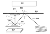
本発明のさらなる様相は、マイクロミラーを駆動するための磁気アクチュエータを製作することである。図8には、本発明による磁気アクチュエータと磁束ガイドシールドとを有する2ミラーシステムの構造が示されている。光ビーム110を送出するレーザ100の形態の光源が図示されている。光ビーム110は第1ミラー200によって反射される。ミラー200は本発明によれば磁気的に駆動されるものであり、マグネットヨーク210、磁気駆動されるミラーエレメント220および磁束ガイドシールド230を有している。その後、光ビーム110は駆動される第2ミラー300によって反射される。可動ミラーは、投影面に2次元的な光パターンが書き込まれるように、光ビーム110を反射する。これにより、例えば結像光学系またはいわゆる光学式2Dスキャナが実現される。
A further aspect of the present invention is to fabricate a magnetic actuator for driving the micromirror. FIG. 8 shows the structure of a two-mirror system having a magnetic actuator and a flux guide shield according to the present invention. A light source in the form of a
図8に示されているように2ミラー装置を前提とすれば、第1ミラーの漂遊磁場をマグネットヨークの開放側に向かって低減させることができる。これは、向かい側のプリント基板400上、第1ミラーの回転軸に対して垂直な回転軸を有する第2ミラーの箇所に、遮蔽プレートの形態の磁束ガイド部材230が固定されていることによって為される。この磁束ガイド部材230は、例えば漂遊磁場を感知する電子素子500が存在する領域に磁力線が出るのを妨げる。スペーサ27は、マグネットヨークとシールド230とが磁力によって相互に引き寄せ合うのを妨げる。
As shown in FIG. 8, assuming a two-mirror device, the stray magnetic field of the first mirror can be reduced toward the open side of the magnet yoke. This is done by fixing a magnetic
Claims (9)
前記プレート(3)は主延在面を有しており、
前記回転軸(4)は前記主延在面に平行であり、
前記プレート(3)は前記主延在面に平行に少なくとも1つの導体ループ(10,10a,10b)を有しており、
前記マグネットヨークは、磁束をガイドするU字形レール(1)と、U字形開口部に対して垂直な磁化方向を有する硬磁石(2)とを有しており、
前記マグネットヨークと前記プレート(3)は、前記マグネットヨークの開口部が前記プレート(3)の主延在面の方を向くように、互いに向き付けられており、
磁束をガイドする前記U字形レール(1)は、前記第1回転軸(4)と平行な主延在方向を有しており、
前記プレート(3)は前記少なくとも1つの導体ループ(10,10a,10b)への通電により前記少なくとも1つの回転軸(4)回りに振れる、ことを特徴とする磁気アクチュエータ。 In a magnetic actuator comprising a plate (3) rotatably supported about at least one first rotation axis (4) and a magnet yoke disposed under the plate (3),
The plate (3) has a main extending surface;
The rotation axis (4) is parallel to the main extending surface;
The plate (3) has at least one conductor loop (10, 10a, 10b) parallel to the main extending surface;
The magnet yoke has a U-shaped rail (1) for guiding magnetic flux, and a hard magnet (2) having a magnetization direction perpendicular to the U-shaped opening,
The magnet yoke and the plate (3) are oriented to each other so that the opening of the magnet yoke faces the main extending surface of the plate (3),
The U-shaped rail (1) for guiding magnetic flux has a main extending direction parallel to the first rotating shaft (4),
The magnetic actuator according to claim 1, wherein the plate (3) swings around the at least one rotating shaft (4) by energizing the at least one conductor loop (10, 10a, 10b).
Applications Claiming Priority (2)
| Application Number | Priority Date | Filing Date | Title |
|---|---|---|---|
| DE102010062591.4 | 2010-12-08 | ||
| DE102010062591A DE102010062591A1 (en) | 2010-12-08 | 2010-12-08 | Magnetic actuator |
Publications (2)
| Publication Number | Publication Date |
|---|---|
| JP2012125145A true JP2012125145A (en) | 2012-06-28 |
| JP6053277B2 JP6053277B2 (en) | 2016-12-27 |
Family
ID=45955515
Family Applications (1)
| Application Number | Title | Priority Date | Filing Date |
|---|---|---|---|
| JP2011269187A Active JP6053277B2 (en) | 2010-12-08 | 2011-12-08 | Magnetic actuator and micromirror and mirror system using the same |
Country Status (5)
| Country | Link |
|---|---|
| US (1) | US10690906B2 (en) |
| JP (1) | JP6053277B2 (en) |
| CN (1) | CN102570766B (en) |
| DE (1) | DE102010062591A1 (en) |
| IT (1) | ITMI20112171A1 (en) |
Cited By (5)
| Publication number | Priority date | Publication date | Assignee | Title |
|---|---|---|---|---|
| JP2016512654A (en) * | 2013-03-12 | 2016-04-28 | コーニンクレッカ フィリップス エヌ ヴェKoninklijke Philips N.V. | U-shaped magnet for biosensor |
| JPWO2015092907A1 (en) * | 2013-12-19 | 2017-03-16 | パイオニア株式会社 | Drive device |
| JP2018128700A (en) * | 2018-05-09 | 2018-08-16 | パイオニア株式会社 | Drive device |
| JP2020092594A (en) * | 2020-01-17 | 2020-06-11 | パイオニア株式会社 | Drive device |
| JP2022033852A (en) * | 2020-01-17 | 2022-03-02 | パイオニア株式会社 | Drive device |
Families Citing this family (8)
| Publication number | Priority date | Publication date | Assignee | Title |
|---|---|---|---|---|
| DE102010064218A1 (en) | 2010-12-27 | 2012-06-28 | Robert Bosch Gmbh | Magnetically driven micromirror |
| DE102011089514B4 (en) | 2011-12-22 | 2022-09-01 | Robert Bosch Gmbh | Micro mirror and 2 mirror system |
| WO2014063737A1 (en) | 2012-10-25 | 2014-05-01 | Lemoptix Sa | A mems device |
| DE102014211546B4 (en) | 2014-06-17 | 2022-08-25 | Robert Bosch Gmbh | MICROSMIRROR ARRANGEMENT |
| RU2639609C2 (en) * | 2016-04-05 | 2017-12-21 | Михаил Викторович Яковлев | Control method by laser beam |
| WO2017194051A1 (en) * | 2016-05-07 | 2017-11-16 | Otto-Von-Guericke-Universität Magdeburg, Ttz Patentwesen | Operative assistance system for a magnetic resonance tomograph |
| CN111327536A (en) * | 2020-03-23 | 2020-06-23 | 杭州半联贸易有限公司 | Internet is with stabilising arrangement who guarantees router signal |
| DE102021204467A1 (en) | 2021-05-04 | 2022-11-10 | Robert Bosch Gesellschaft mit beschränkter Haftung | Micromechanical vibration system |
Citations (6)
| Publication number | Priority date | Publication date | Assignee | Title |
|---|---|---|---|---|
| JP2005266713A (en) * | 2004-03-22 | 2005-09-29 | Hitachi Cable Ltd | Optical switch |
| JP2007304624A (en) * | 2007-07-27 | 2007-11-22 | Ricoh Co Ltd | Polygon mirror machining method, polygon scanner, and optical scanner |
| JP2008076569A (en) * | 2006-09-19 | 2008-04-03 | Seiko Epson Corp | Actuator, optical scanner, and image forming apparatus |
| JP2009089501A (en) * | 2007-09-28 | 2009-04-23 | Nippon Signal Co Ltd:The | Planar electromagnetic actuator |
| JP2009109778A (en) * | 2007-10-31 | 2009-05-21 | Hitachi Metals Ltd | Mirror device |
| JP2009265479A (en) * | 2008-04-28 | 2009-11-12 | Victor Co Of Japan Ltd | Optical deflector and method of driving the same |
Family Cites Families (19)
| Publication number | Priority date | Publication date | Assignee | Title |
|---|---|---|---|---|
| KR100343219B1 (en) * | 1995-02-25 | 2002-11-23 | 삼성전기주식회사 | Apparatus for driving mirror |
| JP2987750B2 (en) | 1995-05-26 | 1999-12-06 | 日本信号株式会社 | Planar type electromagnetic actuator |
| US6188504B1 (en) * | 1996-06-28 | 2001-02-13 | Olympus Optical Co., Ltd. | Optical scanner |
| GB2384060B (en) * | 2000-08-27 | 2004-12-15 | Corning Intellisense Corp | Magnetically actuated micro-electro-mechanical apparatus |
| US6388789B1 (en) * | 2000-09-19 | 2002-05-14 | The Charles Stark Draper Laboratory, Inc. | Multi-axis magnetically actuated device |
| US7071594B1 (en) * | 2002-11-04 | 2006-07-04 | Microvision, Inc. | MEMS scanner with dual magnetic and capacitive drive |
| DE602004006284T2 (en) | 2003-07-14 | 2008-01-03 | Koninklijke Philips Electronics N.V. | laser beam scanner |
| JP4729289B2 (en) * | 2003-12-04 | 2011-07-20 | オリンパス株式会社 | Optical deflector |
| JP2005173436A (en) | 2003-12-15 | 2005-06-30 | Canon Inc | Optical deflector |
| US7482730B2 (en) | 2004-02-09 | 2009-01-27 | Microvision, Inc. | High performance MEMS scanner |
| US7859167B2 (en) | 2004-03-08 | 2010-12-28 | Panasonic Corporation | Micro actuator having tilt and vertical displacement and device having such micro actuator |
| WO2006035378A1 (en) | 2004-09-28 | 2006-04-06 | Koninklijke Philips Electronics N.V. | Two dimensional micro scanner |
| US7471439B2 (en) | 2005-11-23 | 2008-12-30 | Miradia, Inc. | Process of forming a micromechanical system containing an anti-stiction gas-phase lubricant |
| KR100738114B1 (en) | 2006-05-18 | 2007-07-12 | 삼성전자주식회사 | Actuator and two dimensional scanner |
| JP4247254B2 (en) * | 2006-08-08 | 2009-04-02 | マイクロプレシジョン株式会社 | Electromagnetic drive type optical deflection element |
| DE102006038787A1 (en) | 2006-08-18 | 2008-02-21 | Oc Oerlikon Balzers Ag | Mirror drive for projection systems |
| JP4928301B2 (en) * | 2007-02-20 | 2012-05-09 | キヤノン株式会社 | Oscillator device, driving method thereof, optical deflector, and image display device using optical deflector |
| DE102008042346A1 (en) | 2008-09-25 | 2010-04-01 | Robert Bosch Gmbh | Magnetic yoke, micromechanical component and manufacturing method for a magnetic yoke and a micromechanical component |
| US20100141366A1 (en) * | 2008-12-04 | 2010-06-10 | Microvision, Inc. | Magnetically Actuated System |
-
2010
- 2010-12-08 DE DE102010062591A patent/DE102010062591A1/en active Pending
-
2011
- 2011-11-29 IT IT002171A patent/ITMI20112171A1/en unknown
- 2011-11-30 US US13/307,749 patent/US10690906B2/en active Active
- 2011-12-07 CN CN201110404045.1A patent/CN102570766B/en active Active
- 2011-12-08 JP JP2011269187A patent/JP6053277B2/en active Active
Patent Citations (6)
| Publication number | Priority date | Publication date | Assignee | Title |
|---|---|---|---|---|
| JP2005266713A (en) * | 2004-03-22 | 2005-09-29 | Hitachi Cable Ltd | Optical switch |
| JP2008076569A (en) * | 2006-09-19 | 2008-04-03 | Seiko Epson Corp | Actuator, optical scanner, and image forming apparatus |
| JP2007304624A (en) * | 2007-07-27 | 2007-11-22 | Ricoh Co Ltd | Polygon mirror machining method, polygon scanner, and optical scanner |
| JP2009089501A (en) * | 2007-09-28 | 2009-04-23 | Nippon Signal Co Ltd:The | Planar electromagnetic actuator |
| JP2009109778A (en) * | 2007-10-31 | 2009-05-21 | Hitachi Metals Ltd | Mirror device |
| JP2009265479A (en) * | 2008-04-28 | 2009-11-12 | Victor Co Of Japan Ltd | Optical deflector and method of driving the same |
Cited By (5)
| Publication number | Priority date | Publication date | Assignee | Title |
|---|---|---|---|---|
| JP2016512654A (en) * | 2013-03-12 | 2016-04-28 | コーニンクレッカ フィリップス エヌ ヴェKoninklijke Philips N.V. | U-shaped magnet for biosensor |
| JPWO2015092907A1 (en) * | 2013-12-19 | 2017-03-16 | パイオニア株式会社 | Drive device |
| JP2018128700A (en) * | 2018-05-09 | 2018-08-16 | パイオニア株式会社 | Drive device |
| JP2020092594A (en) * | 2020-01-17 | 2020-06-11 | パイオニア株式会社 | Drive device |
| JP2022033852A (en) * | 2020-01-17 | 2022-03-02 | パイオニア株式会社 | Drive device |
Also Published As
| Publication number | Publication date |
|---|---|
| US20120147444A1 (en) | 2012-06-14 |
| DE102010062591A1 (en) | 2012-06-14 |
| JP6053277B2 (en) | 2016-12-27 |
| ITMI20112171A1 (en) | 2012-06-09 |
| US10690906B2 (en) | 2020-06-23 |
| CN102570766A (en) | 2012-07-11 |
| CN102570766B (en) | 2017-10-27 |
Similar Documents
| Publication | Publication Date | Title |
|---|---|---|
| JP6053277B2 (en) | Magnetic actuator and micromirror and mirror system using the same | |
| US6897990B2 (en) | Rocking member apparatus | |
| JP5513834B2 (en) | Lens drive device | |
| JP5720673B2 (en) | Magnetic force type driving device, optical scanning device, and image display device | |
| EP3006395B1 (en) | Drive device | |
| JP2009058930A (en) | Oscillator device, optical deflector and optical instrument using the same | |
| JPWO2008149851A1 (en) | Object detection device | |
| JP4164421B2 (en) | Oscillating device, optical deflector using the oscillating device, image display device using the optical deflector, image forming apparatus, and manufacturing method thereof | |
| JP4968760B1 (en) | Actuator | |
| JP5447411B2 (en) | Two-dimensional optical scanning device and image projection device | |
| JP4144840B2 (en) | Oscillator device, optical deflector, and optical apparatus using optical deflector | |
| JP2010073225A (en) | Objective lens drive unit and disk device using the same | |
| JP2009109778A (en) | Mirror device | |
| JP2010107666A (en) | Optical scanner | |
| JP2014199326A (en) | Driving device | |
| KR20080096731A (en) | Scanning micromirror | |
| JP2009042322A (en) | Oscillating body apparatus, optical deflector and optical equipment using the same | |
| JP2005181395A (en) | Light deflector | |
| JP2006072251A (en) | Planar type actuator | |
| JP2012063656A (en) | Two-dimensional optical scanner, and image projection device using the same | |
| JPH01195417A (en) | Optical beam deflector | |
| JP3775281B2 (en) | Optical pickup | |
| JP2007256554A (en) | Mems device | |
| JP2005148339A (en) | Optical deflector | |
| JP2003029190A (en) | Optical deflector, image display device and imaging device using the same, and method for manufacturing optical deflector |
Legal Events
| Date | Code | Title | Description |
|---|---|---|---|
| A621 | Written request for application examination |
Free format text: JAPANESE INTERMEDIATE CODE: A621 Effective date: 20141208 |
|
| A977 | Report on retrieval |
Free format text: JAPANESE INTERMEDIATE CODE: A971007 Effective date: 20151119 |
|
| A131 | Notification of reasons for refusal |
Free format text: JAPANESE INTERMEDIATE CODE: A131 Effective date: 20151130 |
|
| A601 | Written request for extension of time |
Free format text: JAPANESE INTERMEDIATE CODE: A601 Effective date: 20160229 |
|
| A521 | Request for written amendment filed |
Free format text: JAPANESE INTERMEDIATE CODE: A523 Effective date: 20160527 |
|
| TRDD | Decision of grant or rejection written | ||
| A01 | Written decision to grant a patent or to grant a registration (utility model) |
Free format text: JAPANESE INTERMEDIATE CODE: A01 Effective date: 20161031 |
|
| A61 | First payment of annual fees (during grant procedure) |
Free format text: JAPANESE INTERMEDIATE CODE: A61 Effective date: 20161129 |
|
| R150 | Certificate of patent or registration of utility model |
Ref document number: 6053277 Country of ref document: JP Free format text: JAPANESE INTERMEDIATE CODE: R150 |
|
| R250 | Receipt of annual fees |
Free format text: JAPANESE INTERMEDIATE CODE: R250 |
|
| R250 | Receipt of annual fees |
Free format text: JAPANESE INTERMEDIATE CODE: R250 |
|
| R250 | Receipt of annual fees |
Free format text: JAPANESE INTERMEDIATE CODE: R250 |
|
| R250 | Receipt of annual fees |
Free format text: JAPANESE INTERMEDIATE CODE: R250 |
|
| R250 | Receipt of annual fees |
Free format text: JAPANESE INTERMEDIATE CODE: R250 |