JP2012123732A - Operation item specification device, operation item specification method, operation reference generation device and operation reference generation method - Google Patents
Operation item specification device, operation item specification method, operation reference generation device and operation reference generation method Download PDFInfo
- Publication number
- JP2012123732A JP2012123732A JP2010275894A JP2010275894A JP2012123732A JP 2012123732 A JP2012123732 A JP 2012123732A JP 2010275894 A JP2010275894 A JP 2010275894A JP 2010275894 A JP2010275894 A JP 2010275894A JP 2012123732 A JP2012123732 A JP 2012123732A
- Authority
- JP
- Japan
- Prior art keywords
- specifying
- equipment state
- equipment
- signal sequence
- signal
- Prior art date
- Legal status (The legal status is an assumption and is not a legal conclusion. Google has not performed a legal analysis and makes no representation as to the accuracy of the status listed.)
- Granted
Links
Images


Landscapes
- Testing And Monitoring For Control Systems (AREA)
Abstract
【課題】少ない計算量で、速やかに操作項目の実施順序を特定することができるようにする。
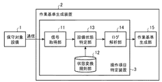
【解決手段】保守対象設備1に対する操作に伴って変化する保守対象設備1の信号系列を取得する信号取得部11と、保守対象設備1の信号系列と設備状態の対応関係を記録している状態変換規則部12と、状態変換規則部12に記録されている対応関係を参照して、信号取得部11により取得された信号系列に対応する設備状態を特定する設備状態特定部13とを設け、ログ解析部14が設備状態特定部13により特定された設備状態の遷移を解析して、保守対象設備1に行われた作業員の操作の項目を検出し、その検出結果から操作項目の実施順序を特定する。
【選択図】図1An execution order of operation items can be quickly identified with a small amount of calculation.
A signal acquisition unit that acquires a signal sequence of a maintenance target facility that changes with an operation on the maintenance target facility, and a state in which a correspondence relationship between the signal sequence of the maintenance target facility and the facility state is recorded A conversion rule unit 12 and a facility state specifying unit 13 for specifying a facility state corresponding to the signal sequence acquired by the signal acquisition unit 11 with reference to the correspondence relationship recorded in the state conversion rule unit 12 are provided. The log analysis unit 14 analyzes the transition of the equipment state specified by the equipment state specifying unit 13 to detect the items of the operation of the worker performed on the maintenance target equipment 1, and the operation item execution order from the detection result Is identified.
[Selection] Figure 1
Description
この発明は、対象設備(例えば、発電所設備)に行われた操作の項目を検出して、その操作項目の実施順序を特定する操作項目特定装置及び操作項目特定方法と、操作項目の実施順序から作業基準を生成する作業基準生成装置及び作業基準生成方法とに関するものである。 The present invention detects an operation item performed on a target facility (for example, a power plant facility), and specifies an operation item specifying device and an operation item specifying method for specifying the execution order of the operation item, and the operation item execution order. The work standard generation device and the work standard generation method for generating a work standard from the above.
例えば、発電所設備などの保守作業では人的作業を必要とする。
しかし、人的作業の場合、作業漏れや抜けが起り易いため、保守作業の内容を確認する機構が必要である。
以下の非特許文献1には、人的作業に伴う機器の信号変化を設備操作ログとして記録する方法が開示されている。
この方法では、予め、実施する保守内容を信号変化で書き下すことで(電子的な作業基準を作成することで)、自動的な作業内容の確認が可能になる。
For example, maintenance work such as power plant equipment requires human work.
However, in the case of human work, work omissions and omissions are likely to occur, so a mechanism for confirming the contents of maintenance work is required.
Non-Patent
In this method, it is possible to automatically confirm the work contents by writing down the contents of the maintenance to be performed in advance with a signal change (by creating an electronic work standard).
ここで、電子化された作業基準は、機器の信号変化を辿ることで、実施された操作項目を類推する技術と、個々の操作項目が実施されるべき順序関係を辿る技術との組合せにより定まるものである。
機器の信号変化を辿る技術では、単純に信号の変化を辿るのではなく、セミマルコフモデルを導入することで、機器の信号変化を辿る方法が述べられている。
即ち、人は同じ作業を実施しても、作業を行う毎に若干の作業の遅速が生じるので、この変化に対処するために、個々の操作項目のそれぞれについて、事前に取得した複数回の設備操作ログからセミマルコフモデルを作成する方法が述べられている。
Here, the computerized work standard is determined by a combination of a technique for inferring the operation items performed by tracing the signal change of the device and a technique for tracing the order relationship in which the individual operation items should be performed. Is.
In the technique of tracing the signal change of the device, a method is described in which the signal change of the device is traced by introducing a semi-Markov model instead of simply tracing the signal change.
In other words, even if a person performs the same work, every time the work is performed, a slight slowdown of the work occurs. Therefore, in order to cope with this change, a plurality of facilities acquired in advance for each operation item. A method for creating a semi-Markov model from operation logs is described.
しかし、保守作業では、作業順序ではなく、確認すべき項目(操作項目)の網羅性が重要であり、作業順序を一意に定めることは難しい。
1つの運用形態として、実施する保守作業の順序を運用規則によって、一意に定めることも考えられる。
ただし、全ての操作項目を網羅して、効率的な操作項目の順序を一意に特定することは困難である。即ち、複数の操作項目を効率的に行う順序は作業員毎に異なるため、操作項目の順序を運用規則で一意に決定すると、作業員の作業効率の低下を招く場合がある。
However, in maintenance work, not the work order but the comprehensiveness of items (operation items) to be confirmed is important, and it is difficult to uniquely determine the work order.
As one operation mode, it may be possible to uniquely determine the order of maintenance work to be performed according to operation rules.
However, it is difficult to uniquely identify an efficient order of operation items covering all operation items. That is, since the order in which a plurality of operation items are efficiently performed differs for each worker, if the order of the operation items is uniquely determined by the operation rules, the work efficiency of the worker may be reduced.
他方の運用形態として、最初に、全ての作業員が、ある1つの作業順序に従う前提で、全作業員の作業基準を生成する。その後、作業員毎に、全作業員の作業基準と当該作業員による実施順序の差異を求めて、その差異によって当該作業基準を修正することも考えられる。
しかし、この場合、差異が生じている箇所を見つけて作業基準を修正する処理を繰り返し実施する必要があるため、実用に耐える全作業員の作業基準が揃うまでには膨大な試行時間を要する。
As the other operation mode, first, all workers generate work standards for all workers on the premise that they follow a certain work order. Thereafter, for each worker, a difference between the work standards of all workers and the execution order by the workers may be obtained, and the work standards may be corrected based on the difference.
However, in this case, since it is necessary to repeatedly perform a process of finding a place where a difference has occurred and correcting the work standard, it takes an enormous trial time until the work standard of all workers who can withstand practical use is obtained.
したがって、保守作業の内容を自動的に確認する機構を導入するには、作業員毎に、個別の作業基準を作成する必要性が高い。
しかし、作業員毎に、個別の作業基準を作成する場合、作業員の違いや、対象設備の違いに応じて、作業基準を作成しなければならず煩雑である。
作成方法の一案として、作業員が対象設備において、基準の保守作業を実施し、その際の設備操作ログを解析して、作業基準を作成する(設備操作ログから作業員毎の作業基準を自動的に作成する)ことが考えられる。
Therefore, in order to introduce a mechanism for automatically confirming the contents of maintenance work, it is highly necessary to create an individual work standard for each worker.
However, when an individual work standard is created for each worker, the work standard must be created according to the difference between the workers and the target equipment, which is complicated.
As a draft of the creation method, the worker performs standard maintenance work on the target equipment, analyzes the equipment operation log at that time, and creates the work standard (the work standard for each worker is determined from the equipment operation log). Automatically created).
ただし、作業員毎の作業基準を作成する際、設備操作ログを解析して、実際に行われた操作項目を検出し、その検出結果から操作項目の実施順序を特定する必要があるが、設備操作ログの中から、操作項目毎に信号列を切り出す単純な解析方法を用いて、操作項目の実施順序を特定する場合、ログ行数N、操作項目数Mに対して、(N×M)のオーダで劇的に計算量が増加するため、設備操作ログの効率的な解析手法を用いる必要がある。 However, when creating a work standard for each worker, it is necessary to analyze the equipment operation log to detect the operation items actually performed and specify the execution order of the operation items from the detection results. When the execution order of operation items is specified using a simple analysis method that extracts a signal string for each operation item from the operation log, (N × M) for the number of log lines N and the number M of operation items Since the amount of calculation increases dramatically on the order of, it is necessary to use an efficient analysis method for equipment operation logs.
従来の作業基準生成方法は以上のように構成されているので、設備操作ログの中から、操作項目毎に信号列を切り出す単純な解析方法を用いて、実際に行われた操作項目を検出している。このため、設備操作ログが多くなると、劇的に計算量が増加してしまって、速やかに操作項目の実施順序を特定することができず、効率的に作業基準を生成することができない課題があった。 Since the conventional work standard generation method is configured as described above, the operation items actually performed are detected from the equipment operation log using a simple analysis method that extracts a signal sequence for each operation item. ing. For this reason, if the facility operation log increases, the amount of calculation increases dramatically, and the execution order of operation items cannot be identified quickly, and the work standard cannot be generated efficiently. there were.
この発明は上記のような課題を解決するためになされたもので、少ない計算量で、速やかに操作項目の実施順序を特定することができる操作項目特定装置及び操作項目特定方法を得ることを目的とする。
また、この発明は、少ない計算量で、速やかに操作項目の実施順序を特定して、効率的に作業基準を生成することができる作業基準生成装置及び作業基準生成方法を得ることを目的とする。
The present invention has been made to solve the above-described problems, and an object thereof is to obtain an operation item specifying device and an operation item specifying method capable of quickly specifying the execution order of operation items with a small amount of calculation. And
Another object of the present invention is to obtain a work standard generation apparatus and a work standard generation method that can quickly specify the execution order of operation items and efficiently generate a work standard with a small amount of calculation. .
この発明に係る操作項目特定装置は、対象設備に対する操作に伴って変化する対象設備の信号系列を取得する信号系列取得手段と、対象設備の信号系列と設備状態の対応関係を記録している対応関係記録手段と、対応関係記録手段に記録されている対応関係を参照して、信号系列取得手段により取得された信号系列に対応する設備状態を特定する設備状態特定手段とを設け、実施順序特定手段が設備状態特定手段により特定された設備状態の遷移を解析して、対象設備に行われた操作の項目を検出し、その検出結果から操作項目の実施順序を特定するようにしたものである。 The operation item specifying device according to the present invention includes a signal sequence acquisition unit that acquires a signal sequence of a target facility that changes in accordance with an operation on the target facility, and a correspondence that records a correspondence relationship between the signal sequence of the target facility and the facility state. A facility recording means and a facility state identifying means for identifying a facility state corresponding to the signal sequence acquired by the signal sequence acquiring means with reference to the correspondence recorded in the correspondence recording means are provided, and the execution order is specified. The means analyzes the transition of the equipment state specified by the equipment state specifying means, detects the operation items performed on the target equipment, and specifies the execution order of the operation items from the detection result. .
この発明によれば、対象設備に対する操作に伴って変化する対象設備の信号系列を取得する信号系列取得手段と、対象設備の信号系列と設備状態の対応関係を記録している対応関係記録手段と、対応関係記録手段に記録されている対応関係を参照して、信号系列取得手段により取得された信号系列に対応する設備状態を特定する設備状態特定手段とを設け、実施順序特定手段が設備状態特定手段により特定された設備状態の遷移を解析して、対象設備に行われた操作の項目を検出し、その検出結果から操作項目の実施順序を特定するように構成したので、少ない計算量で、速やかに操作項目の実施順序を特定することができる効果がある。 According to this invention, the signal sequence acquisition unit that acquires the signal sequence of the target facility that changes in accordance with the operation on the target facility, the correspondence recording unit that records the correspondence between the signal sequence of the target facility and the facility state, An equipment state specifying means for specifying the equipment state corresponding to the signal sequence acquired by the signal series acquisition means with reference to the correspondence recorded in the correspondence relation recording means, and the execution order specifying means is the equipment status. By analyzing the transition of the equipment state specified by the specifying means, detecting the operation items performed on the target equipment, and specifying the execution order of the operation items from the detection results, it is possible to reduce the amount of calculation There is an effect that the execution order of the operation items can be quickly identified.
実施の形態1.
図1はこの発明の実施の形態1による作業基準生成装置を示す構成図である。
図1において、保守対象設備1は例えば保守を必要とする発電設備などが該当し、例えば、通信ケーブル、LAN、インターネットなどの通信回線を通じて、作業基準生成装置2と接続されており、操作に伴って変化する保守対象設備1の信号系列が作業基準生成装置2に伝送される。
作業基準生成装置2は作業員が保守対象設備1に行っている操作の項目を検出して、その操作項目の実施順序を特定する操作項目特定装置3を内蔵しており、操作項目特定装置3により特定された操作項目の実施順序から作業基準を生成する処理を実施する。
FIG. 1 is a block diagram showing a work reference generation apparatus according to
In FIG. 1, the
The work
操作項目特定装置3の信号取得部11は通信回線に対するインタフェース機能を有するネットワーク機器(例えば、LANカード、モデム、無線機など)などから構成されており、作業員の操作に伴って変化する保守対象設備1の信号系列(例えば、発電機の回転数、出力電力などを示す信号)を取得する処理を実施する。なお、信号取得部11は信号系列取得手段を構成している。
操作項目特定装置3の状態変換規則部12は例えばハードディスクやRAMなどのデータ記録装置から構成されており、保守対象設備1の信号系列と設備状態の対応関係を記録しているテーブルを格納している。なお、状態変換規則部12は対応関係記録手段を構成している。
The
The state
操作項目特定装置3の設備状態特定部13は例えばCPUを実装している半導体集積回路、あるいは、ワンチップマイコンなどから構成されており、状態変換規則部12に記録されている対応関係を参照して、信号取得部11により取得された信号系列に対応する設備状態を特定する処理を実施する。なお、設備状態特定部13は設備状態特定手段を構成している。
The equipment
操作項目特定装置3のログ解析部14は例えばCPUを実装している半導体集積回路、あるいは、ワンチップマイコンなどから構成されており、設備状態特定部13により特定された設備状態の遷移を解析して、保守対象設備1に行われた作業員の操作項目を検出し、その検出結果から操作項目の実施順序を特定する処理を実施する。
即ち、ログ解析部14は各種の操作項目に対応する設備状態の遷移パターンを記憶しており、設備状態特定部13により特定された設備状態の遷移を解析して、複数の遷移パターンの中から、その設備状態の遷移を表している遷移パターンを検索し、その遷移パターンに対応する操作項目が保守対象設備1に行われた作業員の操作項目であると認定して、作業員の操作項目の実施順序を特定する処理を実施する。
なお、ログ解析部14は実施順序特定手段を構成している。
The
That is, the
The
作業基準生成部15は例えばCPUを実装している半導体集積回路、あるいは、ワンチップマイコンなどから構成されており、ログ解析部14により特定された操作項目の実施順序と、作業員に実施された操作項目の内容を示す作業基準を生成する処理を実施する。なお、作業基準生成部15は作業基準生成手段を構成している。
The work
図1の例では、作業基準生成装置の構成要素である信号取得部11、状態変換規則部12、設備状態特定部13、ログ解析部14及び作業基準生成部15のそれぞれが専用のハードウェアで構成されているものを想定しているが、作業基準生成装置がコンピュータで構成される場合、信号取得部11、状態変換規則部12、設備状態特定部13、ログ解析部14及び作業基準生成部15の処理内容を記述しているプログラムをコンピュータのメモリに格納し、当該コンピュータのCPUが当該メモリに格納されているプログラムを実行するようにしてもよい。
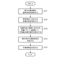
図2はこの発明の実施の形態1による作業基準生成装置の処理内容(作業基準生成方法)を示すフローチャートである。
In the example of FIG. 1, each of the
FIG. 2 is a flowchart showing the processing contents (work standard generation method) of the work standard generation apparatus according to
この実施の形態1では、説明の便宜上、保守対象設備1に対する保守作業として、作業員が3つの操作項目W1,W2,W3を行うものとして説明する。
ただし、操作項目W1,W2,W3の実施順序は、作業員の違いや保守対象設備1の違いに応じて変化する。
例えば、作業員Aであれば、操作項目W2→W1→W3の順序で実施し(図3を参照)、作業員Bであれば、操作項目W3→W2→W1の順序で実施する(図4を参照)ことも考えられる。
したがって、作業員の違いや保守対象設備1の違いに応じた作業基準を生成するには、各作業者による操作項目の実施順序を特定する必要がある。
In the first embodiment, for convenience of explanation, it is assumed that an operator performs three operation items W1, W2, and W3 as maintenance work for the
However, the execution order of the operation items W1, W2, and W3 changes according to the difference in the workers and the difference in the
For example, in the case of the worker A, the operation items W2 → W1 → W3 are executed in the order (see FIG. 3), and in the case of the worker B, the operation items W3 → W2 → W1 are executed (in FIG. 4). See also).
Therefore, in order to generate a work standard according to a difference in workers or a difference in
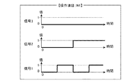
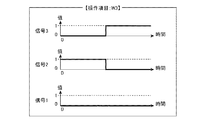
この実施の形態1では、作業員による操作項目W1,W2,W3の設備操作ログとして、3つの信号1、信号2、信号3が得られるものとする。
図5は操作項目W1が行われた場合の保守対象設備1の信号系列(信号1、信号2、信号3)の変化を示す説明図である。
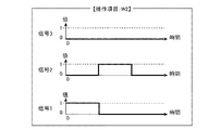
また、図6は操作項目W2が行われた場合の保守対象設備1の信号系列(信号1、信号2、信号3)の変化を示す説明図である。
また、図7は操作項目W3が行われた場合の保守対象設備1の信号系列(信号1、信号2、信号3)の変化を示す説明図である。
In the first embodiment, it is assumed that three
FIG. 5 is an explanatory diagram showing changes in the signal sequence (
FIG. 6 is an explanatory diagram showing changes in the signal sequence (
FIG. 7 is an explanatory diagram showing changes in the signal sequence (
この実施の形態1では、作業員による操作項目W1,W2,W3の全てが既知であり、図5〜図7に示すように、操作項目W1,W2,W3が行われた場合の保守対象設備1の信号系列(信号1、信号2、信号3)の変化も既知である。
ただし、保守対象設備1の信号系列の変化の状態は、図5〜図7に示すように、操作項目毎に異なる。
In the first embodiment, all the operation items W1, W2, and W3 by the worker are known, and as shown in FIGS. 5 to 7, the maintenance target equipment when the operation items W1, W2, and W3 are performed. The change of one signal sequence (
However, the state of change in the signal series of the
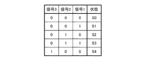
3つの信号1、信号2、信号3の値の組合せを1つの設備状態として扱うとすると、図5〜図7の例では、3つの信号1、信号2、信号3の値の組合せは5通りあるため、図8に示すように、5つの設備状態S0〜S4を定義することができる。
図8では、例えば、信号1の値“1”、信号2の値“0”、信号3の値“0”の場合は設備状態S1と対応付けており、信号1の値“0”、信号2の値“1”、信号3の値“0”の場合は設備状態S2と対応付けている。
操作項目特定装置3の状態変換規則部12では、図8に示すような対応表(保守対象設備1の信号系列と設備状態の対応関係)を記録しているテーブルを格納している。
Assuming that the combination of the three
In FIG. 8, for example, the value “1” of the
The state
図5〜図7及び図8では、説明の簡単化のために、信号系列の値が“0”または“1”である例を示しているが、信号系列の値が多値や連続値であってもよい。
また、保守対象設備1の信号系列が信号1、信号2、信号3の3種類であれば、23=8通りの設備状態を定義することが可能であるが、操作項目W1,W2,W3により出現する設備状態は5通りだけであるため、8通りの設備状態を定義する必要はない。
5 to 7 and 8 show examples in which the value of the signal sequence is “0” or “1” for the sake of simplicity of explanation, the signal sequence value may be a multi-value or a continuous value. There may be.
Further, if the signal sequence of the
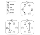
図8の対応表に記述されている5つの設備状態S0〜S4と、図5〜図7に記述されている操作項目W1,W2,W3の信号系列の変化を参照すると、操作項目W1,W2,W3が行われたことによる状態遷移は、図9のように記述することができる。
これにより、操作項目は、設備状態の系列で表現することができる。例えば、操作項目W1は、設備状態S0→S1→S2→S3のように表現することができ、操作項目W2は、設備状態S1→S2→S0のように表現することができる。
したがって、設備状態をアルファベットと見なすと(例えば、操作項目W1の場合:W1=(S0,S1,S2,S3))、操作項目W1,W2,W3の各々を文字列と見なすことができる。
Referring to changes in the signal sequence of the five equipment states S0 to S4 described in the correspondence table of FIG. 8 and the operation items W1, W2, and W3 described in FIGS. 5 to 7, the operation items W1, W2 , W3 can be described as shown in FIG.
Thereby, an operation item can be expressed by the series of equipment states. For example, the operation item W1 can be expressed as equipment state S0 → S1 → S2 → S3, and the operation item W2 can be expressed as equipment state S1 → S2 → S0.
Therefore, when the equipment state is regarded as an alphabet (for example, in the case of the operation item W1: W1 = (S0, S1, S2, S3)), each of the operation items W1, W2, and W3 can be regarded as a character string.
このため、設備操作ログから作業項目の実施順序を特定する問題は、設備操作ログとして与えられたアルファベットの系列から、操作項目W1,W2,W3に対応する単語(設備状態の系列)を検出する問題に置き換えることが可能になる。そのため、文字列の検索問題と対応付けて解くことができる。
そこで、この実施の形態1では、ソフトウェア処理であっても、並列的に単語検索を実現できる高速な文字列検索アルゴリズムであるAho−CorasiCk(AC)法をログ解析部14に導入し、ログ解析部14がAC法を用いて、作業者の作業項目を検出して、その作業項目の実施順序を特定するものとする。
AC法は、以下の非特許文献2に開示されている。
[非特許文献2]
Alfred V. Aho, Margaret J. CorasiCk ”EffiCient String MatChing: An Aid to BibliographiC SearCh”, Comm. ACM, 1975.
Therefore, the problem of specifying the execution order of work items from the equipment operation log is to detect words (equipment state series) corresponding to the operation items W1, W2, and W3 from the alphabetical series given as the equipment operation log. It becomes possible to replace it with a problem. Therefore, it can be solved in association with the character string search problem.
Therefore, in the first embodiment, the Aho-CorasiCk (AC) method, which is a high-speed character string search algorithm that can realize word search in parallel even in software processing, is introduced into the
The AC method is disclosed in
[Non-Patent Document 2]
Alfred V.V. Aho, Margaret J. et al. CorasiCk “EffiCient String MatChing: An Aid to BibliographyC SeaCh”, Comm. ACM, 1975.
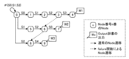
この実施の形態1では、AC法によるトライ(trie)木を生成するため、操作項目W1,W2,W3に対応する辞書パターンを作成する。
即ち、W1=(S0,S1,S2,S3)、W2=(S1,S2,S0)、W3=(SS2,S4)を作成する。
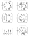
操作項目W1,W2,W3に対応する辞書パターンから、AC法によりトライ木を生成すると図10のようになる。
In the first embodiment, a dictionary pattern corresponding to the operation items W1, W2, and W3 is created in order to generate a trie tree by the AC method.
That is, W1 = (S0, S1, S2, S3), W2 = (S1, S2, S0), and W3 = (SS2, S4) are created.
When a trie tree is generated by the AC method from the dictionary pattern corresponding to the operation items W1, W2, and W3, the result is as shown in FIG.
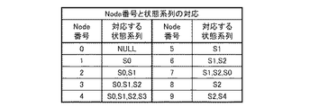
トライ木を用いる設備操作ログの解析動作は後述するが、図10の各Nodeに対応する設備状態の系列は図11のようになる。
図11の例では、Node番号“4”が操作項目W1に係る設備状態の系列に対応し、Node番号“7”が操作項目W2に係る設備状態の系列に対応し、Node番号“9”が操作項目W3に係る設備状態の系列に対応している。
The analysis operation of the facility operation log using the trie tree will be described later, but the series of facility states corresponding to each Node in FIG. 10 is as shown in FIG.
In the example of FIG. 11, the node number “4” corresponds to the equipment state series related to the operation item W1, the node number “7” corresponds to the equipment state series related to the operation item W2, and the node number “9” is set to This corresponds to the equipment state series related to the operation item W3.
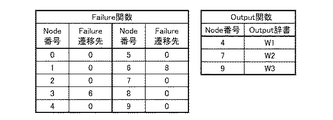
図10に示しているAC法によるトライ木は、図12に示すようなFailure関数とOutput関数を伴っている。
Output関数は、操作項目として意味がある設備状態の系列を検出したときに、出力を伴うNode番号と、その出力内容を示すものである。
Node番号“4”は操作項目W1に対応し、Node番号“7”は操作項目W2に対応し、Node番号“9”は操作項目W3に対応しているため、各々のNodeは対応している操作項目を出力する。
The trie tree by the AC method shown in FIG. 10 is accompanied by a failure function and an output function as shown in FIG.
The Output function indicates a Node number accompanied by an output and the output contents when a series of equipment states that are meaningful as operation items is detected.
Since the node number “4” corresponds to the operation item W1, the node number “7” corresponds to the operation item W2, and the node number “9” corresponds to the operation item W3, each node corresponds. Output operation items.
また、Failure関数は、あるNodeが期待する入力を得られない場合に遷移するNode先を示すものである。
例えば、3番のNodeは、4番のNodeに遷移するために、設備状態S3の入力を期待しているが、入力された設備状態がS3以外である場合、6番のNodeに遷移する(図10において、点線を参照)。
その理由は、3番のNodeは、図11に示すように、設備状態の系列(S0,S1,,S2)に対応しており、次に設備状態S3が入力されれば、操作項目W1に対応する辞書パターンと一致するが、次に設備状態S3が入力されなくても、6番のNodeに対応する設備状態の系列(S1,S2)と同じ系列(S1,S2)を既に検出しているためである。
したがって、入力された設備状態がS3以外である場合、6番のNodeと見なして、入力された設備状態を評価する。
このFailure関数により、意味のある設備状態の系列を効率よく検出することができる。
なお、AC法がソフトウェア処理であっても、並列的に単語検索が実現できる特性は、Failure関数によるものである。
The Failure function indicates a node destination to which a transition is made when an input expected by a certain node cannot be obtained.
For example, the No. 3 node expects an input of the equipment state S3 in order to make a transition to the No. 4 Node, but when the inputted equipment state is other than S3, it makes a transition to the No. 6 Node ( (See dotted line in FIG. 10).
The reason is that the third node corresponds to the equipment status sequence (S0, S1, S2) as shown in FIG. 11, and if the equipment status S3 is input next, the operation item W1 is displayed. Although it matches the corresponding dictionary pattern, the same sequence (S1, S2) as the sequence (S1, S2) of the facility status corresponding to the 6th Node has already been detected even if the facility status S3 is not input next. Because it is.
Therefore, when the input equipment state is other than S3, it is regarded as the sixth node and the input equipment state is evaluated.
By this Failure function, a meaningful series of equipment states can be detected efficiently.
Even if the AC method is software processing, the characteristics that can realize word search in parallel are due to the failure function.
次に動作について説明する。
ただし、ここでは、作業員Cが操作を行うものとする。
まず、操作項目特定装置3の信号取得部11は、作業員Cの操作に伴って変化する保守対象設備1の信号系列(信号1、信号2、信号3)を取得する(ステップST1)。
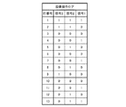
ここでは、説明の便宜上、設備操作ログとして、図13に示すような信号系列(信号1、信号2、信号3)が取得されるものとする。
信号取得部11は、図13に示すような信号系列(信号1、信号2、信号3)の取得が完了するまで取得済みの信号系列を保持し、作業員Cの操作が完了した時点で、取得済みの信号系列(図13の信号系列)を設備状態特定部13に出力する。
Next, the operation will be described.
However, it is assumed here that the operator C performs the operation.
First, the
Here, for convenience of explanation, it is assumed that a signal sequence (
The
設備状態特定部13は、信号取得部11から保守対象設備1の信号系列(信号1、信号2、信号3)を受けると、状態変換規則部12に記録されている対応関係(図8の対応表)を参照して、その信号系列に対応する設備状態を特定する(ステップST2)。
例えば、信号1の値“1”、信号2の値“0”、信号3の値“0”であれば、設備状態がS1であると特定し、信号1の値“0”、信号2の値“1”、信号3の値“0”であれば、設備状態がS2であると特定する。
図14は設備状態特定部13により特定された設備状態の系列(信号系列から設備状態の系列への変換結果)を示す説明図である。
図8の対応表には、操作項目W1,W2,W3により出現しない設備状態は記録されていないので、例えば、信号1の値“0”、信号2の値“1”、信号3の値“1”があるような場合には設備状態を特定することができず、変換後の設備操作ログには“N/A”が記述される。
When the equipment
For example, if the value of
FIG. 14 is an explanatory diagram showing a series of equipment states (results of conversion from a signal series to a series of equipment states) specified by the equipment
In the correspondence table of FIG. 8, equipment states that do not appear due to the operation items W1, W2, and W3 are not recorded. For example, the value “0” of the
ログ解析部14は、設備状態特定部13から変換後の設備操作ログを1行受ける毎(設備状態特定部13が設備状態を1つ特定する毎)に、AC法を用いて、その設備状態の遷移に対応する辞書パターンを探索することで、作業員Cの操作項目を検出する(ステップST3)。
図15はAC法によるログ解析を示す説明図である。
以下、図15を参照しながら、ログ解析部14の処理内容を具体的に説明する。
Each time the
FIG. 15 is an explanatory diagram showing log analysis by the AC method.
Hereinafter, the processing content of the
初期状態では、0番のNodeに滞在しているが、設備状態特定部13から行番号1,2の設備状態N/Aを受けても、期待していない入力であるため、0番のNodeから他のNodeに遷移せずに、0番のNodeの滞在を継続する。
次に、設備状態特定部13から行番号3の設備状態S0を受けると、1番のNodeに遷移する。
次に、設備状態特定部13から行番号4,5の設備状態S1,S2を受けると、2番のNodeに遷移してから、3番のNodeに遷移する。
In the initial state, the node stays at the node No. 0. However, even if the facility state N / A of the
Next, when the equipment state S0 of the
Next, when the facility states S1 and S2 of the
3番Nodeでは、設備状態S3の入力を期待するが、設備状態特定部13から受ける行番号6の設備状態がS0(設備状態S3以外の設備状態)であるため、図12のFailure関数によって、遷移先が6番のNodeであることを認識し、6番のNodeに遷移する。
この時点で、探索済みの設備状態の系列は、図11にしたがって、(S0,S1,S2)から(S1,S2)になる。
6番のNodeに遷移すると、再度、設備状態特定部13から出力された行番号6の設備状態S0を評価する。
6番のNodeでは、設備状態S0の入力を期待しているので、7番のNodeに遷移する。
In the third node, input of the equipment state S3 is expected, but since the equipment state of the
At this time, the searched equipment state sequence is changed from (S0, S1, S2) to (S1, S2) according to FIG.
If it changes to 6th Node, equipment state S0 of the
Since the node No. 6 expects the input of the equipment state S0, it transitions to the node No. 7.
7番のNodeに遷移すると、図12のOutput関数によって、Output辞書に登録されている操作項目W2=(S1,S2,S0)を出力する。
これにより、操作項目W2が検出されたので、再度、0番のNodeに戻り、設備操作ログの解析を継続する。
When transitioning to the seventh node, the operation item W2 = (S1, S2, S0) registered in the output dictionary is output by the output function of FIG.
Thereby, since operation item W2 was detected, it returns to No. 0 Node again and the analysis of an equipment operation log is continued.
次に、設備状態特定部13から行番号7,8の設備状態S1,S2を受けると、5番のNodeに遷移してから、6番のNodeに遷移する。
6番のNodeでは、設備状態S0の入力を期待するが、設備状態特定部13から受ける行番号9の設備状態がS4(設備状態S0以外の設備状態)であるため、図12のFailure関数によって、遷移先が8番のNodeであることを認識し、8番のNodeに遷移する。
この時点で、探索済みの設備状態の系列は、図11にしたがって、(S1,S2)から(S2)になる。
8番のNodeに遷移すると、再度、設備状態特定部13から出力された行番号9の設備状態S4を評価する。
8番のNodeでは、設備状態S4の入力を期待しているので、9番のNodeに遷移する。
Next, when receiving the equipment states S1 and S2 of the
In the sixth node, input of the equipment state S0 is expected, but the equipment state of the
At this point in time, the searched equipment state sequence is changed from (S1, S2) to (S2) according to FIG.
If it changes to 8th Node, equipment state S4 of the
Since the node No. 8 expects the input of the equipment state S4, it transitions to the node No. 9.
9番のNodeに遷移すると、図12のOutput関数によって、Output辞書に登録されている操作項目W3=(S2,S4)を出力する。
これにより、操作項目W3が検出されたので、再度、0番のNodeに戻り、設備操作ログの解析を継続する。
When a transition is made to Node No. 9, the operation item W3 = (S2, S4) registered in the Output dictionary is output by the Output function of FIG.
Thereby, since the operation item W3 was detected, it returns to No. 0 Node again and the analysis of an equipment operation log is continued.
次に、設備状態特定部13から行番号10の設備状態S0を受けると、1番のNodeに遷移する。
次に、設備状態特定部13から行番号11,12の設備状態S1,S2を受けると、2番のNodeに遷移してから、3番のNodeに遷移する。
3番Nodeでは、設備状態S3の入力を期待しており、設備状態特定部13から受ける行番号13の設備状態がS3であるため、4番のNodeに遷移する。
Next, when the equipment state S0 of the
Next, when the facility states S1 and S2 of the
The third node expects an input of the equipment state S3, and since the equipment state of the
4番のNodeに遷移すると、図12のOutput関数によって、Output辞書に登録されている操作項目W1=(S0,S1,S2,S3)を出力する。これにより、操作項目W1が検出される。
ログ解析部14は、操作項目をW2→W3→W1の順序で検出すると、その検出結果から操作項目W1,W2,W3の実施順序が、W2→W3→W1であることを特定する(ステップST4)。
When transitioning to the fourth node, the operation item W1 = (S0, S1, S2, S3) registered in the Output dictionary is output by the Output function of FIG. Thereby, the operation item W1 is detected.
When the
作業基準生成部15は、ログ解析部14が操作項目W1,W2,W3の実施順序(W2→W3→W1)を特定すると、その操作項目の実施順序(W2→W3→W1)と、作業員Cに実施された操作項目W1,W2,W3の内容を示す作業基準を生成する(ステップST5)。
図16は作業基準生成部15により生成された作業基準を示す説明図である。
図16の例では、作業員Cにより実施された操作項目がW1,W2,W3であり、その実施順序がW2→W3→W1であることを表している。
When the
FIG. 16 is an explanatory diagram showing a work standard generated by the work
In the example of FIG. 16, the operation items executed by the worker C are W1, W2, and W3, and the execution order is W2 → W3 → W1.
以上で明らかなように、この実施の形態1によれば、保守対象設備1に対する作業員の操作に伴って変化する保守対象設備1の信号系列を取得する信号取得部11と、保守対象設備1の信号系列と設備状態の対応関係を記録している状態変換規則部12と、状態変換規則部12に記録されている対応関係を参照して、信号取得部11により取得された信号系列に対応する設備状態を特定する設備状態特定部13とを設け、ログ解析部14が設備状態特定部13により特定された設備状態の遷移を解析して、保守対象設備1に行われた作業員の操作の項目を検出し、その検出結果から操作項目の実施順序を特定するように構成したので、少ない計算量で、速やかに操作項目の実施順序を特定することができる効果を奏する。
As is apparent from the above, according to the first embodiment, the
即ち、この実施の形態1によれば、設備操作ログから操作項目の実施順序を特定する問題を、文字列検索処理に対応付けて処理するようにしているので、設備操作ログの中から操作項目毎に信号系列を切り出すための計算量が、ログ解析部14に導入されているAC法によって、ログ行数Nに対して、O(N)のオーダであり、極めて効率的に設備操作ログが解析されている。このため、少ない計算量で、速やかに操作項目の実施順序を特定することができる
That is, according to the first embodiment, the problem of specifying the execution order of operation items from the equipment operation log is processed in association with the character string search process. The amount of calculation for extracting the signal series every time is on the order of O (N) with respect to the number of log lines N by the AC method introduced in the
なお、近年、熟練作業員の定年退職に伴う暗黙知の喪失が様々な分野で問題となっており、設備保守作業の現場では、作業員が有する暗黙知が保守作業の効率化や品質確保に寄与する場合が多い。
本来は明文化されて作業員の間で共有されるべき情報であるが、忙しい作業の合間に自発的に明文化することは難しく、明文化されないまま熟練の作業者が有する暗黙知が定年退職などに伴って、現場から失われることは保守会社にとって大きな損失である。
しかし、この実施の形態1では、設備操作ログから作業員による操作項目の実施順序を自動的に特定するものであるため、熟練の作業員による最適な実施順序(経験的に得られた実施順序)を明文化することに寄与する。
In recent years, loss of tacit knowledge due to retirement of skilled workers has become a problem in various fields, and tacit knowledge possessed by workers helps maintain work more efficiently and ensure quality at the site of equipment maintenance work. Often contributes.
It is originally written information that should be shared among workers, but it is difficult to voluntarily write between busy work, and tacit knowledge held by skilled workers without reciting is retired As a result, the loss from the site is a big loss for the maintenance company.
However, in this
この実施の形態1では、ログ解析部14がACを用いて、設備状態の遷移に対応する辞書パターンを探索するものを示したが、AC法以外の方法で、設備状態の遷移に対応する辞書パターンを探索するようにしてもよい。
AC法以外の方法としては、例えば、Boyer−Moore(BM)法などを用いることができる。
In the first embodiment, the
As a method other than the AC method, for example, a Boyer-Moore (BM) method or the like can be used.
実施の形態2.
上記実施の形態1では、ログ解析部14がACを用いて、設備状態の遷移に対応する辞書パターンを探索するものを示したが、ログ解析部14が、AC法が決定性有限オートマトン(Deterministic Finite Automaton:DFA)化されているAC−DFA法を用いて、設備状態の遷移に対応する辞書パターンを探索するようにしてもよい。
AC−DFA法は、入力に対してNodeの遷移先が一意に定まるようにNode設計されたAC法である。
個々のNodeについて、想定される全ての入力に対してNodeの遷移先が定義されるため、ソフトウェア実装では、AC法よりもメモリ容量を必要とし、ハードウェア実装では、大きな回路規模を必要とする。
しかし、n行の入力に対してn回のNode遷移で解析結果が得られるため、AC法よりも更に高速である。
In the first embodiment, the
The AC-DFA method is an AC method designed for a node so that a node transition destination is uniquely determined with respect to an input.
For each individual Node, Node transition destinations are defined for all possible inputs, so software implementation requires more memory capacity than AC, and hardware implementation requires a larger circuit scale. .
However, since an analysis result can be obtained with n node transitions for n rows of inputs, it is faster than the AC method.
実施の形態3.
保守作業によっては、図9のように一意な状態遷移ができず、図17に示すような遷移を辿る場合も考えられる。
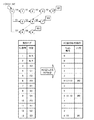
図17に対応する辞書パターンは、図18に示すように、正規表現でしか記述することができず、非決定性有限オートマトン(Nondeterministic Finite Automaton:NFA)になる。
AC法あるいはAC−DFA法では、辞書パターンがDFAで記述される必要があるため、NFA記述された辞書パターンは単純に扱うことができない。
そこで、この実施の形態3では、NFAをDFAに展開することは可能であるため、NFAで記述されている辞書パターンを扱う場合、前処理として、NFAで記述されている辞書パターンをDFA記述に変換する処理を実施してから、上記実施の形態1と同様の処理を実施するようにする。
Depending on the maintenance work, a unique state transition as shown in FIG. 9 cannot be performed, and a transition as shown in FIG. 17 may be followed.
The dictionary pattern corresponding to FIG. 17 can be described only by a regular expression as shown in FIG. 18, and becomes a nondeterministic finite automaton (NFA).
In the AC method or the AC-DFA method, a dictionary pattern needs to be described in DFA, so that a dictionary pattern described in NFA cannot be handled simply.
In this third embodiment, therefore, it is possible to expand NFA to DFA. Therefore, when handling a dictionary pattern described in NFA, the dictionary pattern described in NFA is converted into DFA description as preprocessing. After performing the conversion process, the same process as in the first embodiment is performed.
実施の形態4.
上記実施の形態1〜3では、操作項目W1,W2,W3に対応する設備状態の遷移が異なるものを示したが、複数の操作項目に対応する設備状態の遷移が等しい場合がある。
例えば、操作項目W2に対応する設備状態の遷移と、操作項目W4に対応する設備状態の遷移が等しい場合において、操作項目W2と操作項目W4の間に、出現順序に関する関係(例えば、「操作項目W4は、操作項目W2より先に出現することはない」という関係)があれば、その出現順序に関する関係を考慮して、どの操作項目が行われたかを検出するようにする。
即ち、ログ解析部14は、操作項目W2,W4に対応する設備状態の遷移が得られた場合、未だ操作項目W2を検出していなければ、今回の操作項目はW2であると判断する。
一方、既に操作項目W2を検出していれば、今回の操作項目はW4であると判断する。
これにより、複数の操作項目に対応する設備状態の遷移が等しい場合でも、操作項目を特定することができる。
In the first to third embodiments, the transition of the equipment state corresponding to the operation items W1, W2, and W3 is different, but the transition of the equipment state corresponding to a plurality of operation items may be equal.
For example, when the transition of the equipment state corresponding to the operation item W2 is the same as the transition of the equipment state corresponding to the operation item W4, a relationship related to the appearance order between the operation item W2 and the operation item W4 (for example, “operation item If there is a relationship that “W4 never appears before the operation item W2”), it is determined which operation item has been performed in consideration of the relationship regarding the appearance order.
That is, when the transition of the equipment state corresponding to the operation items W2 and W4 is obtained, the
On the other hand, if the operation item W2 has already been detected, it is determined that the current operation item is W4.
Thereby, even when the transition of the equipment state corresponding to a plurality of operation items is equal, the operation item can be specified.
実施の形態5.
上記実施の形態1〜4では、信号取得部11が、作業員の操作が完了するまで取得済みの信号系列を保持し、作業員の操作が完了した時点で、取得済みの信号系列を設備状態特定部13に出力するものを示したが、保守対象設備1の信号系列が変化する毎に、信号取得部11が、保守対象設備1の信号系列を取得して、その信号系列を設備状態特定部13に出力するようにしてもよい。
In the said Embodiment 1-4, the
なお、本願発明はその発明の範囲内において、各実施の形態の自由な組み合わせ、あるいは各実施の形態の任意の構成要素の変形、もしくは各実施の形態において任意の構成要素の省略が可能である。 In the present invention, within the scope of the invention, any combination of the embodiments, or any modification of any component in each embodiment, or omission of any component in each embodiment is possible. .
1 保守対象設備、2 作業基準生成装置、3 操作項目特定装置、11 信号取得部(信号系列取得手段)、12 状態変換規則部(対応関係記録手段)、13 設備状態特定部(設備状態特定手段)、14 ログ解析部(実施順序特定手段)、15 作業基準生成部(作業基準生成手段)。
DESCRIPTION OF
Claims (9)
Priority Applications (1)
| Application Number | Priority Date | Filing Date | Title |
|---|---|---|---|
| JP2010275894A JP5733965B2 (en) | 2010-12-10 | 2010-12-10 | Operation item identification device, operation item identification method, work standard generation device, and work standard generation method |
Applications Claiming Priority (1)
| Application Number | Priority Date | Filing Date | Title |
|---|---|---|---|
| JP2010275894A JP5733965B2 (en) | 2010-12-10 | 2010-12-10 | Operation item identification device, operation item identification method, work standard generation device, and work standard generation method |
Publications (2)
| Publication Number | Publication Date |
|---|---|
| JP2012123732A true JP2012123732A (en) | 2012-06-28 |
| JP5733965B2 JP5733965B2 (en) | 2015-06-10 |
Family
ID=46505080
Family Applications (1)
| Application Number | Title | Priority Date | Filing Date |
|---|---|---|---|
| JP2010275894A Expired - Fee Related JP5733965B2 (en) | 2010-12-10 | 2010-12-10 | Operation item identification device, operation item identification method, work standard generation device, and work standard generation method |
Country Status (1)
| Country | Link |
|---|---|
| JP (1) | JP5733965B2 (en) |
Cited By (2)
| Publication number | Priority date | Publication date | Assignee | Title |
|---|---|---|---|---|
| JP2022003493A (en) * | 2020-06-23 | 2022-01-11 | 株式会社日立製作所 | Analytical equipment, analysis method and computer program |
| JPWO2023112168A1 (en) * | 2021-12-14 | 2023-06-22 |
-
2010
- 2010-12-10 JP JP2010275894A patent/JP5733965B2/en not_active Expired - Fee Related
Non-Patent Citations (1)
| Title |
|---|
| JPN6014031979; 齊藤 啓太 , 鈴木 清彦 , 小貫 淳史: '作業手順モデルに基づいた実施作業推定手法' 全国大会講演論文集 第72回平成22年(4) , 20100308, 一般社団法人情報処理学会 * |
Cited By (4)
| Publication number | Priority date | Publication date | Assignee | Title |
|---|---|---|---|---|
| JP2022003493A (en) * | 2020-06-23 | 2022-01-11 | 株式会社日立製作所 | Analytical equipment, analysis method and computer program |
| JP7502096B2 (en) | 2020-06-23 | 2024-06-18 | 株式会社日立製作所 | Analysis device, analysis method, and computer program |
| JPWO2023112168A1 (en) * | 2021-12-14 | 2023-06-22 | ||
| JP7687445B2 (en) | 2021-12-14 | 2025-06-03 | 日本電信電話株式会社 | Extraction device, extraction method, and extraction program |
Also Published As
| Publication number | Publication date |
|---|---|
| JP5733965B2 (en) | 2015-06-10 |
Similar Documents
| Publication | Publication Date | Title |
|---|---|---|
| CN108829607B (en) | Software defect prediction method based on convolutional neural network | |
| Kim et al. | Leveraging large language models to improve rest api testing | |
| CN112733156B (en) | Intelligent detection method, system and medium for software vulnerability based on code attribute graph | |
| CN104407872B (en) | How to detect code clones | |
| JP2009099124A (en) | Data construction method and system | |
| CN111898134A (en) | Intelligent contract vulnerability detection method and device based on LSTM and BiLSTM | |
| CN115828180A (en) | A log anomaly detection method based on parsing optimization and temporal convolutional network | |
| CN114528457B (en) | Web fingerprint detection method and related equipment | |
| JP7031627B2 (en) | Analytical equipment, analysis method, and analysis program | |
| JP2011138422A (en) | Device, method and program for detecting behavioral-pattern | |
| CN110007906B (en) | Script file processing method, device and server | |
| CN114039758A (en) | Network security threat identification method based on event detection mode | |
| CN105117771B (en) | A kind of agricultural machinery fault recognition method based on correlation rule directed acyclic graph | |
| CN117574383A (en) | Feature fusion and code visualization technology-based software vulnerability detection model method | |
| CN107704235A (en) | The analytic method of data flowchart, system and storage medium in mathematics library | |
| CN118051370A (en) | Container cloud micro-service performance anomaly root cause positioning method based on large language model | |
| CN117792882A (en) | Communication network fault log analysis method based on large language model assistance | |
| JP2018132965A (en) | Fault analysis program, fault analysis device, and fault analysis method | |
| CN113535594B (en) | Method, device, equipment and storage medium for generating service scene test case | |
| CN118296612A (en) | A source code vulnerability detection method based on sequence and graph dual-channel model | |
| JP5733965B2 (en) | Operation item identification device, operation item identification method, work standard generation device, and work standard generation method | |
| CN116663019B (en) | Source code vulnerability detection method, device and system | |
| CN118333381A (en) | Intelligent construction site construction data analysis method and system based on big data | |
| CN113407495A (en) | SIMHASH-based file similarity determination method and system | |
| AU2020477732B2 (en) | Estimation device, estimation method, and estimation program |
Legal Events
| Date | Code | Title | Description |
|---|---|---|---|
| A621 | Written request for application examination |
Free format text: JAPANESE INTERMEDIATE CODE: A621 Effective date: 20131008 |
|
| A977 | Report on retrieval |
Free format text: JAPANESE INTERMEDIATE CODE: A971007 Effective date: 20140723 |
|
| A131 | Notification of reasons for refusal |
Free format text: JAPANESE INTERMEDIATE CODE: A131 Effective date: 20140805 |
|
| A521 | Request for written amendment filed |
Free format text: JAPANESE INTERMEDIATE CODE: A523 Effective date: 20141001 |
|
| TRDD | Decision of grant or rejection written | ||
| A01 | Written decision to grant a patent or to grant a registration (utility model) |
Free format text: JAPANESE INTERMEDIATE CODE: A01 Effective date: 20150317 |
|
| A61 | First payment of annual fees (during grant procedure) |
Free format text: JAPANESE INTERMEDIATE CODE: A61 Effective date: 20150414 |
|
| R150 | Certificate of patent or registration of utility model |
Ref document number: 5733965 Country of ref document: JP Free format text: JAPANESE INTERMEDIATE CODE: R150 |
|
| R250 | Receipt of annual fees |
Free format text: JAPANESE INTERMEDIATE CODE: R250 |
|
| R250 | Receipt of annual fees |
Free format text: JAPANESE INTERMEDIATE CODE: R250 |
|
| R250 | Receipt of annual fees |
Free format text: JAPANESE INTERMEDIATE CODE: R250 |
|
| R250 | Receipt of annual fees |
Free format text: JAPANESE INTERMEDIATE CODE: R250 |
|
| R250 | Receipt of annual fees |
Free format text: JAPANESE INTERMEDIATE CODE: R250 |
|
| S533 | Written request for registration of change of name |
Free format text: JAPANESE INTERMEDIATE CODE: R313533 |
|
| R350 | Written notification of registration of transfer |
Free format text: JAPANESE INTERMEDIATE CODE: R350 |
|
| R250 | Receipt of annual fees |
Free format text: JAPANESE INTERMEDIATE CODE: R250 |
|
| R250 | Receipt of annual fees |
Free format text: JAPANESE INTERMEDIATE CODE: R250 |
|
| LAPS | Cancellation because of no payment of annual fees |