JP2012123715A - Wireless sensor system - Google Patents
Wireless sensor system Download PDFInfo
- Publication number
- JP2012123715A JP2012123715A JP2010275648A JP2010275648A JP2012123715A JP 2012123715 A JP2012123715 A JP 2012123715A JP 2010275648 A JP2010275648 A JP 2010275648A JP 2010275648 A JP2010275648 A JP 2010275648A JP 2012123715 A JP2012123715 A JP 2012123715A
- Authority
- JP
- Japan
- Prior art keywords
- unit
- time zone
- intermittent reception
- mode
- time
- Prior art date
- Legal status (The legal status is an assumption and is not a legal conclusion. Google has not performed a legal analysis and makes no representation as to the accuracy of the status listed.)
- Granted
Links
Images


Classifications
-
- Y—GENERAL TAGGING OF NEW TECHNOLOGICAL DEVELOPMENTS; GENERAL TAGGING OF CROSS-SECTIONAL TECHNOLOGIES SPANNING OVER SEVERAL SECTIONS OF THE IPC; TECHNICAL SUBJECTS COVERED BY FORMER USPC CROSS-REFERENCE ART COLLECTIONS [XRACs] AND DIGESTS
- Y02—TECHNOLOGIES OR APPLICATIONS FOR MITIGATION OR ADAPTATION AGAINST CLIMATE CHANGE
- Y02D—CLIMATE CHANGE MITIGATION TECHNOLOGIES IN INFORMATION AND COMMUNICATION TECHNOLOGIES [ICT], I.E. INFORMATION AND COMMUNICATION TECHNOLOGIES AIMING AT THE REDUCTION OF THEIR OWN ENERGY USE
- Y02D30/00—Reducing energy consumption in communication networks
- Y02D30/70—Reducing energy consumption in communication networks in wireless communication networks
Landscapes
- Alarm Systems (AREA)
- Mobile Radio Communication Systems (AREA)
Abstract
【課題】電池寿命の短縮を抑えつつ全ての子機のモードが切り換わるまでの時間の短縮を図る。
【解決手段】子機制御部20では、モード切換が行われる予定時間帯における間欠受信周期T1が、非予定時間帯における間欠受信周期T2よりも短い時間に設定されている。そのため、時間帯の区別無しに間欠受信周期がT2に固定されている場合と比較して、モード切換用のスイッチが操作されてから切換後のモードが親機Mの表示部14で表示されるまでに要する時間が短縮される。しかも、予定時間帯のみで間欠受信周期が短縮されているので、間欠受信周期が時間帯の区別無しに短縮される場合に比べて、電池寿命の短縮を抑えることができる。
【選択図】 図1[PROBLEMS] To reduce the time until the mode of all slave units is switched while suppressing the shortening of battery life.
In a slave unit control unit, an intermittent reception cycle T1 in a scheduled time zone in which mode switching is performed is set to a time shorter than an intermittent reception cycle T2 in an unscheduled time zone. Therefore, compared with the case where the intermittent reception period is fixed at T2 without distinguishing the time zone, the mode after switching after the mode switching switch is operated is displayed on the display unit 14 of the main unit M. The time required until is reduced. In addition, since the intermittent reception cycle is shortened only in the scheduled time zone, it is possible to suppress a reduction in battery life as compared with a case where the intermittent reception cycle is shortened without distinction of the time zone.
[Selection] Figure 1
Description
本発明は、無線式センサシステムに関する。 The present invention relates to a wireless sensor system.
従来の無線式センサシステムとして、例えば、特許文献1に記載されているものがある。特許文献1に記載されている無線式センサシステムは、複数のセキュリティセンサ(子機)と、1台の通信装置(親機)とで構成されている。子機は、それぞれに窓の開閉や人の存在などを検知するセンサと、センサによる検知結果を親機に送信したり、親機から送信されるモード切換の制御コマンドを受信する無線通信手段とを有している。また、親機は、子機との間で無線通信を行い、子機から送信される検知結果を受信して警報を発したり、子機を警戒モードと非警戒モードに切り換える。但し、警戒モードとは子機がセンサによる検知結果を親機に送信する機能(センサ機能)を有効とするモードであり、非警戒モードとは前記センサ機能を無効とするモードである。なお、これらの子機は、配線が不要で施工作業が容易であるという無線通信の利点を活かすために電池を電源として動作するように構成されている。また、電池の寿命を延ばすため、各子機では、所定の間欠受信周期毎に受信回路を起動するとともに無線信号が受信されなければ直ちに受信回路を停止させる間欠受信動作が行われている。 An example of a conventional wireless sensor system is described in Patent Document 1. The wireless sensor system described in Patent Document 1 includes a plurality of security sensors (slave devices) and one communication device (master device). Each slave unit has a sensor for detecting opening / closing of a window, the presence of a person, etc., and a wireless communication means for transmitting a detection result by the sensor to the master unit and receiving a mode switching control command transmitted from the master unit. have. Further, the parent device performs wireless communication with the child device, receives a detection result transmitted from the child device, issues an alarm, or switches the child device between a warning mode and a non-warning mode. However, the alert mode is a mode in which the slave unit validates a function (sensor function) for transmitting the detection result of the sensor to the master unit, and the non-alert mode is a mode in which the sensor function is invalidated. In addition, these cordless handsets are configured to operate using a battery as a power source in order to take advantage of the wireless communication that wiring is unnecessary and construction work is easy. In order to extend the life of the battery, each slave unit performs an intermittent reception operation of starting the reception circuit at every predetermined intermittent reception cycle and immediately stopping the reception circuit if no radio signal is received.
この従来例において、親機から制御コマンドを送信して各子機を非警戒モードから警戒モードに切り換える際の動作を簡単に説明する。親機は、モード切換の制御コマンドを子機の間欠受信周期よりも長い送信時間でマルチキャスト(同報)する。各子機は、親機からマルチキャストされる制御コマンドを受信すると間欠受信から常時受信に切り換わる。親機は、制御コマンドをマルチキャストした後、間欠受信周期よりも充分短い送信時間で何れか1台の子機に対して再度モード切換の制御コマンドをユニキャストする。当該子機は、先にマルチキャストされた制御コマンドを受信できていれば常時受信を行っているので、親機から短時間だけユニキャストされる制御コマンドを受信することができる。制御コマンドを受信した子機は、非警戒モードから警戒モードに切り換わるとともに、受信応答(ACK)を親機に返信(ユニキャスト)する。親機は、子機から受信応答を受け取ると、別の子機にモード切換の制御コマンドをユニキャストする。このようにして親機が全ての子機に対して制御コマンドを順次ユニキャストすることにより、全ての子機を確実に警戒モードに切り換えることができる。また、各子機から返信される受信応答を受け取ることにより、親機は、各子機が非警戒モードから警戒モードに切り換わったことが確認できる。なお、親機は、全ての子機が非警戒モードから警戒モードあるいは警戒モードから非警戒モードに切り換わったときにそれを報知(表示)している。 In this conventional example, an operation when a control command is transmitted from the parent device and each child device is switched from the non-warning mode to the warning mode will be briefly described. The master unit multicasts (broadcasts) a mode switching control command with a transmission time longer than the intermittent reception cycle of the slave unit. Each slave unit switches from intermittent reception to constant reception when receiving a multicast control command from the master unit. After multicasting the control command, the master unit unicasts the mode switching control command again to any one slave unit with a transmission time sufficiently shorter than the intermittent reception cycle. Since the slave unit always receives the multicast control command previously received, it can receive the control command unicast from the master unit for a short time. The slave unit that has received the control command switches from the non-alert mode to the alert mode, and returns (unicast) a reception response (ACK) to the master unit. When receiving the reception response from the slave unit, the master unit unicasts a mode switching control command to another slave unit. In this way, the parent device sequentially unicasts the control commands to all the child devices, so that all the child devices can be surely switched to the alert mode. Further, by receiving a reception response returned from each slave unit, the master unit can confirm that each slave unit has been switched from the non-warning mode to the warning mode. The master unit notifies (displays) when all the slave units are switched from the non-warning mode to the warning mode or from the warning mode to the non-warning mode.
ところで、上述した無線式センサシステムが住宅や店舗あるいは事務所などに設置される場合、住人が帰宅した際あるいは従業員が出勤した際に子機が警戒モードから非警戒モードに切り換えられる。また、住人が外出する際あるいは従業員が退勤する際に子機が非警戒モードから警戒モードに切り換えられる。このとき、特許文献1記載の従来例では各子機の間欠受信周期が同期していないので、モード切換の制御コマンドを間欠受信周期よりも長い送信時間で、1回若しくは複数回、マルチキャストしなければならない。その結果、全ての子機が非警戒モードから警戒モード、あるいは警戒モードから非警戒モードに切り換わって親機で報知されるまでに相当の時間を要してしまう。一方、モード切換に要する前記時間を短くするために間欠受信周期を短くしてしまうと、電池の寿命も短くなってしまう。 By the way, when the above-described wireless sensor system is installed in a house, a store, an office, or the like, the slave unit is switched from the warning mode to the non-warning mode when the resident returns home or the employee goes to work. Further, when the resident goes out or the employee leaves the office, the handset is switched from the non-warning mode to the warning mode. At this time, in the conventional example described in Patent Document 1, since the intermittent reception cycle of each slave unit is not synchronized, the mode switching control command must be multicast one or more times with a transmission time longer than the intermittent reception cycle. I must. As a result, it takes a considerable time for all the slave units to switch from the non-warning mode to the warning mode, or from the warning mode to the non-warning mode and be notified by the parent device. On the other hand, if the intermittent reception cycle is shortened in order to shorten the time required for mode switching, the battery life is also shortened.
本発明は、上記課題に鑑みて為されたものであり、電池寿命の短縮を抑えつつ全ての子機のモードが切り換わるまでの時間の短縮を図ることを目的とする。 The present invention has been made in view of the above problems, and an object of the present invention is to shorten the time until the mode of all the slave units is switched while suppressing the shortening of the battery life.
本発明の無線式センサシステムは、親機と、センサ機能を有する複数の子機とを有し、当該子機は、所定の間欠受信周期で無線信号の受信待ちを行うとともに、前記親機から送信されるモード切換の制御コマンドを受信した場合に、前記センサ機能を有効とする警戒モードと前記センサ機能を無効とする非警戒モードを択一的に切り換えてなり、前記モード切換が行われる予定の時間帯における前記間欠受信周期が、当該予定時間帯を除く時間帯における前記間欠受信周期よりも短い時間に設定されることを特徴とする。 The wireless sensor system of the present invention includes a master unit and a plurality of slave units having a sensor function. The slave unit waits for reception of a radio signal at a predetermined intermittent reception cycle, and from the master unit. When the transmitted mode switching control command is received, the mode switching is scheduled to be performed alternatively between the warning mode for enabling the sensor function and the non-warning mode for disabling the sensor function. The intermittent reception cycle in the time zone is set to a time shorter than the intermittent reception cycle in the time zone excluding the scheduled time zone.
この無線式センサシステムにおいて、前記子機は、実際にモード切換が行われた時間の履歴に応じて前記予定時間帯を変更することが好ましい。 In this wireless sensor system, it is preferable that the slave unit changes the scheduled time zone according to a history of time when mode switching is actually performed.
この無線式センサシステムにおいて、前記子機は、前記モード切換の制御コマンドの受信完了時点から一定時間が経過した時点で前記間欠受信周期のカウントを開始することが好ましい。 In this wireless sensor system, it is preferable that the slave unit starts counting the intermittent reception cycle when a predetermined time has elapsed from the completion of reception of the mode switching control command.
本発明の無線式センサシステムは、電池寿命の短縮を抑えつつ全ての子機のモードが切り換わるまでの時間の短縮を図ることができるという効果がある。 The wireless sensor system of the present invention has an effect that it is possible to shorten the time until the mode of all the slave units is switched while suppressing the shortening of the battery life.
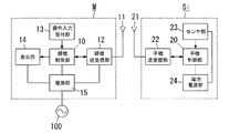
本実施形態の無線式センサシステムは、図2に示すように1台の親機Mと、複数台(図示例では1台)の子機Si(i=1,2,3,…)とで構成されている。 As shown in FIG. 2, the wireless sensor system of the present embodiment includes one master unit M and a plurality of slave units Si (i = 1, 2, 3,...) In the illustrated example. It is configured.
子機Siは、子機制御部20、アンテナ21、子機送受信部22、センサ部23、電池電源部24を備える。子機送受信部22は、例えば、電波法施行規則第6条第4項第3号に規定される「小電力セキュリティシステムの無線局」に準拠して電波を媒体とする無線信号を送受信する。センサ部23は、対象物の存在や量などを検知して電気信号に変換するものであって、例えば、人体から放射される赤外線を焦電素子により検知する人感センサや、窓ガラスに加わる振動を検知する破壊センサ、あるいは火災に伴う煙や熱を検知する火災センサなどがある。子機制御部20はマイクロコントローラ(以下、マイコンと略す。)を主構成要素とし、センサ部23の検知結果(例えば、不審者の侵入や火災の発生など)を示すメッセージを含む無線信号を子機送受信部22から送信させる処理などを行う。電池電源部24は、一次電池あるいは二次電池を電源として子機制御部20、子機送受信部22、センサ部23の動作電源を作成して供給している。これらの子機Siは、電池の消耗を極力防ぐため、後述するように受信動作を常時ではなく間欠的に行う。
The slave unit Si includes a slave
親機Mは、親機制御部10、アンテナ11、親機送受信部12、操作入力受付部13、表示部14、電源部15を備える。親機送受信部12は、例えば、子機送受信部22と同様に、電波法施行規則第6条第4項第3号に規定される「小電力セキュリティシステムの無線局」に準拠して電波を媒体とする無線信号を送受信する。操作入力受付部13は、1乃至複数のスイッチ(例えば、押釦スイッチ)を有し、当該スイッチが操作されることで各スイッチに対応した操作入力を受け付けるとともに当該操作入力に対応した操作信号を親機制御部10に出力する。親機制御部10は、子機制御部20と同様にマイコンを主構成要素とし、後述するように何れかの子機Siから無線信号で送信される検知結果に応じた処理、例えば、不審者の侵入や火災などの異常発生を警報音や警報表示で報知したり、何らかの外部通信手段を経由して遠隔地の通報先へ異常発生を報知する処理などを行う。表示部14は、発光ダイオードなどの発光素子からなり、例えば、後述するように子機Siが警戒モードのときに発光(点灯)し、非警戒モードのときに消光(消灯)して子機Siのモード切換の状態を表示する。電源部15は外部の電源(例えば、商用交流電源100)から給電される交流電力を直流電力に変換して親機制御部10、親機送受信部12、表示部14に供給している。なお、親機Mは外部電源で動作するため、子機Siとは異なり、送信時以外では親機送受信部12が常時受信待ちの状態にある(図1参照)。
Base unit M includes base
なお、親機M及び子機Siには固有の識別符号が割り当てられて各々の制御部10,20が有するメモリに格納されており、当該識別符号によって無線信号の送信先並びに送信元が特定できる。
A unique identification code is assigned to each of the parent device M and the child device Si and stored in the memory of each of the
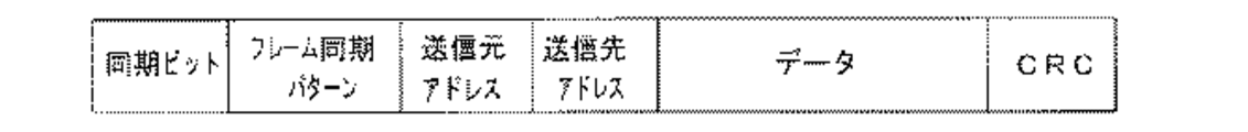
図3は本実施形態の無線式センサシステムで送受信する無線信号のフレームフォーマットを示している。すなわち、1フレームは同期ビット(プリアンブル)、フレーム同期パターン(ユニークワード)、送信先アドレス、送信元アドレス、データ(メッセージ)、CRC符号で構成されている。ここで、送信先アドレスとして識別符号が設定されていれば、当該識別符号が割り当てられている端末(親機M、子機Si)のみが無線信号を受信してメッセージを取得することになる。しかしながら、送信先アドレスとして何れの端末にも割り当てられていない特殊なビット列(例えば、すべてのビットを1としたビット列)が設定された場合、その無線信号が同報(マルチキャスト)されて全ての端末でメッセージが取得される。例えば、モード切換の制御コマンドを含む無線信号は、親機Mから全ての子機Siに同報される。 FIG. 3 shows a frame format of a radio signal transmitted and received by the wireless sensor system of this embodiment. That is, one frame includes a synchronization bit (preamble), a frame synchronization pattern (unique word), a transmission destination address, a transmission source address, data (message), and a CRC code. Here, if an identification code is set as the transmission destination address, only the terminal (master device M, slave device Si) to which the identification code is assigned receives the radio signal and acquires the message. However, when a special bit string (for example, a bit string in which all bits are set to 1) that is not assigned to any terminal is set as a destination address, the radio signal is broadcast (multicast) and all terminals Get the message. For example, a radio signal including a mode switching control command is broadcast from the master unit M to all the slave units Si.
ところで、各子機Siにおいては、上述したように電池電源部24の電池寿命をできるだけ長くするため、無線信号の送信時以外では間欠受信を行っている。すなわち、子機制御部20は、マイコンに内蔵するタイマで所定の間欠受信周期を繰り返しカウントするとともに間欠受信周期のカウントが完了する毎に子機送受信部22を起動して所望の電波(親機Mが送信した無線信号)が受信できるか否かをチェックする。そして、当該電波が捉えられなければ、子機制御部20は直ちに子機送受信部22を停止して待機状態に移行させることで平均消費電力を大幅に低減している。なお、電波の受信チェックは、子機送受信部22から出力される、受信信号強度の大小に比例した直流電圧信号である受信信号強度表示信号(Receiving Signal Strength Indication:RSSI信号)に基づいて子機制御部20が行っている。
By the way, in each handset Si, as described above, in order to make the battery life of the battery
また、各子機Siの子機制御部20は、センサ部23の検知結果(人の存在検知や窓ガラスの破壊検知など)を無線信号で親機Mに送信する動作モード(警戒モード)と、センサ部23の検知結果を無線信号で親機Mに送信しない動作モード(非警戒モード)とが択一的に選択可能であって、親機Mからの指示(制御コマンド)に基づいて警戒モードと非警戒モードを切り換えている。例えば、対象エリア(住宅や店舗あるいは事務所や工場など)内に人(住人あるいは従業員)がいるときは各子機Siが非警戒モードとされ、対象エリア内に人がいないときに各子機Siが警戒モードとされる。なお、子機制御部20は、非警戒モードにおいて、センサ部23を停止するか、あるいはセンサ部23を動作させつつ検知結果を含む無線信号の送信を行わないようにしている。
In addition, the
親機Mの操作入力受付部13にはモード切換用のスイッチが設けられており、当該スイッチが操作されると操作入力受付部13にモード切換の操作入力が受け付けられ、当該操作入力に対応する操作信号が操作入力受付部13から親機制御部10に出力される。親機制御部10は、モード切換の操作信号が入力されると、各子機Siを警戒モード又は非警戒モードに切り換えるための制御コマンドを生成し、当該制御コマンドを含み且つ送信先アドレスにマルチキャスト用のアドレス(ビット列)を設定した無線信号を親機送受信部12から送信させる。
The operation input receiving unit 13 of the base unit M is provided with a mode switching switch. When the switch is operated, the operation input receiving unit 13 receives a mode switching operation input and corresponds to the operation input. An operation signal is output from the operation input receiving unit 13 to the parent
前記無線信号が各子機Siで受信されると、子機制御部20が当該無線信号に含まれる制御コマンドに基づいて警戒モードと非警戒モードを切り換える。さらに子機制御部20は、制御コマンドに対する応答メッセージ(ACKメッセージ)を生成し、当該応答メッセージを含み且つ送信先アドレスに親機Mの識別符号を設定した無線信号を子機送受信部22から送信させる。
When the radio signal is received by each slave unit Si, the slave
親機Mの親機制御部10は、モード切換が正常に行われたことを示す応答メッセージを全ての子機Siから受け取れば、表示部14にモードの切換状態を表示させてモード切換の処理を終了する。
When the base
ここで、各子機Siの子機制御部20においては、モード切換が行われる予定の時間帯(予定時間帯)における間欠受信周期T2が、当該予定時間帯を除く時間帯における間欠受信周期T1よりも短い時間(T1>T2)に設定されている。なお、モード切換が行われる予定時間帯とは、例えば、店舗の開店時刻や事務所の始業時刻よりも1時間早い時刻から開店時刻や始業時刻までの時間帯や、店舗の閉店時刻や事務所の終業時刻から1時間後の時刻までの時間帯などが想定される。なお、子機制御部20は、間欠受信周期をカウントするタイマとは異なる別のタイマで予定時間帯の開始時点及び終了時点を計時(カウント)している。
Here, in the slave
次に、図1に示すタイムチャートを参照して、モード切換時における本実施形態の送受信動作をさらに詳しく説明する。 Next, referring to the time chart shown in FIG. 1, the transmission / reception operation of this embodiment at the time of mode switching will be described in more detail.
例えば、非警戒モードから警戒モードへの切換の予定時間帯に、親機Mにおいて、モード切換用のスイッチが操作されたとする(図1における「▽」参照)。親機制御部10は、上述したようにモード切換の操作信号が操作入力受付部13から入力されると各子機Siを非警戒モードから警戒モードに切り換えるための制御コマンドを生成し、当該制御コマンドを含み且つ送信先アドレスにマルチキャスト用のアドレス(ビット列)を設定した無線信号を親機送受信部12から送信させる。このとき、親機制御部10は、子機Siの間欠受信周期T1と同程度の期間(送信期間)TS内に前記無線信号を続けて送信(連送)させ、連送期間TS経過後は親機送受信部12を受信状態に切り換える。但し、送信期間TSは子機Siの間欠受信周期T1以上であっても極力短い時間であることが望ましい。
For example, it is assumed that a mode switching switch is operated in the parent device M in a scheduled time zone for switching from the non-warning mode to the warning mode (see “▽” in FIG. 1). When the mode switching operation signal is input from the operation input receiving unit 13 as described above, the base
一方、各子機Siにおいては、間欠受信のタイミングに合わせて子機送受信部22で無線信号を受信し、当該無線信号に含まれるメッセージ(制御コマンド)が子機制御部20に渡される。そして、子機制御部20は親機Mから受け取った制御コマンドに基づいて非警戒モードから警戒モードに切り換える。さらに子機制御部20は、制御コマンドに対する応答メッセージを生成し、当該応答メッセージを含み且つ送信先アドレスに親機Mの識別符号を設定した無線信号を子機送受信部22から送信させる。但し、各子機Siの子機制御部20は、制御コマンドを含む無線信号の受信完了時点(送信期間TSの終了時点)から、各子機Siに固有の待機時間が経過した時点で応答メッセージを含む無線信号を子機送受信部22から送信させて衝突を回避している。
On the other hand, in each slave unit Si, the slave unit transmission /
さらに子機制御部20は、親機Mからの制御コマンドに応じて非警戒モードから警戒モードへ切り換わった後、間欠受信周期を予定時間帯における間欠受信周期T1から予定時間帯を除く時間帯(非予定時間帯)における間欠受信周期T2(>T1)に変更する。故に、非予定時間帯において、子機制御部20は間欠受信周期T2で子機送受信部22を起動して間欠受信を行う。但し、予定時間帯にモード切換の操作が行われなかった場合、子機制御部20は、予定時間帯の終了時点tbを過ぎると、間欠受信周期を予定時間帯における間欠受信周期T1から非予定時間帯における間欠受信周期T2に変更する。なお、子機制御部20は、予定時間帯の開始時点taが過ぎれば、間欠受信周期を非予定時間帯における間欠受信周期T2から予定時間帯における間欠受信周期T1に変更する。
Furthermore, after the slave
子機Siから送信された無線信号は親機Mで受信される。親機Mでは、親機送受信部12が前記無線信号を受信して当該無線信号に含まれる応答メッセージが親機制御部10に渡される。そして、親機制御部10は全ての子機Siから応答メッセージを受け取ると、表示部14の表示を切り換えることで非警戒モードから警戒モードに切り換わったことを報知する。なお、警戒モードから非警戒モードへの切換も同様の手順で行われる。
The radio signal transmitted from the slave unit Si is received by the master unit M. In base unit M, base unit transmission /
上述のように本実施形態では、モード切換が行われる予定時間帯における間欠受信周期T1が、非予定時間帯における間欠受信周期T2よりも短い時間に設定されている。そのため、時間帯の区別無しに間欠受信周期がT2に固定されている場合と比較して、モード切換用のスイッチが操作されてから切換後のモードが親機Mの表示部14で表示されるまでに要する時間が短縮される。しかも、予定時間帯のみで間欠受信周期が短縮されているので、間欠受信周期が時間帯の区別無しに短縮される場合に比べて、電池寿命の短縮を抑えることができる。
As described above, in the present embodiment, the intermittent reception cycle T1 in the scheduled time zone in which the mode is switched is set to a time shorter than the intermittent reception cycle T2 in the non-scheduled time zone. Therefore, compared with the case where the intermittent reception period is fixed at T2 without distinguishing the time zone, the mode after switching after the mode switching switch is operated is displayed on the
ところで、予定時間帯が常に同じ時間帯に設定されていると種々の不都合が生じる可能性が有る。例えば、店舗や事務所などにおいては繁忙期と閑散期とで従業員の退勤時刻が変動するので、繁忙期と閑散期が切り換わる時期に予定時間帯の変更作業が必要になる。しかしながら、かかる変更作業を人が行う場合、全ての子機Siに対して変更作業を行わなければならないために多大な作業時間と人手を要するという問題が生じる。 By the way, if the scheduled time zone is always set to the same time zone, various inconveniences may occur. For example, in a store or an office, the employee's leaving time fluctuates between a busy period and a quiet period, so it is necessary to change the scheduled time zone when the busy period and the quiet period are switched. However, when such a change work is performed by a person, there is a problem that a great deal of work time and manpower are required because the change work must be performed for all the child devices Si.
そこで、子機制御部20が、実際にモード切換が行われた時間の履歴に応じて予定時間帯を変更することが好ましい。具体的には、子機制御部20が親機Mからモード切換用の制御コマンドを受信した時刻、あるいはモード切換用の制御コマンドを受信した時間間隔(前回の受信時点から今回の受信時点までの時間間隔)を前記履歴としてメモリに記憶する。そして、メモリに記憶されている数日〜1週間又は数週間分の履歴について、例えば、子機制御部20が平均値m及び標準偏差σを求め、m±3σの範囲を予定時間帯に設定すればよい。但し、予定時間帯の設定方法は平均値mと標準偏差σによる統計的な方法に限定されるものではない。
Therefore, it is preferable that the
上述のように実際にモード切換が行われた時間(時刻)の履歴を子機制御部20が学習して予定時間帯を調整することにより、予定時間帯の変更作業が不要になるという利点がある。
As described above, the slave
ところで、図4に示すようにモード切換の制御コマンドの受信完了時点から一定時間TXが経過した時点で、子機制御部20が間欠受信周期T2のカウントを開始すれば、全ての子機Siにおける間欠受信周期T1,T2の同期を取ることができる。ここで、親機制御部10もモード切換の制御コマンドの受信完了時点から一定時間TXが経過した時点で間欠受信周期T2のカウントを開始する。したがって、親機制御部10では、間欠受信周期T1,T2に同期して、制御コマンドを含む無線信号を親機送受信部12から送信させることができる。その結果、非常に短い送信時間で全ての子機Siが無線信号を受信することができ、モード切換時におるけ住人や従業員の待ち時間をさらに短縮することができる。
By the way, as shown in FIG. 4, if the slave
M 親機
Si 子機
T1 予定時間帯における間欠受信周期
T2 非予定時間帯(予定時間帯を除く時間帯)における間欠受信周期
M parent machine
Si cordless handset
T1 Intermittent reception period in the scheduled time zone
T2 Intermittent reception period in non-scheduled time zone (time zone excluding scheduled time zone)
Claims (3)
Priority Applications (1)
| Application Number | Priority Date | Filing Date | Title |
|---|---|---|---|
| JP2010275648A JP5537397B2 (en) | 2010-12-10 | 2010-12-10 | Wireless sensor system |
Applications Claiming Priority (1)
| Application Number | Priority Date | Filing Date | Title |
|---|---|---|---|
| JP2010275648A JP5537397B2 (en) | 2010-12-10 | 2010-12-10 | Wireless sensor system |
Publications (2)
| Publication Number | Publication Date |
|---|---|
| JP2012123715A true JP2012123715A (en) | 2012-06-28 |
| JP5537397B2 JP5537397B2 (en) | 2014-07-02 |
Family
ID=46505068
Family Applications (1)
| Application Number | Title | Priority Date | Filing Date |
|---|---|---|---|
| JP2010275648A Expired - Fee Related JP5537397B2 (en) | 2010-12-10 | 2010-12-10 | Wireless sensor system |
Country Status (1)
| Country | Link |
|---|---|
| JP (1) | JP5537397B2 (en) |
Cited By (1)
| Publication number | Priority date | Publication date | Assignee | Title |
|---|---|---|---|---|
| JP2014067080A (en) * | 2012-09-24 | 2014-04-17 | Onkyo Corp | Low consumption power device |
Citations (4)
| Publication number | Priority date | Publication date | Assignee | Title |
|---|---|---|---|---|
| JPH0344798A (en) * | 1989-07-12 | 1991-02-26 | Fujitsu Ltd | Automatic control system for accident preventing system |
| JPH09116980A (en) * | 1995-10-18 | 1997-05-02 | Matsushita Electric Ind Co Ltd | Cordless remote control water heater |
| JP2003016555A (en) * | 2001-06-29 | 2003-01-17 | Matsushita Electric Works Ltd | Wireless sensor system |
| JP2008288637A (en) * | 2007-05-15 | 2008-11-27 | Ricoh Elemex Corp | Radio meter reading system |
-
2010
- 2010-12-10 JP JP2010275648A patent/JP5537397B2/en not_active Expired - Fee Related
Patent Citations (4)
| Publication number | Priority date | Publication date | Assignee | Title |
|---|---|---|---|---|
| JPH0344798A (en) * | 1989-07-12 | 1991-02-26 | Fujitsu Ltd | Automatic control system for accident preventing system |
| JPH09116980A (en) * | 1995-10-18 | 1997-05-02 | Matsushita Electric Ind Co Ltd | Cordless remote control water heater |
| JP2003016555A (en) * | 2001-06-29 | 2003-01-17 | Matsushita Electric Works Ltd | Wireless sensor system |
| JP2008288637A (en) * | 2007-05-15 | 2008-11-27 | Ricoh Elemex Corp | Radio meter reading system |
Cited By (1)
| Publication number | Priority date | Publication date | Assignee | Title |
|---|---|---|---|---|
| JP2014067080A (en) * | 2012-09-24 | 2014-04-17 | Onkyo Corp | Low consumption power device |
Also Published As
| Publication number | Publication date |
|---|---|
| JP5537397B2 (en) | 2014-07-02 |
Similar Documents
| Publication | Publication Date | Title |
|---|---|---|
| JP2011197994A (en) | Alarm system and repeater | |
| JP4389549B2 (en) | Lighting communication system | |
| CN101751743A (en) | Alarm device | |
| JP5513737B2 (en) | Fire alarm system | |
| JP5537397B2 (en) | Wireless sensor system | |
| JP5462660B2 (en) | Wireless communication system | |
| JP2008187294A (en) | Radio transmission system | |
| JP6388227B2 (en) | Wireless communication apparatus and wireless communication system | |
| JP5712364B2 (en) | Wireless sensor system | |
| JP5507979B2 (en) | Wireless communication system | |
| JP6350928B2 (en) | Wireless communication system | |
| JP2015142347A (en) | Wireless system | |
| JP2013176034A (en) | Radio communication system | |
| JP4981859B2 (en) | Lighting communication system | |
| JP5480691B2 (en) | Wireless communication system | |
| JP2017212503A (en) | Communication system and communication device | |
| JP5308235B2 (en) | Alarm system | |
| JP2012089026A (en) | Wireless sensor system | |
| JP5369060B2 (en) | Fire alarm system | |
| JP3908043B2 (en) | Wireless transmitter | |
| JP4747989B2 (en) | Wireless alarm device | |
| JP5600761B2 (en) | Wireless communication system | |
| JP4525851B2 (en) | Fire alarm system | |
| JP5492022B2 (en) | Wireless communication system | |
| JP5755924B2 (en) | Alarm system |
Legal Events
| Date | Code | Title | Description |
|---|---|---|---|
| A621 | Written request for application examination |
Free format text: JAPANESE INTERMEDIATE CODE: A621 Effective date: 20130911 |
|
| A977 | Report on retrieval |
Free format text: JAPANESE INTERMEDIATE CODE: A971007 Effective date: 20140327 |
|
| TRDD | Decision of grant or rejection written | ||
| A01 | Written decision to grant a patent or to grant a registration (utility model) |
Free format text: JAPANESE INTERMEDIATE CODE: A01 Effective date: 20140401 |
|
| A61 | First payment of annual fees (during grant procedure) |
Free format text: JAPANESE INTERMEDIATE CODE: A61 Effective date: 20140425 |
|
| LAPS | Cancellation because of no payment of annual fees |