JP2012123273A - Image forming apparatus - Google Patents
Image forming apparatus Download PDFInfo
- Publication number
- JP2012123273A JP2012123273A JP2010275136A JP2010275136A JP2012123273A JP 2012123273 A JP2012123273 A JP 2012123273A JP 2010275136 A JP2010275136 A JP 2010275136A JP 2010275136 A JP2010275136 A JP 2010275136A JP 2012123273 A JP2012123273 A JP 2012123273A
- Authority
- JP
- Japan
- Prior art keywords
- recording material
- light
- image forming
- forming apparatus
- opening
- Prior art date
- Legal status (The legal status is an assumption and is not a legal conclusion. Google has not performed a legal analysis and makes no representation as to the accuracy of the status listed.)
- Pending
Links
Images


Abstract
Description
本発明は、撮像手段によって撮像された表面画像に基づいて記録紙の表面状態を検出する画像形成装置に関するものである。 The present invention relates to an image forming apparatus that detects a surface state of a recording sheet based on a surface image picked up by an image pickup unit.
複写機、レーザービームプリンタ等の画像形成装置は、記録紙に現像装置によって可視化された現像剤像を所定の転写条件にて転写し、転写された記録紙を所定の定着条件にて加熱及び加圧することにより現像剤像を記録紙に定着させている。 An image forming apparatus such as a copying machine or a laser beam printer transfers a developer image visualized by a developing device to a recording paper under a predetermined transfer condition, and heats and heats the transferred recording paper under a predetermined fixing condition. The developer image is fixed on the recording paper by pressing.
従来、かかる画像形成装置においては、例えば、画像形成装置本体に設けられた操作パネル等に記録紙としての記録紙のサイズや種類(以下、紙種ともいう)がユーザによって設定されている。そして、その設定に応じて転写条件(例えば転写バイアスや転写時の記録紙の搬送速度)や定着条件(例えば、定着温度や定着時の記録紙の搬送速度)が制御されている。 Conventionally, in such an image forming apparatus, for example, a user sets the size and type (hereinafter also referred to as a paper type) of a recording sheet as a recording sheet on an operation panel or the like provided in the main body of the image forming apparatus. In accordance with the setting, transfer conditions (for example, transfer bias and recording paper conveyance speed during transfer) and fixing conditions (for example, fixing temperature and recording paper conveyance speed during fixing) are controlled.
また近年では、記録紙の表面状態をエリアセンサによって撮像し、撮像した表面画像から表面平滑度を検知して、記録紙の種類を判別し、その判別結果に応じて転写条件あるいは定着条件を制御する手法が提案されている(特許文献1参照)。このように、記録紙の表面をエリアセンサによって撮像する手法は、表面の凹凸に起因して生じる陰影を直接的に撮影しているため、判別精度が優れている。特にコート紙(光沢紙)とノンコート紙(普通紙)を区別する時のように、凹凸の有無あるいはその大きさや深さが視覚的にはっきりと区別できる記録紙の判別において優れた精度が得られている。 In recent years, the surface state of recording paper is imaged by an area sensor, surface smoothness is detected from the captured surface image, the type of recording paper is determined, and transfer conditions or fixing conditions are controlled according to the determination results. A technique has been proposed (see Patent Document 1). As described above, the method of imaging the surface of the recording paper with the area sensor directly captures the shadow caused by the unevenness of the surface, so that the discrimination accuracy is excellent. In particular, when distinguishing between coated paper (glossy paper) and non-coated paper (plain paper), excellent accuracy can be obtained in discriminating recording paper that can visually distinguish the presence / absence of unevenness and its size and depth. ing.
しかしながら、例えば記録紙としての一般オフィス用紙を判別する場合などにおいて、表面の凹凸に起因して生じる陰影の様子は用紙の繊維配向方向(漉き目方向)によって大きく異なる。即ち、用紙の繊維配向方向と直交する方向から光を照射すると表面の凹凸の様子が強調されたコントラストの高い撮影像が得られるが、繊維配向方向と同一方向から光を照射した場合には凹凸に起因した陰影が出づらくコントラストの低い撮影像となってしまう。このため、同一の用紙であっても縦通紙した場合と横通紙した場合では、両者の撮影像のコントラスト差が激しく、異なる判別結果になってしまう場合があった。 However, for example, in the case of discriminating general office paper as recording paper, the appearance of shading caused by surface irregularities varies greatly depending on the fiber orientation direction (border direction) of the paper. That is, when light is irradiated from a direction orthogonal to the fiber orientation direction of the paper, a high-contrast photographed image is obtained in which the surface irregularities are emphasized. However, when light is irradiated from the same direction as the fiber orientation direction, As a result, it is difficult to produce a shadow due to the image, and the captured image has a low contrast. For this reason, even when the same paper is used, the contrast difference between the captured images is severe between when the paper is passed vertically and when the paper is passed horizontally.
このような課題に対し、特許文献1では、大半の記録紙の繊維配向方向が縦方向あるいは横方向に対して一致(0°)もしくは±15°以内に収まっていると仮定し、記録紙の搬送方向に対して光を15°〜75°の範囲で斜めに照射している。そして、その照射領域をエリアセンサで撮像することにより、判別精度の向上を図っている。ところが、記録紙の繊維配向方向は、製造過程における記録紙の原材料の配合率によって異なる。このため、近年のように、様々な製造拠点での製造過程を経た記録紙の繊維配向方向は、多種多様であり、必ずしも記録紙の縦方向あるいは横方向に対して一致(0°)もしくは±15°以内に収まっているとは限らない。従って、特許文献1のように、一方向からの光が照射した領域を1箇所撮像するのみでは、記録紙の繊維配向方向と光照射方向との関係次第では、同じ記録紙であっても、異なる判別結果になってしまう恐れがある。
In order to deal with such a problem, in
そこで、いかなる繊維配向方向の記録紙に対しても、記録紙の繊維配向方向と光照射方向との関係に起因する検出結果のばらつきを軽減し、判別精度を向上させる為に以下の図8に示すような構成が考えられる。 Therefore, in order to reduce the variation in the detection result due to the relationship between the fiber orientation direction of the recording paper and the light irradiation direction and improve the discrimination accuracy for the recording paper of any fiber orientation direction, the following FIG. A configuration as shown is conceivable.
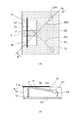
図8は、参考例としての記録材検知装置40を示す図であり、(a)は記録材検知装置の上視図、(b)は(a)のA−A断面図である。なお、(a)では、光源等の位置を分かり易くするために上部を一部透視した図として示す)。記録材検知装置40は、筐体44内の基板45に設置された砲弾型LED41を光源として、光路46を介して図中矢印方向に移動する記録材Pに向けてカバー部材Cを透過させながら10°〜15°程度の浅い角度で照明され、その反射光が集光素子(ロッドレンズ)42で集光され基板45に設置された撮像素子(ラインセンサ)43にて記録材Pの表面性状が撮像される。光源41R、41Lから出射し記録材Pに照射される光束の中心の光線(光路)46が記録材Pに投影した時に交差するように配置されている。そして、光源41Rに照射された記録材Pを撮像した画像と光源41Lに照射された記録材を撮像した画像に基づいて記録材の表面状態を検知する。
8A and 8B are diagrams showing a recording
このように構成することで、記録材を形成する繊維配向方向の影響を受けにくく、判別精度を向上させることが可能である。 With this configuration, it is difficult to be influenced by the fiber orientation direction forming the recording material, and the discrimination accuracy can be improved.
ここで、より判別精度を向上させる為、より高コントラストな画像を撮像する必要がある。この為には、光源41の発光量の増加することが考えられるが、発光量の大きい光源は光源素子の体積が大きくなり装置を大型化してしまう。また、発熱量も大きいので、筐体44や基板45等を熱膨張させてしまい、検知精度を悪化させる虞もある。そこで、カバー部材Cを無くし、カバー部材Cを透過する時にカバー部材Cの表面で反射する光を無くすことで記録材を照射する光量を増加させることが考えられる。図9にこのような参考例としての記録材検知装置の断面図を示す。
Here, in order to improve the discrimination accuracy, it is necessary to capture a higher contrast image. For this purpose, it is conceivable that the light emission amount of the
このように、カバー部材Cを無くすと、記録材検知装置40の記録材Pと当接する面に凹部が形成され、記録材PをX方向に搬送する際に記録材の先端がこの凹部に引っ掛かり、ジャムが発生しやすくなる可能性が高くなる。
Thus, when the cover member C is eliminated, a concave portion is formed on the surface of the recording
上記の課題を鑑みて、本発明の目的は、記録材の良好な搬送性を確保しつつ、判別精度を向上した記録材判別手段を備えた画像形成装置を提供することである。 In view of the above problems, an object of the present invention is to provide an image forming apparatus provided with a recording material discrimination unit that improves the discrimination accuracy while ensuring good transportability of the recording material.
記録材表面の第1照射領域及び第2照射領域を照射する為の光を発する光源と、記録材表面を撮像する撮像手段と、を備え、前記第1照射領域を照射する光束の中心光線と前記第2照射領域を照射する光束の中心光線を記録材表面に投影すると交差する関係である記録材検知手段を有し、前記撮像手段が前記第1照射領域及び前記第2照射領域を撮像した画像に基づいて記録材の表面状態に関する情報を検出する画像形成装置であって、
記録材表面と前記光源との間に設けられ、前記第1照射領域を照射する光束が通過する第1開口部と、記録材表面と前記光源との間に設けられ、前記第2照射領域を照射する光束が通過する第2開口部と、を有し、前記記録材表面に当接し、搬送される記録材を支持する当接面が前記第1開口部と前記第2開口部との間に形成されていることを特徴とする。
A light source that emits light for irradiating the first irradiation region and the second irradiation region on the surface of the recording material, and an imaging unit that images the surface of the recording material, and a central ray of a light beam that irradiates the first irradiation region; A recording material detection unit that intersects when the central ray of the light beam that irradiates the second irradiation region is projected onto the surface of the recording material, and the imaging unit images the first irradiation region and the second irradiation region; An image forming apparatus that detects information on a surface state of a recording material based on an image,
Provided between the recording material surface and the light source, provided between the recording material surface and the light source, a first opening through which a light beam that irradiates the first irradiation region passes, and the second irradiation region A second opening through which the irradiated light flux passes, and a contact surface that contacts the surface of the recording material and supports the recording material to be conveyed is between the first opening and the second opening. It is characterized by being formed.
本発明によれば、記録材の良好な搬送性を確保しつつ、判別精度を向上した記録材判別手段を備えた画像形成装置を提供することができる。 According to the present invention, it is possible to provide an image forming apparatus including a recording material determination unit that improves the determination accuracy while ensuring good conveyance of the recording material.
<第1実施形態>
本実施形態の記録材検知装置は、電子写真方式のカラー画像形成装置に搭載されている。
<First Embodiment>
The recording material detection apparatus of this embodiment is mounted on an electrophotographic color image forming apparatus.
(画像形成装置)
図1は本実施形態の記録材検知装置が搭載された画像形成装置100の概略断面図である。まず、画像形成装置100の画像形成部の構成及び動作を説明する。画像形成部は、給紙部15、CMYBk各色のステーション毎の感光体(以下感光ドラムという)1(1Y、1M、1C、1Bk)、一次帯電手段としての帯電ローラ2(2Y、2M、2C、2Bk)、露光スキャナ部11(11Y、11M、11C、11Bk)、現像手段としての現像器8(8Y、8M、8C、8Bk)、中間転写ベルト24、中間転写ベルトを駆動する駆動ローラ23、および張架ローラ13、二次転写対向ローラ26、一次転写ローラ4(4Y、4M、4C、4Bk)、二次転写ローラ25、二次転写対向ローラ26、および定着部21、およびこれらを制御動作させる制御部10によって構成されている。
(Image forming device)
FIG. 1 is a schematic cross-sectional view of an
制御部10が画像形成信号を受け取ると、記録材Pは、給紙カセット15から給紙ローラ17、18によって画像形成装置内に送り出され、レジストローラ対19a、19bに一旦挟持され、停止して待機する。
When the
一方、制御部10は、感光ドラム1を不図示の駆動源によって図中時計周り方向に回転させる。回転している感光ドラム1は、帯電ローラ2によって帯電され、露光スキャナ部11により受け取った画像信号に応じて露光されることで、表面に静電潜像が形成される。
On the other hand, the
ここで現像器8(8Y、8M、8C、8Bk)は感光ドラム1の静電潜像を可視化する手段であり、ステーション毎にイエロー(Y)、マゼンダ(M)、シアン(C)、ブラック(Bk)の現像を行う。現像器8には、それぞれスリーブ5(5Y、5M、5C、5Bk)が設けられており、静電潜像を可視化するための現像バイアスが印加される。
Here, the developing devices 8 (8Y, 8M, 8C, 8Bk) are means for visualizing the electrostatic latent image on the
感光ドラム1の表面に形成された静電潜像は、現像器8の作用により単色トナー像として現像される。
The electrostatic latent image formed on the surface of the
中間転写ベルト24は、各感光ドラム1Y、1M、1C、1Bkに接触しており、カラー画像形成時に反時計周り方向に感光ドラム1の回転と同期して回転する。感光ドラム1(1Y、1M、1C、1Bk)の表面で現像された単色トナー像は一次転写ローラ4に印加された一次転写バイアスの作用により中間転写ベルト24上に順次重ねて転写され、多色トナー像となる。中間転写ベルト24上の多色トナー像は、中間転写ベルトと二次転写ローラ25とで形成される二次転写ニップ部に搬送される。これと同時に、搬送ローラ対19abに挟持された状態で待機していた記録材Pがレジストローラ対19a、19bにより中間転写ベルト上の多色トナー像と同期を取りながら二次転写ニップ部に搬送される。そして、中間転写ベルト24上の多色トナー像が二次転写ローラ25に印加された二次転写バイアスの作用により記録材P上に一括転写される。
The
定着部21は、記録材Pを搬送させながら、転写された多色トナー像を溶融定着させるものであり、図1に示すように記録材Pを加熱する定着ローラ21aと記録材Pを定着ローラ21aに圧接させるための加圧ローラ21bを備えている。定着ローラ21aと加圧ローラ21bは中空状に形成され、内部にそれぞれヒータ21ah、21bhが内蔵されている。多色トナー像が転写された記録材Pは定着ローラ21aと加圧ローラ21bにより搬送されるとともに、熱及び圧力を加えられ、多色トナー像が記録材Pに定着される。その後、記録材Pは、排出ローラ20によって排紙トレイ16に排出され画像形成動作を終了する。クリーニング手段28は、中間転写ベルト24上に転写残として残ったトナーをクリーニングするものであり、ここで回収された転写残トナーは廃トナーとしてクリーナ容器29に蓄えられる。
The fixing
このような一連の画像形成動作は画像形成装置内に設けられた制御部10によって制御される。
Such a series of image forming operations is controlled by the
図1の画像形成装置において、本発明の記録材検知装置50はレジストローラ対19a、19bの手前の記録材判別部に設置されていて、給紙カセット15等から搬送された記録材Pの表面平滑性を反映した情報を検出する。本実施形態において記録材検知装置50による記録材の判別は、記録材Pが給紙カセット15等から画像形成装置内に送り出され、レジストローラ対19a、19bに挟持されて停止している間に行われる。そして、記録材検知装置50が出力した判別情報をもとに、制御部10が最適な転写バイアスや定着温度等の画像形成条件を設定して画像形成装置を制御動作させる。
In the image forming apparatus of FIG. 1, the recording
(記録材検知装置)
次に、記録材検知装置について説明する。図3(a)は、記録材検知装置50の上視図である。光源等の配置を分かり易くするために筐体54の一部を透視させた状態で示す。(b)は(a)のB−B断面図である。記録材検知装置50は、筐体54内には二つの光源51R、Lとしての砲弾型LED、集光部材52としての結像レンズアレイ、撮像手段53としてのCMOSラインセンサが設けられている。2つの光源51R、Lと撮像手段53は、筐体54内の基板55に設置されている。光軸56R、Lは光源51R、Lから発せられる光束の中心光線である。光源51R、Lから光束は光軸が記録材Pに対して10°〜15°傾斜した浅い角度で入射する。記録材Pの表面で反射した光は集光部材52で集光され撮像手段53に入射する。このようにして光が照射された状態の記録材P表面の陰影を撮像することができる。この時、記録材P表面の光源51Lから出射した光束が照射される領域を第1光照射領域、光源51Rから出射した光束が照射される領域を第2光照射領域とする。図3(b)の矢印は記録材Pの搬送方向Tを示す。撮像手段53は搬送方向Tに直交する方向に複数画素が配列されたラインセンサであり、順次搬送しながら記録材P表面を1ライン(記録材P表面の一方向に配列された複数画素が一度に撮像する領域)ごとに撮像を行っていく。このようにして記録材P表面を複数ライン撮像することで、1ラインの長さに対応する横幅と記録材を搬送した長さに対応する縦幅を有する記録材P表面の画像を得ることができる。
(Recording material detector)
Next, the recording material detection apparatus will be described. FIG. 3A is a top view of the recording
より具体的に説明する。図2は記録材検知装置の光路構成の上視図。光源51R、51Lから光路56R、56Lによって照射された記録材Pの撮像位置を図2に示す。光源から51R、51Lから発せられた光束は所定の拡がり角度をもって記録材P上の第1光照射領域Prj−R、第2光照射領域Prj−Lを照射する。撮像手段53が撮像するのは、この光が照射された記録材P上の第1、2光照射領域のうちの撮像手段53に対応する領域である。つまり、記録材P上の領域のうちの撮像手段53に対応する領域とは、第1、2光照射領域Prj−R、Prj−Lのうち、反射した光が撮像手段53の幅WPrj−Rと幅WPrj−Lの部分に入射する領域である。この撮像手段53により幅WPrj−Rの画像と幅WPrj−Lの画像を得ることができる。この撮像手段53の幅WPrj−Rで撮像した画像と幅WPrj−Lで撮像した2つの画像は、記録材P表面の凹凸による陰影を示す画像であり、記録材Pの表面性状(表面状態)を示す画像である。この画像をもとに記録紙の種類を判別する。
This will be described more specifically. FIG. 2 is a top view of the optical path configuration of the recording material detection apparatus. The imaging positions of the recording material P irradiated from the
本実施形態では、記録材Pの表面に投影した時に光軸56Rと光軸56Lとが交差する関係となっており、撮像手段53の幅WPrj−Rで撮像した画像と幅WPrj−Lで撮像した画像は、異なる角度で光が照射された記録材P表面を画像となる。このように異なる角度で光が照射された2つの記録材P表面の画像を用いて記録材の表面性を判断することで、記録紙Pの繊維の方向と光を照射した方向との関係に起因する検出結果のばらつきを軽減することができる。
In the present embodiment, the
ここで、本実施形態では、記録材検知装置50には、図8の参考例に示したカバー部材Cのような透過部材は設けられておらず、光源51R、Lから記録材Pへ光を直接照射する。このため、カバー部材を設けた場合と比べて、カバー部材を透過する際にカバー部材の表面で反射する光が無くなるので、記録材を照射する光量を増加させ、高コントラストな画像を撮像し記録材の判別精度を向上することができる。
Here, in the present embodiment, the recording
しかしながら、カバー部材を無くしたことにより、前述したように、記録材検知装置50の記録材Pと当接する面に凹部が形成されため、記録材Pを搬送する際に記録材の先端がこの凹部に引っ掛かってジャムが発生する虞がある。
However, since the cover member is eliminated, a concave portion is formed on the surface of the recording
そこで本実施形態では、記録材Pの判別に影響の無い箇所で記録材Pと当接し、凹部で引っかからないよう搬送される記録材を支持する当接面Sを形成している。この当接面Sに記録材Pが当接することで記録材Pと撮像手段53との距離が決まる。 Therefore, in the present embodiment, the contact surface S that contacts the recording material P at a position that does not affect the determination of the recording material P and supports the recording material that is conveyed so as not to be caught by the concave portion is formed. The distance between the recording material P and the imaging means 53 is determined by the recording material P contacting the contact surface S.
図2において示すように、撮像手段53の幅WPrj−Dの中央部は撮像機能を有している。しかし、記録材Pのこの中央部に対応する領域は光源51R、L双方からの光が照射されるため、撮像しても記録材Pの表面性状はうまく表れない。このため、撮像手段53の中央部では記録材Pを撮像しておらず、撮像手段53は撮像に必要な部分(WPrj−R、WPrj−L)だけを設け、1ラインを2つのラインセンサで構成しても良い。しかし、撮像素子自身の位置決め精度、撮像素子間の位置精度等を含めた取扱いからいうと1部品で構成した方が作業性、位置決め精度容易に保証することができるため、本実施形態では中央部を有する1つのラインセンサを用いている。
As shown in FIG. 2, the central part of the width WPrj-D of the image pickup means 53 has an image pickup function. However, since the area corresponding to this central portion of the recording material P is irradiated with light from both the
本実施形態では、記録材Pの判別に影響の無い箇所である、撮像手段53の中央部である幅WPrj−Dの部分に対応する部分にリブRを設け、このリブRに上述した記録材Pに当接し、記録材を支持する当接面Sを設けている。つまり、筐体54には、撮像手段53の幅WPrj−Rに対応する部分には、光源51Lからの光束が通過して記録材Pを照射し、反射した光束が通過し撮像手段53の幅WPrj−Rに入射する第1開口部Arがある。また、同様に、筐体54には、撮像手段53の幅WPrj−Lに対応する部分には、光源51Rからの光束が通過して記録材Pを照射し、反射した光束が通過し撮像手段53の幅WPrj−Lに入射する第2開口部Alがある。そして、当接面Sは、第1開口部Arと第2開口部Alとの間に記録材Pの搬送方向Tに沿って形成され、搬送される記録材Pがこの当接面Sに支持されガイドされる。このため、ジャムを発生しにくく、記録材Pは安定して搬送される。
In the present embodiment, a rib R is provided at a portion corresponding to the width WPrj-D, which is the central portion of the image pickup means 53, which is a portion that does not affect the determination of the recording material P, and the above-described recording material is provided on the rib R. An abutting surface S that abuts on P and supports the recording material is provided. That is, in the
以上説明したように、本実施形態では、2つの方向から記録紙に光をカバーガラス等を透過させることなく記録材Pの表面に直接照射することにより記録材Pの表面を照射する光の光量を十分確保し、高精度に記録材Pを判別することができる。更に、2つの開口部の間に当接面Sを設けることで記録材Pを安定して搬送することを可能としている。 As described above, in the present embodiment, the amount of light that irradiates the surface of the recording material P by directly irradiating the surface of the recording material P from two directions without passing through the cover glass or the like. The recording material P can be discriminated with high accuracy. Further, the recording material P can be stably conveyed by providing the contact surface S between the two openings.
<第2実施形態>
次に、本発明の第2実施形態について説明する。図4(b)は記録材検知装置60の上視図である。光源等の配置を分かり易くする為に筐体64の一部を透視させた状態で示す。(a)は(b)における記録材検知装置60のB−B断面。(c)は記録材検知装置60の側面図であり、搬送方向T下流側から見た断面図である。記録材検知装置60は、筐体64内の基板65上に設置されたチップ実装型LED61R、Lを光源として、光路66R、Lを介して記録材Pに向けて照明される。この時記録材照射方向は偏向器(反射鏡)67R、Lによって装置内で光路を偏向され、記録材Pへと誘導される。記録材Pの表面に照射された光は反射して集光部材62で集光され、基板65に設置された撮像手段63にて記録材表面性状が撮像される。このように、光源から撮像手段までの光路において、第1実施形態と異なるのは、光源61R、Lと、偏向器67R、Lを介した光路となっていることであり、撮像手段63は第1実施形態と同様である。そして、記録材検知装置60は、第1実施形態の記録材検知装置50と同様のしくみで記録材Pの判別を行う。即ち、記録紙表面性状が記録紙繊維配向方向に拠らず判別できるように光源61R、61Lから偏向器67R、67Lを介して光路66R、66Lのように2方向から記録紙Pに向けて照射されている。なお、偏向器67はガラスやアクリルのような板材表面に、反射膜等を形成したり、例えば東レ社のPET基材にアルミ蒸着を施したメタルミー(商標)等の反射率が高いシート材を両面テープ等で接着したりして形成してもよい。また、筐体64の一部に直接反射面を蒸着等で形成してもよい。また、記録材検知装置60においても、第1実施形態と同様に第1開口部Arと第2開口部Alの間にリブRを設け当接面Sを形成されている。
Second Embodiment
Next, a second embodiment of the present invention will be described. FIG. 4B is a top view of the recording
本実施形態では、光学的な検知ノイズを減少させる為に、第1開口部Ar及び第2開口部Alの内周面(リブRの側面及び筐体64のリブRに対向する面)にテーパ面を形成している。このテーパ面について詳しく説明する。図5(a)は、テーパ面の無い記録材検知装置の上視図(光源等の配置を分かり易くする為に筐体64の一部を透視させた状態で示す。)である。(c)は(a)の記録材検知装置の側面図である。(b)は、本実施形態の記録材検知装置60の上視図(光源等の配置を分かり易くする為に筐体64の一部を透視させた状態で示す。)である。(d)は、本実施形態の記録材検知装置60の側面図である。
In the present embodiment, in order to reduce optical detection noise, the inner peripheral surfaces of the first opening Ar and the second opening Al (side surfaces of the rib R and the surface facing the rib R of the housing 64) are tapered. A surface is formed. This tapered surface will be described in detail. FIG. 5A is a top view of the recording material detection apparatus having no taper surface (shown in a state where a part of the casing 64 is seen through in order to make the arrangement of the light source and the like easier to understand). (C) is a side view of the recording material detection apparatus of (a). (B) is a top view of the recording
それぞれ、偏向器以降の光源61R、Lからの光束の光軸(光線中心)を66R、66Lで示す。光源61R、Lからの光束のうち光軸に対して拡がって出射された光線を66R−a、66R−b、66L−a、66L−bで示す。例えば、光源61Lから、光軸66Lに対して右側に拡がって出射された光線66L−aは、第1開口部の内周面の搬送方向に沿う外側の面(外側面)S−r面で反射し、集光レンズ62、撮像手段63に入射し光学的なノイズ成分となってしまう。また、光軸66Lに対して左側に拡がって出射された光線66L−bは第2開口部の内周面の搬送方向に沿う内側の面(リブRの左側面)R−l面で反射し、同様に集光レンズ62、撮像手段63に入射し、光学的なノイズ成分となる。光源61Rから出射した光も同様に光学的なノイズ成分となる虞がある。
The optical axes (light ray centers) of the light beams from the
そこで本実施形態では、図5(b)、(d)に示すよう、第1開口部Ar、第2開口部Alの内周面である、面S−r、l、面R−r、lにテーパ面を付ける。このテーパ面は、記録材P表面に直交する方向に対して傾斜しており、記録材P表面に直交する方向で撮像手段63に向かうにつれて第1開口部Ar、第2開口部Alの幅が広がるように傾斜している。このため、光源から拡がって出射された光線66L−a、b、66R−a、bはそれぞれ下方に反射される。このように第1開口部Ar、第2開口部Alの内周面で下方に反射された光線66L−a、b、66R−a、bは、撮像手段63の撮像領域である幅WPrj−R、WPrj−Lの部分には入射しない。このため、撮像手段に本来の記録材P表面からの反射光以外の光が入射して光学的ノイズとなることを低減することができる。 Therefore, in the present embodiment, as shown in FIGS. 5B and 5D, the surfaces Sr and l, and the surfaces Rr and l, which are inner peripheral surfaces of the first opening Ar and the second opening Al, are provided. A tapered surface is attached to. This taper surface is inclined with respect to the direction orthogonal to the surface of the recording material P, and the widths of the first opening Ar and the second opening Al increase in the direction orthogonal to the surface of the recording material P toward the imaging means 63. Inclined to spread. For this reason, the light beams 66L-a, b, 66R-a, b emitted from the light source are reflected downward. Thus, the light rays 66L-a, b, 66R-a, b reflected downward on the inner peripheral surfaces of the first opening Ar and the second opening Al are the width WPrj-R which is the imaging region of the imaging means 63. , WPrj-L does not enter. For this reason, it can be reduced that light other than the reflected light from the surface of the original recording material P is incident on the image pickup means and becomes optical noise.
以上説明したように、本実施形態では、第1実施形態同様に、2つの方向から記録紙に光をカバーガラス等を透過させることなく記録材Pの表面に直接照射することにより記録材Pの表面を照射する光の光量を十分確保し、高精度に記録材Pを判別することができる。また、2つの開口部の間に当接面Sを設けることで記録材Pを安定して搬送することを可能としている。 As described above, in this embodiment, as in the first embodiment, the recording material P is directly irradiated from the two directions onto the surface of the recording material P without passing through the cover glass or the like. A sufficient amount of light for irradiating the surface can be secured and the recording material P can be discriminated with high accuracy. Further, by providing the contact surface S between the two openings, the recording material P can be stably conveyed.
さらに、本実施形態では、2つの開口部の内周面にテーパ面を設け、撮像手段63の撮像領域にこのテーパ面で反射した光が入射しないようにし、光学的なノイズ成分を低減し、記録材Pの判別精度を向上させることができる。
Further, in the present embodiment, a tapered surface is provided on the inner peripheral surfaces of the two openings so that light reflected by the tapered surface does not enter the imaging region of the
<第3実施形態>
次に、本発明の第3実施形態について説明する。図6は、記録材検知装置70の筐体上面を示す図ある。第2実施形態と同様のものについては同じ符号を付して説明を省略する。第1開口部Ar、第2開口部Alの記録材Pの搬送方向Tに直交する方向の幅が、搬送方向Tの上流から下流に向かうにつれて広くなるようになっている。つまり、リブRの搬送方向Tに直交する方向の幅が搬送方向Tの上流から下流に向かってLbからLu(Lu<Lb)となるようにリブRの側面部を搬送方向Tに対して傾斜させて構成している。このように不均一にすることにより、先述の光源61R、Lからの光が撮像手段63の撮像領域に入射することを防止できる。なお、本実施形態ではLu<Lbであるが、Lu≠Lbのように、第1開口部Ar、第2開口部Alの記録材Pの搬送方向Tに直交する方向の幅が、搬送方向Tに向かって不均一となっていれば良い。
<Third Embodiment>
Next, a third embodiment of the present invention will be described. FIG. 6 is a view showing the upper surface of the housing of the recording
また、第1、第2開口部Ar、Alの内周面のリブRに対向する面も図示したようなギャップLSを設けるよう搬送方向Tに対して傾斜させることにより、同様に光源61R、Lからの光が撮像手段63の撮像領域に入射することを防止できる。
Similarly, the surfaces of the first and second openings Ar, Al facing the ribs R on the inner peripheral surface are inclined with respect to the transport direction T so as to provide the gap LS as shown in the figure, thereby similarly providing the
次に本実施形態の他の形態について説明する。図7は、記録材検知装置70の筐体上面を示す図である。なお、集光レンズ62、撮像手段63は図6と同様の配置のため記載を省略している。第1開口部Ar、第2開口部Alの内周面のうち搬送方向Tに沿う方向の面の形状を長さLt傾きθのノコギリ形状にしている。これにより、同様に光源61R、Lからの光が撮像手段63の撮像領域に入射することを防止できる。
Next, another embodiment of the present embodiment will be described. FIG. 7 is a view showing the upper surface of the housing of the recording
以上説明したように、本実施形態では、第1実施形態同様に、2つの方向から記録紙に光をカバーガラス等を透過させることなく記録材Pの表面に直接照射することにより記録材Pの表面を照射する光の光量を十分確保し、高精度に記録材Pを判別することができる。また、2つの開口部の間に当接面Sを設けることで記録材Pを安定して搬送することを可能としている。 As described above, in this embodiment, as in the first embodiment, the recording material P is directly irradiated from the two directions onto the surface of the recording material P without passing through the cover glass or the like. A sufficient amount of light for irradiating the surface can be secured and the recording material P can be discriminated with high accuracy. Further, by providing the contact surface S between the two openings, the recording material P can be stably conveyed.
さらに、本実施形態では、2つの開口部の記録材Pの搬送方向Tに直交する方向の幅が、搬送方向Tに向かって不均一となるように、搬送方向Tに対して傾斜させて構成している。このため、この2つの開口部の内周面で反射した光が、撮像手段63の撮像領域に入射しないようにし、光学的なノイズ成分を低減し、記録材Pの判別精度を向上させることができる。 Further, in the present embodiment, the width of the two openings in the direction perpendicular to the conveyance direction T of the recording material P is inclined with respect to the conveyance direction T so as to be non-uniform toward the conveyance direction T. is doing. For this reason, it is possible to prevent the light reflected by the inner peripheral surfaces of the two openings from entering the imaging region of the imaging means 63, reduce the optical noise component, and improve the discrimination accuracy of the recording material P. it can.
なお、本実施形態の開口部の内周面の形状は第2実施形態と組合せて構成しても良い。 In addition, you may comprise the shape of the internal peripheral surface of the opening part of this embodiment combining with 2nd Embodiment.
50 記録材検知装置
51R、L 光源
52 集光部材
53 撮像手段
54 筐体
55 基板
56R、L 光路
60 記録材検知装置
61R、L 光源
62 集光部材(集光レンズ)
63 撮像手段
64 筐体
65 基板
66R、L 光路
67R、L 反射鏡
Ar 第1開口部
Al 第2開口部
R リブ
S 当接面
R−r、R−l、S−r、S−l 内周面
T 記録材搬送方向
DESCRIPTION OF
63 Imaging means 64
Claims (5)
前記撮像手段が前記第1照射領域及び前記第2照射領域を撮像した画像に基づいて記録材の表面状態に関する情報を検出する画像形成装置であって、
記録材表面と前記光源との間に設けられ、前記第1照射領域を照射する光束が通過する第1開口部と、記録材表面と前記光源との間に設けられ、前記第2照射領域を照射する光束が通過する第2開口部と、を有し、
前記記録材表面に当接し、搬送される記録材を支持する当接面が前記第1開口部と前記第2開口部との間に形成されていることを特徴とする画像形成装置。 A light source that emits light for irradiating the first irradiation region and the second irradiation region on the surface of the recording material, and an imaging unit that images the surface of the recording material, and a central ray of a light beam that irradiates the first irradiation region; A recording material detecting means that intersects the central beam of the light beam that irradiates the second irradiation region when projected onto the surface of the recording material;
An image forming apparatus for detecting information on a surface state of a recording material based on an image obtained by imaging the first irradiation area and the second irradiation area by the imaging unit,
Provided between the recording material surface and the light source, provided between the recording material surface and the light source, a first opening through which a light beam that irradiates the first irradiation region passes, and the second irradiation region A second opening through which the irradiated light flux passes,
An image forming apparatus, wherein an abutting surface that abuts the recording material surface and supports the conveyed recording material is formed between the first opening and the second opening.
Priority Applications (1)
| Application Number | Priority Date | Filing Date | Title |
|---|---|---|---|
| JP2010275136A JP2012123273A (en) | 2010-12-09 | 2010-12-09 | Image forming apparatus |
Applications Claiming Priority (1)
| Application Number | Priority Date | Filing Date | Title |
|---|---|---|---|
| JP2010275136A JP2012123273A (en) | 2010-12-09 | 2010-12-09 | Image forming apparatus |
Publications (1)
| Publication Number | Publication Date |
|---|---|
| JP2012123273A true JP2012123273A (en) | 2012-06-28 |
Family
ID=46504757
Family Applications (1)
| Application Number | Title | Priority Date | Filing Date |
|---|---|---|---|
| JP2010275136A Pending JP2012123273A (en) | 2010-12-09 | 2010-12-09 | Image forming apparatus |
Country Status (1)
| Country | Link |
|---|---|
| JP (1) | JP2012123273A (en) |
Cited By (4)
| Publication number | Priority date | Publication date | Assignee | Title |
|---|---|---|---|---|
| JP2014032090A (en) * | 2012-08-02 | 2014-02-20 | Canon Inc | Apparatus for detecting recording material and image forming device |
| JP2014114131A (en) * | 2012-12-11 | 2014-06-26 | Canon Inc | Recording material discrimination device and image formation apparatus including the same |
| JP2017128449A (en) * | 2017-03-01 | 2017-07-27 | キヤノン株式会社 | Recording material determination device and image forming apparatus including the same |
| JP2018200478A (en) * | 2018-07-25 | 2018-12-20 | キヤノン株式会社 | Recording material determination device and image forming apparatus including the same |
-
2010
- 2010-12-09 JP JP2010275136A patent/JP2012123273A/en active Pending
Cited By (5)
| Publication number | Priority date | Publication date | Assignee | Title |
|---|---|---|---|---|
| JP2014032090A (en) * | 2012-08-02 | 2014-02-20 | Canon Inc | Apparatus for detecting recording material and image forming device |
| US9389563B2 (en) | 2012-08-02 | 2016-07-12 | Canon Kabushiki Kaisha | Recording material detecting apparatus and an image-forming apparatus |
| JP2014114131A (en) * | 2012-12-11 | 2014-06-26 | Canon Inc | Recording material discrimination device and image formation apparatus including the same |
| JP2017128449A (en) * | 2017-03-01 | 2017-07-27 | キヤノン株式会社 | Recording material determination device and image forming apparatus including the same |
| JP2018200478A (en) * | 2018-07-25 | 2018-12-20 | キヤノン株式会社 | Recording material determination device and image forming apparatus including the same |
Similar Documents
| Publication | Publication Date | Title |
|---|---|---|
| JP5456098B2 (en) | Image forming apparatus | |
| US9389563B2 (en) | Recording material detecting apparatus and an image-forming apparatus | |
| JP6103912B2 (en) | Recording material discrimination device and image forming device equipped with it | |
| JP2012123273A (en) | Image forming apparatus | |
| JP5546152B2 (en) | Recording material surface detection apparatus and image forming apparatus including the same | |
| JP5274350B2 (en) | Recording material surface detection apparatus and image forming apparatus including the same | |
| JP2010249614A (en) | Recording material surface detecting device, and image forming apparatus having the same | |
| US10073372B1 (en) | Optical scanner and image forming apparatus | |
| JP2009271273A (en) | Recording material surface image pickup device and image forming apparatus equipped with the same | |
| JP5559392B2 (en) | Recording material detection apparatus and image forming apparatus including the same | |
| JP2010117417A (en) | Recording material discriminating device and image forming apparatus using the same | |
| JP2013210240A (en) | Recording material discrimination device and image forming apparatus | |
| JP2013080176A (en) | Recording material discriminating device, and image forming apparatus | |
| JP5783753B2 (en) | Recording material discrimination device | |
| JP2020027036A (en) | Water content sensor | |
| JP2019045373A (en) | Sensor for determining recording material and image forming apparatus | |
| JP6643413B2 (en) | Recording material discriminating apparatus and image forming apparatus having the same | |
| JP6377195B2 (en) | Recording material discriminating apparatus and image forming apparatus having the same | |
| JP2022017377A (en) | Water detector and image forming device | |
| JP6269087B2 (en) | Optical sensor and image forming apparatus | |
| JP2011242519A (en) | Image information detecting device and image forming apparatus having the same | |
| JP2016040638A (en) | Recording material discrimination device and image forming apparatus | |
| JP2017171423A (en) | Image formation device and control method thereof | |
| JP2007333967A (en) | Optical write-in apparatus, image forming apparatus and method of image forming |