JP2012122485A - Blisk - Google Patents
Blisk Download PDFInfo
- Publication number
- JP2012122485A JP2012122485A JP2012068356A JP2012068356A JP2012122485A JP 2012122485 A JP2012122485 A JP 2012122485A JP 2012068356 A JP2012068356 A JP 2012068356A JP 2012068356 A JP2012068356 A JP 2012068356A JP 2012122485 A JP2012122485 A JP 2012122485A
- Authority
- JP
- Japan
- Prior art keywords
- blisk
- rotor
- circumferential groove
- friction
- rotation shaft
- Prior art date
- Legal status (The legal status is an assumption and is not a legal conclusion. Google has not performed a legal analysis and makes no representation as to the accuracy of the status listed.)
- Pending
Links
Images


Abstract
Description
本発明は、タービンや圧縮機等の軸流式空気機械に用いられ、ロータを構成する翼とロータディスクが一体に成形されたブリスクに関する。 The present invention relates to a blisk in which a blade and a rotor disk forming a rotor are integrally formed and used in an axial-flow type air machine such as a turbine or a compressor.
航空機用ジェットエンジンや、ガスタービン、蒸気タービン等には、通常、タービンや圧縮機などの軸流式空気機械を有している。このような軸流式空気機械には、通常、翼(動翼)が外周に配列された回転体であるロータを有している。 An aircraft jet engine, a gas turbine, a steam turbine, and the like usually have an axial air machine such as a turbine or a compressor. Such an axial flow type air machine usually has a rotor which is a rotating body having blades (moving blades) arranged on the outer periphery.
このようなロータを構成するために、円板状の部材である複数のロータディスクと、各ロータディスクの外周に配列される翼に、ロータを分割した構造として、各ロータディスクの外周に翼を配列し結合した結合体を構成し、複数の結合体をロータ回転軸の軸方向に列をなして重ねて結合する技術が知られている(例えば、特許文献1,2参照)。 In order to configure such a rotor, the rotor is divided into a plurality of rotor disks, which are disk-shaped members, and the blades arranged on the outer periphery of each rotor disk. A technique is known in which a combined body is arranged and connected, and a plurality of combined bodies are connected in a row in the axial direction of the rotor rotation shaft (see, for example, Patent Documents 1 and 2).
下記の特許文献1,2には、それぞれ別体としてタービンの動翼と、ロータディスク(ディスク)を成形し、ロータディスクの外周に形成された翼溝に、動翼の植込み部(翼根)を嵌め込むことで、ロータディスクと翼とを結合する技術が記載されている。 In the following Patent Documents 1 and 2, a turbine rotor blade and a rotor disk (disk) are formed as separate bodies, respectively, and a blade implantation part (blade root) is formed in a blade groove formed on the outer periphery of the rotor disk. A technique is described in which the rotor disk and the blades are coupled by fitting the rotor disk.
また、従来から、削り出しや精密鋳造により、ロータディスクと翼が一体に成形された結合体であるブリスク(Blade in disk:Blisk)を構成し、これをロータ回転軸の軸方向に列をなして重ねて結合することで、軸流式空気機械のロータを構成する技術が知られている。 Also, conventionally, a blade in blade (Blisk), which is a combined body in which the rotor disk and blades are integrally molded, is formed by machining and precision casting, and this is arranged in the axial direction of the rotor rotation axis. There is known a technique for constructing a rotor of an axial-flow type pneumatic machine by overlapping and joining together.
上述のような軸流式空気機械において、翼の振動を抑制するため、特許文献1には、隣り合う翼の翼根(プラットホーム)の間に、弾性を有する振動減衰材を配設することで、翼に生じる振動を減衰させる技術が提案されている。また、特許文献2には、ロータディスクの溝と、翼の植込み部との間に弾性体を配設することで、翼の振動を減衰させる技術が提案されている。 In the axial flow type air machine as described above, in order to suppress blade vibration, Patent Document 1 discloses that an elastic vibration damping material is disposed between the blade roots (platforms) of adjacent blades. A technique for attenuating vibration generated in a blade has been proposed. Patent Document 2 proposes a technique for attenuating vibrations of a blade by disposing an elastic body between a rotor disk groove and a blade implantation portion.
しかし、特許文献1,2に記載の技術では、ロータディスクと翼とを別々に製作し、結合する必要があるため、ロータディスクと翼とを一体に成形するブリスクを構成してロータを製作する場合に比べて必要なコストが高くなるという問題がある。 However, in the techniques described in Patent Documents 1 and 2, since it is necessary to separately manufacture and combine the rotor disk and the blade, the rotor is manufactured by forming a blisk that integrally molds the rotor disk and the blade. There is a problem that the necessary cost is higher than in the case.
一方、上述のブリスクでロータを構成する場合、特許文献1,2のように翼根と翼溝との間に生じる摩擦を利用して、翼の振動を減衰することができない。ブリスクの隣り合う翼同士をルースワイヤ等により接続することで翼の振動を減衰する技術も提案されているが、この技術を採用すると、翼にルースワイヤ等を装着するための構造や加工が必要となるため好ましくない。したがって、ブリスクにより軸流式空気機械のロータを構成する場合、翼に新たな構造を付加することなく、軸流式空気機械の運転中に、翼に生じる振動を減衰する技術が要望されている。 On the other hand, when the rotor is configured with the above blisk, the vibration of the blade cannot be damped by utilizing the friction generated between the blade root and the blade groove as in Patent Documents 1 and 2. A technology to attenuate blade vibration by connecting adjacent blades of blisk with loose wires has also been proposed. However, if this technology is used, a structure and processing for attaching loose wires to the blades are required. This is not preferable. Therefore, when a rotor of an axial-flow type air machine is configured by blisk, there is a demand for a technique for attenuating vibration generated in the blade during operation of the axial-flow type air machine without adding a new structure to the blade. .
本発明は、上記に鑑みてなされたものであって、翼に生じる振動を、摩擦を利用して減衰可能な軸流式空気機械用のブリスクを提供することを目的とする。 This invention is made in view of the above, Comprising: It aims at providing the blisk for axial-flow-type air machines which can attenuate the vibration which arises in a blade | wing using friction.
上記の目的を達成するために、本発明に係るブリスクは、軸流式空気機械に用いられ、ロータを構成する翼とロータディスクが一体に成形されたブリスクであって、ロータ回転軸の周方向に延びており、ロータ回転軸の径方向内側からロータディスクに接して、当該ロータディスクとの間に摩擦を発生可能な摩擦部材、を有し、ロータディスクには、ロータ回転軸の周方向に延びて摩擦部材を挿入可能な周方向溝が形成されており、ロータディスクのうちロータ回転軸の径方向外側には、径方向内側に比べてロータ回転軸方向の幅が大きく設定されて翼が結合されるプラットホーム部を有し、周方向溝は、当該プラットホーム部に形成されており、周方向溝は、溝底がロータ回転軸の軸方向外側に面するよう構成されていることを特徴とする。 In order to achieve the above object, a blisk according to the present invention is a blisk used in an axial-flow type air machine, in which blades constituting a rotor and a rotor disk are integrally formed, and the circumferential direction of the rotor rotation shaft A friction member that is in contact with the rotor disk from the inside in the radial direction of the rotor rotation shaft and is capable of generating friction between the rotor disk and the rotor disk in the circumferential direction of the rotor rotation shaft. A circumferential groove is formed so that the friction member can be inserted into the rotor disk, and the rotor disk has a larger width in the rotor rotation axis direction than the radially inner side of the rotor rotation axis. It has a platform portion to be coupled, and the circumferential groove is formed in the platform portion, and the circumferential groove is configured such that the groove bottom faces the outer side in the axial direction of the rotor rotation shaft. Do
本発明に係るブリスクにおいて、摩擦部材は、平板状をなしており、ロータ回転軸の径方向外側の側壁に接するよう周方向溝に挿入されているものとすることができる。 In the blisk according to the present invention, the friction member has a flat plate shape and can be inserted into the circumferential groove so as to be in contact with the radially outer side wall of the rotor rotation shaft.
本発明に係るブリスクにおいて、摩擦部材のうち周方向溝と接する面は、弾性材で構成されているものとすることができる。 In the blisk according to the present invention, the surface of the friction member that contacts the circumferential groove can be made of an elastic material.
本発明に係るブリスクにおいて、摩擦部材は、開端を有してC字状に延びている摩擦リングであるものとすることができる。 In the blisk according to the present invention, the friction member may be a friction ring having an open end and extending in a C shape.
本発明に係るブリスクによれば、ロータ回転軸の周方向に延びており、ロータ回転軸の径方向内側からロータディスクに接して、当該ロータディスクとの間に摩擦を発生可能な摩擦部材を有し、ロータディスクには、ロータ回転軸の周方向に延びて摩擦部材を挿入可能な周方向溝が形成されており、ロータディスクのうちロータ回転軸の径方向外側には、径方向内側に比べてロータ回転軸方向の幅が大きく設定されて翼が結合されるプラットホーム部を有し、周方向溝は、当該プラットホーム部に形成されており、周方向溝は、溝底がロータ回転軸の軸方向外側に面するよう構成されているものとしたので、摩擦部材の周方向溝への挿入を容易なものとすることができる。 According to the blisk of the present invention, there is a friction member that extends in the circumferential direction of the rotor rotation shaft, contacts the rotor disk from the radially inner side of the rotor rotation shaft, and can generate friction with the rotor disk. The rotor disk is formed with a circumferential groove that extends in the circumferential direction of the rotor rotation shaft and into which a friction member can be inserted. The rotor rotation axis direction has a large width and a platform portion to which the blades are coupled. The circumferential groove is formed in the platform portion, and the circumferential groove has a groove bottom at the axis of the rotor rotation axis. Since it is configured to face outward in the direction, the friction member can be easily inserted into the circumferential groove.
本発明に係るブリスクにおいて、摩擦部材は、平板状をなしており、ロータ回転軸の径方向外側の側壁に接するよう周方向溝に挿入されているものとすることで、摩擦部材の製作を容易なものとしつつ、周方向溝の径方向外側の側壁と良好に接触させることができる。 In the blisk according to the present invention, the friction member has a flat plate shape and is inserted into the circumferential groove so as to be in contact with the radially outer side wall of the rotor rotation shaft, so that the friction member can be easily manufactured. It is possible to make good contact with the radially outer side wall of the circumferential groove.
本発明に係るブリスクにおいて、摩擦部材のうち周方向溝と接する面は、弾性材で構成されているものとすることで、周方向溝と摩擦部材との間における摩擦係数、すなわち周方向溝と摩擦部材との間に生じる摩擦力を増大させることができる。 In the blisk according to the present invention, the surface in contact with the circumferential groove in the friction member is made of an elastic material, so that the coefficient of friction between the circumferential groove and the friction member, that is, the circumferential groove, The friction force generated between the friction member and the friction member can be increased.
本発明に係るブリスクにおいて、摩擦部材は、開端を有してC字状に延びている摩擦リングであるものとすることで、ロータがロータ回転軸を中心に回転して摩擦部材に遠心力が作用したときに、摩擦部材を、ロータ回転軸の径方向内側からロータディスクに良好に押し付けることができる。 In the blisk according to the present invention, the friction member is a friction ring having an open end and extending in a C shape, so that the rotor rotates around the rotor rotation axis and centrifugal force is applied to the friction member. When acting, the friction member can be favorably pressed against the rotor disk from the radially inner side of the rotor rotation shaft.
以下、この発明につき図面を参照しつつ詳細に説明する。なお、この実施の形態によりこの発明が限定されるものではない。また、下記実施の形態における構成要素には、当業者が容易に想定できるもの、あるいは実質的に同一のものが含まれる。 Hereinafter, the present invention will be described in detail with reference to the drawings. Note that the present invention is not limited to the embodiments. In addition, constituent elements in the following embodiments include those that can be easily assumed by those skilled in the art or those that are substantially the same.
(実施例1)
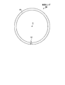
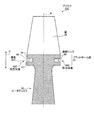
本実施例に係る軸流式空気機械用のブリスクについて図1〜図4を用いて説明する。図1は、ブリスクの全体構成を示す斜視図である。図2は、ブリスクの部分斜視図である。図3は、図1のA−A線によるブリスクの部分断面図である。図4は、ブリスクに設けられる摩擦部材の部品図である。なお、図3において、一点鎖線Bの右側には、摩擦部材が周方向溝に挿入された状態を示し、一点鎖線Bの左側には、摩擦部材が周方向溝に挿入される前の状態を示している。
Example 1
A blisk for an axial-flow air machine according to the present embodiment will be described with reference to FIGS. FIG. 1 is a perspective view showing the overall configuration of the blisk. FIG. 2 is a partial perspective view of the blisk. 3 is a partial cross-sectional view of the blisk taken along line AA in FIG. FIG. 4 is a component diagram of a friction member provided in the blisk. In FIG. 3, the right side of the alternate long and short dash line B shows a state where the friction member is inserted into the circumferential groove, and the left side of the alternate long and short dash line B shows a state before the friction member is inserted into the circumferential groove. Show.
本実施例に係るブリスク10は、航空機用エンジンの圧縮機やタービン等の軸流式空気機械のロータに用いられる。なお、軸流式空気機械には、ガスタービン及び蒸気タービンの圧縮機及びタービン等もある。
The
図1に示すように、ブリスク10は、動翼(以下、単に「翼」と記す)20と、複数の翼20が外周に配列されるロータディスク30から構成されており、複数の翼20とロータディスク30は、削り出しや鋳造等により一体に成形されている。つまり、ブリスク10は、翼20とロータディスク30が一体に成形された構造体である。ブリスク10は、図に一点鎖線Cで示すロータ回転軸の軸方向に、複数枚、列をなして重ねられ結合されて、軸流式空気機械のロータ(図示せず)を構成することとなる。
As shown in FIG. 1, the
図1及び図2に示すように、ロータディスク30のうち、ロータ回転軸の径方向(図に矢印Rで示す)の外側には、径方向内側に比べて、ロータ回転軸の軸方向の幅が大きく設定されたプラットホーム部33が、全周に亘って形成されている。プラットホーム部33のうちロータ回転軸の径方向外側には、翼20のロータ回転軸の径方向内側の端、いわゆる翼根が結合されている。
As shown in FIG. 1 and FIG. 2, in the
図3に示すように、ロータディスク30のプラットホーム部33には、ロータ回転軸の周方向に延びる溝(以下、周方向溝と記す)40が、全周に亘って形成されている。周方向溝40は、プラットホーム部33の外表面のうち、ロータ回転軸の径方向内側の面35から径方向外側に掘り下げられて形成されている。つまり、周方向溝40は、溝底44がロータ回転軸の径方向内側に面するように構成されている。周方向溝40は、溝底44と溝底44のロータ回転軸の軸方向の両側にそれぞれ形成された側壁45,46により囲まれて、後述する摩擦リング60を収容する空間が構成されている。周方向溝40は、ブリスク10において、ロータ回転軸に直交する仮想平面(図に一点鎖線Bで示す)を挟んで軸方向の両側に、面対称な形状となるよう形成されている。
As shown in FIG. 3, a groove (hereinafter referred to as a circumferential groove) 40 extending in the circumferential direction of the rotor rotation shaft is formed in the
このようにして構成された周方向溝40には、図3及び図4に示すように、ロータディスク30のプラットホーム部33に、ロータ回転軸の径方向内側から外側に向けて接して、当該プラットホーム部33との間に摩擦を発生可能な摩擦部材として、断面が略円形をなし、ロータ回転軸の周方向に延びる摩擦リング60が設けられている。摩擦リング60は、開端62を有し、C字状に延びており、金属製の棒状部材を曲げて製作することが可能である。摩擦リング60は、開端62が閉じるよう力をかけて、周方向溝40内に挿入することができる。
As shown in FIGS. 3 and 4, the
摩擦リング60は、周方向溝40内に挿入されると、その外表面66が周方向溝40の溝底44、及び側壁46,45に接する。軸流式空気機械が作動して、そのロータ及びブリスク10がロータ回転軸を中心に回転すると、摩擦リング60には、ロータ回転軸の径方向外側に向かう遠心力が作用して、外表面66が、より径方向外側にある溝底44に押し付けられる。
When the
これにより、翼20が振動し、ブリスク10が変形して、周方向溝40と摩擦リング60との間で相対的な変位が生じても、溝底44と外表面66との間には、当該変位を抑制する方向の摩擦力が生じる。この摩擦力により、翼20の振動を減衰することができ、ブリスク10に作用する振動応力を低減することができる。
As a result, even if the
本実施例に係るブリスク10は、軸流式空気機械に用いられ、ロータを構成する翼20とロータディスク30が一体に成形されたブリスク10であって、ロータ回転軸の周方向に延びており、ロータ回転軸の径方向内側からロータディスク30のプラットホーム部33に接して、当該ロータディスク30との間に摩擦を発生可能な摩擦部材として摩擦リング60を有するものとしたので、ロータがロータ回転軸を中心に回転したときに、摩擦リング60にはロータ回転軸の径方向外側に向かう遠心力が作用して、ロータディスク30のプラットホーム部33に押し付けられる。翼20が振動しブリスク10が変形して、ロータディスク30と摩擦リング60との間に相対的な変位が生じても、ロータディスク30と摩擦リング60との間には、当該変位を抑制する方向に摩擦力が生じる。この摩擦力により、翼20の振動を減衰することができる。
The
また、本実施例に係るブリスク10は、ロータディスク30には、ロータ回転軸の周方向に延びて摩擦リング60(摩擦部材)を挿入可能な周方向溝40が形成されているものとしたので、周方向溝40が摩擦リング60を収容すると共に、摩擦リング60との間で良好に接して摩擦力を生じさせることができる。
Further, in the
また、本実施例に係るブリスク10は、ロータディスク30のうちロータ回転軸の径方向外側には、径方向内側に比べてロータ回転軸方向の幅が大きく設定されて、翼20が結合されるプラットホーム部33を有し、周方向溝40は、プラットホーム部33に形成されているものとしたので、ロータがロータ回転軸を中心に回転したときに、ロータディスク30に設けられた摩擦リング60に作用する遠心力を極力高いものとすることができ、ロータディスク30との間に高い摩擦力を生じさせることができる。
Further, in the
また、本実施例に係るブリスク10は、周方向溝40は、溝底44がロータ回転軸の径方向内側に面するよう構成されているものとしたので、ロータがロータ回転軸を中心に回転したときに、周方向溝40が確実に摩擦リング60を保持して、摩擦リング60との間に摩擦力を生じさせることができる。
Further, in the
また、本実施例に係るブリスク10は、摩擦部材は、開端62を有してC字状に延びている摩擦リング60であるものとしたので、ロータがロータ回転軸を中心に回転して摩擦リング60に遠心力が作用したときに、摩擦リング60を、ロータ回転軸の径方向内側から外側に向けてロータディスク30に良好に押し付けることができる。
Further, in the
(実施例2)
本実施例に係る軸流式空気機械用のブリスクについて、図5〜図8を用いて説明する。図5は、図1のA−A線によるブリスクの部分断面図である。図6は、ブリスクに設けられる摩擦部材の部品図である。図7は、図1のA−A線による、変形例のブリスクの部分断面図である。図8は、変形例のブリスクに設けられる摩擦部材の部品図である。なお、図5及び図7において、一点鎖線Bの右側には、摩擦部材が周方向溝に挿入された状態を示し、一点鎖線Bの左側には、摩擦部材が周方向溝に挿入される前の状態を示している。
(Example 2)
A blisk for an axial flow type air machine according to the present embodiment will be described with reference to FIGS. FIG. 5 is a partial cross-sectional view of the blisk taken along line AA in FIG. FIG. 6 is a component diagram of a friction member provided in the blisk. FIG. 7 is a partial cross-sectional view of a variation blisk, taken along line AA in FIG. FIG. 8 is a component diagram of a friction member provided in a blisk of a modified example. 5 and 7, the right side of the alternate long and short dash line B shows a state in which the friction member is inserted into the circumferential groove, and the left side of the alternate long and short dash line B is before the friction member is inserted into the circumferential groove. Shows the state.
本実施例に係るブリスク10Bは、周方向溝40Bの溝底44B、及び摩擦リング70が、ロータ回転軸の径方向外側に凸となって湾曲する略円弧形状をなしている点で、実施例1と異なり、以下に詳細を説明する。なお、実施例1と略共通の構成については、同一の符号を付して説明を省略する。
The
図5に示すように、本実施例に係るブリスク10Bにおいて、ロータディスク30のプラットホーム部33には、ロータ回転軸の周方向に延びる周方向溝40Bが全周に亘って形成されている。周方向溝40Bは、プラットホーム部33のロータ回転軸の径方向内側の面35から、径方向外側に掘り下げられて形成されている。周方向溝40Bの溝底44Bは、ロータ回転軸の径方向外側に凸となって湾曲しており、ロータ回転軸の径方向内側に面するよう構成されている。溝底44Bは、径方向内側の面35に接続している。
As shown in FIG. 5, in the
このように構成された周方向溝40Bには、図5及び図6に示すように、ロータディスク30のプラットホーム部33と接して、当該プラットホーム部33との間に摩擦を発生可能な摩擦部材として、断面が略円弧状をなし、ロータ回転軸の周方向に延びている摩擦リング70が設けられている。摩擦リング70は、金属製であり、矩形の板状部材を、断面が略円弧状をなすよう湾曲させ、さらに長手方向に曲げることで製作することが可能である。摩擦リング70は、その外表面75の湾曲形状が、周方向溝40Bの溝底44Bの湾曲形状と略一致するように構成されている。
As shown in FIGS. 5 and 6, the
摩擦リング70は、周方向溝40B内に挿入されると、径方向外側の外表面75が溝底44Bに全面に亘って接する。ブリスク10Bがロータ回転軸を中心に回転すると、摩擦リング70には、ロータ回転軸の径方向外側に向かう遠心力が作用して、外表面75が溝底44Bに押し付けられる。
When the
これにより、翼20が振動し、ブリスク10Bが変形して、周方向溝44Bと摩擦リング70との間で相対的な変位が生じても、溝底44Bと外表面75との間には、当該変位を抑制する方向の摩擦力が生じる。この摩擦力により、翼20の振動を減衰することができ、ブリスク10Bに作用する振動応力を低減することができる。
As a result, even if the
本実施例に係るブリスク10Bでは、周方向溝40Bの溝底44Bと摩擦リング70の外表面75が全面に亘って接するため、周方向溝40Bと摩擦リング70との間で、良好に摩擦力を生じさせて、翼20の振動を減衰することができる。
In the blisk 10 </ b> B according to the present embodiment, the groove bottom 44 </ b> B of the
また、周方向溝と摩擦リングとの間で生じる摩擦力をさらに増大させるために、図7及び図8に示すように、変形例のブリスク10Bにおいては、摩擦リング70Bの板本体74の上にコーティング層76が設けられている。図7及び図8において、コーティング層76をハッチングで示す。
Further, in order to further increase the frictional force generated between the circumferential groove and the friction ring, as shown in FIGS. 7 and 8, in the
コーティング層76は、ゴム系の材料等の弾性体(エラストマー)で構成されており、好ましくは、粘性を有する粘弾性体で構成されており、制振材として機能する。摩擦リング70Bにおいては、コーティング層76が、上述の摩擦リング70の外表面75上に被覆されている。すなわち、変形例の摩擦リング70Bは、その外表面78が、弾性体のコーティング層76で構成されている。
The
これにより、摩擦リング70Bの外表面78と、プラットホーム部33の周方向溝40Bの溝底44Bとの間における摩擦係数を増大させて、周方向溝40Bと摩擦リング70Bとの間に生じる摩擦力を、上述の摩擦リング70を用いた場合に比べて増大させている。これにより、翼20の振動を良好に減衰させることができる。
As a result, the friction coefficient between the
このように本実施例に係るブリスク10Bは、周方向溝40Bの溝底44B及び摩擦部材としての摩擦リング70は、ロータ回転軸の径方向外側に凸となって湾曲する略円弧状をなしているものとしたので、溝底44Bと摩擦リング70との接触面積を極力確保することができ、溝底44Bと摩擦リング70との間に摩擦力を良好に生じさせることができる。
Thus, in the
また、本実施例に係る変形例のブリスク10Bは、摩擦リング70Bのうち周方向溝40Bと接する面78は、弾性材のコーティング層76で構成されているものとしたので、周方向溝40Bと摩擦リング70Bとの間における摩擦係数、すなわち周方向溝40Bと摩擦リング70Bとの間に生じる摩擦力を、上述の摩擦リング70を用いる場合に比べて増大させることができる。
Moreover, since the
(実施例3)
本実施例に係る軸流式空気機械用のブリスクについて、図9〜図12を用いて説明する。図9は、図1のA−A線によるブリスクの部分断面図である。図10は、ブリスクに設けられる摩擦部材の部品図である。図11は、図1のA−A線による、変形例のブリスクの部分断面図である。図12は、変形例のブリスクに設けられる摩擦部材の部品図である。なお、図9及び図11において、一点鎖線Bの右側には、摩擦部材が周方向溝に挿入された状態を示し、一点鎖線Bの左側には、摩擦部材が周方向溝に挿入される前の状態を示している。
(Example 3)
A blisk for an axial flow type air machine according to the present embodiment will be described with reference to FIGS. 9 is a partial cross-sectional view of the blisk taken along line AA in FIG. FIG. 10 is a component diagram of a friction member provided in the blisk. FIG. 11 is a partial cross-sectional view of a variation blisk, taken along line AA in FIG. FIG. 12 is a component diagram of a friction member provided in a blisk of a modified example. 9 and 11, the right side of the alternate long and short dash line B shows a state where the friction member is inserted into the circumferential groove, and the left side of the alternate long and short dash line B is before the friction member is inserted into the circumferential groove. Shows the state.
本実施例に係るブリスク10Cは、周方向溝40Cは、溝底44Cがロータ回転軸の軸方向外側に面するよう構成されている点等で、実施例1と異なり、以下に詳細を説明する。なお、実施例1と略共通の構成については、同一の符号を付して説明を省略する。
The
図9に示すように、本実施例に係るブリスク10Cにおいて、周方向溝40Cは、ロータディスク30のプラットホーム部33を構成するロータ回転軸の軸方向外側の面36から、軸方向内側に向けて掘り下げられて構成されている。つまり、周方向溝40Cの溝底44Cは、ロータ回転軸の軸方向外側に面するよう構成されている。周方向溝40Cは、溝底44Cと、溝底44Cのロータ回転軸の径方向両側にそれぞれ形成された側壁47,48により囲まれて、摩擦リング80を収容する空間が構成されている。
As shown in FIG. 9, in the
このように構成された周方向溝40Cには、図9及び図10に示すように、ロータディスク30のプラットホーム部33と接して、当該プラットホーム部33との間に摩擦を発生可能な摩擦部材として、摩擦リング80が設けられている。摩擦リング80は、開端82を有し、C字形状をなしており、ロータ回転軸の周方向に延びている。摩擦リング80は、金属製であり、矩形の板状部材を長手方向に曲げることで製作することが可能である。
As shown in FIGS. 9 and 10, the
摩擦リング80は、周方向溝40C内に挿入されると、径方向外側の外表面85が周方向溝40Cの径方向外側の側壁48に全面に亘って接する。ブリスク10Cがロータ回転軸を中心に回転すると、摩擦リング80には、ロータ回転軸の径方向外側に向かう遠心力が作用して、外表面85が周方向溝40Cの側壁48に押し付けられる。
When the
これにより、翼20が振動し、ブリスク10Cが変形して、周方向溝40Cと摩擦リング80との間で相対的な変位が生じても、周方向溝40Cの側壁48と外表面85との間には、当該変位を抑制する方向の摩擦力が生じる。この摩擦力により、翼20の振動を減衰することができ、ブリスク10Cに作用する振動応力を低減することができる。
As a result, even if the
本実施例に係るブリスク10Cでは、周方向溝40Cの側壁48と、平板状の摩擦リング80の外表面85が接するため、摩擦リング80の製作を容易なものとしつつ、周方向溝40Cと摩擦リング80が接する面を十分に確保することができる。これにより、周方向溝40Cと摩擦リング80との間で良好に摩擦力を生じさせて、翼20の振動を減衰することができる。
In the
また、周方向溝と摩擦リングとの間で生じる摩擦力を、さらに増大させるために、図11及び図12に示すように、変形例のブリスク10Cにおいては、摩擦リング80Bの板本体84の上にコーティング層86が設けられている。図11及び図12において、コーティング層86をハッチングで示す。
Further, in order to further increase the frictional force generated between the circumferential groove and the friction ring, as shown in FIGS. 11 and 12, in the
コーティング層86は、ゴム系の材料等の弾性体、好ましくは、粘性を有する粘弾性体で構成されている。変形例の摩擦リング80Bにおいては、コーティング層86が、上述の摩擦リング80の外表面85の上に被覆されている。すなわち、摩擦リング80Bは、その外表面88が弾性体のコーティング層86で構成されている。
The
これにより、摩擦リング80Bの外表面88と、プラットホーム部33の周方向溝40Cの側壁48との間における摩擦係数を増大させて、周方向溝40Cと摩擦リング80Bとの間に生じる摩擦力を、上述の摩擦リング80を用いた場合に比べて増大させている。これにより、翼20の振動を良好に減衰させることができる。
As a result, the friction coefficient between the outer surface 88 of the
このように本実施例に係るブリスク10Cは、周方向溝40Cは、溝底44Cがロータ回転軸の軸方向外側に面するよう構成されているものとすることで、摩擦リング80(摩擦部材)の周方向溝40Cへの挿入を容易なものとすることができる。
Thus, in the
また、本実施例に係るブリスク10Cにおいて、摩擦部材は、平板状をなしており、ロータ回転軸の径方向外側の側壁48に接するよう周方向溝44Cに挿入されているものとすることで、摩擦リング80の製作を容易なものとしつつ、周方向溝40Cの径方向外側の側壁48と良好に接触させることができる。
Further, in the
(実施例4)
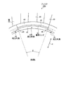
本実施例に係る軸流式空気機械用のブリスクについて、図13〜図15を用いて説明する。図13は、図1のA−A線によるブリスクの部分断面図である。図14は、図13に矢印Eで示す方向から見たブリスクの側面図である。図15は、ロータ回転軸の軸方向外側の側壁が切除された周方向溝の配列パターンの一例を示す図である。
Example 4
A blisk for an axial flow type air machine according to the present embodiment will be described with reference to FIGS. 13 is a partial cross-sectional view of a blisk taken along line AA in FIG. FIG. 14 is a side view of the blisk viewed from the direction indicated by arrow E in FIG. FIG. 15 is a diagram illustrating an example of an array pattern of circumferential grooves in which a side wall on the outer side in the axial direction of the rotor rotation shaft is cut away.
本実施例に係るブリスク10Dは、ロータディスク30に設けられた周方向溝のうち一部は、ロータ回転軸の軸方向外側を構成する側壁が切除されている点で、実施例1と異なり、以下に詳細を説明する。なお、実施例1と略共通の構成については、同一の符号を付して説明を省略する。
The
なお、図13において、一点鎖線Bの右側には、周方向溝の軸方向外側の側壁が切除されており、且つ摩擦部材が周方向溝に挿入された状態を示し、一点鎖線Bの左側には、切除されておらず、且つ摩擦部材が周方向溝に挿入される前の状態を示している。 In FIG. 13, on the right side of the alternate long and short dash line B, the axially outer side wall of the circumferential groove is cut off, and the friction member is inserted into the circumferential groove. Shows a state before being cut off and before the friction member is inserted into the circumferential groove.
図13及び図14に示すように、本実施例に係るブリスク10Dにおいては、ロータディスク30のプラットホーム部33には、ロータ回転軸の軸方向外側に側壁46を有する周方向溝40と、当該側壁46が切除された周方向溝40Dが混在して設けられている。周方向溝40Dは、上述の周方向溝40の側壁46より軸方向外側の部分が全て取り除かれている。すなわち、ブリスク10Dの周方向溝(40,40D)のうち、一部は、側壁46が切り欠かれた周方向溝40Dで構成されている。周方向溝40Dは、プラットホーム部33を構成する外表面のうち、ロータ回転軸の径方向内側にあり、且つ溝底44よりもロータ回転軸の軸方向外側の面35cから、ロータ回転軸の径方向外側に掘り下げられて形成されている。周方向溝40の溝底44は、プラットホーム部33のロータ回転軸の軸方向外側を構成する側面43と接続されている。
As shown in FIGS. 13 and 14, in the
図14及び図15に示すように、側壁46を有する周方向溝40と、側壁46が切除された周方向溝40Dは、ロータ回転軸の周方向に交互に設けられている。側壁46を有する周方向溝40と、側壁46が切除された周方向溝40Dにおいて、ロータ回転軸の軸方向内側の側壁45及び溝底44は、共通の形状となっており、連続するようロータディスク30に形成されている。
As shown in FIGS. 14 and 15, the
側壁が切除された周方向溝40Dは、ロータ回転軸を中心に所定の角度θをなして複数設けられている。側壁46が切除された周方向溝40Dは、ロータ回転軸を中心として非対称なパターンでロータ回転軸の周方向に配列されている。
A plurality of
これにより、翼20が振動し、ブリスク10Dが変形して、周方向溝40及び周方向溝40Dと摩擦リング60との間で相対的な変位が生じると、側壁46を有する周方向溝40と摩擦リング60との間に生じる摩擦力と、側壁46を有しない周方向溝40Dと摩擦リング60との間に生じる摩擦力とを、部位に応じて異なるものにすることができる。側壁46を有しない周方向溝40Dは、ロータ回転軸を中心として非対称なパターンで配列されているため、いわゆるミスチューニング効果を利用してブリスク10Dに固有振動が生じることを抑制することができ、翼20に作用する流体力が当該振動を増幅して、翼20の自励振動いわゆるフラッタが生じることを抑制することができる。
Accordingly, when the
このように本実施例に係るブリスク10Dにおいて、ロータ回転軸の軸方向外側を構成する側壁46が切除された周方向溝40Dと、当該側壁46を有する周方向溝40が混在して設けられているものとしたので、側壁46を有する周方向溝40と摩擦リング60との間に生じる摩擦力と、側壁46が切除された周方向溝40Dと摩擦リング60との間に生じる摩擦力とを、ロータ回転軸の周方向の各部位に応じて異なるものにすることができる。
As described above, in the
また、本実施例に係るブリスク10Dにおいて、側壁46が切除された周方向溝40Dは、ロータ回転軸を中心として非対称なパターンで配列されているものとしたので、ミスチューニング効果を利用してブリスク10Dに固有振動が生じることを抑制することができる。
Further, in the
なお、上述した各実施例において、周方向溝(40;40B;40C)は、ロータ回転軸の周方向に、全周に亘って形成されているものとしたが、これに限定されるものではない。摩擦リング(60;70;70B;80;80B)の形状に応じてC字形状に形成するものとしても良い。 In each of the above-described embodiments, the circumferential groove (40; 40B; 40C) is formed over the entire circumference in the circumferential direction of the rotor rotation shaft, but is not limited thereto. Absent. It is good also as what forms in C shape according to the shape of a friction ring (60; 70; 70B; 80; 80B).
なお、上述した各実施例では、ブリスク(10;10B;10C;10D)には、ロータ回転軸の軸方向の両側に周方向溝が形成されるものとしたが、片側にのみ形成するものとしても良い。 In the above-described embodiments, the blisks (10; 10B; 10C; 10D) are formed with circumferential grooves on both sides in the axial direction of the rotor rotation shaft, but are formed only on one side. Also good.
また、上述した各実施例において、ロータディスク30と接してロータ回転軸の周方向に延びている摩擦部材としての摩擦リング(60;70;70B;80;80B)は、開端を有するC字状に延びているものとしたが、摩擦リングの形状は、これに限定されるものではない。ロータ回転軸の周方向に延びていれば良く、例えば、摩擦リングを、半円の円弧状のものとし、これを同一の周方向溝に複数並べて挿入するものとしても良い。摩擦リングの直径、重量、及び断面形状は、翼20における振動の減衰が最適なものとなるよう適宜設定される。
In each of the above-described embodiments, the friction ring (60; 70; 70B; 80; 80B) serving as a friction member in contact with the
10,10B,10C,10D ブリスク
20 翼
30 ロータディスク
33 プラットホーム部
40,40B,40C,40D 周方向溝
44,44B,44C 周方向溝の溝底
45 軸方向内側の側壁
46 軸方向外側の側壁
47 径方向内側の側壁
48 径方向外側の側壁
60 摩擦リング(摩擦部材)
70,70B 摩擦リング(摩擦部材)
76 コーティング層
80,80B 摩擦リング(摩擦部材)
86 コーティング層
C ロータ回転軸
R ロータ回転軸の径方向
10, 10B, 10C,
70, 70B Friction ring (friction member)
76
86 Coating layer C Rotor rotation shaft R Radial direction of rotor rotation shaft
Claims (4)
ロータ回転軸の周方向に延びており、ロータ回転軸の径方向内側からロータディスクに接して、当該ロータディスクとの間に摩擦を発生可能な摩擦部材を有し、
ロータディスクには、ロータ回転軸の周方向に延びて摩擦部材を挿入可能な周方向溝が形成されており、
ロータディスクのうちロータ回転軸の径方向外側には、径方向内側に比べてロータ回転軸方向の幅が大きく設定されて翼が結合されるプラットホーム部を有し、周方向溝は、当該プラットホーム部に形成されており、
周方向溝は、溝底がロータ回転軸の軸方向外側に面するよう構成されている
ことを特徴とするブリスク。 A blisk used in an axial flow type air machine, in which a blade and a rotor disk constituting a rotor are integrally formed,
It extends in the circumferential direction of the rotor rotation shaft, has a friction member that comes into contact with the rotor disk from the inside in the radial direction of the rotor rotation shaft and can generate friction with the rotor disk,
The rotor disk is formed with a circumferential groove that extends in the circumferential direction of the rotor rotation shaft and into which a friction member can be inserted.
The rotor disk has a platform portion on the radially outer side of the rotor rotation shaft, in which the width in the rotor rotation shaft direction is set larger than that on the radially inner side and the blades are coupled to each other. Is formed,
The circumferential groove is configured so that the groove bottom faces the axially outer side of the rotor rotation shaft.
摩擦部材は、平板状をなしており、ロータ回転軸の径方向外側の側壁に接するよう周方向溝に挿入されている
ことを特徴とするブリスク。 In the blisk of claim 1,
The friction member has a flat plate shape and is inserted into a circumferential groove so as to contact a radially outer side wall of the rotor rotation shaft.
摩擦部材のうち周方向溝と接する面は、弾性材で構成されている
ことを特徴とするブリスク。 In the blisk according to claim 1 or 2,
A blisk characterized in that the surface of the friction member in contact with the circumferential groove is made of an elastic material.
摩擦部材は、開端を有してC字状に延びている摩擦リングである
ことを特徴とするブリスク。 In the blisk according to any one of claims 1 to 3,
The friction member is a friction ring having an open end and extending in a C shape.
Priority Applications (1)
| Application Number | Priority Date | Filing Date | Title |
|---|---|---|---|
| JP2012068356A JP2012122485A (en) | 2012-03-23 | 2012-03-23 | Blisk |
Applications Claiming Priority (1)
| Application Number | Priority Date | Filing Date | Title |
|---|---|---|---|
| JP2012068356A JP2012122485A (en) | 2012-03-23 | 2012-03-23 | Blisk |
Related Parent Applications (1)
| Application Number | Title | Priority Date | Filing Date |
|---|---|---|---|
| JP2008038895A Division JP5030813B2 (en) | 2008-02-20 | 2008-02-20 | Blisk |
Publications (1)
| Publication Number | Publication Date |
|---|---|
| JP2012122485A true JP2012122485A (en) | 2012-06-28 |
Family
ID=46504148
Family Applications (1)
| Application Number | Title | Priority Date | Filing Date |
|---|---|---|---|
| JP2012068356A Pending JP2012122485A (en) | 2012-03-23 | 2012-03-23 | Blisk |
Country Status (1)
| Country | Link |
|---|---|
| JP (1) | JP2012122485A (en) |
Cited By (3)
| Publication number | Priority date | Publication date | Assignee | Title |
|---|---|---|---|---|
| JP2014114716A (en) * | 2012-12-07 | 2014-06-26 | Mitsubishi Heavy Ind Ltd | Blade vibration damping structure |
| CN105179309A (en) * | 2015-06-24 | 2015-12-23 | 上海交通大学 | Compressor blade |
| CN107084010A (en) * | 2016-02-12 | 2017-08-22 | 通用电气公司 | Gas-turbine unit with ring damping piece |
Citations (3)
| Publication number | Priority date | Publication date | Assignee | Title |
|---|---|---|---|---|
| JPS63254264A (en) * | 1987-04-08 | 1988-10-20 | ヘルムート・ペルツエル | Damping means for damping propagation of sound of cycle |
| JPH0539701A (en) * | 1991-08-06 | 1993-02-19 | Fuji Electric Co Ltd | Cascade of turbine moving blade |
| JP2001082544A (en) * | 1999-08-05 | 2001-03-27 | General Electric Co <Ge> | Device and method for damping rotor vibration |
-
2012
- 2012-03-23 JP JP2012068356A patent/JP2012122485A/en active Pending
Patent Citations (3)
| Publication number | Priority date | Publication date | Assignee | Title |
|---|---|---|---|---|
| JPS63254264A (en) * | 1987-04-08 | 1988-10-20 | ヘルムート・ペルツエル | Damping means for damping propagation of sound of cycle |
| JPH0539701A (en) * | 1991-08-06 | 1993-02-19 | Fuji Electric Co Ltd | Cascade of turbine moving blade |
| JP2001082544A (en) * | 1999-08-05 | 2001-03-27 | General Electric Co <Ge> | Device and method for damping rotor vibration |
Cited By (3)
| Publication number | Priority date | Publication date | Assignee | Title |
|---|---|---|---|---|
| JP2014114716A (en) * | 2012-12-07 | 2014-06-26 | Mitsubishi Heavy Ind Ltd | Blade vibration damping structure |
| CN105179309A (en) * | 2015-06-24 | 2015-12-23 | 上海交通大学 | Compressor blade |
| CN107084010A (en) * | 2016-02-12 | 2017-08-22 | 通用电气公司 | Gas-turbine unit with ring damping piece |
Similar Documents
| Publication | Publication Date | Title |
|---|---|---|
| JP5030813B2 (en) | Blisk | |
| JP5005975B2 (en) | Device for damping the vibration of the ring that holds the fan blades of the turbomachine in the axial direction | |
| US7311495B2 (en) | Vane support in a gas turbine engine | |
| JP5702783B2 (en) | Vibration damping shim for fan blades | |
| JP5965616B2 (en) | Turbine blade combination damper and seal pin and related methods | |
| JP5804893B2 (en) | Shaft seal device and rotary machine equipped with the same | |
| JP2007332963A (en) | Rotor blade vibration damper system | |
| US11215062B2 (en) | Blade arrangement with damper for turbomachine | |
| US7572098B1 (en) | Vane ring with a damper | |
| US10138756B2 (en) | Method for damping a gas-turbine blade, and vibration damper for implementing same | |
| JP6214677B2 (en) | Turbomachine rotor blade, turbomachine rotor disk, turbomachine rotor, gas turbine engine having multiple root and slot contact face angles | |
| JP2012122485A (en) | Blisk | |
| WO2015137393A1 (en) | Shroud, moving blade element, and rotary machine | |
| JP6479328B2 (en) | Rotor and rotary machine | |
| JP2015155683A (en) | Moving blade body and rotary machine | |
| JP2009167882A (en) | Centrifugal impeller | |
| JP7269029B2 (en) | Blades and rotating machinery | |
| JP6257991B2 (en) | Rotor blade and rotating machine | |
| JP6936126B2 (en) | Impeller, rotating machine | |
| JP6625456B2 (en) | Turbine blade assembly | |
| JP2000337103A (en) | Integral shroud stationary blade | |
| JP6991896B2 (en) | Blades, rotary machines | |
| JP7235536B2 (en) | rotating machinery | |
| JP2003097216A (en) | Damping mechanism of rotor blade | |
| JP5484948B2 (en) | Rotating fluid machine |
Legal Events
| Date | Code | Title | Description |
|---|---|---|---|
| A621 | Written request for application examination |
Free format text: JAPANESE INTERMEDIATE CODE: A621 Effective date: 20120323 |
|
| A977 | Report on retrieval |
Free format text: JAPANESE INTERMEDIATE CODE: A971007 Effective date: 20130214 |
|
| A131 | Notification of reasons for refusal |
Free format text: JAPANESE INTERMEDIATE CODE: A131 Effective date: 20130219 |
|
| A02 | Decision of refusal |
Free format text: JAPANESE INTERMEDIATE CODE: A02 Effective date: 20130521 |