JP2012122380A - Bellows pump - Google Patents
Bellows pump Download PDFInfo
- Publication number
- JP2012122380A JP2012122380A JP2010272815A JP2010272815A JP2012122380A JP 2012122380 A JP2012122380 A JP 2012122380A JP 2010272815 A JP2010272815 A JP 2010272815A JP 2010272815 A JP2010272815 A JP 2010272815A JP 2012122380 A JP2012122380 A JP 2012122380A
- Authority
- JP
- Japan
- Prior art keywords
- bellows
- pump head
- passage
- pump
- valve
- Prior art date
- Legal status (The legal status is an assumption and is not a legal conclusion. Google has not performed a legal analysis and makes no representation as to the accuracy of the status listed.)
- Granted
Links
Images


Abstract
Description
本発明は、ベローズポンプに関する。 The present invention relates to a bellows pump.
半導体製造や化学工業等において、薬液や溶剤等の流体を送給させるためのポンプとして、ベローズポンプが使用される場合がある。
このベローズポンプは、例えば、特許文献1及び2に記載されているように、ポンプヘッドの左右方向(水平方向)の両側にポンプケースを連結して2つの空気室を形成し、各空気室の内部にそれぞれ左右方向に伸縮可能なベローズを設け、各空気室に交互に加圧エアを供給することによって各ベローズを収縮又は伸張させるように構成されている。
In semiconductor manufacturing, chemical industry, etc., a bellows pump may be used as a pump for feeding fluids such as chemicals and solvents.
In this bellows pump, for example, as described in
ポンプヘッドには、ベローズの内部と連通する流体の吸込通路と吐出通路とが形成され、さらに、吸込通路及び吐出通路に対する一方向への流体の流れを許容し、他方向への流体の流れを阻止するチェックバルブが設けられている。吸込通路用のチェックバルブは、ベローズの伸張により開くことによって吸込通路からベローズ内への流体の流れを許容し、ベローズの収縮により閉じることによって、当該ベローズ内から吸込通路への流体の流れを阻止するように構成されている。また、吐出通路用のチェックバルブは、ベローズの伸張により閉じることによって、吐出通路からベローズ内への流体の流れを阻止し、ベローズの収縮により開くことによって、ベローズ内から吐出通路への流体の流れを許容するように構成されている。 The pump head is formed with a fluid suction passage and a discharge passage communicating with the inside of the bellows, and further allows a fluid flow in one direction with respect to the suction passage and the discharge passage, and allows a fluid flow in the other direction. A check valve is provided for blocking. The check valve for the suction passage allows the flow of fluid from the suction passage into the bellows by being opened by the extension of the bellows, and blocks the flow of fluid from the inside of the bellows to the suction passage by being closed by the contraction of the bellows. Is configured to do. The check valve for the discharge passage is closed by the extension of the bellows to prevent the flow of fluid from the discharge passage into the bellows, and is opened by the contraction of the bellows, so that the fluid flow from the inside of the bellows to the discharge passage Is configured to allow.
また、特許文献1及び2に記載のチェックバルブは、いずれも弁体がバルブケース内でベローズの伸縮方向(左右方向)に移動するように配置されている。そして、特許文献1に記載されているチェックバルブは、弁体が圧縮コイルバネによって閉弁方向に付勢され、特許文献2に記載のチェックバルブは、弁体がボールにより構成されるとともに、ベローズの伸縮に伴う流体の流れによって移動し、開閉を行う。
The check valves described in
特許文献1に記載されているチェックバルブは、弁体が圧縮コイルバネによって付勢されているので、シール性が高く、ベローズの伸縮に伴う動作、特にチェックバルブの開から閉への切り替え動作を、ベローズの伸縮に伴う流体の流れによる背圧に加え、圧縮コイルバネの付勢力によって応答性よく行うことができる。しかし、圧縮コイルバネの伸縮ストロークを確保する必要があるため、バルブケースの水平方向寸法を大きくする必要がある。バルブケースは、ベローズ内に配置されるため、バルブケースの水平方向寸法が大きくなると、その分ベローズを水平方向に長く形成する必要が生じ、ベローズポンプ全体が大型化するという欠点がある。
また、圧縮コイルバネは、PTFE等の合成樹脂により形成されているので、長期使用によるクリープ等によってシール精度が低下する可能性がある。
The check valve described in
In addition, since the compression coil spring is formed of a synthetic resin such as PTFE, there is a possibility that the sealing accuracy may be lowered due to creep or the like due to long-term use.
これに対して、特許文献2に記載のチェックバルブは、圧縮コイルバネを使用していないため、バルブケースの水平方向寸法をある程度は小さくすることができ、ベローズポンプの小型化に寄与することができるとともに、クリープ等に起因するシール精度の低下を防止することができる。
しかしながら、弁体(ボール)が、ベローズの伸縮に伴う流体の流れのみによって移動するため、圧縮コイルバネを備えたものと比較して、特に、チェックバルブの開から閉への切り換えに遅れを生じやすくなるという欠点がある。また、ベローズポンプの運転を停止したときに、閉弁の遅れに起因して、吐出通路からベローズ内に、またベローズ内から吸込通路内に流体が逆流しやすくなるという欠点がある。このような流体の逆流は、ベローズポンプの運転を再開したときの定量性を損なう原因となる。また、バルブケース内に弁体を収容するスペースが必要であるため、バルブケースの左右方向寸法を小さくするにも限界がある。
On the other hand, since the check valve described in Patent Document 2 does not use a compression coil spring, the horizontal dimension of the valve case can be reduced to some extent, which can contribute to the downsizing of the bellows pump. At the same time, it is possible to prevent a decrease in sealing accuracy due to creep or the like.
However, since the valve body (ball) moves only by the flow of the fluid accompanying expansion and contraction of the bellows, it is particularly easy to cause a delay in switching the check valve from opening to closing, compared to the one having a compression coil spring. There is a drawback of becoming. Further, when the operation of the bellows pump is stopped, there is a drawback that the fluid easily flows backward from the discharge passage into the bellows and from the inside of the bellows into the suction passage due to a delay in valve closing. Such a reverse flow of the fluid causes a loss of quantitativeness when the operation of the bellows pump is resumed. In addition, since a space for accommodating the valve body is required in the valve case, there is a limit to reducing the lateral dimension of the valve case.
本発明は、ベローズポンプの小型化や長期にわたるチェックバルブのシール精度の維持を可能としながら、ベローズの伸縮に応じて応答性よくチェックバルブの開閉動作を行うことができるベローズポンプを提供することを目的とする。 The present invention provides a bellows pump that can open and close the check valve with high responsiveness according to the expansion and contraction of the bellows, while enabling the bellows pump to be downsized and maintaining the sealing accuracy of the check valve over a long period of time. Objective.
本発明のベローズポンプは、流体の流路が形成されたポンプヘッドと、このポンプヘッドに取り付けられ、その内部が前記流路に連通する水平方向に伸縮自在なベローズと、前記流路に対する一方向への流体の流れを許容し、他方向への流体の流れを阻止するチェックバルブと、を備えているベローズポンプであって、
前記チェックバルブは、前記ポンプヘッド内に収容されるとともに、自重によって閉弁方向へ移動可能な弁体と、前記ポンプヘッドに取り付けられるとともに、前記弁体が前記ポンプヘッド内から離脱するのを阻止するキャップ部材と、を備えていることを特徴とする。
The bellows pump of the present invention includes a pump head in which a fluid flow path is formed, a bellows attached to the pump head, the inside of which communicates with the flow path, and which can be expanded and contracted in the horizontal direction. A check valve that allows fluid flow to and prevents fluid flow in the other direction,
The check valve is housed in the pump head, and is movable to the valve closing direction by its own weight, and is attached to the pump head, and prevents the valve body from being detached from the pump head. And a cap member.
本発明によれば、チェックバルブの弁体が自重によって閉弁方向に移動可能であるので、圧縮コイルバネによる付勢がなくてもベローズの伸縮に伴う流体の流れに応じて開閉動作、特に開から閉への動作を迅速に行うことができ、ベローズポンプを停止した場合にも、流体の逆流を適切に防止することができる。また、圧縮コイルバネを備える必要がなく、しかも弁体がポンプヘッド内に収容されているので、チェックバルブの水平方向の寸法を小さくすることができ、ベローズポンプの小型化が可能になるとともに、圧縮コイルバネのクリープに起因してシール精度が低下するといった問題も生じることがない。 According to the present invention, since the valve body of the check valve can move in the valve closing direction by its own weight, the opening / closing operation according to the flow of the fluid accompanying the expansion / contraction of the bellows, in particular, from the opening even without urging by the compression coil spring. The closing operation can be performed quickly, and even when the bellows pump is stopped, the backflow of the fluid can be appropriately prevented. Further, since it is not necessary to provide a compression coil spring and the valve body is accommodated in the pump head, the horizontal dimension of the check valve can be reduced, the size of the bellows pump can be reduced, and the compression can be performed. There is no problem that the sealing accuracy is lowered due to the creep of the coil spring.
前記ポンプヘッドには、前記弁体が移動可能に収容されると共に、閉弁のための前記弁体の移動方向が低位となるように水平方向に対して傾斜する移動通路が形成されていることが好ましい。これにより移動通路に沿って弁体を閉弁方向に自重で移動させることができる。 In the pump head, the valve body is movably accommodated, and a moving passage that is inclined with respect to the horizontal direction is formed so that the moving direction of the valve body for closing the valve is low. Is preferred. Thereby, the valve body can be moved by its own weight in the valve closing direction along the movement path.
前記弁体は、前記移動通路に沿って転動可能な球体であってもよいし、前記移動通路に沿って転動可能な円柱体であってもよい。
いずれにおいても移動通路内で円滑に弁体を移動させることができる。
The valve body may be a sphere that can roll along the movement path, or a cylinder that can roll along the movement path.
In any case, the valve body can be smoothly moved in the moving passage.
本発明によれば、ベローズポンプの小型化や長期にわたるチェックバルブのシール精度の維持を可能としながら、ベローズの伸縮に応じて応答性よくチェックバルブの開閉動作を行うことができる。 According to the present invention, the check valve can be opened and closed with high responsiveness according to the expansion and contraction of the bellows, while the bellows pump can be downsized and the seal accuracy of the check valve can be maintained over a long period of time.
以下、本発明の実施形態を図面に基づいて説明する。
《ベローズポンプの全体構成》
図1は、本発明の実施形態に係るベローズポンプの断面図である。
本実施形態のベローズポンプ10は、薬液や溶剤等の移送流体を一定量供給するときに用いられ、ポンプヘッド11と、このポンプヘッド11の左右方向(水平方向)の両側に取り付けられる一対のポンプケース12と、各ポンプケース12の内部において、ポンプヘッド11の左右方向の側面に取り付けられる一対のベローズ13と、一対のベローズ13の内部において、ポンプヘッド11の左右方向の側面に取り付けられる計4個のチェックバルブ38,40と、を備えている。
Hereinafter, embodiments of the present invention will be described with reference to the drawings.
<Overall configuration of bellows pump>
FIG. 1 is a cross-sectional view of a bellows pump according to an embodiment of the present invention.
The
《ポンプケースの構成》
ポンプケース12は、ポンプヘッド11の左右両側に固定された筒形状のケース胴体15と、このケース胴体15の左右方向の一端部(ポンプヘッド11とは反対側の端部)を閉鎖する閉鎖蓋16と、を備えている。ケース胴体15と、ポンプヘッド11及び閉鎖蓋16との接合端面にはシール部材が介装されており、これらの部材によって囲まれた空間が気密状態が保持された空気室17とされている。
<Configuration of pump case>
The
閉鎖蓋16には吸排気ポート19が設けられており、この吸排気ポート19は、切換バルブ18を介してエアコンプレッサ等の空気供給装置(駆動装置)20に接続されている。
また、閉鎖蓋16には、近接センサからなる検出センサ21が取り付けられており、この検出センサ21は、ベローズ13に取り付けられた作動板24を検知して、当該ベローズ13の伸縮状態を検出する。
The
In addition, a
《ベローズの構成》
ベローズ13は、PTFEやPFA等のフッ素樹脂により有底筒形状に形成され、ベローズ13の開放側端部はポンプヘッド11に固定されている。具体的に、ベローズ13の開放側端部には周溝22が形成され、ポンプヘッド11とポンプケース12との間には、径方向内方へ突出する係止環23が固定され、この係止環23を周溝22に嵌合することによってベローズ13がポンプヘッド11に固定されている。
<Composition of bellows>
The
ベローズ13の周壁は蛇腹形状に形成されて水平方向に伸縮可能に構成されている。また、ベローズ13の底部の外面は、作動板24によって覆われている。具体的には、ベローズ13の底部の外周部には周溝25が形成されており、作動板24の外周部に固定された係止環26を周溝25に嵌合させることによって作動板24がベローズ13の底部に固定されている。
The peripheral wall of the
一対のベローズ13のそれぞれに固定された作動板24は、連動シャフト28によって連結されている。この連動シャフト28は、その長手方向の中途部がポンプヘッド11に形成されたガイド部29に左右方向摺動可能にガイドされており、その両端部が作動板24の外周部にナット等の連結具30によって固定されている。そして、一対のベローズ13は、一方が伸張したときに他方が収縮し、一方が収縮したときに他方が伸張するように連動シャフト28によって連動される。
The
空気供給装置20によって生成された適当な圧力の空気は、各ポンプケース12の閉鎖蓋16に設けられた吸排気ポート19を介して2つの空気室17に対して交互に供給される。一方の空気室17に空気が供給されると、当該空気室17内に配置されたベローズ13が収縮し、このベローズ13の収縮に連動して他方のベローズ13が伸張する。そして、他方のベローズ13の作動板24が検出センサ21によって検出されると、空気供給装置20によって生成された空気は、切り換えバルブ18によって他方の吸排気ポート19から他方の空気室17に供給される。これによって、他方のベローズ13が収縮するとともに一方のベローズ13が伸張する。このようなベローズ13の伸縮に伴って、ベローズ13の内部への流体の吸込と吐出とが交互に行われ、当該流体を移送可能となっている。
Air of appropriate pressure generated by the
《ポンプヘッドの構成》
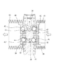
図2は、ポンプヘッド及びチェックバルブを示す断面図、図3は、ポンプヘッド及びチェックバルブを示す斜視図である。
ポンプヘッド11は、PTFEやPFA等のフッ素樹脂から形成されている。ポンプヘッド11の内部には、吸込通路33及び吐出通路34(本発明の流路)が形成されている。この吸込通路33及び吐出通路34は、図3に示すように、ポンプヘッド11の外周面において開口する主通路33A,34Aを有し、この主通路33A,34Aには、当該外周面に設けられた吸込ポート及び吐出ポート(いずれも図示略)に接続される。吸込ポートは流体の貯留タンク等に接続され、吐出ポートは流体の移送先に接続される。
<Configuration of pump head>
FIG. 2 is a sectional view showing the pump head and the check valve, and FIG. 3 is a perspective view showing the pump head and the check valve.
The
また、図2に示すように、吸込通路33及び吐出通路34は、それぞれ主通路33A,34Aからポンプヘッド11の左右両側面に向けて分岐する分岐通路33B,34Bを有し、各分岐通路33B,34Bは、ポンプヘッド11の左右両側面において開口している。そして各分岐通路33B,34Bは、それぞれチェックバルブ38,40を介してベローズ13の内部と連通している。
As shown in FIG. 2, the
図4(a)は、ポンプヘッドに形成された吸込通路及び移動通路の拡大正面断面図、図4(b)は吸込通路及び移動通路の拡大側面図である。
吸込通路33の分岐通路33Bは、主通路33Aに連なる第1分岐通路33B1と、ポンプヘッド11の側面11Aに凹設された3個の第2分岐通路33B2とからなる。第1分岐通路33B1は、ポンプヘッド11の側面11Aから離れるほど低位となるように水平方向に対して傾斜している。また、第1分岐通路33B1は、ポンプヘッド11の側面11Aに凹設された移動通路53に連通している。この移動通路53は、チェックバルブ38の弁体45が収容されるものであり、その詳細については後述する。
FIG. 4A is an enlarged front sectional view of the suction passage and the moving passage formed in the pump head, and FIG. 4B is an enlarged side view of the suction passage and the moving passage.
The branch passage 33B of the
第1分岐通路33B1は、移動通路53よりも小径であり、この移動通路53との接続部には、テーパー部66が形成されている。このテーパー部66は、弁体45が嵌合する弁座として機能する。
The
図4(b)に示すように、3個の第2分岐通路33B2は、側面視で移動通路53を中心として周方向に等配(三角配置)されている。また、図4(a)に示すように、第2分岐通路33B2は、第1分岐通路33B1には到らない深さでポンプヘッド11の側面11Aに水平方向に凹設されている。3個の第2分岐通路33B2は、その一部が移動通路53に重複し、連通しているので、この移動通路53を介して第1分岐通路33B1にも連通している。そのため、移動通路53も吸込通路33の一部を構成することになる。
As shown in FIG. 4B, the three second branch passages 33B2 are equally arranged (triangular arrangement) in the circumferential direction around the
ポンプヘッド11の側面11Aの第2分岐通路33B2の周囲には、後述するチェックバルブ38のキャップ部材44を取り付けるための円環状の凹溝41が形成されている。この凹溝41内の外側周面には雌ネジ42が形成されている。
Around the second branch passage 33B2 on the
図5(a)は、ポンプヘッドに形成された吐出通路及び移動通路の正面断面図、図5(b)は吐出通路及び移動通路の側面図である。
吐出通路34の分岐通路34Bは、3個形成されており、いずれも、ポンプヘッド11の側面11Aから水平方向に凹設され、主通路34Aに連通している。また、分岐通路34Bは、図5(b)に示すように側面視で三角配置されている。三角配置された3個の分岐通路34Bの中心位置には移動通路53が凹設され、この移動通路53内にチェックバルブ40の弁体45が収容されている。このチェックバルブ40の詳細についても後述する。
FIG. 5A is a front sectional view of the discharge passage and the movement passage formed in the pump head, and FIG. 5B is a side view of the discharge passage and the movement passage.
Three
ポンプヘッド11の側面11Aの分岐通路34Bの周囲には、チェックバルブ40のキャップ部材46を取り付けるための円環状の凹溝41が形成されている。この凹溝41内の外側周面には雌ネジ42が形成されている。
Around the
《チェックバルブの構成》
図1に示すように、ポンプヘッド11の側面11Aには、吸込通路33及び吐出通路34における一方向への流体の流通を許容し、他方向への流体の流通を阻止するチェックバルブ38,40が設けられている。
《Check valve configuration》
As shown in FIG. 1, on the
吸込通路33用のチェックバルブ38(以下、「吸込用チェックバルブ」ともいう)は、自身が配置されているベローズ13が伸張したときに開弁して、吸込通路33からベローズ13内部への流体の吸引を許容し、当該ベローズ13が収縮したときに閉弁して、ベローズ13内部から吸込通路33への流体の逆流を阻止する。
The
また、吐出通路34用のチェックバルブ40(以下、「吐出用チェックバルブ」ともいう)は、自身が配置されているベローズ13が収縮したときに開弁して、ベローズ13内部から吐出通路34への流体の流出を許容し、当該ベローズ13が伸張したときに閉弁して、吐出通路34からベローズ13内部への流体の逆流を阻止する。
Further, the
図2に示すように、吸込用チェックバルブ38は、キャップ部材44と弁体45とを有している。
図6(a)は、吸込用チェックバルブのキャップ部材の正面断面図、(b)は、同キャップ部材の側面図である。キャップ部材44は、円筒部44Aと、底部44Bとから有底円筒形状に形成されている。円筒部44Aの外周面には雄ネジ44Cが形成されており、この雄ネジ44Cは、図2及び図4に示すように、ポンプヘッド11の側面11Aに形成された凹溝41の雌ネジ42に螺合される。これにより、ポンプヘッド11にキャップ部材44が取り付けられる。また、ポンプヘッド11に取り付けられたキャップ部材44の底部44Bは、ポンプヘッド11の側面11Aと間隔をあけて配置される。
As shown in FIG. 2, the
Fig.6 (a) is front sectional drawing of the cap member of the check valve for suction, (b) is a side view of the cap member. The
図6に示すように、キャップ部材44の底部44Bには、4個の連通孔44Dが形成されている。この連通孔44Dは、吸込通路33とベローズ13の内部とを連通する機能を有している。
As shown in FIG. 6, four
図2及び図4に示すように、弁体45は球体(ボール)から構成され、吸込通路33の第1,第2分岐通路33B1,33B2と重複して形成された移動通路53内に配置されている。
移動通路53は、吸込通路33の第1分岐通路33B1と略同一の傾斜角度で傾斜している。すなわち、移動通路53は、ポンプヘッド11の側面11Aから離れるほど低位となるように水平方向に対して傾斜している。したがって、この移動通路53に配置された弁体34は、流体からの圧力を受けていない状態で傾斜に沿って低位側に転動し、第1分岐通路33B1と移動通路53との境界に形成された弁座66に嵌合する。つまり、弁体45は、その自重によって吸引用チェックバルブ38の閉方向へ移動する。また、弁体45は、キャップ部材44によって移動通路53からの離脱が阻止されている。
As shown in FIGS. 2 and 4, the
The
図2に示すように、吐出用チェックバルブ40は、キャップ部材46と弁体45とを有している。
図7は、吐出用チェックバルブのキャップ部材の正面断面図である。キャップ部材46は、円筒部46Aと底部46Bとから有底円筒状に形成されている。また、円筒部46Aの外周面には雄ネジ46Cが形成されており、この雄ネジ46Cは、図2及び図5に示すようにポンプヘッド11の側面11Aに形成された凹溝41の雌ネジ42に螺合される。これにより、ポンプヘッド11にキャップ部材46が取り付けられる。また、ポンプヘッド11に取り付けられたキャップ部材46の底部46Bは、ポンプヘッド11の側面11Aにほぼ密着される。
As shown in FIG. 2, the
FIG. 7 is a front sectional view of the cap member of the discharge check valve. The
キャップ部材46の底部46Bの中心には1個の連通孔46Dが形成されている。この連通孔46Dは、吐出通路34とベローズ13の内部とを連通する機能を有している。また、底部46Bの内面の連通孔46Dの周囲にはテーパー部67が形成されている。このテーパー部67は弁体45が嵌合する弁座として機能する。
One
図2及び図5に示すように、弁体45は、吸引用チェックバルブ38の弁体45と同様の球体(ボール)から構成され、吐出通路34の分岐通路34Bと重複して形成された移動通路53内に配置されている。移動通路53は、ポンプヘッド11の側面11Aに近づくほど低位となるように水平方向に対して傾斜している。したがって、この移動通路53に配置された弁体34は、流体からの圧力を受けていない状態で傾斜に沿って低位側に転動し、キャップ部材46に形成された弁座67に嵌合する。すなわち、弁体45は、その自重によって吐出用チェックバルブ38の閉方向へ移動する。また、弁体45は、キャップ部材46によって移動通路53からの離脱が阻止される。
なお、図2には、全て閉じた状態のチェックバルブ38,40が示されている。
As shown in FIGS. 2 and 5, the
FIG. 2 shows the
《ベローズポンプの作用》
次に、本実施形態のベローズポンプ10の作用を図8及び図9を参照して説明する。なお、図8及び図9においてはベローズ13の構成を簡略化して示している。
図8に示すように、左側のベローズ13が収縮し、右側のベローズ13が伸張した場合、ポンプヘッド11の左側面に装着された吐出用チェックバルブ40と吸込用チェックバルブ38の各弁体45は、左側のベローズ13内の流体から圧力を受けて移動通路53内を右側に移動する。これにより吐出用チェックバルブ40が開くとともに、吸込用チェックバルブ38が閉じ、左側のベローズ13内の流体が吐出通路34からポンプ外へ排出される。
<Operation of bellows pump>
Next, the operation of the bellows pump 10 of this embodiment will be described with reference to FIGS. In addition, in FIG.8 and FIG.9, the structure of the
As shown in FIG. 8, when the left bellows 13 contracts and the right bellows 13 expands, the
ポンプヘッド11の右側面に装着された吐出用チェックバルブ40と吸込用チェックバルブ38の各弁体45は、右側のベローズ13による吸引作用によって移動通路53内を右側に移動する。これにより吸込用チェックバルブ38が開くとともに、吐出用チェックバルブ40が閉じ、吸込通路33から右側のベローズ13内に流体が吸い込まれる。
The
次に、図9に示すように、右側のベローズ13が収縮し、左側のベローズ13が伸張した場合、ポンプヘッド11の右側面に装着された吐出用チェックバルブ40と吸込用チェックバルブ38の各弁体45は、右側のベローズ13内の流体から圧力を受けて移動通路53内を左側に移動する。これにより吐出用チェックバルブ40が開くとともに、吸込用チェックバルブ38が閉じ、右側のベローズ13内の流体が吐出通路34からポンプ外へ排出される。
Next, as shown in FIG. 9, when the right bellows 13 contracts and the left bellows 13 expands, each of the
ポンプヘッド11の左側面に装着された吐出用チェックバルブ40と吸込用チェックバルブ38の各弁体45は、左側のベローズ13による吸引作用によって移動通路53内を左側に移動する。これにより吸込用チェックバルブ38が開くとともに、吐出用チェックバルブ40が閉じ、吸込通路33から左側のベローズ13内に流体が吸引される。
The
以上の動作を繰り返し行うことで、左右のベローズ13は、交互に流体の吸引と排出とを行い、ベローズ13の容積とストローク回数とによって規定される容量の流体を移送することができる。
By repeating the above operation, the left and right bellows 13 alternately suck and discharge the fluid, and can transfer a fluid having a capacity defined by the volume of the
《本実施形態の作用効果》
本実施形態において、チェックバルブ38,40の弁体45は、移動通路53の傾斜に沿ってその自重によりチェックバルブを閉じる方向(閉弁方向)に移動するように構成されている。そのため、ベローズ13の伸縮に応じた流体の流れに応答性よく追従し、特に、開から閉への動作を迅速に行うことができる。そのため、閉弁の遅れに起因する流体の逆流を防止することができる。したがって、ベローズポンプ10の運転を停止した場合には、吐出通路34からベローズ13内への流体の逆流や、ベローズ13内から吸込通路33への流体の逆流を好適に抑制することができる。これにより、ベローズポンプ10の運転を再開したときの定量性を確実に確保することができる。
<< Effects of this embodiment >>
In the present embodiment, the
また、本実施形態のチェックバルブ38,40は、従来技術のように圧縮コイルバネを使用していないので、当該圧縮コイルバネのクリープによるシール精度の低下を招くことがない。また、圧縮コイルバネを使用していないので、当該圧縮コイルバネの伸縮ストロークを確保する必要が無く、チェックバルブ38,40を左右方向に短く形成することができる。
In addition, since the
また、本実施形態では、チェックバルブ38,40の弁体45を収容する移動通路が、チェックバルブ38,40そのものではなくポンプヘッド11に形成されているので、チェックバルブ38,40を左右方向に短く形成することができる。
In the present embodiment, since the moving passage for accommodating the
チェックバルブ38,40を左右方向に短くすると、ベローズ13を左右方向に短く(ベローズ13の蛇腹の山の数を少なく)しても、ベローズ13の底部とチェックバルブ38,40とが干渉する可能性が低くなるので、ベローズポンプ10の小型化が可能となる。また、ベローズ13を短くすることによって、より廉価なベローズポンプ10とすることができる。
If the
チェックバルブ38,40は、弁体45とキャップ部材44,46との2部品からなるので、少ない部品点数で安価に構成することができる。
また、チェックバルブ38,40に対して傾斜した移動通路が形成されている場合、移動通路の傾斜方向を正確に合わせながらチェックバルブ38,40をポンプヘッド11に取り付けなければならないが、本実施形態では、移動通路の傾斜方向を意識することなく容易にチェックバルブ38,40をポンプヘッド11に取り付けることができる。したがって、ベローズポンプ10の組立性を向上することができる。
Since the
Further, when the moving passage inclined with respect to the
以上のような、チェックバルブ38,40の部品点数減、ベローズポンプ10の組立性向上により、素材使用量、加工費、組立工数が減り、全体としてベローズポンプ10の製造コストを低減することが可能となる。
By reducing the number of parts of the
また、本実施形態では、弁体45が球体により構成されているので、移動通路53内の移動、特に自重による移動が円滑になされ、ベローズ13の伸縮に応じた流体の流れに対する応答性をより高めることができる。
なお、弁体45は、球体によって構成するに限らず、移動通路53の傾斜に沿って移動可能であれば他の形態によって構成してもよい。例えば、弁体45は、円筒体(円柱体)によって構成することができる。
Further, in the present embodiment, since the
The
本発明は、上記実施形態に限定されるものではなく、特許請求の範囲に記載された発明の範囲内で適宜変更することができる。 The present invention is not limited to the above-described embodiment, and can be appropriately changed within the scope of the invention described in the claims.
10: ベローズポンプ
11: ポンプヘッド
13: ベローズ
33: 吸込通路(流路)
34: 吐出通路(流路)
38: 吸込用チェックバルブ
40: 吐出用チェックバルブ
44: キャップ部材
45: 弁体
46: キャップ部材
53: 移動通路
10: Bellows pump 11: Pump head 13: Bellows 33: Suction passage (flow path)
34: Discharge passage (flow path)
38: Check valve for suction 40: Check valve for discharge 44: Cap member 45: Valve element 46: Cap member 53: Movement passage
Claims (4)
前記チェックバルブは、前記ポンプヘッド内に収容されるとともに、自重によって閉弁方向へ移動可能な弁体と、前記ポンプヘッドに取り付けられるとともに、前記弁体が前記ポンプヘッド内から離脱するのを阻止するキャップ部材と、を備えていることを特徴とするベローズポンプ。 A pump head in which a fluid flow path is formed, a bellows which is attached to the pump head and communicates with the flow path in the horizontal direction, and allows fluid flow in one direction with respect to the flow path. And a check valve for preventing fluid flow in the other direction,
The check valve is housed in the pump head, and is movable to the valve closing direction by its own weight, and is attached to the pump head, and prevents the valve body from being detached from the pump head. A bellows pump.
Priority Applications (1)
| Application Number | Priority Date | Filing Date | Title |
|---|---|---|---|
| JP2010272815A JP5559020B2 (en) | 2010-12-07 | 2010-12-07 | Bellows pump |
Applications Claiming Priority (1)
| Application Number | Priority Date | Filing Date | Title |
|---|---|---|---|
| JP2010272815A JP5559020B2 (en) | 2010-12-07 | 2010-12-07 | Bellows pump |
Publications (2)
| Publication Number | Publication Date |
|---|---|
| JP2012122380A true JP2012122380A (en) | 2012-06-28 |
| JP5559020B2 JP5559020B2 (en) | 2014-07-23 |
Family
ID=46504084
Family Applications (1)
| Application Number | Title | Priority Date | Filing Date |
|---|---|---|---|
| JP2010272815A Active JP5559020B2 (en) | 2010-12-07 | 2010-12-07 | Bellows pump |
Country Status (1)
| Country | Link |
|---|---|
| JP (1) | JP5559020B2 (en) |
Cited By (2)
| Publication number | Priority date | Publication date | Assignee | Title |
|---|---|---|---|---|
| EP2706235A1 (en) | 2012-09-10 | 2014-03-12 | Nippon Pillar Packing Co., Ltd. | Bellows pump |
| WO2024053158A1 (en) * | 2022-09-08 | 2024-03-14 | 日本ピラー工業株式会社 | Bellows pump |
Citations (2)
| Publication number | Priority date | Publication date | Assignee | Title |
|---|---|---|---|---|
| JPS62175281U (en) * | 1986-04-26 | 1987-11-07 | ||
| JP2011256830A (en) * | 2010-06-11 | 2011-12-22 | Nippon Pillar Packing Co Ltd | Bellows pump and check valve |
-
2010
- 2010-12-07 JP JP2010272815A patent/JP5559020B2/en active Active
Patent Citations (2)
| Publication number | Priority date | Publication date | Assignee | Title |
|---|---|---|---|---|
| JPS62175281U (en) * | 1986-04-26 | 1987-11-07 | ||
| JP2011256830A (en) * | 2010-06-11 | 2011-12-22 | Nippon Pillar Packing Co Ltd | Bellows pump and check valve |
Cited By (2)
| Publication number | Priority date | Publication date | Assignee | Title |
|---|---|---|---|---|
| EP2706235A1 (en) | 2012-09-10 | 2014-03-12 | Nippon Pillar Packing Co., Ltd. | Bellows pump |
| WO2024053158A1 (en) * | 2022-09-08 | 2024-03-14 | 日本ピラー工業株式会社 | Bellows pump |
Also Published As
| Publication number | Publication date |
|---|---|
| JP5559020B2 (en) | 2014-07-23 |
Similar Documents
| Publication | Publication Date | Title |
|---|---|---|
| JP6873991B2 (en) | Fluid control valve and fluid control valve manufacturing method | |
| US20130020519A1 (en) | Dual piston actuator and method of use | |
| JP2011043177A5 (en) | ||
| JP5710611B2 (en) | Dispensing pump | |
| US20170051738A1 (en) | Packing stacks for piston pumps | |
| US20140072465A1 (en) | Bellows Pump | |
| JP5559020B2 (en) | Bellows pump | |
| TWI698607B (en) | Gate valve | |
| JP5973197B2 (en) | Piston-type working fluid pressure actuator and control valve | |
| KR102307310B1 (en) | Check valve and liquid supply device equipped with check valve | |
| RU2750568C2 (en) | Valve | |
| JP5680344B2 (en) | Bellows pump and check valve | |
| JP2016217383A5 (en) | High pressure pump | |
| JP4860506B2 (en) | Control valve | |
| US10451093B2 (en) | Fluid pressure cylinder | |
| JP2015203382A (en) | hand pump | |
| JP2015055225A (en) | Constant delivery pump | |
| JP2007100554A (en) | Reciprocating pump | |
| US20160377071A1 (en) | Fluid apparatus | |
| JP5068344B2 (en) | pump | |
| US20220307600A1 (en) | Shaft sealing structure | |
| JP6837290B2 (en) | Air actuator | |
| JP6043626B2 (en) | Bellows pump | |
| EP3460260A1 (en) | Linear hydraulic actuator | |
| JP3742791B2 (en) | pump |
Legal Events
| Date | Code | Title | Description |
|---|---|---|---|
| A621 | Written request for application examination |
Free format text: JAPANESE INTERMEDIATE CODE: A621 Effective date: 20130531 |
|
| A977 | Report on retrieval |
Free format text: JAPANESE INTERMEDIATE CODE: A971007 Effective date: 20140226 |
|
| A131 | Notification of reasons for refusal |
Free format text: JAPANESE INTERMEDIATE CODE: A131 Effective date: 20140311 |
|
| A521 | Written amendment |
Free format text: JAPANESE INTERMEDIATE CODE: A523 Effective date: 20140502 |
|
| TRDD | Decision of grant or rejection written | ||
| A01 | Written decision to grant a patent or to grant a registration (utility model) |
Free format text: JAPANESE INTERMEDIATE CODE: A01 Effective date: 20140603 |
|
| A61 | First payment of annual fees (during grant procedure) |
Free format text: JAPANESE INTERMEDIATE CODE: A61 Effective date: 20140605 |
|
| R150 | Certificate of patent or registration of utility model |
Ref document number: 5559020 Country of ref document: JP Free format text: JAPANESE INTERMEDIATE CODE: R150 |