JP2012120870A - Instrument for setting acetabular cup - Google Patents
Instrument for setting acetabular cup Download PDFInfo
- Publication number
- JP2012120870A JP2012120870A JP2012035576A JP2012035576A JP2012120870A JP 2012120870 A JP2012120870 A JP 2012120870A JP 2012035576 A JP2012035576 A JP 2012035576A JP 2012035576 A JP2012035576 A JP 2012035576A JP 2012120870 A JP2012120870 A JP 2012120870A
- Authority
- JP
- Japan
- Prior art keywords
- adapter
- cup
- impactor
- annular
- hemispherical
- Prior art date
- Legal status (The legal status is an assumption and is not a legal conclusion. Google has not performed a legal analysis and makes no representation as to the accuracy of the status listed.)
- Granted
Links
Images


Classifications
-
- A—HUMAN NECESSITIES
- A61—MEDICAL OR VETERINARY SCIENCE; HYGIENE
- A61F—FILTERS IMPLANTABLE INTO BLOOD VESSELS; PROSTHESES; DEVICES PROVIDING PATENCY TO, OR PREVENTING COLLAPSING OF, TUBULAR STRUCTURES OF THE BODY, e.g. STENTS; ORTHOPAEDIC, NURSING OR CONTRACEPTIVE DEVICES; FOMENTATION; TREATMENT OR PROTECTION OF EYES OR EARS; BANDAGES, DRESSINGS OR ABSORBENT PADS; FIRST-AID KITS
- A61F2/00—Filters implantable into blood vessels; Prostheses, i.e. artificial substitutes or replacements for parts of the body; Appliances for connecting them with the body; Devices providing patency to, or preventing collapsing of, tubular structures of the body, e.g. stents
- A61F2/02—Prostheses implantable into the body
- A61F2/30—Joints
- A61F2/46—Special tools or methods for implanting or extracting artificial joints, accessories, bone grafts or substitutes, or particular adaptations therefor
- A61F2/4603—Special tools or methods for implanting or extracting artificial joints, accessories, bone grafts or substitutes, or particular adaptations therefor for insertion or extraction of endoprosthetic joints or of accessories thereof
- A61F2/4609—Special tools or methods for implanting or extracting artificial joints, accessories, bone grafts or substitutes, or particular adaptations therefor for insertion or extraction of endoprosthetic joints or of accessories thereof of acetabular cups
-
- A—HUMAN NECESSITIES
- A61—MEDICAL OR VETERINARY SCIENCE; HYGIENE
- A61F—FILTERS IMPLANTABLE INTO BLOOD VESSELS; PROSTHESES; DEVICES PROVIDING PATENCY TO, OR PREVENTING COLLAPSING OF, TUBULAR STRUCTURES OF THE BODY, e.g. STENTS; ORTHOPAEDIC, NURSING OR CONTRACEPTIVE DEVICES; FOMENTATION; TREATMENT OR PROTECTION OF EYES OR EARS; BANDAGES, DRESSINGS OR ABSORBENT PADS; FIRST-AID KITS
- A61F2/00—Filters implantable into blood vessels; Prostheses, i.e. artificial substitutes or replacements for parts of the body; Appliances for connecting them with the body; Devices providing patency to, or preventing collapsing of, tubular structures of the body, e.g. stents
- A61F2/02—Prostheses implantable into the body
- A61F2/30—Joints
- A61F2/32—Joints for the hip
- A61F2/34—Acetabular cups
-
- A—HUMAN NECESSITIES
- A61—MEDICAL OR VETERINARY SCIENCE; HYGIENE
- A61F—FILTERS IMPLANTABLE INTO BLOOD VESSELS; PROSTHESES; DEVICES PROVIDING PATENCY TO, OR PREVENTING COLLAPSING OF, TUBULAR STRUCTURES OF THE BODY, e.g. STENTS; ORTHOPAEDIC, NURSING OR CONTRACEPTIVE DEVICES; FOMENTATION; TREATMENT OR PROTECTION OF EYES OR EARS; BANDAGES, DRESSINGS OR ABSORBENT PADS; FIRST-AID KITS
- A61F2/00—Filters implantable into blood vessels; Prostheses, i.e. artificial substitutes or replacements for parts of the body; Appliances for connecting them with the body; Devices providing patency to, or preventing collapsing of, tubular structures of the body, e.g. stents
- A61F2/02—Prostheses implantable into the body
- A61F2/30—Joints
- A61F2/46—Special tools or methods for implanting or extracting artificial joints, accessories, bone grafts or substitutes, or particular adaptations therefor
- A61F2/4637—Special tools or methods for implanting or extracting artificial joints, accessories, bone grafts or substitutes, or particular adaptations therefor for connecting or disconnecting two parts of a prosthesis
-
- A—HUMAN NECESSITIES
- A61—MEDICAL OR VETERINARY SCIENCE; HYGIENE
- A61F—FILTERS IMPLANTABLE INTO BLOOD VESSELS; PROSTHESES; DEVICES PROVIDING PATENCY TO, OR PREVENTING COLLAPSING OF, TUBULAR STRUCTURES OF THE BODY, e.g. STENTS; ORTHOPAEDIC, NURSING OR CONTRACEPTIVE DEVICES; FOMENTATION; TREATMENT OR PROTECTION OF EYES OR EARS; BANDAGES, DRESSINGS OR ABSORBENT PADS; FIRST-AID KITS
- A61F2/00—Filters implantable into blood vessels; Prostheses, i.e. artificial substitutes or replacements for parts of the body; Appliances for connecting them with the body; Devices providing patency to, or preventing collapsing of, tubular structures of the body, e.g. stents
- A61F2/02—Prostheses implantable into the body
- A61F2/30—Joints
- A61F2/46—Special tools or methods for implanting or extracting artificial joints, accessories, bone grafts or substitutes, or particular adaptations therefor
- A61F2/4684—Trial or dummy prostheses
-
- A—HUMAN NECESSITIES
- A61—MEDICAL OR VETERINARY SCIENCE; HYGIENE
- A61F—FILTERS IMPLANTABLE INTO BLOOD VESSELS; PROSTHESES; DEVICES PROVIDING PATENCY TO, OR PREVENTING COLLAPSING OF, TUBULAR STRUCTURES OF THE BODY, e.g. STENTS; ORTHOPAEDIC, NURSING OR CONTRACEPTIVE DEVICES; FOMENTATION; TREATMENT OR PROTECTION OF EYES OR EARS; BANDAGES, DRESSINGS OR ABSORBENT PADS; FIRST-AID KITS
- A61F2/00—Filters implantable into blood vessels; Prostheses, i.e. artificial substitutes or replacements for parts of the body; Appliances for connecting them with the body; Devices providing patency to, or preventing collapsing of, tubular structures of the body, e.g. stents
- A61F2/0095—Packages or dispensers for prostheses or other implants
-
- A—HUMAN NECESSITIES
- A61—MEDICAL OR VETERINARY SCIENCE; HYGIENE
- A61F—FILTERS IMPLANTABLE INTO BLOOD VESSELS; PROSTHESES; DEVICES PROVIDING PATENCY TO, OR PREVENTING COLLAPSING OF, TUBULAR STRUCTURES OF THE BODY, e.g. STENTS; ORTHOPAEDIC, NURSING OR CONTRACEPTIVE DEVICES; FOMENTATION; TREATMENT OR PROTECTION OF EYES OR EARS; BANDAGES, DRESSINGS OR ABSORBENT PADS; FIRST-AID KITS
- A61F2/00—Filters implantable into blood vessels; Prostheses, i.e. artificial substitutes or replacements for parts of the body; Appliances for connecting them with the body; Devices providing patency to, or preventing collapsing of, tubular structures of the body, e.g. stents
- A61F2/02—Prostheses implantable into the body
- A61F2/30—Joints
- A61F2/46—Special tools or methods for implanting or extracting artificial joints, accessories, bone grafts or substitutes, or particular adaptations therefor
- A61F2/4603—Special tools or methods for implanting or extracting artificial joints, accessories, bone grafts or substitutes, or particular adaptations therefor for insertion or extraction of endoprosthetic joints or of accessories thereof
-
- A—HUMAN NECESSITIES
- A61—MEDICAL OR VETERINARY SCIENCE; HYGIENE
- A61F—FILTERS IMPLANTABLE INTO BLOOD VESSELS; PROSTHESES; DEVICES PROVIDING PATENCY TO, OR PREVENTING COLLAPSING OF, TUBULAR STRUCTURES OF THE BODY, e.g. STENTS; ORTHOPAEDIC, NURSING OR CONTRACEPTIVE DEVICES; FOMENTATION; TREATMENT OR PROTECTION OF EYES OR EARS; BANDAGES, DRESSINGS OR ABSORBENT PADS; FIRST-AID KITS
- A61F2/00—Filters implantable into blood vessels; Prostheses, i.e. artificial substitutes or replacements for parts of the body; Appliances for connecting them with the body; Devices providing patency to, or preventing collapsing of, tubular structures of the body, e.g. stents
- A61F2/02—Prostheses implantable into the body
- A61F2/30—Joints
- A61F2002/30001—Additional features of subject-matter classified in A61F2/28, A61F2/30 and subgroups thereof
- A61F2002/30003—Material related properties of the prosthesis or of a coating on the prosthesis
- A61F2002/3006—Properties of materials and coating materials
- A61F2002/30077—Properties of materials and coating materials shrinkable
-
- A—HUMAN NECESSITIES
- A61—MEDICAL OR VETERINARY SCIENCE; HYGIENE
- A61F—FILTERS IMPLANTABLE INTO BLOOD VESSELS; PROSTHESES; DEVICES PROVIDING PATENCY TO, OR PREVENTING COLLAPSING OF, TUBULAR STRUCTURES OF THE BODY, e.g. STENTS; ORTHOPAEDIC, NURSING OR CONTRACEPTIVE DEVICES; FOMENTATION; TREATMENT OR PROTECTION OF EYES OR EARS; BANDAGES, DRESSINGS OR ABSORBENT PADS; FIRST-AID KITS
- A61F2/00—Filters implantable into blood vessels; Prostheses, i.e. artificial substitutes or replacements for parts of the body; Appliances for connecting them with the body; Devices providing patency to, or preventing collapsing of, tubular structures of the body, e.g. stents
- A61F2/02—Prostheses implantable into the body
- A61F2/30—Joints
- A61F2002/30001—Additional features of subject-matter classified in A61F2/28, A61F2/30 and subgroups thereof
- A61F2002/30316—The prosthesis having different structural features at different locations within the same prosthesis; Connections between prosthetic parts; Special structural features of bone or joint prostheses not otherwise provided for
- A61F2002/30329—Connections or couplings between prosthetic parts, e.g. between modular parts; Connecting elements
- A61F2002/30331—Connections or couplings between prosthetic parts, e.g. between modular parts; Connecting elements made by longitudinally pushing a protrusion into a complementarily-shaped recess, e.g. held by friction fit
- A61F2002/30354—Cylindrically-shaped protrusion and recess, e.g. cylinder of circular basis
-
- A—HUMAN NECESSITIES
- A61—MEDICAL OR VETERINARY SCIENCE; HYGIENE
- A61F—FILTERS IMPLANTABLE INTO BLOOD VESSELS; PROSTHESES; DEVICES PROVIDING PATENCY TO, OR PREVENTING COLLAPSING OF, TUBULAR STRUCTURES OF THE BODY, e.g. STENTS; ORTHOPAEDIC, NURSING OR CONTRACEPTIVE DEVICES; FOMENTATION; TREATMENT OR PROTECTION OF EYES OR EARS; BANDAGES, DRESSINGS OR ABSORBENT PADS; FIRST-AID KITS
- A61F2/00—Filters implantable into blood vessels; Prostheses, i.e. artificial substitutes or replacements for parts of the body; Appliances for connecting them with the body; Devices providing patency to, or preventing collapsing of, tubular structures of the body, e.g. stents
- A61F2/02—Prostheses implantable into the body
- A61F2/30—Joints
- A61F2002/30001—Additional features of subject-matter classified in A61F2/28, A61F2/30 and subgroups thereof
- A61F2002/30667—Features concerning an interaction with the environment or a particular use of the prosthesis
- A61F2002/30672—Features concerning an interaction with the environment or a particular use of the prosthesis temporary
-
- A—HUMAN NECESSITIES
- A61—MEDICAL OR VETERINARY SCIENCE; HYGIENE
- A61F—FILTERS IMPLANTABLE INTO BLOOD VESSELS; PROSTHESES; DEVICES PROVIDING PATENCY TO, OR PREVENTING COLLAPSING OF, TUBULAR STRUCTURES OF THE BODY, e.g. STENTS; ORTHOPAEDIC, NURSING OR CONTRACEPTIVE DEVICES; FOMENTATION; TREATMENT OR PROTECTION OF EYES OR EARS; BANDAGES, DRESSINGS OR ABSORBENT PADS; FIRST-AID KITS
- A61F2/00—Filters implantable into blood vessels; Prostheses, i.e. artificial substitutes or replacements for parts of the body; Appliances for connecting them with the body; Devices providing patency to, or preventing collapsing of, tubular structures of the body, e.g. stents
- A61F2/02—Prostheses implantable into the body
- A61F2/30—Joints
- A61F2/32—Joints for the hip
- A61F2002/3208—Bipolar or multipolar joints, e.g. having a femoral head articulating within an intermediate acetabular shell whilst said shell articulates within the natural acetabular socket or within an artificial outer shell
-
- A—HUMAN NECESSITIES
- A61—MEDICAL OR VETERINARY SCIENCE; HYGIENE
- A61F—FILTERS IMPLANTABLE INTO BLOOD VESSELS; PROSTHESES; DEVICES PROVIDING PATENCY TO, OR PREVENTING COLLAPSING OF, TUBULAR STRUCTURES OF THE BODY, e.g. STENTS; ORTHOPAEDIC, NURSING OR CONTRACEPTIVE DEVICES; FOMENTATION; TREATMENT OR PROTECTION OF EYES OR EARS; BANDAGES, DRESSINGS OR ABSORBENT PADS; FIRST-AID KITS
- A61F2/00—Filters implantable into blood vessels; Prostheses, i.e. artificial substitutes or replacements for parts of the body; Appliances for connecting them with the body; Devices providing patency to, or preventing collapsing of, tubular structures of the body, e.g. stents
- A61F2/02—Prostheses implantable into the body
- A61F2/30—Joints
- A61F2/32—Joints for the hip
- A61F2/34—Acetabular cups
- A61F2002/3401—Acetabular cups with radial apertures, e.g. radial bores for receiving fixation screws
- A61F2002/3403—Polar aperture
-
- A—HUMAN NECESSITIES
- A61—MEDICAL OR VETERINARY SCIENCE; HYGIENE
- A61F—FILTERS IMPLANTABLE INTO BLOOD VESSELS; PROSTHESES; DEVICES PROVIDING PATENCY TO, OR PREVENTING COLLAPSING OF, TUBULAR STRUCTURES OF THE BODY, e.g. STENTS; ORTHOPAEDIC, NURSING OR CONTRACEPTIVE DEVICES; FOMENTATION; TREATMENT OR PROTECTION OF EYES OR EARS; BANDAGES, DRESSINGS OR ABSORBENT PADS; FIRST-AID KITS
- A61F2/00—Filters implantable into blood vessels; Prostheses, i.e. artificial substitutes or replacements for parts of the body; Appliances for connecting them with the body; Devices providing patency to, or preventing collapsing of, tubular structures of the body, e.g. stents
- A61F2/02—Prostheses implantable into the body
- A61F2/30—Joints
- A61F2/32—Joints for the hip
- A61F2/34—Acetabular cups
- A61F2002/3412—Acetabular cups with pins or protrusions, e.g. non-sharp pins or protrusions projecting from a shell surface
- A61F2002/3417—Acetabular cups with pins or protrusions, e.g. non-sharp pins or protrusions projecting from a shell surface the outer shell having protrusions on meridian lines, e.g. equidistant fins or wings around the equatorial zone
-
- A—HUMAN NECESSITIES
- A61—MEDICAL OR VETERINARY SCIENCE; HYGIENE
- A61F—FILTERS IMPLANTABLE INTO BLOOD VESSELS; PROSTHESES; DEVICES PROVIDING PATENCY TO, OR PREVENTING COLLAPSING OF, TUBULAR STRUCTURES OF THE BODY, e.g. STENTS; ORTHOPAEDIC, NURSING OR CONTRACEPTIVE DEVICES; FOMENTATION; TREATMENT OR PROTECTION OF EYES OR EARS; BANDAGES, DRESSINGS OR ABSORBENT PADS; FIRST-AID KITS
- A61F2/00—Filters implantable into blood vessels; Prostheses, i.e. artificial substitutes or replacements for parts of the body; Appliances for connecting them with the body; Devices providing patency to, or preventing collapsing of, tubular structures of the body, e.g. stents
- A61F2/02—Prostheses implantable into the body
- A61F2/30—Joints
- A61F2/46—Special tools or methods for implanting or extracting artificial joints, accessories, bone grafts or substitutes, or particular adaptations therefor
- A61F2/4603—Special tools or methods for implanting or extracting artificial joints, accessories, bone grafts or substitutes, or particular adaptations therefor for insertion or extraction of endoprosthetic joints or of accessories thereof
- A61F2002/4629—Special tools or methods for implanting or extracting artificial joints, accessories, bone grafts or substitutes, or particular adaptations therefor for insertion or extraction of endoprosthetic joints or of accessories thereof connected to the endoprosthesis or implant via a threaded connection
-
- A—HUMAN NECESSITIES
- A61—MEDICAL OR VETERINARY SCIENCE; HYGIENE
- A61F—FILTERS IMPLANTABLE INTO BLOOD VESSELS; PROSTHESES; DEVICES PROVIDING PATENCY TO, OR PREVENTING COLLAPSING OF, TUBULAR STRUCTURES OF THE BODY, e.g. STENTS; ORTHOPAEDIC, NURSING OR CONTRACEPTIVE DEVICES; FOMENTATION; TREATMENT OR PROTECTION OF EYES OR EARS; BANDAGES, DRESSINGS OR ABSORBENT PADS; FIRST-AID KITS
- A61F2/00—Filters implantable into blood vessels; Prostheses, i.e. artificial substitutes or replacements for parts of the body; Appliances for connecting them with the body; Devices providing patency to, or preventing collapsing of, tubular structures of the body, e.g. stents
- A61F2/02—Prostheses implantable into the body
- A61F2/30—Joints
- A61F2/46—Special tools or methods for implanting or extracting artificial joints, accessories, bone grafts or substitutes, or particular adaptations therefor
- A61F2/4637—Special tools or methods for implanting or extracting artificial joints, accessories, bone grafts or substitutes, or particular adaptations therefor for connecting or disconnecting two parts of a prosthesis
- A61F2002/4641—Special tools or methods for implanting or extracting artificial joints, accessories, bone grafts or substitutes, or particular adaptations therefor for connecting or disconnecting two parts of a prosthesis for disconnecting
-
- A—HUMAN NECESSITIES
- A61—MEDICAL OR VETERINARY SCIENCE; HYGIENE
- A61F—FILTERS IMPLANTABLE INTO BLOOD VESSELS; PROSTHESES; DEVICES PROVIDING PATENCY TO, OR PREVENTING COLLAPSING OF, TUBULAR STRUCTURES OF THE BODY, e.g. STENTS; ORTHOPAEDIC, NURSING OR CONTRACEPTIVE DEVICES; FOMENTATION; TREATMENT OR PROTECTION OF EYES OR EARS; BANDAGES, DRESSINGS OR ABSORBENT PADS; FIRST-AID KITS
- A61F2/00—Filters implantable into blood vessels; Prostheses, i.e. artificial substitutes or replacements for parts of the body; Appliances for connecting them with the body; Devices providing patency to, or preventing collapsing of, tubular structures of the body, e.g. stents
- A61F2/02—Prostheses implantable into the body
- A61F2/30—Joints
- A61F2/46—Special tools or methods for implanting or extracting artificial joints, accessories, bone grafts or substitutes, or particular adaptations therefor
- A61F2002/4653—Special tools or methods for implanting or extracting artificial joints, accessories, bone grafts or substitutes, or particular adaptations therefor using cooling means
-
- A—HUMAN NECESSITIES
- A61—MEDICAL OR VETERINARY SCIENCE; HYGIENE
- A61F—FILTERS IMPLANTABLE INTO BLOOD VESSELS; PROSTHESES; DEVICES PROVIDING PATENCY TO, OR PREVENTING COLLAPSING OF, TUBULAR STRUCTURES OF THE BODY, e.g. STENTS; ORTHOPAEDIC, NURSING OR CONTRACEPTIVE DEVICES; FOMENTATION; TREATMENT OR PROTECTION OF EYES OR EARS; BANDAGES, DRESSINGS OR ABSORBENT PADS; FIRST-AID KITS
- A61F2/00—Filters implantable into blood vessels; Prostheses, i.e. artificial substitutes or replacements for parts of the body; Appliances for connecting them with the body; Devices providing patency to, or preventing collapsing of, tubular structures of the body, e.g. stents
- A61F2/02—Prostheses implantable into the body
- A61F2/30—Joints
- A61F2/46—Special tools or methods for implanting or extracting artificial joints, accessories, bone grafts or substitutes, or particular adaptations therefor
- A61F2002/4681—Special tools or methods for implanting or extracting artificial joints, accessories, bone grafts or substitutes, or particular adaptations therefor by applying mechanical shocks, e.g. by hammering
-
- A—HUMAN NECESSITIES
- A61—MEDICAL OR VETERINARY SCIENCE; HYGIENE
- A61F—FILTERS IMPLANTABLE INTO BLOOD VESSELS; PROSTHESES; DEVICES PROVIDING PATENCY TO, OR PREVENTING COLLAPSING OF, TUBULAR STRUCTURES OF THE BODY, e.g. STENTS; ORTHOPAEDIC, NURSING OR CONTRACEPTIVE DEVICES; FOMENTATION; TREATMENT OR PROTECTION OF EYES OR EARS; BANDAGES, DRESSINGS OR ABSORBENT PADS; FIRST-AID KITS
- A61F2/00—Filters implantable into blood vessels; Prostheses, i.e. artificial substitutes or replacements for parts of the body; Appliances for connecting them with the body; Devices providing patency to, or preventing collapsing of, tubular structures of the body, e.g. stents
- A61F2/02—Prostheses implantable into the body
- A61F2/30—Joints
- A61F2/46—Special tools or methods for implanting or extracting artificial joints, accessories, bone grafts or substitutes, or particular adaptations therefor
- A61F2002/4688—Special tools or methods for implanting or extracting artificial joints, accessories, bone grafts or substitutes, or particular adaptations therefor having operating or control means
- A61F2002/4692—Special tools or methods for implanting or extracting artificial joints, accessories, bone grafts or substitutes, or particular adaptations therefor having operating or control means fluid
- A61F2002/4693—Special tools or methods for implanting or extracting artificial joints, accessories, bone grafts or substitutes, or particular adaptations therefor having operating or control means fluid hydraulic
-
- A—HUMAN NECESSITIES
- A61—MEDICAL OR VETERINARY SCIENCE; HYGIENE
- A61F—FILTERS IMPLANTABLE INTO BLOOD VESSELS; PROSTHESES; DEVICES PROVIDING PATENCY TO, OR PREVENTING COLLAPSING OF, TUBULAR STRUCTURES OF THE BODY, e.g. STENTS; ORTHOPAEDIC, NURSING OR CONTRACEPTIVE DEVICES; FOMENTATION; TREATMENT OR PROTECTION OF EYES OR EARS; BANDAGES, DRESSINGS OR ABSORBENT PADS; FIRST-AID KITS
- A61F2210/00—Particular material properties of prostheses classified in groups A61F2/00 - A61F2/26 or A61F2/82 or A61F9/00 or A61F11/00 or subgroups thereof
- A61F2210/0066—Particular material properties of prostheses classified in groups A61F2/00 - A61F2/26 or A61F2/82 or A61F9/00 or A61F11/00 or subgroups thereof shrinkable
-
- A—HUMAN NECESSITIES
- A61—MEDICAL OR VETERINARY SCIENCE; HYGIENE
- A61F—FILTERS IMPLANTABLE INTO BLOOD VESSELS; PROSTHESES; DEVICES PROVIDING PATENCY TO, OR PREVENTING COLLAPSING OF, TUBULAR STRUCTURES OF THE BODY, e.g. STENTS; ORTHOPAEDIC, NURSING OR CONTRACEPTIVE DEVICES; FOMENTATION; TREATMENT OR PROTECTION OF EYES OR EARS; BANDAGES, DRESSINGS OR ABSORBENT PADS; FIRST-AID KITS
- A61F2220/00—Fixations or connections for prostheses classified in groups A61F2/00 - A61F2/26 or A61F2/82 or A61F9/00 or A61F11/00 or subgroups thereof
- A61F2220/0025—Connections or couplings between prosthetic parts, e.g. between modular parts; Connecting elements
- A61F2220/0033—Connections or couplings between prosthetic parts, e.g. between modular parts; Connecting elements made by longitudinally pushing a protrusion into a complementary-shaped recess, e.g. held by friction fit
Abstract
Description
本発明は、股関節の自然寛骨臼カップを置換するよう意図される人工寛骨臼カップを設置する器具に係る。 The present invention relates to an instrument for installing an artificial acetabular cup intended to replace a natural acetabular cup of a hip joint.
全股関節人工器官は、球体関節(ball−joint)を構成する2つの部分、即ち、股関節の自然寛骨臼カップを置換するよう意図されるメス部と、大腿骨頭を置換するよう意図されるオス部とを有する。 A total hip prosthesis is a male part intended to replace the two parts that make up the ball-joint, a female part intended to replace the natural acetabular cup of the hip joint, and a male part intended to replace the femoral head. Part.
該関節(joint)のオス部は一般的に、大腿骨の髄管へと進入するよう意図されるロッドを有し、その近位端部は、寛骨臼カップへと進入するよう意図される球形の頭部に対してネック部によって接続される。 The male part of the joint generally has a rod intended to enter the medullary canal of the femur, and its proximal end is intended to enter the acetabular cup. Connected to the spherical head by a neck.
関節のメス部は、股関節の自然寛骨臼カップを置換しなければならず、一般的に寛骨臼カップと称される。該メス部は通常、凸状近位面と凹状遠位面とを有する半球形金属カップを有する。凸状近位面は、骨盤骨において準備された寛骨臼窩(acetabular cavity)に収容される。凹状遠位面は、ポリエチレン又はセラミック等の低い摩擦係数を有するプラスチック材料から作られる挿入物の半球形凸状近位面を受ける。該挿入物自体は、関節のオス部の球形頭部を受ける同軸半球形の遠位空洞(cavity)を有する。 The female part of the joint must replace the natural acetabular cup of the hip joint and is commonly referred to as the acetabular cup. The female part typically has a hemispherical metal cup having a convex proximal surface and a concave distal surface. The convex proximal surface is housed in an acetabular cavity prepared in the pelvic bone. The concave distal surface receives a hemispherical convex proximal surface of an insert made from a plastic material having a low coefficient of friction such as polyethylene or ceramic. The insert itself has a coaxial hemispherical distal cavity that receives the spherical head of the male part of the joint.
単一可動性人工器官は、既に与えられている。該人工器官において、ポリエチレン又はセラミックの挿入物は、金属カップの凹状遠位面において固定される。関節の回転動作は、人工器官のオス部の球形頭部と、挿入物の半球形遠位空洞との間において発生する。 A single mobile prosthesis has already been given. In the prosthesis, a polyethylene or ceramic insert is secured at the concave distal surface of the metal cup. The rotational movement of the joint occurs between the spherical head of the male prosthesis and the hemispherical distal cavity of the insert.
二重(dual)可動性人工器官はまた、既に提案されている。該人工器官において、ポリエチレン又はセラミックの挿入物自体は、金属カップの凹状遠位面において回転に対する何らかのキャパシティを有する。そのため、関節の回転動作は、一方では挿入物の凸状近位面と金属カップの凹状遠位面との間で発生し、他方では、挿入物の半球形の遠位空洞とオス関節部の球形頭部との間で発生する。 Dual mobile prostheses have also been proposed. In the prosthesis, the polyethylene or ceramic insert itself has some capacity for rotation at the concave distal face of the metal cup. Thus, the rotational movement of the joint occurs on the one hand between the convex proximal surface of the insert and the concave distal surface of the metal cup, and on the other hand, between the hemispherical distal cavity of the insert and the male joint. Occurs between the spherical head.
あらゆる場合において、1つの問題は、骨における寛骨臼窩において金属カップを位置付け且つ固定することである。寛骨臼窩へのカップの適合及び固定の品質は実際に、人工器官の寿命、即ち、骨と金属カップとの間の接続の耐久性にとって必須である。 In all cases, one problem is positioning and fixing the metal cup in the acetabular fossa in the bone. The quality of the fitting and fixation of the cup to the acetabular fossa is actually essential for the life of the prosthesis, ie the durability of the connection between the bone and the metal cup.
したがって、寛骨臼窩においてカップを設置する際、インパクタを使用することが可能でなければならない。該インパクタは、骨における寛骨臼窩へとカップを動かすよう力を適用し、カップの向きを調整するよう回転トルクを適用し、また特には、セメントがカップの凸状近位面と骨における寛骨臼窩との間で固まるよう十分に長くカップを固定位置において保持するよう、使用される。続いて、寛骨臼窩へのカップの固定の品質を低下させることないよう、カップに対して力を加えることなくインパクタを引き出すことが可能でなければならない。 Therefore, it should be possible to use an impactor when placing the cup in the acetabular acetabulum. The impactor applies a force to move the cup into the acetabular fossa in the bone, applies a rotational torque to adjust the orientation of the cup, and in particular, cement acts on the convex proximal surface of the cup and in the bone. Used to hold the cup in a fixed position long enough to set between the acetabular fossa. Subsequently, it should be possible to withdraw the impactor without applying force to the cup so as not to reduce the quality of the fixation of the cup to the acetabular fossa.
しかしながら、特には、カップの凹状遠位面が完全に平坦でなければならない摺動表面を構成し、またこの目的に対して一般的に鏡面磨きを受ける、二重可動性人工器官の場合において、挿入物がカップにおいて自由にピボットできるよう、カップを寛骨臼窩へと設置する器具によるカップの凹状遠位面の劣化の全ての危険性を防止することは、必須である。例えば、半径方向に膨張及び収縮することができる器具、及び設置中にカップを保持するためのカップの凹状遠位面の複数の不連続の範囲上のベアリング(bearing)は、カップの凹状遠位面の永久的及び局所的な変形、又は不十分な保持力を必然的にもたらすため、この保持方法は、好ましくない。 However, in particular in the case of dual-mobility prostheses where the concave distal surface of the cup constitutes a sliding surface that must be perfectly flat and is generally mirror polished for this purpose, It is essential to prevent all risks of deterioration of the concave distal surface of the cup by the instrument that places the cup into the acetabular fossa so that the insert can pivot freely in the cup. For example, an instrument that can expand and contract radially, and a bearing on a plurality of discontinuous areas of the cup's concave distal surface to hold the cup during installation, the cup's concave distal This holding method is not preferred because it necessarily results in permanent and local deformation of the surface or inadequate holding force.
EP 0 504 521 A1(特許文献1)は、カップの凹状遠位面へとクリップ留めする凸状近位面を有するインパクタを与える、ことを記載する。カップを寛骨臼窩へと固定した後、インパクタは、カップの凸状遠位摺動面の中心上で軸方向に位置して(bears)執刀医によって操作されるトリガを用いて動かされる摺動軸方向バーを用いて、カップから分離される。摺動バーのベアリング係合(bearing engagement)は、カップの摺動面を局所的に劣化させるが、これは好ましくない。 EP 0 504 521 A1 describes providing an impactor having a convex proximal surface that clips onto the concave distal surface of the cup. After fixing the cup to the acetabular acetabulum, the impactor is slid which is moved with a trigger operated by the surgeon in the axial direction on the center of the convex distal sliding surface of the cup. A moving bar is used to separate the cup. Although the bearing engagement of the sliding bar locally degrades the sliding surface of the cup, this is not preferred.
FR 2 809 305 A1(特許文献2)は、頭部とカップの凹状遠位面との間に残される自由空間において真空を作り出すことによって、インパクタの端部における頭部上へとカップを保持する、ことを記載する。この目的に対して、インパクタのボディは、手動で作動されるピストンポンプを備えられる。該ピストンポンプは、頭部を通過するホールを介して自由空間から空気を吸引するよう使用される。Oリングは、自由空間へ空気が入ることを妨げる。衝撃力は、自由空間の周囲でカップの凹状遠位面部分に対して頭部によって加えられる。装置は、多くの部品の組立てを必要とし、複数のガス密封手段を有する複雑なものであり、該文献は、不均等なベアリング応力の結果であるカップの凹状遠位面の変形に関する問題について、言及及び解決していない。
凹状遠位面状でのベアリング無しでカップを保持する多種の他の手段は、想定されている。第1のかかる手段は、カップをその円形リップ部及び外部表面の近接する部分によって保持する、ことを有する。しかしながら、これは、カップの周囲の保持範囲における骨を局所的に劣化させ、骨におけるカップのその後の保持を弱める。 Various other means of holding the cup without bearings on the concave distal surface are envisioned. The first such means comprises holding the cup by its circular lip and adjacent portions of the outer surface. However, this locally degrades the bone in the holding area around the cup and weakens the subsequent holding of the cup in the bone.
US 4,632,111 A(特許文献3)は、アンダーカットカップを固定するために使用されるよう適合される手段を記載する。インパクタは、ハンドル部の端部において取り付けられ、カップの凹状遠位面において係合する、半球形頭部を有する。環状フランジは、ハンドル部上を摺動するよう取り付けられ、また、ハンドル上へとねじ込まれる軸受け筒(bush)によって頭部に向かって押される。エラストマリングは、頭部とフランジとの間で軸方向に圧縮され、半径方向に膨張し、故にインパクタを固定するようカップの凹状遠位面の環状アンダーカット部に対して位置するようになる。軸受け筒は、フランジを引き出し、エラストマリングを待避させ、続いてインパクタを引き出すよう、ねじをはずされる。この装置は、比較的多数の部品の組立てを有して複雑であり、アンダーカットではないカップの固定に対しては適していない。更には、ねじ込み操作は、寛骨臼窩への固定の品質を劣化させる危険性を有する、カップ上の望ましくないトルクをもたらす。 US 4,632,111 A describes a means adapted to be used for fixing undercut cups. The impactor has a hemispherical head that is attached at the end of the handle portion and engages at the concave distal surface of the cup. The annular flange is mounted to slide over the handle and is pushed toward the head by a bushing that is screwed onto the handle. The elastomeric ring is axially compressed between the head and the flange and expands radially, thus locating against the annular undercut of the concave distal surface of the cup to secure the impactor. The bearing tube is unscrewed to pull out the flange, retract the elastomeric ring, and then pull out the impactor. This device is complex with the assembly of a relatively large number of parts and is not suitable for fixing cups that are not undercut. Furthermore, the screwing operation results in undesirable torque on the cup that has the risk of degrading the quality of fixation to the acetabular fossa.
DE 196 28 193 A(特許文献4)は、周辺Oリングを有するインパクタ頭部、及びカップの下部を進入するホールにおいて係合するセンタリングほぞを記載する。この進入されたカップ構造は、二重可動性人工器官に対して適用可能ではない。 DE 196 28 193 A describes an impactor head with a peripheral O-ring and a centering tenon engaged in a hole entering the lower part of the cup. This advanced cup structure is not applicable to a dual mobile prosthesis.
故に、現時点で既知であるカップ設置器具は、カップ又は近接する骨を劣化させることなく骨において、カップの十分な保持にその自由方向性及び十分なベアリング係合を与えない。 Thus, cup placement devices known at the present time do not provide sufficient free orientation and sufficient bearing engagement in the full retention of the cup in the bone without degrading the cup or adjacent bone.
カップを寛骨臼窩において設置した後、執刀医は一般的に、試行挿入物(a trial insert)をカップへと適合させる必要がある。この挿入物は、人工器官の恒久的挿入物と実質的に同一の形状を有し、1回又は複数回、関節のオス部を受けるよう意図される。これによって執刀医は、関節のオス部の複数の寸法を試し、可動性のテストを実行することができる。目的は、執刀医が関節のオス部の最も適切な寸法を患者の形態(morphology)に応じて選択することができるようにすること、である。執刀医は続いて、関節の選択されたオス部の頭部が収容される恒久的挿入物を適合させるよう、試行挿入物を除去する。 After placing the cup in the acetabular fossa, the surgeon generally needs to fit a trial insert into the cup. This insert has substantially the same shape as the permanent insert of the prosthesis and is intended to receive the male part of the joint one or more times. This allows the surgeon to try multiple dimensions of the male part of the joint and perform a mobility test. The objective is to allow the surgeon to select the most appropriate dimensions for the male part of the joint, depending on the patient's morphology. The surgeon then removes the trial insert to accommodate the permanent insert in which the selected male head of the joint is accommodated.
したがって、かかる操作に対して、上述された特許文献中に記載される装置を使用すると、執刀医は、使用可能である組み立てられるべき比較的多数の部品を有さなければならず、各部品は無菌にされている必要がある。各部品とは、寛骨臼カップ人工器官、試行挿入物、恒久的挿入物、複数の人工器官オス部、及びカップを設置中に保持する複雑な器具、である。特に、上述された文献は全て、試行挿入物が大腿頭部を受けることができる、インパクタ頭部の試行挿入物機能を記載しないか、あるいは与えない。 Thus, for such operations, using the apparatus described in the above-mentioned patent literature, the surgeon must have a relatively large number of parts to be assembled that are usable, each part being Must be sterile. Each component is an acetabular cup prosthesis, a trial insert, a permanent insert, multiple prosthetic male parts, and a complex instrument that holds the cup during installation. In particular, all of the documents mentioned above do not describe or give an impactor head trial insert function, where the trial insert can receive the femoral head.
患者が多種の寸法を有することを前提とすると、執刀医は、比較的多数の部品のストックを必然的に有さなければならず、このようにして関連される全体量が増大する。
本発明は、既知の寛骨臼カップ人工器官の設置器具の問題点を回避することを目的とする。該問題は、カップを操作するインパクタ上でカップの機械的に強い保持力を合わせる新しい器具構造を提案すること、及びそれを寛骨臼窩において設置すること、によって避けられ、該器具によるカップの凹状遠位面の変形又は劣化は全く無い。 The present invention aims to avoid the problems of the known acetabular cup prosthesis installation devices. The problem is avoided by proposing a new instrument structure that matches the mechanically strong holding force of the cup on the impactor that manipulates the cup, and installing it in the acetabular fossa. There is no deformation or degradation of the concave distal surface.
本発明に従った手段を有して、カップの凹状遠位摺動表面を劣化させることなく、並びに、カップの外部表面上の不要なもの又はカップの周囲で骨の周辺範囲の劣化がないよう、寛骨臼窩へとカップを詰め込む(impact)こと、それを適切且つ十分に方向付けること、及び、それを寛骨臼窩へと正確に適合させること、を可能にしなければならない。 With the means according to the invention, without deteriorating the concave distal sliding surface of the cup and so that there is no unwanted on the outer surface of the cup or degradation of the peripheral area of the bone around the cup It must be possible to impact the cup into the acetabular fossa, to properly and sufficiently orient it and to fit it precisely into the acetabular fossa.
本発明に従った手段は、単一可動性人工器官及び二重可動性人工器官の区別無く、適用可能でなければならない。 The means according to the invention must be applicable without distinction between single and double mobile prostheses.
本発明の他の目的は、執刀医が人工器官を設置する際に組み立てなければならない無菌部品の数を低減させる、ことである。故に、器具のストックは低減され得、且つ執刀医の作業が促進され得る一方、手術に関連付けられるリスクは低減される。 Another object of the present invention is to reduce the number of sterile parts that the surgeon must assemble when installing the prosthesis. Thus, instrument stock can be reduced and the surgeon's work can be facilitated while the risks associated with surgery are reduced.
本発明の他の目的によれば、高品質のカップの骨への固定を保証するために、カップが固定されるところの骨に対する平行移動又は回転においてカップを動かす傾向がある機械的応力をカップに与えることなく、カップから器具を分離することが可能でなければならない。 In accordance with another object of the invention, in order to ensure the fixation of a high quality cup to the bone, mechanical stresses tend to move the cup in translation or rotation relative to the bone to which the cup is fixed. It should be possible to detach the instrument from the cup without giving it to.
上述及び他の目的を達成するために、本発明は、一式の寛骨臼カップ人工器官設置手段を提案する。当該手段は、凸状近位面によって境界を定められるカップ、摺動表面を有する凹状遠位面、及び周辺リップを有し、更には、インパクタに対してカップを固定するアダプタを有する。該アダプタは:
・ アダプタをインパクタに対して取外し可能に固定する固定手段、
・ アダプタがカップに対して固定され次第、アダプタとカップとの間に自由空間を残す、カップ上の固定手段、
・ アダプタとカップとの間の自由空間が外側と連絡するところのアクセスホール、
を有し、
・ カップは、その凹状遠位面上に、摺動表面を周辺リップに向かって延在させる円筒形又は僅かに円錐形の環状保持表面を有し、
・ アダプタは、カップの環状保持表面と同一の形状である、円筒形又は僅かに円錐形の環状係合表面を有し、
・ その結果、アダプタは、カップの環状保持表面において半径方向にグリップされる環状係合表面を有して、流体密封に強制的に保持され得る。
To achieve the above and other objectives, the present invention proposes a set of acetabular cup prosthesis placement means. The means includes a cup delimited by a convex proximal surface, a concave distal surface having a sliding surface, and a peripheral lip, and further includes an adapter for securing the cup to the impactor. The adapter is:
・ Fixing means for removably fixing the adapter to the impactor,
A fixing means on the cup, leaving a free space between the adapter and the cup as soon as the adapter is fixed to the cup;
An access hole where the free space between the adapter and the cup communicates with the outside,
Have
The cup has on its concave distal surface a cylindrical or slightly conical annular retaining surface that extends the sliding surface towards the peripheral lip;
The adapter has a cylindrical or slightly conical annular engagement surface that is identical in shape to the annular retaining surface of the cup;
As a result, the adapter can be held in a fluid tight manner with an annular engagement surface that is gripped radially on the annular holding surface of the cup.
アダプタは、その周辺でカップにおいて流体気密に強制的に保持されるよう適合されるため、摺動表面から離れて、カップの凹状遠位面の環状保持表面上にのみ位置し(bears)、カップの摺動表面上での不整の生成を避ける。 Since the adapter is adapted to be forced to be fluid tightly held in the cup at its periphery, it is located only on the annular retaining surface of the concave distal surface of the cup, away from the sliding surface, and the cup Avoid the generation of irregularities on the sliding surface.
更には、自由空間がアダプタとカップとの間に残されるため、アダプタは、その環状係合表面によって流体気密にカップにおいて強制的に保持される。また、アダプタがアクセスホールを有するため、アダプタは続いて、有利には加圧下の液体である加圧下の流体を該アクセスホールを介して、アダプタとカップとの間のアダプタの自由空間へと注入することによって、カップからその後引き出され得る。加圧下の流体は、カップからアダプタを取り出す対称性の軸方向の合成力を生み出し、流体圧力であるために定期的に分配される機械的応力を、カップの摺動面に対して適用する。これはまた、カップの摺動表面の局所的変形を避け、カップに対する静止摩擦応力、振動応力、又は回転応力の適用を防ぐ。 Furthermore, since free space is left between the adapter and the cup, the adapter is forced to be held fluid tight in the cup by its annular engagement surface. Also, since the adapter has an access hole, the adapter subsequently injects a fluid under pressure, preferably a liquid under pressure, through the access hole into the free space of the adapter between the adapter and the cup. Can then be withdrawn from the cup. The fluid under pressure creates a symmetric axial composite force that removes the adapter from the cup and applies mechanical stresses that are regularly distributed because of the fluid pressure to the sliding surface of the cup. This also avoids local deformation of the sliding surface of the cup and prevents application of static frictional, vibrational or rotational stresses on the cup.
カップにおけるアダプタの強制的不動化は、アダプタの強い締結、及びインパクタ上へのカップの強い締結を確実にするよう十分であり得る。 The forced immobilization of the adapter in the cup may be sufficient to ensure a strong fastening of the adapter and a strong fastening of the cup on the impactor.
更には、いずれの場合でも、カップへのアダプタの進入が制限されるよう、カップの周辺リップ上で軸方向に支えるよう意図されるアダプタ上の突き合わせ手段(abutment means)を与えること、が望まれ得る。インパクタは続いて、アダプタに対してより高い詰込み力(impacting force)を与え得る。該力は、一方ではカップにおいて係合されるアダプタの環状表面によって、他方では、カップの周辺リップ上に位置する(bearing)突き合わせ手段によって、カップに対して伝えられる。 Furthermore, in any case, it would be desirable to provide an abutment means on the adapter that is intended to be axially supported on the peripheral lip of the cup so that the adapter entry into the cup is limited. obtain. The impactor may subsequently provide a higher impacting force on the adapter. The force is transmitted to the cup on the one hand by the annular surface of the adapter engaged in the cup and on the other hand by a butting means which lies on the peripheral lip of the cup.
アダプタに対するカップの強化された締結は、有利には、少なくとも1つの環状溝を有するカップの環状保持表面、並びに、環状溝において係合されるよう適合される少なくとも1つの対応する環状リブを有するアダプタの環状係合表面によって、得られ得る。溝及びリブの深さは、締結を強化するがその後のカップからのアダプタの分離は脅かさないよう、比較的小さくされ得る。 The enhanced fastening of the cup to the adapter advantageously comprises an annular holding surface of the cup having at least one annular groove, as well as an adapter having at least one corresponding annular rib adapted to be engaged in the annular groove Can be obtained by the annular engagement surface. The depth of the grooves and ribs can be relatively small so as to enhance fastening but not threaten subsequent separation of the adapter from the cup.
カップは、望ましくは、実質的に半球形である摺動表面を有する。該表面は、有利には鏡面磨きをされ、短い円筒形又は僅かに円錐形である環状保持表面によって延在される。続いてアダプタは、カップの摺動表面ではない環状保持表面上に位置することができ、半球形摺動表面に対して与えられる機械的応力を低減する。 The cup desirably has a sliding surface that is substantially hemispherical. The surface is preferably mirror-polished and extended by an annular retaining surface that is short cylindrical or slightly conical. The adapter can then be located on an annular retaining surface that is not the sliding surface of the cup, reducing the mechanical stress imparted to the hemispherical sliding surface.
アダプタは、いずれの手段によってもインパクタに対して締結され得る。しかしながら、アダプタをインパクタに対して固定する手段は、アダプタにおいてねじ固定ホールを有してインパクタの対応するねじ部においてねじ込むようにする、ことが望まれ得る。固定ホールは、アクセスホールではない場合はブラインドホールでなければならない。 The adapter can be fastened to the impactor by any means. However, it may be desirable for the means for securing the adapter to the impactor to have a screw fastening hole in the adapter and screw in the corresponding threaded portion of the impactor. Fixed holes must be blind holes if they are not access holes.
本発明に従ったアダプタは、インパクタとカップとの間において接続手段として使用される。 The adapter according to the invention is used as a connecting means between the impactor and the cup.
しかしながら、アダプタは、大腿部人工器官の頭部の係合を可能にするよう寸法決定される半球形空洞を遠位面上に有するアダプタを与えることによって、第2の機能、即ち一時的試行挿入機能を有し得る。半球形空洞は、特に二重可動性人工器官の場合において、アダプタの凸状近位面と同心であり得る。特定の試行挿入物をアダプタから分離する必要がもはや無いため、これは、人工器官を設置するよう執刀医によって組み立てられるべき部品の数を明らかに低減する。 However, the adapter provides a second function, a temporary trial, by providing an adapter having a hemispherical cavity on the distal surface that is sized to allow engagement of the femoral prosthetic head. Can have an insertion function. The hemispherical cavity can be concentric with the convex proximal surface of the adapter, particularly in the case of a dual-mobility prosthesis. This clearly reduces the number of parts that must be assembled by the surgeon to install the prosthesis, as it is no longer necessary to separate a particular trial insert from the adapter.
カップとアダプタとの間の自由空間に対するアクセスホールは、シリンジの端部の流体気密の係合に対して有利に適合及び寸法決定される。このようにして、加圧下の流体は、執刀医には一般的に使用され得る器具である単純なシリンジを用いて、更なる器具を必要とすることなく注入される。 The access hole for the free space between the cup and the adapter is advantageously adapted and dimensioned for fluid tight engagement at the end of the syringe. In this way, the fluid under pressure is injected without the need for further instruments using a simple syringe, which is an instrument that can be commonly used by surgeons.
アダプタのアクセスホールは、望ましくは、ねじ山を付けられ得、インパクタの対応するねじ部がアダプタへとねじ込まれるようにし得ることによって、アダプタ固定ホール機能を同時に実行する。 The adapter access hole may desirably be threaded to allow the corresponding threaded portion of the impactor to be screwed into the adapter, thereby simultaneously performing the adapter fixing hole function.
アダプタのアクセスホールは続いて、大腿部人工器官の頭部の係合を可能にするよう寸法決定された半球形空洞の下部において有利に位置決めされ得る。 The access hole of the adapter can then be advantageously positioned in the lower part of the hemispherical cavity sized to allow engagement of the femoral prosthetic head.
既知の人工器官においてと同様に、試行挿入物型のアダプタは、ポリエチレンを有して作られ得る。他方では、恒久的挿入物は、ポリエチレン又はセラミックを有して作られ得る。 As in known prostheses, trial insert type adapters can be made with polyethylene. On the other hand, the permanent insert can be made with polyethylene or ceramic.
更には、アダプタにおけるねじ固定ホールへとねじ込むようねじ部を有するインパクタは、与えられる。 Furthermore, an impactor having a threaded portion for screwing into a screw fixing hole in the adapter is provided.
望ましくはインパクタは、ねじ部の底部において、半球形部分を更に有する。該半球形部分は、アダプタの対応する半球形空洞において収容されるよう、適合及び寸法決定される。これによって、インパクタとアダプタとの間において機械的応力のより一定の分配が与えられる。該応力は、比較的高く、カップを寛骨臼窩へと詰め込む際に発生する。 Preferably, the impactor further has a hemispherical portion at the bottom of the thread. The hemispherical portion is adapted and dimensioned to be received in the corresponding hemispherical cavity of the adapter. This provides a more uniform distribution of mechanical stress between the impactor and the adapter. The stress is relatively high and occurs when the cup is stuffed into the acetabular fossa.
本発明によれば、カップの環状保持表面において流体気密であるよう前に強制的に不動化された環状係合表面を有する一時的試行挿入型アダプタは、執刀医に対して有利に供給され得る。この組立体は、有利には、密封された保護エンベロープにおいて無菌にパッケージされる。 In accordance with the present invention, a temporary trial insertion adapter having an annular engagement surface that has been previously immobilized to be fluid tight at the annular retaining surface of the cup can be advantageously provided to the surgeon. . This assembly is advantageously packaged aseptically in a sealed protective envelope.
製造工場において実行され得るアダプタ及びカップの組立て時において、有利に使用され得るのは、以下の一連の段階、
a) アダプタをその寸法を低減するよう冷却する段階、
b) カップにおいてアダプタを位置付ける段階、
c) アダプタの環状係合表面がカップの環状保持表面において流体気密であるよう強制的に不動にされるよう、アダプタがカップにおいて配置され次第膨張するよう室温に戻ることを可能にする段階、
である。
When assembling adapters and cups that can be carried out in a manufacturing plant, the following sequence of steps can be used advantageously:
a) cooling the adapter to reduce its dimensions;
b) positioning the adapter in the cup;
c) allowing the adapter to return to room temperature so as to expand as soon as it is placed in the cup so that the annular engagement surface of the adapter is forced immobile to be fluid tight at the annular retaining surface of the cup;
It is.
好ましくは、アダプタ及びカップが共に締結され次第、ガンマ線を用いてアダプタ及びカップを殺菌する段階が、更に与えられる。 Preferably, a step of sterilizing the adapter and cup using gamma rays as soon as the adapter and cup are fastened together is further provided.
カップを設置した後、加圧下の流体、有利には、加圧下の液体がアクセスホールを通じてアダプタとカップとの間の自由空間内に注入されるステップによって、アダプタをカップから分離し得る。After installing the cup, the adapter may be separated from the cup by the step of injecting a fluid under pressure, advantageously a liquid under pressure, through the access hole into the free space between the adapter and the cup.
本発明の他の目的、特徴、及び有利点は、添付の図面を参照して、特定の実施例に関する以下の説明から明らかとなる。 Other objects, features and advantages of the present invention will become apparent from the following description of specific embodiments with reference to the accompanying drawings.
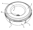
図1乃至図4中に示される実施例では、寛骨臼カップ人工器官設置器具は、固着(impaction)及び一時的試行挿入物として適合されるカップ1及びアダプタ2を有する。
In the embodiment shown in FIGS. 1-4, the acetabular cup prosthesis placement device has a
カップ1は、骨盤骨における寛骨臼窩へと固定されるよう意図される恒久的なカップを構成する。
The
他方では、アダプタ2は、カップ1とインパクタとの間の中間部分の機能を少なくとも有する。インパクタは、カップ1を寛骨臼窩において設置する際にカップ1を操作するよう使用される。アダプタ2は、続いて恒久的挿入物と置換されるよう意図される。
On the other hand, the
カップ1は、比較的薄い壁を有する半球形であり、図4においてより明らかに見られる通り一般的に半球形を有する凸状近位面3、任意で固定フィン4、及び凹状遠位面5を有する。該遠位面5は、周辺リップ6まで延在する円筒形又は僅かに円錐形の環状保持表面5bによって延在される半球形摺動表面5aを有する。
The
カップ1の半球形表面5aは、完全に平坦且つ一定であり、摺動表面を構成するよう、望ましくは鏡面磨きをされる。該表面において、カップ1が寛骨臼窩において適合された後にカップ1へと続いてもたらされる半球形の恒久的挿入物は、完全にピボットし得る。
The
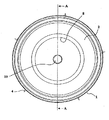
アダプタ2は、凸状近位面7及び半球形空洞8を有する遠位面11によって境界を定められる、全般的に円形を有する。
The
アダプタ2の凸状近位面7は、円筒形又は僅かに円錐形の環状係合表面7a、及びカップ1の半球形摺動表面5aを有する半球形から奥まって設置される中央ドーム7bを有する。この結果、図4中に示される強制的に適合された位置において、一時的挿入物2とカップ1との間に自由空間9が残る。
The convex proximal surface 7 of the
環状係合表面7aは、環状保持表面5bの形状に対応する形状、及び、カップ1の環状保持表面5bにおいて強制的に保持される直径を有する。そのため、アダプタ2及びカップ1は、互いに対する相対運動なく、高い機械的応力に耐え得るサブ組立体を構成することができる。該高い機械的応力は、カップが寛骨臼窩において設置される際に、カップに対して与えられなければならない力より大きい。
The
図5及び図6中、環状係合表面7a及び環状保持表面5bは、平坦である。
5 and 6, the
あるいは、図4の実施例において、カップ1の環状保持表面5bは、少なくとも1つの環状溝5cを有し、アダプタ2の環状係合表面7aは、環状溝5cにおいて係合されるよう適合された少なくとも1つの対応する環状リブ7cを有する。
Alternatively, in the embodiment of FIG. 4, the
アダプタ2の半球形空洞8は、大腿関節のオス部の球体関節頭部を受けるよう寸法決定される。それ故にアダプタ2は、一時的試行挿入物を構成し得る。
The
アクセスホール10は、アダプタ2の下部にあり、該ホールを介してアダプタ2とカップ1との間の自由空間9は外側と連絡する。
The
アダプタ2の遠位面11は、円形の周辺リブ12によって側面に位置される。該リブは、図4中に示される強制的に適合される位置においてカップ1の周辺リップ6上に位置する突き合わせ手段を構成する。この結果、周辺リブ12は、カップ1へのアダプタ2の更なる進入を妨げる。図中示される実施例では、アクセスホール10はまた、インパクタを取外し可能に固定する手段を構成する。この目的に対して、アクセスホールは雌ねじ10aを有する。
The
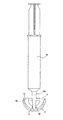
これより図5を参照する。該図は、カップ1,一時的試行挿入型のアダプタ2、アダプタ2の半球形空洞8、及びねじアクセスホール10を再度示す。
Reference is now made to FIG. The figure again shows the
この図はまた、ハンドル13a、ステム13b、及びアクセスホール10へとねじ込まれるねじ端部13cを有するインパクタ13を示す。インパクタ13は望ましくは、ねじ部13cの端部において、半球形部分13dを有する。該半球形部分は、アダプタ2の対応する半球形空洞8において収容されるよう適合及び寸法決定される。故に、インパクタ13は、寛骨臼窩への挿入及び位置付け中に、カップ1を操作するよう使用される。
This figure also shows an impactor 13 having a
図6は、カップ1からアダプタ2を分離する段階を示す。この実施例において、シリンジ14は、生理血清等である適切な液体を有して、並びにアダプタ2のアクセスホール10において流体気密に係合される端部14aを有して与えられる。シリンジ14は続いて、加圧下の液体を自由空間9へと注入するよう使用され、カップ1からアダプタ2を分離させる。
FIG. 6 shows the step of separating the
あるいは、補助的なシリンジの使用を避けるよう、インパクタ13は、管状ハンドルを有し得る。故に図5は、軸方向のパッセージ13eを有するインパクタ13を示す。分離段階中、液体は、軸方向パッセージ13eへ、続いて自由空間9へと液体をもたらすピストンロッド13fへともたらされ得る。
Alternatively, the impactor 13 can have a tubular handle to avoid the use of an auxiliary syringe. Thus, FIG. 5 shows an impactor 13 having an
図中示される実施例では、アダプタ2は、半球形空洞8を有し、一時的試行挿入物の機能を実行する。しかしながら、本発明の範囲から逸脱することなく、アダプタ2は、かかる半球形空洞を有さず、インパクタ13を用いて寛骨臼窩においてカップ1を位置付けるようアダプタとしての役割のみを果たす。
In the embodiment shown in the figure, the
同様に、図示される実施例では、アクセスホール10は、アダプタ2に対してインパクタ13を固定する手段として同時に働く。あるいは、ホールは、インパクタ13を固定するようアダプタ2の中心部分において与えられ得る。一方で、流体を注入するアクセスホール10は、動かされ得る。インパクタを固定するホールは、この場合、ブラインドホールでなければならない。
Similarly, in the illustrated embodiment, the
本発明に従った器具の使用は、以下において説明される。 The use of the instrument according to the invention is described below.
工場では、アダプタ2は、以下の段階を有する手順によってカップ1へと組み立てられ得る。
a) アダプタ2は、その寸法を僅かに低減するよう十分に低い温度まで冷却される。該寸法は、最初はアダプタ2の環状係合表面7aの直径が同一温度においてカップ1の環状保持表面5bの直径より僅かに大きいようにされる。アダプタ2の温度を低下することは、それ自体は室温のままにとどまるカップ1の入口との係合を促進するよう、アダプタの外径を低減させる。
b) 続いてアダプタ2は、周辺リブ12が周辺リップ6で終端となるよう、カップ1において位置付けられる。
c) カップにおいて配置され次第、アダプタ2は、それを拡大するよう室温まで戻ることを可能にされる。そのため、アダプタ2は、環状係合表面7aによってカップ1において流体気密であるよう強制的に適合及び強制的に保持される。
In the factory, the
a)
b) Subsequently, the
c) Once placed in the cup, the
アダプタ−カップ組立体は続いて、密封された保護エンベロープ15(図2参照)においてガンマ線によって殺菌される。この瞬間から先、アダプタ−カップ組立体は、密封保護エンベロープ15において殺菌状態にてパッケージされる。
The adapter-cup assembly is then sterilized by gamma radiation in a sealed protective envelope 15 (see FIG. 2). From this moment onwards, the adapter-cup assembly is packaged in a sterilized state in a sealed
使用の場所、即ち手術室において、執刀医は、密封保護エンベロープ15を取り除き、無菌のインパクタ13をアクセスホール10へとねじ込み得る。執刀医は続いて、インパクタ13及び強制的に適合されたアダプタ2を操作し得、カップ1に対して位置付け及び方向付けに必要である全ての機械的応力を与える。
At the point of use, i.e. the operating room, the surgeon can remove the sealed
執刀医は続いて、インパクタ13のねじを外して取り除く。 The surgeon then unscrews the impactor 13 and removes it.
執刀医は続いて、一時的試行挿入物としての役割を果たす、一時的挿入物型の球体関節頭部を、アダプタ2の半球形空洞8へと適合し得る。
The surgeon can subsequently fit a temporary insert-type spherical joint head that serves as a temporary trial insert into the
人工器官のオス部が選択され次第、執刀医は、図6中に示されるシリンジ14を用いて、あるいは、図5中に示すピストンロッド13f及び軸方向パッセージ13eを有するインパクタ13へと、加圧下の液体又は他の流体をもたらすことによって、一時的挿入物2をカップ1から取り外し得る。
As soon as the male part of the prosthesis is selected, the surgeon uses the
執刀医は続いて、寛骨臼窩において適所にあるカップ1へと恒久的挿入物を適合させる。
The surgeon then adapts the permanent insert to the
上述された全ての操作は、カップ1の半球形摺動表面8の変形の危険性を有さず、またカップ1上の所望されない力を有さず、実行される。
All the operations described above are carried out without the risk of deformation of the hemispherical sliding
本発明は、明記されてきた実施例に制限されず、また、添付の請求項の範囲内での変形及びその一般化を包含するものである。 The invention is not limited to the embodiments which have been specified, but also encompasses modifications and generalizations within the scope of the appended claims.
1 カップ
2 アダプタ
3 凹状近位面
4 固定フィン
5 凹状遠位面
5a 半球形摺動表面
5b 環状保持表面
5c 環状溝
6 周辺リップ
7 凸状近位面
7a 環状係合表面
7b 中央ドーム
7c 環状リブ
8 半球形空洞
9 自由空間
10 アクセスホール
10a 雌ねじ
11 遠位面
12 周辺リブ
13 インパクタ
13a ハンドル
13b ステム
13c ねじ端部
13d 半球形部分
13e パッセージ
13f ピストンロッド
14 シリンジ
14a 端部
15 保護エンベロープ
1
Claims (15)
前記セットは、
− カップと、
− インパクタと、
− 前記カップを前記インパクタに締結するアダプタとを含み、
前記カップは、その外側表面である凸状近位面と、その内側表面である凹状遠位面と、周辺リップとによって境界を定められ、
− 前記カップは、前記アダプタを前記カップに取り外し可能に固定し、前記アダプタが前記カップに固定されるや否や、前記アダプタと前記カップの前記内側表面との間に自由空間を残す、第一固定手段を含み、
− 前記アダプタは、前記アダプタを前記インパクタに取り外し可能に固定する第二固定手段を含み、
− 前記アダプタは、アクセスホールを含み、前記自由空間は、流体を圧力下で前記アクセスホールを通じて前記自由空間内に注入し得るよう、前記アクセスホールを通じて外側と連絡し、
− 前記カップ上の前記第一固定手段は、前記凹状遠位面を前記周辺リップに向かって延在させる円筒形又は円錐形の環状保持表面を含み、
− 前記アダプタ上の前記第二固定手段は、円筒形又は円錐形の環状係合表面を含み、
− 前記環状保持表面及び前記環状係合表面は、同一の形状を有し、
当該方法は、
a) 前記アダプタの寸法を低減するよう前記アダプタを冷却するステップと、
b) 前記アダプタを前記カップ内に位置付けるステップと、
c) 前記アダプタが前記カップ内に配置されるや否や、前記アダプタの前記環状係合表面が前記カップの前記環状保持表面内に流体密な方法で強制的に固定されるよう、前記アダプタが室温に戻り、膨張することを可能にするステップとを含む、
方法。 A method of assembling a set of installation means for an acetabular cup prosthesis,
The set is
- a mosquito-up,
- and the impactor,
- and a adapter for fastening the cup to the impactor,
The cup is bounded by a convex proximal surface that is an outer surface thereof, a concave distal surface that is an inner surface thereof, and a peripheral lip;
- the cup, the adapter can be fixed removably to the cup, leaving a free space between the adapter as soon as secured to the cup, the inner surface of the said adapter cup, first fixing Including means,
- said adapter includes a second fixing means for releasably securing said adapter to said impactor,
The adapter includes an access hole, the free space communicating with the outside through the access hole so that fluid can be injected into the free space through the access hole under pressure;
- the first fixing means on said cup includes a cylindrical or annular holding surface of the conical extend toward the concave distal surface to the peripheral lip,
- the second fastening means on said adapter includes an annular engaging surface of the cylindrical or conical,
- said annular retaining surface and the annular engagement surface has the same shape,
The method is
a) cooling the adapter to reduce the size of the adapter;
b) positioning the adapter in the cup;
c) As soon as the adapter is placed in the cup, the adapter is at room temperature so that the annular engagement surface of the adapter is forcibly fixed in a fluid-tight manner in the annular holding surface of the cup. Returning to and allowing to expand,
Method.
Applications Claiming Priority (2)
| Application Number | Priority Date | Filing Date | Title |
|---|---|---|---|
| FR0410879A FR2876278B1 (en) | 2004-10-13 | 2004-10-13 | COTYL APPLICATION INSTRUMENTS |
| FR0410879 | 2004-10-13 |
Related Parent Applications (1)
| Application Number | Title | Priority Date | Filing Date |
|---|---|---|---|
| JP2007536222A Division JP2008515579A (en) | 2004-10-13 | 2005-10-13 | Instruments for installing acetabular cups |
Publications (3)
| Publication Number | Publication Date |
|---|---|
| JP2012120870A true JP2012120870A (en) | 2012-06-28 |
| JP2012120870A5 JP2012120870A5 (en) | 2012-08-09 |
| JP5367104B2 JP5367104B2 (en) | 2013-12-11 |
Family
ID=34952812
Family Applications (2)
| Application Number | Title | Priority Date | Filing Date |
|---|---|---|---|
| JP2007536222A Pending JP2008515579A (en) | 2004-10-13 | 2005-10-13 | Instruments for installing acetabular cups |
| JP2012035576A Active JP5367104B2 (en) | 2004-10-13 | 2012-02-21 | Instruments for installing acetabular cups |
Family Applications Before (1)
| Application Number | Title | Priority Date | Filing Date |
|---|---|---|---|
| JP2007536222A Pending JP2008515579A (en) | 2004-10-13 | 2005-10-13 | Instruments for installing acetabular cups |
Country Status (7)
| Country | Link |
|---|---|
| US (3) | US9814603B2 (en) |
| EP (1) | EP1811928B1 (en) |
| JP (2) | JP2008515579A (en) |
| CN (1) | CN101039638B (en) |
| ES (1) | ES2388143T3 (en) |
| FR (1) | FR2876278B1 (en) |
| WO (1) | WO2006040483A1 (en) |
Cited By (2)
| Publication number | Priority date | Publication date | Assignee | Title |
|---|---|---|---|---|
| JP2016522058A (en) * | 2013-06-19 | 2016-07-28 | アースレックス インコーポレイテッドArthrex, Inc. | Stemless shoulder implant |
| JP2021035534A (en) * | 2015-07-27 | 2021-03-04 | ヒップ イノベーション テクノロジー、エルエルシー | Impactor for implantation of artificial hip joint |
Families Citing this family (38)
| Publication number | Priority date | Publication date | Assignee | Title |
|---|---|---|---|---|
| US8806973B2 (en) | 2009-12-02 | 2014-08-19 | Covidien Lp | Adapters for use between surgical handle assembly and surgical end effector |
| US20090088846A1 (en) | 2007-04-17 | 2009-04-02 | David Myung | Hydrogel arthroplasty device |
| US8277457B1 (en) | 2004-12-09 | 2012-10-02 | Greatbatch Medical S.A. | Orthopaedic inserter using a collet mechanism |
| US7621921B2 (en) * | 2006-01-25 | 2009-11-24 | Symmetry Medical, Inc | Split thread orthopaedic implant impactor |
| DE102007020484A1 (en) * | 2006-05-01 | 2007-12-13 | Precimed S.A. | Insertion instrument for minimally invasive joint surgery with exchangeable thread |
| DE202006010069U1 (en) * | 2006-06-28 | 2007-11-08 | Waldemar Link Gmbh & Co. Kg | Insertion device for joint sockets of prostheses |
| FR2911062B1 (en) * | 2007-01-08 | 2009-07-03 | Thomas Gradel | COTYL WITH STERILE INTERFACE |
| US8517241B2 (en) | 2010-04-16 | 2013-08-27 | Covidien Lp | Hand-held surgical devices |
| FR2921821B1 (en) * | 2007-10-09 | 2011-03-18 | Rech S Et De Fabrication Serf Soc Et | ANCILLARY FOR DETERMINING THE DIMENSIONS AND POSITIONING OF A COTYLOID IMPLANT OF A HIP PROSTHESIS |
| US20120209396A1 (en) | 2008-07-07 | 2012-08-16 | David Myung | Orthopedic implants having gradient polymer alloys |
| KR20110040969A (en) | 2008-08-05 | 2011-04-20 | 바이오미메디카, 인코포레이티드 | Polyurethane-grafted hydrogels |
| GB0819380D0 (en) * | 2008-10-23 | 2008-11-26 | Depuy Int Ltd | A surgical instrument |
| US8398650B1 (en) | 2009-01-27 | 2013-03-19 | Greatbatch Medical S.A. | Offset cup impactor with an expandable dome for double mobility implants |
| US10420648B2 (en) * | 2009-06-10 | 2019-09-24 | Jean-Pierre LAFFAY | Acetabular prosthetic system with simplified impaction |
| FR2950525B1 (en) | 2009-09-28 | 2013-05-10 | Thomas Gradel | HIP PROTHETIC COTYL WITH EXTERNAL FASTENING |
| FR2951071B1 (en) * | 2009-10-12 | 2011-10-28 | Thomas Gradel | PROTHETIC COTYLE WITH LARGE RETENTION CAPACITY |
| EP2512354A4 (en) * | 2009-12-18 | 2015-09-09 | Biomimedica Inc | Method, device, and system for shaving and shaping of a joint |
| FR2961387B1 (en) * | 2010-06-17 | 2013-06-07 | Thomas Gradel | CERAMIC COTYL WITH EXTERNAL FASTENING |
| CA2808528A1 (en) | 2010-08-27 | 2012-03-01 | Biomimedica, Inc. | Hydrophobic and hydrophilic interpenetrating polymer networks derived from hydrophobic polymers and methods of preparing the same |
| US8961528B2 (en) * | 2010-08-27 | 2015-02-24 | Greatbatch Medical S.A. | Offset cup impactor with a grasping plate for double mobility implants |
| CH703945A1 (en) * | 2010-10-07 | 2012-04-13 | Jossi Holding Ag | Acetabular cup and method for making a joint socket. |
| US9119731B2 (en) | 2011-01-17 | 2015-09-01 | Greatbach Medical S.A. | Straight cup impactor |
| US8585709B2 (en) | 2011-01-17 | 2013-11-19 | Greatbatch Medical S.A. | Straight cup impactor with lever arm |
| WO2012151393A2 (en) * | 2011-05-03 | 2012-11-08 | Smith & Nephew, Inc. | Patient-matched guides for orthopedic implants |
| EP2561835B1 (en) * | 2011-08-26 | 2016-03-16 | Greatbatch Medical SA | Straight cup impactor |
| US9028502B2 (en) * | 2011-09-23 | 2015-05-12 | Greatbatch Medical S.A. | Ceramic implant holder |
| CA2885996A1 (en) | 2011-10-03 | 2013-04-11 | Biomimedica, Inc. | Polymeric adhesive for anchoring compliant materials to another surface |
| US9114024B2 (en) | 2011-11-21 | 2015-08-25 | Biomimedica, Inc. | Systems, devices, and methods for anchoring orthopaedic implants to bone |
| US20140309749A1 (en) * | 2011-11-23 | 2014-10-16 | Depuy (Ireland) | Surgical instrument head and assembly including tab separation member |
| CN102908214B (en) * | 2012-09-21 | 2015-01-28 | 联合骨科器材股份有限公司 | Acetabular cup implanter |
| US11077228B2 (en) | 2015-08-10 | 2021-08-03 | Hyalex Orthopaedics, Inc. | Interpenetrating polymer networks |
| GB2552173A (en) * | 2016-07-12 | 2018-01-17 | Susannah Germaine Clarke | Holder for acetabular cup implant |
| FR3066908B1 (en) * | 2017-05-31 | 2019-07-19 | Science Et Medecine | ORTHOPEDIC ASSEMBLY COMPRISING A CUPULE AND AN APPARATUS FOR THE PLACEMENT OF THIS CUP IN AN ANATOMIC CAVITY |
| US10869950B2 (en) | 2018-07-17 | 2020-12-22 | Hyalex Orthopaedics, Inc. | Ionic polymer compositions |
| US11103367B2 (en) | 2019-02-15 | 2021-08-31 | Encore Medical, L.P. | Acetabular liner |
| CN111150481A (en) * | 2020-01-17 | 2020-05-15 | 北京市春立正达医疗器械股份有限公司 | Acetabulum outer cup installer |
| FR3117771B1 (en) * | 2020-12-23 | 2023-02-24 | Soc Detudes De Recherches Et De Fabrication Serf | Device for engaging a spherical head in an insert |
| FR3134309A1 (en) * | 2022-04-08 | 2023-10-13 | Fx Solutions | Implant mainly made of ceramic and assembly with gripping and placement device |
Citations (9)
| Publication number | Priority date | Publication date | Assignee | Title |
|---|---|---|---|---|
| JPS62502241A (en) * | 1985-03-21 | 1987-09-03 | ミネソタ マイニング アンド マニユフアクチユアリング コンパニ− | Acetabular cup positioning device |
| US5061270A (en) * | 1991-03-18 | 1991-10-29 | Aboczky Robert I | System for orienting, inserting and impacting an acetabular cup prosthesis |
| US5169399A (en) * | 1991-10-17 | 1992-12-08 | Boehringer Mannheim Corporation | Acetabular cup impactor |
| US5571200A (en) * | 1994-08-04 | 1996-11-05 | Implex Corporation | Acetabular cup, method and tool for installing the same |
| JPH08510945A (en) * | 1993-10-29 | 1996-11-19 | ハウメディカ・インコーポレーテッド | Acetabular cup positioning tool and acetabular cup positioning method |
| DE19628193A1 (en) * | 1996-07-12 | 1998-01-22 | Eska Implants Gmbh & Co | Insertion instrument for acetabular cup prosthesis |
| FR2785523A1 (en) * | 1998-11-10 | 2000-05-12 | Serf Sa | Metal socket for replacement hip joint has elongated hemi-spherical inner surface with cylindrical extension forming entry opening |
| US6152930A (en) * | 1998-10-28 | 2000-11-28 | Depuy Orthopaedics, Inc. | Acetabular cup extraction system |
| FR2809305A1 (en) * | 2000-05-26 | 2001-11-30 | Amplitude | ANCILLARY INSTRUMENT FOR THE INSTALLATION OF A COTYLOID CUP FOR HIP JOINT PROSTHESIS |
Family Cites Families (15)
| Publication number | Priority date | Publication date | Assignee | Title |
|---|---|---|---|---|
| US5320625A (en) * | 1993-01-21 | 1994-06-14 | Bertin Kim C | Apparatus and method for implanting a prosthetic acetabular cup and then testing the stability of the implant |
| US6048269A (en) * | 1993-01-22 | 2000-04-11 | Mgm Grand, Inc. | Coinless slot machine system and method |
| US5474560A (en) * | 1994-09-26 | 1995-12-12 | Zimmer, Inc. | Prosthetic acetabular cup inserter |
| DE29608453U1 (en) * | 1996-05-09 | 1997-09-11 | Link Waldemar Gmbh Co | Hip cup and surgical instrument for inserting the same |
| GB9623942D0 (en) * | 1996-11-15 | 1997-01-08 | Johnson & Johnson Professional | Extraction device |
| EP0888759B1 (en) * | 1997-07-04 | 2003-01-02 | Sulzer Orthopädie AG | Instrument for introduction of an insert of an implant into the associated shell |
| US5904688A (en) * | 1997-12-30 | 1999-05-18 | Bristol-Myers Squibb Co. | Orthopaedic assembly including an acetabular cup and cup inserter |
| WO1999056677A1 (en) * | 1998-04-30 | 1999-11-11 | Ceramtec Ag | Instrument for manipulating components of joint prostheses |
| AU783205C (en) * | 2000-03-15 | 2006-08-17 | Depuy Orthopaedics, Inc. | Prosthetic cup assembly which includes components possessing self-locking taper |
| US7597715B2 (en) * | 2005-04-21 | 2009-10-06 | Biomet Manufacturing Corp. | Method and apparatus for use of porous implants |
| US20030229357A1 (en) * | 2002-06-10 | 2003-12-11 | Donald Dye | Femoral head holder and impaction instrument and method of use |
| US6875237B2 (en) * | 2003-02-27 | 2005-04-05 | Zimmer Austin, Inc. | Driving instrument with variably angled joint and extended tip and method of use for minimally invasive hip surgery |
| US20050149047A1 (en) * | 2004-01-05 | 2005-07-07 | Paramount Medical Instruments, L.L.C. | Method of attaching an implant to an impactor |
| US7744602B2 (en) * | 2005-01-28 | 2010-06-29 | Steven M. Teeny | Acetabular shell removal tool |
| GB2423715A (en) * | 2005-03-01 | 2006-09-06 | Corin Ltd | Surgical introducer |
-
2004
- 2004-10-13 FR FR0410879A patent/FR2876278B1/en active Active
-
2005
- 2005-10-13 US US11/576,894 patent/US9814603B2/en active Active
- 2005-10-13 EP EP05809187A patent/EP1811928B1/en active Active
- 2005-10-13 JP JP2007536222A patent/JP2008515579A/en active Pending
- 2005-10-13 CN CN2005800346530A patent/CN101039638B/en active Active
- 2005-10-13 WO PCT/FR2005/002542 patent/WO2006040483A1/en active Application Filing
- 2005-10-13 ES ES05809187T patent/ES2388143T3/en active Active
-
2012
- 2012-02-21 JP JP2012035576A patent/JP5367104B2/en active Active
-
2016
- 2016-01-28 US US15/008,655 patent/US9474628B2/en active Active
-
2017
- 2017-10-04 US US15/724,327 patent/US10398570B2/en active Active
Patent Citations (9)
| Publication number | Priority date | Publication date | Assignee | Title |
|---|---|---|---|---|
| JPS62502241A (en) * | 1985-03-21 | 1987-09-03 | ミネソタ マイニング アンド マニユフアクチユアリング コンパニ− | Acetabular cup positioning device |
| US5061270A (en) * | 1991-03-18 | 1991-10-29 | Aboczky Robert I | System for orienting, inserting and impacting an acetabular cup prosthesis |
| US5169399A (en) * | 1991-10-17 | 1992-12-08 | Boehringer Mannheim Corporation | Acetabular cup impactor |
| JPH08510945A (en) * | 1993-10-29 | 1996-11-19 | ハウメディカ・インコーポレーテッド | Acetabular cup positioning tool and acetabular cup positioning method |
| US5571200A (en) * | 1994-08-04 | 1996-11-05 | Implex Corporation | Acetabular cup, method and tool for installing the same |
| DE19628193A1 (en) * | 1996-07-12 | 1998-01-22 | Eska Implants Gmbh & Co | Insertion instrument for acetabular cup prosthesis |
| US6152930A (en) * | 1998-10-28 | 2000-11-28 | Depuy Orthopaedics, Inc. | Acetabular cup extraction system |
| FR2785523A1 (en) * | 1998-11-10 | 2000-05-12 | Serf Sa | Metal socket for replacement hip joint has elongated hemi-spherical inner surface with cylindrical extension forming entry opening |
| FR2809305A1 (en) * | 2000-05-26 | 2001-11-30 | Amplitude | ANCILLARY INSTRUMENT FOR THE INSTALLATION OF A COTYLOID CUP FOR HIP JOINT PROSTHESIS |
Cited By (5)
| Publication number | Priority date | Publication date | Assignee | Title |
|---|---|---|---|---|
| JP2016522058A (en) * | 2013-06-19 | 2016-07-28 | アースレックス インコーポレイテッドArthrex, Inc. | Stemless shoulder implant |
| JP2021035534A (en) * | 2015-07-27 | 2021-03-04 | ヒップ イノベーション テクノロジー、エルエルシー | Impactor for implantation of artificial hip joint |
| JP2021035535A (en) * | 2015-07-27 | 2021-03-04 | ヒップ イノベーション テクノロジー、エルエルシー | Impactor for implantation of artificial hip joint |
| JP7018220B2 (en) | 2015-07-27 | 2022-02-10 | ヒップ イノベーション テクノロジー、エルエルシー | Impactor for hip prosthesis transplantation |
| JP7018219B2 (en) | 2015-07-27 | 2022-02-10 | ヒップ イノベーション テクノロジー、エルエルシー | Impactor for hip prosthesis transplantation |
Also Published As
| Publication number | Publication date |
|---|---|
| FR2876278A1 (en) | 2006-04-14 |
| ES2388143T3 (en) | 2012-10-09 |
| EP1811928A1 (en) | 2007-08-01 |
| US9474628B2 (en) | 2016-10-25 |
| US20180055656A1 (en) | 2018-03-01 |
| US9814603B2 (en) | 2017-11-14 |
| JP2008515579A (en) | 2008-05-15 |
| CN101039638B (en) | 2012-02-29 |
| US20080077249A1 (en) | 2008-03-27 |
| JP5367104B2 (en) | 2013-12-11 |
| FR2876278B1 (en) | 2007-10-26 |
| WO2006040483A1 (en) | 2006-04-20 |
| US20160135965A1 (en) | 2016-05-19 |
| US10398570B2 (en) | 2019-09-03 |
| EP1811928B1 (en) | 2012-05-16 |
| CN101039638A (en) | 2007-09-19 |
Similar Documents
| Publication | Publication Date | Title |
|---|---|---|
| JP5367104B2 (en) | Instruments for installing acetabular cups | |
| JP5671106B2 (en) | Method for manufacturing an artificial acetabular external assembly | |
| EP2638881B1 (en) | Joint implant trial components | |
| EP1293179A1 (en) | Resilient thimble for ball head of prosthetic joint | |
| US9987139B2 (en) | Method for manufacturing a prosthetic hip acetabulum | |
| EP0611558B1 (en) | Dual fixation prosthesis | |
| US9402742B2 (en) | Medical device and method | |
| US9173740B2 (en) | Method for producing a ceramic acetabulum |
Legal Events
| Date | Code | Title | Description |
|---|---|---|---|
| A521 | Request for written amendment filed |
Free format text: JAPANESE INTERMEDIATE CODE: A523 Effective date: 20120613 |
|
| A131 | Notification of reasons for refusal |
Free format text: JAPANESE INTERMEDIATE CODE: A131 Effective date: 20130430 |
|
| A521 | Request for written amendment filed |
Free format text: JAPANESE INTERMEDIATE CODE: A523 Effective date: 20130710 |
|
| TRDD | Decision of grant or rejection written | ||
| A01 | Written decision to grant a patent or to grant a registration (utility model) |
Free format text: JAPANESE INTERMEDIATE CODE: A01 Effective date: 20130813 |
|
| A61 | First payment of annual fees (during grant procedure) |
Free format text: JAPANESE INTERMEDIATE CODE: A61 Effective date: 20130910 |
|
| R150 | Certificate of patent or registration of utility model |
Ref document number: 5367104 Country of ref document: JP Free format text: JAPANESE INTERMEDIATE CODE: R150 Free format text: JAPANESE INTERMEDIATE CODE: R150 |
|
| R250 | Receipt of annual fees |
Free format text: JAPANESE INTERMEDIATE CODE: R250 |
|
| R250 | Receipt of annual fees |
Free format text: JAPANESE INTERMEDIATE CODE: R250 |
|
| R250 | Receipt of annual fees |
Free format text: JAPANESE INTERMEDIATE CODE: R250 |
|
| R250 | Receipt of annual fees |
Free format text: JAPANESE INTERMEDIATE CODE: R250 |
|
| R250 | Receipt of annual fees |
Free format text: JAPANESE INTERMEDIATE CODE: R250 |
|
| R250 | Receipt of annual fees |
Free format text: JAPANESE INTERMEDIATE CODE: R250 |
|
| R250 | Receipt of annual fees |
Free format text: JAPANESE INTERMEDIATE CODE: R250 |
|
| R250 | Receipt of annual fees |
Free format text: JAPANESE INTERMEDIATE CODE: R250 |