JP2012118637A - Authentication system, input device, and authentication program - Google Patents
Authentication system, input device, and authentication program Download PDFInfo
- Publication number
- JP2012118637A JP2012118637A JP2010265778A JP2010265778A JP2012118637A JP 2012118637 A JP2012118637 A JP 2012118637A JP 2010265778 A JP2010265778 A JP 2010265778A JP 2010265778 A JP2010265778 A JP 2010265778A JP 2012118637 A JP2012118637 A JP 2012118637A
- Authority
- JP
- Japan
- Prior art keywords
- touch panel
- identification information
- authentication
- conductive contact
- input device
- Prior art date
- Legal status (The legal status is an assumption and is not a legal conclusion. Google has not performed a legal analysis and makes no representation as to the accuracy of the status listed.)
- Pending
Links
Images


Landscapes
- Position Input By Displaying (AREA)
Abstract
Description
本発明は、認証システム、特に、静電容量方式のタッチパネル装置を用いた認証システムに関する。 The present invention relates to an authentication system, and more particularly to an authentication system using a capacitive touch panel device.
タッチパネルには、抵抗膜方式、赤外線方式、静電容量方式、超音波方式といった複数の方式がある。静電容量方式は、静電容量の変化を利用して位置検出を行う方式である。静電容量方式は、表面型と投影型の2種類に分かれる。表面型は1シート状の透明電極を用いたアナログ検出方法であり、投影型はX−Yの格子状の駆動電極を用いた積算検出方法である。 There are a plurality of touch panel methods such as a resistive film method, an infrared method, a capacitance method, and an ultrasonic method. The electrostatic capacity method is a method of performing position detection using a change in electrostatic capacity. There are two types of capacitance methods: surface type and projection type. The surface type is an analog detection method using a single sheet-like transparent electrode, and the projection type is an integration detection method using XY grid-like drive electrodes.
このようなタッチパネルは、例えばタブレット型コンピュータに採用される等して、普及が進んでいる。そして、従来の紙ベースで行う作業も、タッチパネルが搭載されたタブレット型コンピュータで行われることが望まれているケースがある。例えば、文書情報に対して捺印を行う作業をタブレット型コンピュータのタッチパネルで実行するための電子捺印装置が知られている(例えば、特許文献1を参照。)。 Such touch panels have been widely used, for example, by being adopted in tablet computers. In addition, there are cases where it is desired that the conventional paper-based work is also performed by a tablet computer equipped with a touch panel. For example, there is known an electronic stamping apparatus for executing a stamping operation on document information with a touch panel of a tablet computer (see, for example, Patent Document 1).
一般に静電容量方式のタッチパネルは、操作者が指を使って入力を行うことを想定している。したがって、指以外の手段によって特定の情報を入力することについては、従来では具体的な解決方法が検討されてこなかった。そのため、電子捺印装置を静電容量方式のタッチパネルで実現する場合に、簡単な構造及び操作で識別情報を入力可能とすることが実現されていなかった。 In general, it is assumed that a capacitive touch panel is input by an operator using a finger. Therefore, no specific solution has been studied in the past for inputting specific information by means other than a finger. For this reason, when the electronic stamping apparatus is realized by a capacitive touch panel, it has not been realized that identification information can be input with a simple structure and operation.
本発明の課題は、静電容量方式のタッチパネル装置において、簡単な構造及び操作によって認証を可能にすることにある。 An object of the present invention is to enable authentication with a simple structure and operation in a capacitive touch panel device.
以下に、課題を解決するための手段として複数の態様を説明する。これら態様は、必要に応じて任意に組み合わせることができる。 Hereinafter, a plurality of modes will be described as means for solving the problems. These aspects can be arbitrarily combined as necessary.
本発明の一見地に係る認証システムは、静電容量方式のタッチパネル装置と、入力装置とを備えている。入力装置は、タッチパネル装置に対して、静電容量の変化からなる識別情報を入力可能である。タッチパネル装置は、入力された識別情報に対して認証を行う。 An authentication system according to an aspect of the present invention includes a capacitive touch panel device and an input device. The input device can input identification information including a change in capacitance to the touch panel device. The touch panel device authenticates the input identification information.
このシステムでは、入力装置が静電容量の変化からなる識別情報をタッチパネル装置に対して入力すれば、タッチパネル装置が入力された識別情報に対して認証を行う。このように簡単な構造及び操作によって、静電容量方式のタッチパネル装置を用いた認証が可能になっている。 In this system, when the input device inputs identification information including a change in capacitance to the touch panel device, the touch panel device authenticates the input identification information. Such simple structure and operation enable authentication using a capacitive touch panel device.
タッチパネル装置は、入力装置からの識別情報を認証した後に、入力装置ごとに異なる動作を実行してもよい。 The touch panel device may perform different operations for each input device after authenticating the identification information from the input device.
このシステムでは、操作者は、自分が用いた入力装置による認証が正しく行われた場合に、タッチパネル装置の動作に基づいてそのことを知ることができる。 In this system, the operator can know the fact based on the operation of the touch panel device when the authentication by the input device used by the operator is correctly performed.
タッチパネル装置は、入力装置からの識別情報を認証した後に、入力装置を特定する情報を表示してもよい。 The touch panel device may display information identifying the input device after authenticating the identification information from the input device.
このシステムでは、例えば、判子を紙に押したときに印鑑画像が映るように、入力装置を特定する情報がタッチパネル装置の表面に表示される。これにより、操作者は、自分が用いた入力装置による認証が正しく行われた場合に、タッチパネル装置の動作に基づいてそのことを知ることができる。 In this system, for example, information specifying the input device is displayed on the surface of the touch panel device so that a seal image is displayed when the stamp is pushed onto the paper. As a result, the operator can know the fact based on the operation of the touch panel device when the authentication by the input device used by the operator is correctly performed.
タッチパネル装置は、静電容量方式のタッチパネルと、記憶部と、表示部とを備えていてもよい。記憶部は、タッチパネルが検出した識別情報を記憶する。表示部は、記憶部に記憶された識別情報に基づいて、入力装置に対応する画像を表示する。 The touch panel device may include a capacitive touch panel, a storage unit, and a display unit. The storage unit stores identification information detected by the touch panel. The display unit displays an image corresponding to the input device based on the identification information stored in the storage unit.
このシステムでは、記憶部に記憶された識別情報に基づいて、入力装置に対応する画像が表示される。これにより、操作者は、自分が用いた入力装置による認証が正しく行われた場合に、タッチパネル装置の表示に基づいてそのことを知ることができる。 In this system, an image corresponding to the input device is displayed based on the identification information stored in the storage unit. As a result, the operator can know the fact based on the display of the touch panel device when the authentication by the input device used by the operator is correctly performed.
入力装置は、第1導電性接触部と、第2導電性接触部と、断続器と、制御部とを有していてもよい。第1導電性接触部は、タッチパネル装置の表面に接触する。第2導電性接触部は、人間の指が接触可能である。断続器は、第1導電性接触部と第2導電性接触部との間に設けられている。制御部は、断続器を所定のパターンで断続動作させる。 The input device may include a first conductive contact part, a second conductive contact part, an interrupter, and a control part. The first conductive contact portion contacts the surface of the touch panel device. The second conductive contact portion can be touched by a human finger. The interrupter is provided between the first conductive contact portion and the second conductive contact portion. The control unit intermittently operates the interrupter in a predetermined pattern.
このシステムでは、制御部が断続器を所定のパターンで断続動作させると、第1導電性接触部と第2導電性接触部は連通と切断を繰り返す。これにより、所定のパターンの静電容量の変化からなる識別情報が、タッチパネル装置によって検出される。 In this system, when the control unit intermittently operates the interrupter in a predetermined pattern, the first conductive contact unit and the second conductive contact unit repeat communication and disconnection. Thereby, the identification information which consists of the change of the electrostatic capacitance of a predetermined pattern is detected by the touch panel device.
第1導電性接触部は、弾性変形可能な部材を有していてもよい。 The first conductive contact portion may have an elastically deformable member.
このシステムでは、第1導電性接触部が全体的にタッチパネル装置の表面に接触するので、識別情報が安定的にタッチパネル装置に入力される。 In this system, since the first conductive contact portion entirely contacts the surface of the touch panel device, the identification information is stably input to the touch panel device.
断続器は、第1導電性接触部がタッチパネル装置の表面からの反力によって押されることで制御部を動作状態にするスイッチをさらに有していてもよい。 The interrupter may further include a switch that causes the control unit to be in an operating state when the first conductive contact unit is pressed by a reaction force from the surface of the touch panel device.
このシステムでは、操作者が入力装置をタッチパネル装置の表面に押し付けることで、スイッチが制御部を動作状態にして、その結果、入力装置からタッチパネル装置に識別情報が入力される。つまり、操作者が入力装置をタッチパネル装置に押し付けた状態を維持することで、入力装置とタッチパネル装置の通信が安定的に行われる。 In this system, when the operator presses the input device against the surface of the touch panel device, the switch causes the control unit to be in an operating state, and as a result, identification information is input from the input device to the touch panel device. That is, the communication between the input device and the touch panel device is stably performed by maintaining the state where the operator presses the input device against the touch panel device.
入力装置は、断続器を収容しており、先端に第1導電性接触部が露出した状態で配置され、操作者の指が接触する位置に第2導電性接触部が露出した状態で配置される筐体をさらに有していてもよい。 The input device accommodates the interrupter, is arranged with the first conductive contact portion exposed at the tip, and is arranged with the second conductive contact portion exposed at a position where the operator's finger contacts. It may further have a housing.
このシステムでは、操作者が筐体を持つときに指が第2導電性接触部に接触するので、操作者は、第2導電性接触部に触れることをあまり意識することなく、入力装置を用いて識別情報をタッチパネル装置に入力できる。 In this system, since the finger contacts the second conductive contact portion when the operator holds the casing, the operator uses the input device without being conscious of touching the second conductive contact portion. Identification information can be input to the touch panel device.
本発明の他の見地に係る入力装置は、静電容量方式のタッチパネル装置に対して、静電容量の変化からなる識別情報を入力可能な入力装置である。入力装置は、第1導電性接触部と、第2導電性接触部と、断続器と、制御部とを有している。第1導電性接触部は、タッチパネル装置の表面に接触する。第2導電性接触部は、人間の指が接触可能である断続器は、第1導電性接触部と第2導電性接触部との間に設けられている。制御部は、断続器を所定のパターンで断続動作させる。 An input device according to another aspect of the present invention is an input device capable of inputting identification information including a change in capacitance to a capacitive touch panel device. The input device includes a first conductive contact portion, a second conductive contact portion, an interrupter, and a control unit. The first conductive contact portion contacts the surface of the touch panel device. The second conductive contact portion is provided between the first conductive contact portion and the second conductive contact portion, and the interrupter capable of being touched by a human finger is provided. The control unit intermittently operates the interrupter in a predetermined pattern.
本発明のさらに他の見地に係る認証プログラムは、静電容量方式のタッチパネル装置において、静電容量の変化からなる識別情報を認証するものであり、以下のステップを含む方法をコンピュータに実行させる。 An authentication program according to still another aspect of the present invention authenticates identification information including a change in capacitance in a capacitive touch panel device, and causes a computer to execute a method including the following steps.
◎識別情報が入力されたときに識別情報を検出するステップ
◎識別情報からタッチダウン又はタッチアップの時間間隔を計測するステップ
◎計測結果を認証データと照合するステップ
◎照合結果を報知するステップ
◎ Step of detecting the identification information when the identification information is inputted ◎ Step of measuring the touchdown or touch-up time interval from the identification information ◎ Step of comparing the measurement result with the authentication data ◎ Step of informing the verification result
本発明に係る認証システムでは、静電容量方式のタッチパネル装置において、簡単な操作によって認証が可能になる。 In the authentication system according to the present invention, authentication can be performed by a simple operation in a capacitive touch panel device.
(1)認証システムの基本構成
図1を用いて、本発明の一実施形態としての認証システム1を説明する。図1は、認証システムの概略構成を示すブロック図である。
(1) Basic Configuration of Authentication System An
認証システム1は、タブレット型コンピュータ3と、電子印鑑5とを備えている。電子印鑑5は、タブレット型コンピュータ3に対して、静電容量の変化からなる識別情報を入力可能な認証器である。タブレット型コンピュータ3は、入力された識別情報に対して認証を行う。
The
(2)タブレット型コンピュータ
タブレット型コンピュータ3は、主に、タッチパネル7と、ディスプレイ9と、制御部11とを有している。タッチパネル7は、静電容量方式のタッチパネルである。ディスプレイ9は、例えば、液晶ディスプレイである。
(2) Tablet Computer The
制御部11は、タッチパネル7に信号が入力されると、それに基づいて情報処理を行い、さらにディスプレイ9に各種表示を行わせる。制御部11は、CPU、RAM、ROM等からなりプログラムを実行するコンピュータであり、認証部13、表示制御部15、入力データ記憶部17、認証データ記憶部19、タイマー部21、及び表示データ記憶部23を有している。入力データ記憶部17には、電子印鑑5から入力された識別情報が保存される。認証データ記憶部19には、認証部13が認証を行う認証データが予め保存されている。認証データとは、識別情報に対応するデータである。タイマー部21は、必要に応じて生成され、タッチダウン及びタッチアップの時間間隔を計測する。表示データ記憶部23には、認証データに対応する表示データと、承認不可を示す表示データとが予め保存されている。認証データに対応する表示データとは、この実施形態では、印鑑画像である。
When a signal is input to the
認証部13は、タッチパネル7が検出した識別情報を入力データ記憶部17に記憶させ、続いて、入力データ記憶部17に記憶された入力データを認証データ記憶部19に記憶された認証データと照合する。認証部13は、入力データに対応する認証データがある場合は表示制御部15にその旨を通知し、入力データに対応する認証データがない場合は表示制御部15にその旨を通知する。なお、認証部13は、電子印鑑5の押捺位置すなわち座標位置を検出する機能も有している。
The
表示制御部15は、認証部13からの指示に従って、表示データ記憶部23に記憶された表示データをディスプレイ9に表示する。
The
(3)電子印鑑
図2〜図6を用いて、電子印鑑5の構造及び動作を説明する。図2は電子印鑑の斜視図であり、図3は電子印鑑の分解斜視図であり、図4は電子印鑑の概略断面図であり、図5及び図6はスイッチングリレーの動作原理を示す模式図である。
(3) Electronic seal stamp The structure and operation | movement of the
電子印鑑5は、タッチパネル7に対して人間の指の延長として機能する導電部材であり、さらに複数回の電気的断続によってタッチパネル7の表面に静電容量の変化を生じさせる装置である。言い換えると、電子印鑑5は、人間の指がタッチパネルに着いたり離れたりするの同様の所定の動作を行って、電子印鑑5ごとの識別情報をタッチパネルに入力する。なお、印鑑として機能するために、識別情報は電子印鑑5ごとに異なる。
The
より詳細には、電子印鑑5は、筐体25と、マイコン制御部27と、バッテリ29と、導電性スポンジ31と、台座33と、銅箔テープ35と、スポンジ37と、タクトスイッチ39と、スイッチングリレー41と、銅釘43と、第1導電線45と、第2導電線47とを有している。なお、図2〜図4において、図左側を第1側として、図右側を第2側とする。
More specifically, the
筐体25は、一方向に長く伸びて電子印鑑5の外観を構成する部材である。筐体25は、例えば、プラスチック等の非導電性材料からなる。筐体25は、図2〜図4に示すように、上側カバー25Aと、下側カバー25Bと、底側カバー25Cとを有している。筐体25は、第1側に開口端部25aを有しており、開口端部25aに導電性スポンジ31が配置されている。
The
マイコン制御部27は、CPU、RAM、ROM等からなりプログラムを実行するコンピュータである。マイコン制御部27は、図5及び図6に示すように、当該電子印鑑に関する固有の識別情報を保存する識別情報記憶部27aと、識別情報を送信する情報送信部27bとを有している。識別情報とは、所定のオンオフの組合せからなるパターンである。
The
導電性スポンジ31は、タブレット型コンピュータ3のタッチパネル7に接触する部材である。導電性スポンジ31は、平坦な主面を有しており、導電性及び可撓性を有している。可撓性を有することで、導電性スポンジ31が全体的にタブレット型コンピュータ3の表面に接触するので、識別情報が安定的にタブレット型コンピュータ3に入力される。
The
台座33は、導電性スポンジ31を受けるための部材であり、例えばプラスチック等の非導電性材料からなる。導電性スポンジ31は、台座33の第1側の面に固定されている。台座33は、フランジ33aを有しており、それにより筐体25の開口端部25aからの飛び出しが制限されている。
The
銅箔テープ35は、台座33の第1側の面と第2側の面とにわたって延びており、一端が導電性スポンジ31に接続されている。
The
スポンジ37は、台座33の第2側に配置されている。スポンジ37は、非導電性の材料からなる。
The
タクトスイッチ39は、スポンジ37の第2側に配置されている。タクトスイッチ39は、スポンジ37から所定の荷重が作用すると、バッテリ29とマイコン制御部27を接続する。すると、バッテリ29からマイコン制御部27に電力供給が開始されする。また、タクトスイッチ39は、スポンジ37から所定の荷重が取り除かれると、バッテリ29とマイコン制御部27とを遮断する。すると、バッテリ29からマイコン制御部27への電力供給が停止される。
The
スイッチングリレー41は、機械構造的には、タクトスイッチ39の第2側に配置されている。スイッチングリレー41は、電気的には、銅箔テープ35(つまり、導電性スポンジ31)と銅釘43との間に配置されている(後述)。
The switching
第1導電線45は、銅箔テープ35とスイッチングリレー41とを電気的に接続している。
The first
第2導電線47は、スイッチングリレー41と銅釘43とを電気的に接続している。
The second
銅釘43は、筐体25の上側カバー25Aに設けられた穴あき凹部25Dに設けられており、頭部が露出して配置されている。したがって、操作者が筐体25を持つときに指が自然と銅釘43の頭部に接触する。つまり、操作者は、銅釘43に触れることをあまり意識することなく、電子印鑑5を用いて識別情報をタブレット型コンピュータ3に入力できる。
The
図5及び図6を用いて、スイッチングリレー41の構造及び動作を説明する。
The structure and operation of the switching
スイッチングリレー41は、マイコン制御部27の情報送信部27bからの駆動によって所定のパターンでオンオフを繰り返す装置である。スイッチングリレー41は、主に、磁鉄51と、鉄片53と、接触片55と、操作コイル57とを有している。磁鉄51は、鉄心51aと、支持部51bとを有している。鉄心51aには、操作コイル57の一部が巻かれている。支持部51bは、鉄片53を揺動自在に支持している。鉄片53は、一端が支持部51bの上端に揺動自在に支持され、他端が鉄心51aの上端に離反及び接近が可能となっている。接触片55は、鉄片53に設けられ、一端が鉄片53に固定され、他端が鉄片53からさらに延びている。接触片55は、第2導電線47と電気的に接続されている。接触片55は、鉄片53の移動によって、第1導電線45と電気的に接続及び離反する。操作コイル57は、一部が鉄心51aに巻かれ、両端部がマイコン制御部27に接続されている。
The switching
マイコン制御部27は、バッテリ29から供給される電力に基づいて動作する。マイコン制御部27は、スイッチングリレー41を所定のパターンで断続動作させる制御を行う。より具体的には、情報送信部27bが、識別情報記憶部27aから印鑑固有のデータを受け取り、データのパターンに合わせて操作コイル57に電流を供給及び遮断を繰り返す。それにより、スイッチングリレー41は断続動作を行う。
The
図5では、スイッチングリレー41は切断状態になっており、したがって操作者の指が銅釘43を触れておりしかも導電性スポンジ31がタッチパネル7に接触していても、電子印鑑5は、人間の指としてはタッチパネル7から離れた状態(タッチアップ)を実現している。図6では、スイッチングリレー41は接続状態になっており、したがって操作者の指が銅釘43を触れておりしかも導電性スポンジ31がタッチパネル7に接触していれば、電子印鑑5が、人間の指としてはタッチパネル7に触れた状態(タッチダウン)を実現している。
In FIG. 5, the switching
このようにスイッチングリレー41が所定のパターンで断続することで、所定のパターンの静電容量の変化からなる識別情報がタブレット型コンピュータ3に入力される。
As described above, when the switching
以上に述べた電子印鑑5の動作をまとめとると、以下の通りである。操作者が電子印鑑5をタブレット型コンピュータ3の表面に押し付けることで、導電性スポンジ31がタブレット型コンピュータ3の表面からの反力によって押されてタクトスイッチ39が駆動され、次にタクトスイッチ39がマイコン制御部27を動作状態にして、それによりマイコン制御部27がスイッチングリレー41に断続動作を行わせる。その結果、タブレット型コンピュータ3に静電容量の変化としての識別情報が入力される。
The operation of the
(4)認証制御動作
(4−1)全体の概略制御動作
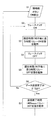
図7を用いて、認証制御動作の概略を説明する。
(4) Authentication control operation (4-1) Overall schematic control operation The outline of the authentication control operation will be described with reference to FIG.
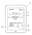
なお、認証制御動作時には、タブレット型コンピュータ3のディスプレイ9には、例えば、図11に示すように、承認を求める書類情報と、電子印鑑を押し当てる部分である第1印鑑押当部分7a、第2印鑑押当部分7b、第3印鑑押当部分7cが表示されている。
At the time of the authentication control operation, for example, as shown in FIG. 11, the
操作者が電子印鑑5をタブレット型コンピュータ3のタッチパネル7に押し付けると、タクトスイッチ39がオンされて、バッテリ29からマイコン制御部27に電力が供給される。これにより、マイコン制御部27がスイッチングリレー41に対して電力オンと電力オフとを繰り返す。電力オンによってスイッチングリレー41は連通状態になり、その結果、タッチパネル7にはタッチダウンが入力される。電力オフによってスイッチングリレー41は遮断状態になり、その結果、タッチパネル7にはタッチアップが入力される。
When the operator presses the
タッチダウン又はタッチアップが入力されると、タイマー部21が時間計測を開始する。なお、このときに、表示制御部15は、受信中であることの表示をディスプレイ9に表示させる。
When touchdown or touchup is input, the
認証部13は、タイマー部21からの情報に基づいて、タッチダウン又はタッチアップの時間間隔を入力データ記憶部17に記憶する。
The
以上のステップは、400ms以上のタッチアップを検出するまで繰り返される。そして、次に、認証部13は、入力データ記憶部17に保存された入力データに一致する認証データが認証データ記憶部19に存在するか否か、さらには入力データが電子印鑑5の押し当てられた箇所に正しく対応したものであるか否かを調べる。この照合作業により、用いられた電子印鑑5が正しいものか否かが判定される。用いられた電子印鑑5が正しい場合には、表示制御部15が、用いられた電子印鑑5に対応する印鑑画像を表示データ記憶部23から取り出し、それをディスプレイ9に表示させる。
The above steps are repeated until a touch-up of 400 ms or longer is detected. Next, the
(4−2)電子印鑑の制御動作
図7を用いて、電子印鑑5の制御を説明する。図7は、電子印鑑の動作フローチャートである。なお、以下の説明では、主に、電子印鑑5のマイコン制御部27(つまり、情報送信部27b)が動作主体である。
(4-2) Control Operation of Electronic Seal Stamp The control of the
ステップS1では、電子印鑑5がタッチパネル7に押されることで、タクトスイッチ39がオンされる。これにより、マイコン制御部27にバッテリ29から電力が供給される。これにより、ステップS2〜S8において、マイコン制御部27は、スイッチングリレー41に所定の電力オンオフの組み合わせからなる制御信号を送信開始する。
In step S1, the
ステップS2では、マイコン制御部27は、スイッチングリレー41をオンにする。
In step S2, the
ステップS3では、マイコン制御部27は、スイッチングリレー41を所定時間オン状態に維持する。
In step S3, the
ステップS4では、マイコン制御部27は、スイッチングリレー41をオフにする。
In step S4, the
ステップS5では、マイコン制御部27は、スイッチングリレー41を所定時間オフ状態に維持する。
In step S5, the
ステップS6では、マイコン制御部27は、データ送信完了か否かを判断する。データ送信完了でなければ、プロセスはステップS2に戻る。データ送信完了であれば、プロセスはステップS7に移行する。
In step S6, the
ステップS7では、マイコン制御部27は、スイッチングリレー41を送信完了間隔である400msだけオフ状態を維持する。ステップS8が終了すると、プロセスはステップS1に戻り、次に電子印鑑5がタッチパネル7に押されるのを待つ。
In step S7, the
(4−3)タブレット型コンピュータの制御動作
図8を用いて、タブレット型コンピュータ3の制御を説明する。図8は、タブレット型コンピュータの動作フローチャートである。なお、以下の説明では、主に、タブレット型コンピュータ3の制御部11が動作主体である。
(4-3) Control Operation of
ステップS11では、タイマー部21が動作可能となる。
In step S11, the
ステップS12では、認証部13は、タッチパネル7に入力されたタッチダウン又はタッチアップが受信されるの待つ。
In step S <b> 12, the
ステップS13では、認証部13は、タッチダウン又はタッチアップの時間間隔を入力データ記憶部17の第1配列に記憶する。
In step S <b> 13, the
ステップS14では、認証部13は、タイマー部21の値をリセットさせる。
In step S <b> 14, the
ステップS15では、認証部13は、入力データ記憶部17の第1配列に記憶された最新のタッチダウン又はタッチアップの時間間隔が400ms付近であるか否かを判断する。400ms付近であれば、プロセスはステップS16に移行する。400ms付近でなければ、プロセスはステップS12に戻り、次のタッチダウン又はタッチアップが入力されるのを待つ。
In step S15, the
ステップS16では、認証部13は、入力データ記憶部17の第1配列に記憶された一連のタッチダウン又はタッチアップの時間間隔に関して、200ms付近のものについては入力データ記憶部17の第2配列に「1」を格納し、100ms付近のものについては入力データ記憶部17の第2配列に「0」を格納する。これにより、電子印鑑5によって生じた静電量変化のパターンが、1と0の配列パターンとして入力データ記憶部17に保存される。
In step S <b> 16, the
図9及び図10を用いて、タッチダウンとタッチアップのパターンと受信側の解釈との関係を説明する。図9は、第1の種類の電子印鑑による識別情報を示すグラフであり、図10は第2の種類の電子印鑑による識別情報を示すグラフである。 The relationship between touchdown and touchup patterns and interpretation on the receiving side will be described with reference to FIGS. 9 and 10. FIG. 9 is a graph showing identification information by the first type electronic seal stamp, and FIG. 10 is a graph showing identification information by the second type electronic seal stamp.
図9に示された電子印鑑5の所定パターンは、接地0.1秒−非接地0.1秒−接地0.2秒−非接地0.2秒−接地0.1秒−非接地0.4秒の繰り返しである。これにより、タブレット型コンピュータ3の入力データ記憶部17には、「00110」が保存される。非接地0.4秒は、タブレット型コンピュータ3には、終了信号として解釈される。
The predetermined pattern of the
図10に示された電子印鑑5の所定パターンは、接地0.2秒−非接地0.2秒−接地0.1秒−非接地0.1秒−接地0.1秒−非接地0.4秒の繰り返しである。これにより、タブレット型コンピュータ3の入力データ記憶部17には、「11000」が保存される。非接地0.4秒は、タブレット型コンピュータ3には、終了信号として解釈される。
The predetermined pattern of the
この実施形態では、スイッチングリレーをマイコン制御することで、人間の指では実現できないスピードで特定のタッチパターンを構成するタッチアップ及びタッチダウンをタブレット型コンピュータ3に入力している。
In this embodiment, by controlling the switching relay with a microcomputer, touch-up and touch-down constituting a specific touch pattern are input to the
特に、タブレット型コンピュータ3が人間の指の押し方(位置、数、面積、押圧力)にのみ反応するように設定されるいるような場合でも、電子印鑑5を人間の指と同等の機能を実現するように構成することで、そのようなタブレット型コンピュータ3に識別情報を入力することができる。
In particular, even when the
また、操作者は、電子印鑑5をタブレット型コンピュータ3に押し付けるときに、通常の印鑑を紙に押すときと同様の感覚が得られるので、電子印鑑5を用いることに抵抗感を感じない。
Further, when the operator presses the
さらに、電子印鑑5がタブレット型コンピュータ3に押し当てられてタッチパネル7から電子印鑑5側に反力が作用した瞬間から、電子印鑑5から識別信号がタブレット型コンピュータ3に入力される。つまり、操作者が電子印鑑5をタブレット型コンピュータ3に押し付けた状態を維持することで、電子印鑑5とタブレット型コンピュータ3の通信が安定的に行われる。
Further, an identification signal is input from the
ステップS17では、認証部13は、入力データ記憶部17に保存された識別情報に対応する認証データが認証データ記憶部19に保存されているか否か、さらには当該入力データが電子印鑑5の押し当てられた箇所に正しく対応したものであるか否かを調べる。入力データが電子印鑑5の押し当てられた箇所に正しく対応していない場合とは、例えば部長印が押されるべき箇所に課長印が押された場合である。両方ともYesの場合は、プロセスはステップS18に移行する。一方でもNoの場合は、プロセスはステップS19に移行する。
In step S <b> 17, the
ステップS18では、認証部13からの指示に基づいて、表示制御部15は、対応する印鑑の印鑑画像データを表示データ記憶部23から取り出して、ディスプレイ9に表示する。例えば、図11に示すように、山本印である電子印鑑5が第1印鑑押当部分7aに正しく押されると、第1印鑑押当部分7aに「山本」の印鑑画像が表示される。
In step S <b> 18, based on an instruction from the
このように、タブレット型コンピュータ3は、電子印鑑5からの識別情報を認証した後に、電子印鑑5を特定する情報を表示する。つまり、例えば、判子を紙に押したときに印鑑画像が映るように、電子印鑑5を特定する情報がタブレット型コンピュータ3の表面に表示される。これにより、操作者は、自分の電子印鑑5による認証が正しく行われた場合に、タブレット型コンピュータ3の動作に基づいてそのことを知ることができる
なお、認証部13は、印鑑画像を付加して文書ファイルを保存する。
Thus, after authenticating the identification information from the
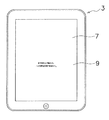
ステップS19では、認証部13は、表示制御部15に「承認不可」の表示をディスプレイ9に表示させる。例えば、図12に示すように、書類の承認不可が表示される。なお、図12は、承認不可表示状態にあるタブレット型コンピュータの平面図である。
In step S <b> 19, the
(5)特徴
上記実施形態は、下記のように表現可能である。
(5) Features The above embodiment can be expressed as follows.
(A)認証システム1は、タブレット型コンピュータ3(静電容量方式のタッチパネル装置の一例)と、電子印鑑5(入力装置の一例)とを備えている。電子印鑑5は、タブレット型コンピュータ3に対して、静電容量の変化からなる識別情報を入力可能である。タブレット型コンピュータ3は、入力された識別情報に対して認証を行う。
(A) The
このシステムでは、電子印鑑5が静電容量の変化からなる識別情報をタブレット型コンピュータ3に対して入力すれば、タブレット型コンピュータ3が入力された識別情報に対して認証を行う。このように簡単な構造及び操作によって、タブレット型コンピュータ3による認証が可能になっている。
In this system, when the
(B)タブレット型コンピュータ3は、電子印鑑5からの識別情報を認証した後に、電子印鑑5ごとに異なる動作を実行する。
(B) After authenticating the identification information from the
このシステムでは、操作者は、自分が用いた電子印鑑5による認証が正しく行われた場合に、タブレット型コンピュータ3の動作に基づいてそのことを知ることができる。
In this system, the operator can know the fact based on the operation of the
(C)タブレット型コンピュータ3は、電子印鑑5からの識別情報を認証した後に、電子印鑑5を特定する情報を表示する。
(C) After authenticating the identification information from the
このシステムでは、例えば、判子を紙に押したときに印鑑画像が映るように、電子印鑑5を特定する情報がタブレット型コンピュータ3の表面に表示される。これにより、操作者は、自分が用いた電子印鑑5による認証が正しく行われた場合に、タブレット型コンピュータ3の動作に基づいてそのことを知ることができる。
(D)タブレット型コンピュータ3は、静電容量方式のタッチパネル7と、入力データ記憶部17(記憶部の一例)と、ディスプレイ9(表示部の一例)とを備えている。入力データ記憶部17は、タッチパネル7が検出した識別情報を記憶する。ディスプレイ9は、入力データ記憶部17に記憶された識別情報に基づいて、電子印鑑5に対応する画像を表示する。
In this system, for example, information for specifying the
(D) The
このシステムでは、入力データ記憶部17に記憶された識別情報に基づいて、電子印鑑5に対応する画像が表示される。これにより、操作者は、自分が用いた電子印鑑5による認証が正しく行われた場合に、タブレット型コンピュータ3の表示に基づいてそのことを知ることができる。
(E)電子印鑑5は、導電性スポンジ31(第1導電性接触部の一例)と、銅釘43(第2導電性接触部の一例)と、スイッチングリレー41(断続器の一例)と、マイコン制御部27(制御部)とを有する。導電性スポンジ31は、タブレット型コンピュータ3の表面に接触する。銅釘43は、人間の指が接触可能である。スイッチングリレー41は、導電性スポンジ31と銅釘43との間に設けられている。制御部は、スイッチングリレー41を所定のパターンで断続動作させる。
In this system, an image corresponding to the
(E) The
このシステムでは、マイコン制御部27がスイッチングリレー41を所定のパターンで断続動作させると、導電性スポンジ31と銅釘43は連通と切断を繰り返す。これにより、所定のパターンの静電容量の変化からなる識別情報がタブレット型コンピュータ3によって検出される。
In this system, when the
(F)導電性スポンジ31は、弾性変形可能な部材である。
(F) The
このシステムでは、導電性スポンジ31が全体的にタブレット型コンピュータ3の表面に接触するので、識別情報が安定的にタブレット型コンピュータ3に入力される。
In this system, since the
(G)タクトスイッチ39(スイッチの一例)は、導電性スポンジ31がタブレット型コンピュータ3の表面からの反力によって押されることでマイコン制御部27を動作状態にする。
(G) The tact switch 39 (an example of a switch) brings the
このシステムでは、操作者が電子印鑑5をタブレット型コンピュータ3の表面に押し付けることで、タクトスイッチ39がマイコン制御部27を動作状態にして、その結果、電子印鑑5からタブレット型コンピュータ3に識別情報が入力される。つまり、操作者が電子印鑑5をタブレット型コンピュータ3に押し付けた状態を維持することで、電子印鑑5とタブレット型コンピュータ3の通信が安定的に行われる。
In this system, when the operator presses the
(H)電子印鑑5は、スイッチングリレー41を収容しており、先端に導電性スポンジ31が露出した状態で配置され、操作者の指が接触する位置に銅釘43が露出した状態で配置される筐体25をさらに有している。
(H) The
このシステムでは、操作者が筐体25を持つときに指が銅釘43に接触するので、操作者は、銅釘43に触れることをあまり意識することなく、電子印鑑5を用いて識別情報をタブレット型コンピュータ3に入力できる。
In this system, since the finger contacts the
(6)他の実施形態
以上、本発明の一実施形態について説明したが、本発明は上記実施形態に限定されるものではなく、発明の要旨を逸脱しない範囲で種々の変更が可能である。特に、本明細書に書かれた複数の実施形態及び変形例は必要に応じて任意に組み合わせ可能である。
(6) Other Embodiments Although one embodiment of the present invention has been described above, the present invention is not limited to the above embodiment, and various modifications can be made without departing from the scope of the invention. In particular, a plurality of embodiments and modifications described in this specification can be arbitrarily combined as necessary.
(a)前記実施形態では電子印鑑のタッチパネルに対する接触面を導電性スポンジにしたが、導電性材料からなる柔軟性を有する部材であればスポンジ以外であってもよい。例えば、導電性のゴムを用いてもよい。 (A) In the said embodiment, although the contact surface with respect to the touchscreen of an electronic seal stamp was made into conductive sponge, if it is a member which has the softness | flexibility which consists of conductive materials, it may be other than sponge. For example, conductive rubber may be used.
(b)前記実施形態では電子印鑑がタッチパネルに押されたことをタクトスイッチによって検出したが、感圧センサ等の他の手段を用いて電子印鑑がタッチパネルに押されたことを検出してもよい。 (B) Although the tact switch detects that the electronic seal stamp has been pressed on the touch panel in the embodiment, it may be detected that the electronic seal stamp has been pressed on the touch panel using other means such as a pressure sensor. .
(c)前記実施形態では認証システムは電子的に記録された書類の承認作業である印鑑押捺に用いられたが、他の認証作業、例えば、装置の利用、書類の閲覧、施設への入場の権限があることを認証する作業に用いられてもよい。 (C) In the above embodiment, the authentication system is used for seal stamping, which is an approval operation for electronically recorded documents. However, other authentication operations, for example, use of the apparatus, browsing of documents, entrance of facilities, etc. It may be used for the task of authenticating that there is authority.
(d)前記実施形態では入力装置は電子印鑑であったが、パスワード入力装置、身分証明装置であってもよい。 (D) In the above embodiment, the input device is an electronic seal stamp, but it may be a password input device or an identification device.
(e)前記実施形態では承認者の識別情報は名字であったが、役職、コード番号等を含んでいてもよい。また、識別情報としては、コード番号だけであってもよい。 (E) In the above-described embodiment, the approver's identification information is a surname, but may include a job title, a code number, and the like. Further, the identification information may be only a code number.
(f)前記実施形態ではタブレット型コンピュータの認証部は識別信号のタッチダウンとタッチアップの両方の時間間隔を計測していたが、タッチダウンとタッチアップの一方の時間のみを計測するようにしてもよい。 (F) In the above embodiment, the authentication unit of the tablet computer measures the time interval between the touchdown and the touchup of the identification signal. However, only one time of the touchdown and the touchup is measured. Also good.
(g)前記実施形態では電子印鑑の押圧面は無印の平坦面であったが、印影がプリントされていてもよいし、朱肉を用いて通常の印鑑としても機能する印影が刻印されていてもよい。 (G) Although the pressing surface of the electronic seal stamp is an unmarked flat surface in the above-described embodiment, the seal stamp may be printed, or a stamp that also functions as a normal seal stamp is printed using vermilion. Good.
(h)前記実施形態では使用された電子印鑑のみを認証していたが、電子印鑑に加えて電子印鑑を実際に利用した使用者を特定するようにしてもよい。その場合には、例えば、電子印鑑に指紋認証装置が設けられている。指紋認証装置は、電子印鑑を持った操作者の指紋を検出して、検出データと保存してある指紋データとを照合する。そして、指紋認証装置は、照合結果に基づいて特定の人物を特定する。そして、データ送信部は、印鑑固有のデータに加えて人物特定データを外部に送信する。 (H) Although only the used electronic seal stamp was authenticated in the said embodiment, you may make it identify the user who actually utilized the electronic seal stamp in addition to the electronic seal stamp. In that case, for example, a fingerprint authentication device is provided in the electronic seal stamp. The fingerprint authentication device detects the fingerprint of the operator holding the electronic seal stamp, and collates the detected data with the stored fingerprint data. Then, the fingerprint authentication device specifies a specific person based on the collation result. The data transmission unit transmits the person specifying data to the outside in addition to the data unique to the seal.
タブレット型コンピュータは、受信したデータの認証後に、必要に応じて、印影とともに操作者の情報(氏名、役職等)を表示する。 After authenticating the received data, the tablet computer displays the operator's information (name, title, etc.) together with the seal as necessary.
(i)前記実施形態ではタッチパネル装置としてタブレット型コンピュータを採用したが、本発明は他のコンピュータにも適用できる。 (I) Although the tablet computer is adopted as the touch panel device in the above embodiment, the present invention can be applied to other computers.
本発明は、静電容量方式のタッチパネル装置を用いた認証システムに広く適用できる。 The present invention can be widely applied to an authentication system using a capacitive touch panel device.
1 認証システム
3 タブレット型コンピュータ(タッチパネル装置)
5 電子印鑑(入力装置)
7 タッチパネル
9 ディスプレイ(表示部)
11 制御部
13 認証部
15 表示制御部
17 入力データ記憶部(記憶部)
19 認証データ記憶部
21 タイマー部
23 表示データ記憶部
25 筐体
27 マイコン制御部(制御部)
27a 識別情報記憶部
27b 情報送信部
29 バッテリ
31 導電性スポンジ(第1導電性接触部)
33 台座
39 タクトスイッチ(スイッチ)
41 スイッチングリレー(断続器)
43 銅釘(第2導電性接触部)
1
5 Electronic seal stamp (input device)
7
11
19 Authentication
27a Identification
33
41 Switching relay (interrupter)
43 Copper nail (second conductive contact part)
Claims (10)
前記タッチパネル装置に対して、静電容量の変化からなる識別情報を入力可能な入力装置と、を備え、
前記タッチパネル装置は、入力された前記識別情報に対して認証を行う、認証システム。 A capacitive touch panel device;
An input device capable of inputting identification information consisting of a change in capacitance to the touch panel device,
The touch panel device is an authentication system that authenticates the input identification information.
静電容量方式のタッチパネルと、
前記タッチパネルが検出した前記識別情報を記憶する記憶部と、
前記記憶部に記憶された前記識別情報に基づいて、前記入力装置に対応する画像を表示する表示部と、を有している、請求項3に記載の認証システム。 The touch panel device
A capacitive touch panel,
A storage unit for storing the identification information detected by the touch panel;
The authentication system according to claim 3, further comprising: a display unit that displays an image corresponding to the input device based on the identification information stored in the storage unit.
前記タッチパネル装置の表面に接触するための第1導電性接触部と、
人間の指が接触可能な第2導電性接触部と、
前記第1導電性接触部と前記第2導電性接触部との間に設けられた断続器と、
前記断続器を所定のパターンで断続動作させる制御部とを有する、請求項1から4のいずれか1項に記載の認証システム。 The input device is:
A first conductive contact portion for contacting the surface of the touch panel device;
A second conductive contact that can be contacted by a human finger;
An interrupter provided between the first conductive contact portion and the second conductive contact portion;
5. The authentication system according to claim 1, further comprising: a control unit configured to intermittently operate the interrupter in a predetermined pattern.
前記タッチパネル装置の表面に接触するための第1導電性接触部と、
人間の指が接触可能な第2導電性接触部と、
前記第1導電性接触部と前記第2導電性接触部との間に設けられた断続器と、
前記断続器を所定のパターンで断続動作させる制御部と、
備えた入力装置。 An input device capable of inputting identification information consisting of a change in capacitance to a capacitive touch panel device,
A first conductive contact portion for contacting the surface of the touch panel device;
A second conductive contact that can be contacted by a human finger;
An interrupter provided between the first conductive contact portion and the second conductive contact portion;
A controller for intermittently operating the interrupter in a predetermined pattern;
Provided input device.
前記識別情報が入力されたときに識別情報を検出するステップと、
前記識別情報からタッチダウン又はタッチアップの時間間隔を計測するステップと、
計測結果を認証データと照合するステップと、
照合結果を報知するステップと、を含む方法をコンピュータに実行させる認証プログラム。 An authentication program for authenticating identification information consisting of a change in capacitance in a capacitive touch panel device,
Detecting the identification information when the identification information is input;
Measuring a time interval of touchdown or touchup from the identification information; and
Checking the measurement result against the authentication data;
An authentication program for causing a computer to execute a method including the step of notifying a verification result.
Priority Applications (1)
| Application Number | Priority Date | Filing Date | Title |
|---|---|---|---|
| JP2010265778A JP2012118637A (en) | 2010-11-29 | 2010-11-29 | Authentication system, input device, and authentication program |
Applications Claiming Priority (1)
| Application Number | Priority Date | Filing Date | Title |
|---|---|---|---|
| JP2010265778A JP2012118637A (en) | 2010-11-29 | 2010-11-29 | Authentication system, input device, and authentication program |
Publications (1)
| Publication Number | Publication Date |
|---|---|
| JP2012118637A true JP2012118637A (en) | 2012-06-21 |
Family
ID=46501409
Family Applications (1)
| Application Number | Title | Priority Date | Filing Date |
|---|---|---|---|
| JP2010265778A Pending JP2012118637A (en) | 2010-11-29 | 2010-11-29 | Authentication system, input device, and authentication program |
Country Status (1)
| Country | Link |
|---|---|
| JP (1) | JP2012118637A (en) |
Cited By (48)
| Publication number | Priority date | Publication date | Assignee | Title |
|---|---|---|---|---|
| JP2012256246A (en) * | 2011-06-09 | 2012-12-27 | Cross-Aid Co Ltd | Conductive seal for electrostatic capacity type touch panel, and conductive seal processing system for using the same |
| KR101305413B1 (en) | 2013-05-29 | 2013-09-06 | 최영우 | Touch stamp and system and method for authentication using the same |
| JP2014089528A (en) * | 2012-10-29 | 2014-05-15 | Duplo Seiko Corp | Seal, seal authentication method, seal authentication system and seal authentication program |
| WO2014077657A1 (en) * | 2012-11-19 | 2014-05-22 | 12Cm | Method and system for authenticating stamp touch |
| KR101414998B1 (en) | 2014-05-12 | 2014-07-04 | 주식회사 디벨로퍼스헤븐 | Smart stamp and smart stamp system |
| WO2014157170A1 (en) * | 2013-03-25 | 2014-10-02 | 株式会社シアーズ | Simple authentication means, content updating program, and content updating system |
| KR20140123147A (en) * | 2013-04-10 | 2014-10-22 | 원투씨엠 주식회사 | Melt-Bonding type Touch Device |
| KR20140144767A (en) * | 2013-06-11 | 2014-12-22 | 원투씨엠 주식회사 | Method for Controlling Application by using Simultaneous Touch |
| KR101488321B1 (en) * | 2014-05-26 | 2015-01-30 | 이광용 | An interaction between a piece and an electronic device through touch signals |
| KR101493282B1 (en) * | 2013-09-09 | 2015-02-13 | 원투씨엠 주식회사 | A Capacitive Touch Device |
| KR101498503B1 (en) * | 2014-08-11 | 2015-03-05 | 원투씨엠 주식회사 | Method for Identifying Capacitive Multi-Touch |
| KR20150029248A (en) * | 2013-09-09 | 2015-03-18 | 원투씨엠 주식회사 | A Touch Handstamp for Providing Synchronous Touch by using Alien Touch Part |
| KR20150029247A (en) * | 2013-09-09 | 2015-03-18 | 원투씨엠 주식회사 | A Touch Handstamp for Including Alien Touch Part |
| KR20150029249A (en) * | 2013-09-09 | 2015-03-18 | 원투씨엠 주식회사 | A Touch Handstamp for Synchronous Touch |
| KR20150029250A (en) * | 2013-09-09 | 2015-03-18 | 원투씨엠 주식회사 | A Touch Handstamp for Synchronous Touch including Multiple Guide Part |
| KR20150029245A (en) * | 2013-09-09 | 2015-03-18 | 원투씨엠 주식회사 | A Touch Handstamp for Providing Exact Synchronous Touch |
| KR20150029244A (en) * | 2013-09-09 | 2015-03-18 | 원투씨엠 주식회사 | A Touch Handstamp for Including Alien Contact Area |
| KR20150029243A (en) * | 2013-09-09 | 2015-03-18 | 원투씨엠 주식회사 | A Touch Handstamp for Providing Synchronous Touch |
| WO2015053563A1 (en) * | 2013-10-08 | 2015-04-16 | 12Cm | Method for authenticating capacitive touch |
| KR20150045861A (en) * | 2013-10-21 | 2015-04-29 | 원투씨엠 주식회사 | A Touch Handstamp for Providing Free-Style Touch Certification |
| KR20150045856A (en) * | 2013-10-21 | 2015-04-29 | 원투씨엠 주식회사 | A Touch Handstamp for Including Insertion type Touch Part |
| KR20150045857A (en) * | 2013-10-21 | 2015-04-29 | 원투씨엠 주식회사 | A Touch Handstamp for Providing a Seal type Touch by using Insertion type Touch Part |
| KR20150045860A (en) * | 2013-10-21 | 2015-04-29 | 원투씨엠 주식회사 | A Touch Handstamp for Providing Touch Certification |
| KR20150045849A (en) * | 2013-10-21 | 2015-04-29 | 원투씨엠 주식회사 | A Touch Handstamp for Providing a Seal type Touch Certification between Alien Device |
| KR20150045852A (en) * | 2013-10-21 | 2015-04-29 | 원투씨엠 주식회사 | A Touch Handstamp for Providing Certification Touch |
| WO2015076605A1 (en) * | 2013-11-22 | 2015-05-28 | 모지도코화이어코리아 유한회사 | Touch and near field communication-based electronic stamp and electronic seal authentication system using same |
| KR20150059706A (en) * | 2013-11-23 | 2015-06-02 | 원투씨엠 주식회사 | A Handstamp for Touch |
| KR20150059707A (en) * | 2013-11-23 | 2015-06-02 | 원투씨엠 주식회사 | Touch Stamp for Rolling type Touch |
| KR20150089451A (en) * | 2014-01-28 | 2015-08-05 | 원투씨엠 주식회사 | Method for Providing Customized Service by using Stamp Touch |
| KR20150089454A (en) * | 2014-01-28 | 2015-08-05 | 원투씨엠 주식회사 | Method for Providing Service for Exhibition Center by using Stamp Touch |
| KR20150089453A (en) * | 2014-01-28 | 2015-08-05 | 원투씨엠 주식회사 | Method for Providing Web Access Service by using Stamp Touch |
| KR20150090764A (en) * | 2014-01-29 | 2015-08-06 | 원투씨엠 주식회사 | Method for Selecting Optimized Card by using Stamp Touch |
| KR101545320B1 (en) * | 2013-06-11 | 2015-08-20 | 원투씨엠 주식회사 | Method for Selecting Information by using Capacitive Multi-Touch |
| JP2015201211A (en) * | 2013-05-22 | 2015-11-12 | 株式会社Leonis&Co. | electronic ticket system and program |
| KR20150134196A (en) * | 2014-05-21 | 2015-12-01 | 원투씨엠 주식회사 | A Touch Unitfor Providing Synchronous Touch Certification |
| KR20150134195A (en) * | 2014-05-21 | 2015-12-01 | 원투씨엠 주식회사 | A Touch Unit for Providing Touch Certification between Alien Device |
| KR20150145931A (en) * | 2014-06-20 | 2015-12-31 | 원투씨엠 주식회사 | Touch Module for Multiple Touch Equipped Touch Membrane |
| KR20160010754A (en) * | 2014-07-17 | 2016-01-28 | 원투씨엠 주식회사 | Touch Module for Multiple Order Touch Equipped Touch and Protective Membrane |
| KR20160010755A (en) * | 2014-07-17 | 2016-01-28 | 원투씨엠 주식회사 | Touch Module for Multiple Order Touch Equipped Touch and Protective Membrane |
| WO2016021959A1 (en) * | 2014-08-07 | 2016-02-11 | (주) 인터랙티비 | Electronic stamp, electronic stamp service providing system using same, and method therefor |
| WO2016021810A1 (en) * | 2014-08-04 | 2016-02-11 | 에스케이텔레콤 주식회사 | Stamper, and terminal and operation method thereof |
| JP2016042396A (en) * | 2012-09-28 | 2016-03-31 | スタンプ ピーティーイー リミテッド | Input system and input device using capacitive touch |
| JP2017504117A (en) * | 2014-01-09 | 2017-02-02 | 2ギャザー インコーポレイテッド | Apparatus and method for forming identification pattern for touch screen |
| WO2017115437A1 (en) * | 2015-12-28 | 2017-07-06 | 泰和 西尾 | Input system |
| US10223692B2 (en) | 2012-11-28 | 2019-03-05 | Mozido Corfire-Korea, LTD. | Method for setting temporary payment card and mobile device applying the same |
| KR102059201B1 (en) * | 2013-04-10 | 2019-12-26 | 원투씨엠 주식회사 | Adhesive type Touch Device |
| KR102059199B1 (en) * | 2013-04-10 | 2019-12-26 | 원투씨엠 주식회사 | A Prefabricated Touch Device |
| KR102059200B1 (en) * | 2013-04-10 | 2019-12-26 | 원투씨엠 주식회사 | Cutting type Touch Device |
Citations (12)
| Publication number | Priority date | Publication date | Assignee | Title |
|---|---|---|---|---|
| JPH0589220A (en) * | 1991-09-30 | 1993-04-09 | Nkk Corp | Electronic imprinter |
| JPH10171580A (en) * | 1996-12-13 | 1998-06-26 | Mitsubishi Pencil Co Ltd | Input pen for electrostatic capacity type coordinate input pad |
| JPH10187329A (en) * | 1996-12-25 | 1998-07-14 | Alps Electric Co Ltd | Input pen |
| JP2001307102A (en) * | 2000-04-27 | 2001-11-02 | Fujitsu Ltd | Personal authentication system and method using living body information and registration device, authentication device and pattern information input medium for the system |
| JP2002318904A (en) * | 2001-04-23 | 2002-10-31 | Toshiba Corp | Series input device, individual authentication system and series collation system, input series genertion method, individual authentication method and series collation method, and program |
| JP2005296483A (en) * | 2004-04-15 | 2005-10-27 | Taito Corp | Card recognition game system using electrostatic capacity sensor |
| JP2009070416A (en) * | 2009-01-05 | 2009-04-02 | Sony Computer Entertainment Inc | Control system and control method |
| US20090121878A1 (en) * | 2007-11-14 | 2009-05-14 | Alexan Co., Ltd | Electronic seal with radio frequency identification |
| WO2010005662A1 (en) * | 2008-06-16 | 2010-01-14 | Qualcomm Incorporated | Method and system for graphical passcode security |
| JP2010198309A (en) * | 2009-02-25 | 2010-09-09 | Kyocera Corp | Data processing apparatus with biometric authentication function |
| JP2011509039A (en) * | 2008-01-04 | 2011-03-17 | レーウン パク | Crime prevention system |
| JP2012003734A (en) * | 2010-06-17 | 2012-01-05 | Yoichi Ochiai | Icon on capacitance type touch sensor |
-
2010
- 2010-11-29 JP JP2010265778A patent/JP2012118637A/en active Pending
Patent Citations (12)
| Publication number | Priority date | Publication date | Assignee | Title |
|---|---|---|---|---|
| JPH0589220A (en) * | 1991-09-30 | 1993-04-09 | Nkk Corp | Electronic imprinter |
| JPH10171580A (en) * | 1996-12-13 | 1998-06-26 | Mitsubishi Pencil Co Ltd | Input pen for electrostatic capacity type coordinate input pad |
| JPH10187329A (en) * | 1996-12-25 | 1998-07-14 | Alps Electric Co Ltd | Input pen |
| JP2001307102A (en) * | 2000-04-27 | 2001-11-02 | Fujitsu Ltd | Personal authentication system and method using living body information and registration device, authentication device and pattern information input medium for the system |
| JP2002318904A (en) * | 2001-04-23 | 2002-10-31 | Toshiba Corp | Series input device, individual authentication system and series collation system, input series genertion method, individual authentication method and series collation method, and program |
| JP2005296483A (en) * | 2004-04-15 | 2005-10-27 | Taito Corp | Card recognition game system using electrostatic capacity sensor |
| US20090121878A1 (en) * | 2007-11-14 | 2009-05-14 | Alexan Co., Ltd | Electronic seal with radio frequency identification |
| JP2011509039A (en) * | 2008-01-04 | 2011-03-17 | レーウン パク | Crime prevention system |
| WO2010005662A1 (en) * | 2008-06-16 | 2010-01-14 | Qualcomm Incorporated | Method and system for graphical passcode security |
| JP2009070416A (en) * | 2009-01-05 | 2009-04-02 | Sony Computer Entertainment Inc | Control system and control method |
| JP2010198309A (en) * | 2009-02-25 | 2010-09-09 | Kyocera Corp | Data processing apparatus with biometric authentication function |
| JP2012003734A (en) * | 2010-06-17 | 2012-01-05 | Yoichi Ochiai | Icon on capacitance type touch sensor |
Cited By (84)
| Publication number | Priority date | Publication date | Assignee | Title |
|---|---|---|---|---|
| JP2012256246A (en) * | 2011-06-09 | 2012-12-27 | Cross-Aid Co Ltd | Conductive seal for electrostatic capacity type touch panel, and conductive seal processing system for using the same |
| JP2016042396A (en) * | 2012-09-28 | 2016-03-31 | スタンプ ピーティーイー リミテッド | Input system and input device using capacitive touch |
| JP2018133117A (en) * | 2012-09-28 | 2018-08-23 | キュー−アドバタイジング カンパニー,リミテッド | Input system and input device using capacitive touch |
| JP2014089528A (en) * | 2012-10-29 | 2014-05-15 | Duplo Seiko Corp | Seal, seal authentication method, seal authentication system and seal authentication program |
| JP2017188144A (en) * | 2012-11-19 | 2017-10-12 | 12シイエム | Method and system for authenticating stamp touch |
| WO2014077657A1 (en) * | 2012-11-19 | 2014-05-22 | 12Cm | Method and system for authenticating stamp touch |
| US10824708B2 (en) | 2012-11-19 | 2020-11-03 | 12Cm Global Pte. Ltd. | Method and system for authenticating stamp touch |
| US10223692B2 (en) | 2012-11-28 | 2019-03-05 | Mozido Corfire-Korea, LTD. | Method for setting temporary payment card and mobile device applying the same |
| WO2014157170A1 (en) * | 2013-03-25 | 2014-10-02 | 株式会社シアーズ | Simple authentication means, content updating program, and content updating system |
| KR20140123147A (en) * | 2013-04-10 | 2014-10-22 | 원투씨엠 주식회사 | Melt-Bonding type Touch Device |
| KR102059201B1 (en) * | 2013-04-10 | 2019-12-26 | 원투씨엠 주식회사 | Adhesive type Touch Device |
| KR102059199B1 (en) * | 2013-04-10 | 2019-12-26 | 원투씨엠 주식회사 | A Prefabricated Touch Device |
| KR102059200B1 (en) * | 2013-04-10 | 2019-12-26 | 원투씨엠 주식회사 | Cutting type Touch Device |
| KR102086855B1 (en) * | 2013-04-10 | 2020-03-10 | 원투씨엠 주식회사 | Melt-Bonding type Touch Device |
| JP2021012733A (en) * | 2013-05-22 | 2021-02-04 | playground株式会社 | Terminal device and program |
| JP2015201211A (en) * | 2013-05-22 | 2015-11-12 | 株式会社Leonis&Co. | electronic ticket system and program |
| JP7033823B2 (en) | 2013-05-22 | 2022-03-11 | playground株式会社 | Terminal devices and programs. |
| KR101305413B1 (en) | 2013-05-29 | 2013-09-06 | 최영우 | Touch stamp and system and method for authentication using the same |
| KR20140144767A (en) * | 2013-06-11 | 2014-12-22 | 원투씨엠 주식회사 | Method for Controlling Application by using Simultaneous Touch |
| KR102144128B1 (en) * | 2013-06-11 | 2020-08-13 | 원투씨엠 주식회사 | Method for Controlling Application by using Simultaneous Touch |
| KR101545320B1 (en) * | 2013-06-11 | 2015-08-20 | 원투씨엠 주식회사 | Method for Selecting Information by using Capacitive Multi-Touch |
| KR102139834B1 (en) * | 2013-09-09 | 2020-07-30 | 원투씨엠 주식회사 | A Touch Handstamp for Providing Synchronous Touch by using Alien Touch Part |
| KR20150029244A (en) * | 2013-09-09 | 2015-03-18 | 원투씨엠 주식회사 | A Touch Handstamp for Including Alien Contact Area |
| KR102139832B1 (en) * | 2013-09-09 | 2020-07-30 | 원투씨엠 주식회사 | A Touch Handstamp for Providing Exact Synchronous Touch |
| KR102139833B1 (en) * | 2013-09-09 | 2020-07-30 | 원투씨엠 주식회사 | A Touch Handstamp for Including Alien Touch Part |
| KR102139835B1 (en) * | 2013-09-09 | 2020-07-30 | 원투씨엠 주식회사 | A Touch Handstamp for Synchronous Touch |
| KR102139830B1 (en) * | 2013-09-09 | 2020-07-30 | 원투씨엠 주식회사 | A Touch Handstamp for Providing Synchronous Touch |
| KR102149551B1 (en) * | 2013-09-09 | 2020-08-28 | 원투씨엠 주식회사 | A Touch Handstamp for Synchronous Touch including Multiple Guide Part |
| KR101493282B1 (en) * | 2013-09-09 | 2015-02-13 | 원투씨엠 주식회사 | A Capacitive Touch Device |
| KR20150029243A (en) * | 2013-09-09 | 2015-03-18 | 원투씨엠 주식회사 | A Touch Handstamp for Providing Synchronous Touch |
| KR102139831B1 (en) * | 2013-09-09 | 2020-07-30 | 원투씨엠 주식회사 | A Touch Handstamp for Including Alien Contact Area |
| KR20150029245A (en) * | 2013-09-09 | 2015-03-18 | 원투씨엠 주식회사 | A Touch Handstamp for Providing Exact Synchronous Touch |
| KR20150029250A (en) * | 2013-09-09 | 2015-03-18 | 원투씨엠 주식회사 | A Touch Handstamp for Synchronous Touch including Multiple Guide Part |
| KR20150029249A (en) * | 2013-09-09 | 2015-03-18 | 원투씨엠 주식회사 | A Touch Handstamp for Synchronous Touch |
| KR20150029247A (en) * | 2013-09-09 | 2015-03-18 | 원투씨엠 주식회사 | A Touch Handstamp for Including Alien Touch Part |
| KR20150029248A (en) * | 2013-09-09 | 2015-03-18 | 원투씨엠 주식회사 | A Touch Handstamp for Providing Synchronous Touch by using Alien Touch Part |
| US10175828B2 (en) | 2013-10-08 | 2019-01-08 | 12Cm Global Pte. Ltd. | Method for authenticating capacitive touch |
| WO2015053563A1 (en) * | 2013-10-08 | 2015-04-16 | 12Cm | Method for authenticating capacitive touch |
| KR102149552B1 (en) * | 2013-10-21 | 2020-08-28 | 원투씨엠 주식회사 | A Touch Handstamp for Providing a Seal type Touch Certification between Alien Device |
| KR20150045860A (en) * | 2013-10-21 | 2015-04-29 | 원투씨엠 주식회사 | A Touch Handstamp for Providing Touch Certification |
| KR102217351B1 (en) * | 2013-10-21 | 2021-02-18 | 원투씨엠 주식회사 | A Touch Handstamp for Providing Free-Style Touch Certification |
| KR102217350B1 (en) * | 2013-10-21 | 2021-02-18 | 원투씨엠 주식회사 | A Touch Handstamp for Providing Touch Certification |
| KR20150045852A (en) * | 2013-10-21 | 2015-04-29 | 원투씨엠 주식회사 | A Touch Handstamp for Providing Certification Touch |
| KR20150045849A (en) * | 2013-10-21 | 2015-04-29 | 원투씨엠 주식회사 | A Touch Handstamp for Providing a Seal type Touch Certification between Alien Device |
| KR20150045857A (en) * | 2013-10-21 | 2015-04-29 | 원투씨엠 주식회사 | A Touch Handstamp for Providing a Seal type Touch by using Insertion type Touch Part |
| KR20150045861A (en) * | 2013-10-21 | 2015-04-29 | 원투씨엠 주식회사 | A Touch Handstamp for Providing Free-Style Touch Certification |
| KR102149555B1 (en) * | 2013-10-21 | 2020-08-28 | 원투씨엠 주식회사 | A Touch Handstamp for Including Insertion type Touch Part |
| KR102149556B1 (en) * | 2013-10-21 | 2020-08-28 | 원투씨엠 주식회사 | A Touch Handstamp for Providing a Seal type Touch by using Insertion type Touch Part |
| KR20150045856A (en) * | 2013-10-21 | 2015-04-29 | 원투씨엠 주식회사 | A Touch Handstamp for Including Insertion type Touch Part |
| KR102149553B1 (en) * | 2013-10-21 | 2020-08-28 | 원투씨엠 주식회사 | A Touch Handstamp for Providing Certification Touch |
| WO2015076605A1 (en) * | 2013-11-22 | 2015-05-28 | 모지도코화이어코리아 유한회사 | Touch and near field communication-based electronic stamp and electronic seal authentication system using same |
| KR102159405B1 (en) * | 2013-11-23 | 2020-09-23 | 원투씨엠 주식회사 | A Handstamp for Touch |
| KR20150059706A (en) * | 2013-11-23 | 2015-06-02 | 원투씨엠 주식회사 | A Handstamp for Touch |
| KR102159406B1 (en) * | 2013-11-23 | 2020-09-23 | 원투씨엠 주식회사 | Touch Stamp for Rolling type Touch |
| KR20150059707A (en) * | 2013-11-23 | 2015-06-02 | 원투씨엠 주식회사 | Touch Stamp for Rolling type Touch |
| JP2017504117A (en) * | 2014-01-09 | 2017-02-02 | 2ギャザー インコーポレイテッド | Apparatus and method for forming identification pattern for touch screen |
| KR102165144B1 (en) * | 2014-01-28 | 2020-10-13 | 원투씨엠 주식회사 | Method for Providing Customized Service by using Stamp Touch |
| KR102150129B1 (en) * | 2014-01-28 | 2020-08-31 | 원투씨엠 주식회사 | Method for Providing Web Access Service by using Stamp Touch |
| KR20150089454A (en) * | 2014-01-28 | 2015-08-05 | 원투씨엠 주식회사 | Method for Providing Service for Exhibition Center by using Stamp Touch |
| KR20150089453A (en) * | 2014-01-28 | 2015-08-05 | 원투씨엠 주식회사 | Method for Providing Web Access Service by using Stamp Touch |
| KR20150089451A (en) * | 2014-01-28 | 2015-08-05 | 원투씨엠 주식회사 | Method for Providing Customized Service by using Stamp Touch |
| KR102151276B1 (en) * | 2014-01-28 | 2020-09-02 | 원투씨엠 주식회사 | Method for Providing Service for Exhibition Center by using Stamp Touch |
| KR20150090764A (en) * | 2014-01-29 | 2015-08-06 | 원투씨엠 주식회사 | Method for Selecting Optimized Card by using Stamp Touch |
| KR102149560B1 (en) | 2014-01-29 | 2020-08-28 | 원투씨엠 주식회사 | Method for Selecting Optimized Card by using Stamp Touch |
| KR101414998B1 (en) | 2014-05-12 | 2014-07-04 | 주식회사 디벨로퍼스헤븐 | Smart stamp and smart stamp system |
| KR20150134196A (en) * | 2014-05-21 | 2015-12-01 | 원투씨엠 주식회사 | A Touch Unitfor Providing Synchronous Touch Certification |
| KR102217360B1 (en) * | 2014-05-21 | 2021-02-18 | 원투씨엠 주식회사 | A Touch Unit for Providing Touch Certification between Alien Device |
| KR20150134195A (en) * | 2014-05-21 | 2015-12-01 | 원투씨엠 주식회사 | A Touch Unit for Providing Touch Certification between Alien Device |
| KR102217361B1 (en) * | 2014-05-21 | 2021-02-18 | 원투씨엠 주식회사 | A Touch Unitfor Providing Synchronous Touch Certification |
| KR101488321B1 (en) * | 2014-05-26 | 2015-01-30 | 이광용 | An interaction between a piece and an electronic device through touch signals |
| KR20150145931A (en) * | 2014-06-20 | 2015-12-31 | 원투씨엠 주식회사 | Touch Module for Multiple Touch Equipped Touch Membrane |
| KR102235890B1 (en) * | 2014-06-20 | 2021-04-02 | 원투씨엠 주식회사 | Touch Module for Multiple Touch Equipped Touch Membrane |
| KR20160010754A (en) * | 2014-07-17 | 2016-01-28 | 원투씨엠 주식회사 | Touch Module for Multiple Order Touch Equipped Touch and Protective Membrane |
| KR102326171B1 (en) * | 2014-07-17 | 2021-11-15 | 원투씨엠 주식회사 | Touch Module for Multiple Order Touch Equipped Touch and Protective Membrane |
| KR20160010755A (en) * | 2014-07-17 | 2016-01-28 | 원투씨엠 주식회사 | Touch Module for Multiple Order Touch Equipped Touch and Protective Membrane |
| KR102235887B1 (en) * | 2014-07-17 | 2021-04-05 | 원투씨엠 주식회사 | Touch Module for Multiple Order Touch Equipped Touch and Protective Membrane |
| WO2016021810A1 (en) * | 2014-08-04 | 2016-02-11 | 에스케이텔레콤 주식회사 | Stamper, and terminal and operation method thereof |
| KR101593955B1 (en) | 2014-08-04 | 2016-02-15 | 에스케이텔레콤 주식회사 | Stamper, and terminal and method thereof |
| CN106663259B (en) * | 2014-08-04 | 2021-03-23 | Sk电信有限公司 | Signet device, terminal and operation method thereof |
| US10515385B2 (en) | 2014-08-04 | 2019-12-24 | Sk Telecom Co., Ltd. | Stamper, terminal, and operation method thereof |
| WO2016021959A1 (en) * | 2014-08-07 | 2016-02-11 | (주) 인터랙티비 | Electronic stamp, electronic stamp service providing system using same, and method therefor |
| KR101498503B1 (en) * | 2014-08-11 | 2015-03-05 | 원투씨엠 주식회사 | Method for Identifying Capacitive Multi-Touch |
| JPWO2017115437A1 (en) * | 2015-12-28 | 2018-01-11 | 泰和 西尾 | Input system |
| WO2017115437A1 (en) * | 2015-12-28 | 2017-07-06 | 泰和 西尾 | Input system |
Similar Documents
| Publication | Publication Date | Title |
|---|---|---|
| JP2012118637A (en) | Authentication system, input device, and authentication program | |
| JP6952559B2 (en) | Handwritten information processing device, handwritten information processing method and program for handwritten information processing | |
| US8421610B2 (en) | Touch screen and method of operating the same | |
| KR101021440B1 (en) | Touch-input device, mobile device and control method thereof | |
| US8174372B2 (en) | Providing haptic feedback on a touch surface | |
| KR101562306B1 (en) | Tactile sensation providing apparatus and control method for tactile sensation providing apparatus | |
| KR100628652B1 (en) | Keypad for cellular phone | |
| CN102214035A (en) | Information presenting device, tactile sense presenting method, and program | |
| TW200822682A (en) | Multi-function key with scrolling | |
| CN107122088A (en) | A kind of 3D keystroke touch screens and electronic equipment | |
| US9201503B2 (en) | User interface device, image forming apparatus, user interface control method, and computer program product | |
| CN105210072A (en) | Portable device including a fingerprint scanner and method of controlling therefor | |
| CN102057345A (en) | Haptic user interface | |
| CN103034331B (en) | A kind of haptic feedback devices and terminal | |
| JP2001222378A (en) | Touch panel input device | |
| KR20120079595A (en) | Input error correction method and apparatus in input divice | |
| KR20140123895A (en) | Apparatus and method for providing tactile | |
| CN103777769A (en) | Input control method and device and electronic equipment | |
| JPWO2012141131A1 (en) | Touch panel device | |
| JP2011048571A (en) | Information processing device and information processing method | |
| KR20130069725A (en) | Tactile sensation providing apparatus and control method for tactile sensation providing apparatus | |
| US11112882B2 (en) | Input or control device with variable controls configuration | |
| JP5805378B2 (en) | Tactile presentation device | |
| CN105678199B (en) | Input device and information input method | |
| KR20160105825A (en) | System and method for recognizing objects with continuous capacitance sensing |
Legal Events
| Date | Code | Title | Description |
|---|---|---|---|
| A621 | Written request for application examination |
Free format text: JAPANESE INTERMEDIATE CODE: A621 Effective date: 20131127 |
|
| A977 | Report on retrieval |
Free format text: JAPANESE INTERMEDIATE CODE: A971007 Effective date: 20140731 |
|
| A131 | Notification of reasons for refusal |
Free format text: JAPANESE INTERMEDIATE CODE: A131 Effective date: 20140812 |
|
| A521 | Request for written amendment filed |
Free format text: JAPANESE INTERMEDIATE CODE: A523 Effective date: 20141009 |
|
| A131 | Notification of reasons for refusal |
Free format text: JAPANESE INTERMEDIATE CODE: A131 Effective date: 20141111 |
|
| A521 | Request for written amendment filed |
Free format text: JAPANESE INTERMEDIATE CODE: A523 Effective date: 20150107 |
|
| A02 | Decision of refusal |
Free format text: JAPANESE INTERMEDIATE CODE: A02 Effective date: 20150127 |