JP2012117728A - Warm air heater - Google Patents
Warm air heater Download PDFInfo
- Publication number
- JP2012117728A JP2012117728A JP2010266978A JP2010266978A JP2012117728A JP 2012117728 A JP2012117728 A JP 2012117728A JP 2010266978 A JP2010266978 A JP 2010266978A JP 2010266978 A JP2010266978 A JP 2010266978A JP 2012117728 A JP2012117728 A JP 2012117728A
- Authority
- JP
- Japan
- Prior art keywords
- alarm
- casing
- hot air
- air heater
- acceleration sensor
- Prior art date
- Legal status (The legal status is an assumption and is not a legal conclusion. Google has not performed a legal analysis and makes no representation as to the accuracy of the status listed.)
- Granted
Links
- 230000001133 acceleration Effects 0.000 claims abstract description 25
- 239000000758 substrate Substances 0.000 abstract description 3
- 239000007789 gas Substances 0.000 description 26
- 238000001514 detection method Methods 0.000 description 4
- 239000002737 fuel gas Substances 0.000 description 4
- 239000002184 metal Substances 0.000 description 3
- QVGXLLKOCUKJST-UHFFFAOYSA-N atomic oxygen Chemical compound [O] QVGXLLKOCUKJST-UHFFFAOYSA-N 0.000 description 2
- 238000002485 combustion reaction Methods 0.000 description 2
- 238000012790 confirmation Methods 0.000 description 2
- 238000000034 method Methods 0.000 description 2
- 239000003921 oil Substances 0.000 description 2
- 239000001301 oxygen Substances 0.000 description 2
- 229910052760 oxygen Inorganic materials 0.000 description 2
- 206010021143 Hypoxia Diseases 0.000 description 1
- XUIMIQQOPSSXEZ-UHFFFAOYSA-N Silicon Chemical compound [Si] XUIMIQQOPSSXEZ-UHFFFAOYSA-N 0.000 description 1
- 230000005856 abnormality Effects 0.000 description 1
- 239000000956 alloy Substances 0.000 description 1
- 229910045601 alloy Inorganic materials 0.000 description 1
- 239000004020 conductor Substances 0.000 description 1
- 230000000694 effects Effects 0.000 description 1
- 239000000945 filler Substances 0.000 description 1
- 239000011521 glass Substances 0.000 description 1
- 238000010438 heat treatment Methods 0.000 description 1
- 239000004973 liquid crystal related substance Substances 0.000 description 1
- 230000007257 malfunction Effects 0.000 description 1
- 230000002093 peripheral effect Effects 0.000 description 1
- 230000035939 shock Effects 0.000 description 1
- 229910052710 silicon Inorganic materials 0.000 description 1
- 239000010703 silicon Substances 0.000 description 1
Images
Abstract
Description
本発明は、ガスファンヒータや石油ファンヒータ等のように、室内にて移動自在に設置される温風暖房機に関する。 The present invention relates to a hot air heater such as a gas fan heater or an oil fan heater that is movably installed indoors.
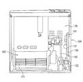
図3は、一般的なガスファンヒータの内部構造を示す概略正面図であり、ケーシング(104)内には、ガスバーナや送風ファン(121)が配設されている温風発生装置(102)と、温風発生装置(102)の各種動作やガス供給管(142)に介設されたバルブユニット(122)を制御するための制御回路を有する制御基板(130)が配設されている制御室(120)とが設けられている。 FIG. 3 is a schematic front view showing an internal structure of a general gas fan heater. A hot air generator (102) in which a gas burner and a blower fan (121) are disposed in a casing (104), and FIG. A control chamber in which a control board (130) having a control circuit for controlling various operations of the hot air generator (102) and a valve unit (122) interposed in the gas supply pipe (142) is disposed. (120).
この種の温風暖房機では、一般に、地震などによって温風暖房機が転倒した際に温風発生装置(102)の運転を禁止するため、ケーシング(104)の傾きを検知する安全装置として転倒スイッチ(101)が制御基板(130)上に設けられている。 In this type of hot air heater, in general, when the hot air heater is overturned due to an earthquake or the like, operation of the hot air generator (102) is prohibited, so it falls as a safety device that detects the inclination of the casing (104). A switch (101) is provided on the control board (130).
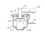
上記転倒スイッチ(101)としては、従来から機械接点式のものが汎用されており、この転倒スイッチ(101)の構造について図4を参照して説明すると、転倒スイッチ(101)は有底円筒形の金属製ハウジング(110)と、ハウジング(110)の開口部を閉塞する金属製の円形の蓋板(112)とを有する密封容器内に導電性の金属や合金からなる球体(111)が収容されており、蓋板(112)には導電性のリードピン(133)がガラス等の電気絶縁性充填材(113)により気密に絶縁固定されている。また、リードピン(133)の下端側にはリードピン(133)の先端を中心に複数の導電材料製の接点板(132)がほぼ同心円状に配設されてある。 As the fall switch (101), a mechanical contact type has been widely used. The structure of the fall switch (101) will be described with reference to FIG. 4. The fall switch (101) has a bottomed cylindrical shape. A spherical body (111) made of conductive metal or alloy is contained in a sealed container having a metal housing (110) and a metal circular lid (112) that closes the opening of the housing (110). In addition, a conductive lead pin (133) is hermetically insulated and fixed to the lid plate (112) by an electrically insulating filler (113) such as glass. A plurality of contact plates (132) made of a conductive material are arranged substantially concentrically around the tip of the lead pin (133) on the lower end side of the lead pin (133).
この転倒スイッチ(101)の動作について説明すると、球体(111)は、静止時にはハウジング(110)の底面の中央に設けられた凹部(110a)内に嵌まり込んでおり、この状態では球体(111)は接点板(132)とは接触しておらず、従って、リードピン(133)と蓋体(112)との間には電路は形成されない。 The operation of the overturn switch (101) will be described.The sphere (111) is fitted in a recess (110a) provided in the center of the bottom surface of the housing (110) when stationary, and in this state the sphere (111 ) Is not in contact with the contact plate (132), and therefore no electric circuit is formed between the lead pin (133) and the lid (112).
一方、地震やケーシング(104)に対する外部からの衝撃等により、ケーシング(104)が傾いた場合、球体(111)は凹部(110a)を飛び出て、ハウジング(110)内を転がると共に、接点板(132)に接触する。これにより、接点板(132)とハウジング(110)とが電気的に短絡し、リードピン(133)−接点板(132)−球体(111)−ハウジング(110)−蓋板(112)の経路で電路が形成されて、ラグターミナル(114)を介して信号が制御回路に出力され、制御回路が温風発生装置の運転を禁止する。 On the other hand, when the casing (104) tilts due to an earthquake or an external impact on the casing (104), the sphere (111) jumps out of the recess (110a) and rolls in the housing (110), and contacts ( 132). As a result, the contact plate (132) and the housing (110) are electrically short-circuited, and the path of the lead pin (133) -contact plate (132) -sphere (111) -housing (110) -lid plate (112) is used. An electric circuit is formed, and a signal is output to the control circuit via the lug terminal (114), and the control circuit prohibits the operation of the hot air generator.
ところで、温風暖房機には、操作確認や安全性確認のために、使用者が入力スイッチを操作した時や酸欠等の異常時に、報知音が発生するように圧電ブザーなどの報知器(131)が設けられる場合がある。このような報知器(131)は、図3に示すように、配線の容易性などを考慮して、転倒スイッチ(101)と同一の制御基板(130)上に設置されることが多い。 By the way, in the hot air heater, for operation confirmation and safety confirmation, an alarm device such as a piezoelectric buzzer (such as a piezoelectric buzzer) is generated so that a notification sound is generated when the user operates the input switch or when an abnormality such as lack of oxygen occurs. 131) may be provided. Such an alarm (131) is often installed on the same control board (130) as the overturn switch (101) in consideration of the ease of wiring, as shown in FIG.
しかしながら、このような同一の制御基板(130)上に転倒スイッチ(101)と報知器(131)とが設けられている場合、報知器(131)の振動が転倒スイッチ(101)のハウジング(110)に伝達されることとなる。そのため、球体(111)が自由状態で収容されている機械接点式の転倒スイッチ(101)では、ハウジング(110)の振動により球体(111)が凹部(110a)の周面に当たる場合がある。その結果、ケーシング(104)が傾いていないにも関わらず、温風装置の運転が禁止される誤動作が生じたり、報知音に転倒スイッチ(101)からの振動音が雑音として混ざり、報知音の音色が安定しなかったり、報知器(131)の故障が疑われてしまうという問題がある。 However, when the fall switch (101) and the alarm (131) are provided on the same control board (130), the vibration of the alarm (131) is caused by the housing (110 of the fall switch (101). ). Therefore, in the mechanical contact type inversion switch (101) in which the sphere (111) is accommodated in a free state, the sphere (111) may hit the peripheral surface of the recess (110a) due to vibration of the housing (110). As a result, although the casing (104) is not tilted, a malfunction that prohibits the operation of the hot air device occurs, or the alarm sound is mixed with the vibration sound from the overturn switch (101) as noise. There are problems that the timbre is not stable or that the alarm (131) is suspected to be faulty.
本発明は上記事情に鑑みてなされたもので、本発明の目的は、転倒時に運転を禁止させるための転倒スイッチと入力スイッチ等を操作したときの操作音を報知する報知器とが同一の制御基板上に設けられている温風暖房機において、ハウジングの傾斜を確実に検知できるとともに、報知器から雑音のない報知音を報知可能な温風暖房機を提供することにある。 The present invention has been made in view of the above circumstances, and an object of the present invention is to control the fall switch for prohibiting operation at the time of fall and the alarm for notifying operation sound when operating the input switch and the like. An object of the present invention is to provide a hot air heater that can reliably detect the inclination of the housing in the hot air heater provided on the substrate and can notify the alarm sound without noise from the alarm.
本発明は、ケーシング内部に、温風発生装置と、前記温風発生装置の運転を制御するための制御回路を有する制御基板とを備えた温風暖房機であって、
前記制御基板は、前記ケーシングの傾きを検知する加速度センサと、点火・消火や温度調節等の人為的な操作が各種操作スイッチで行なわれたことを音により報知する報知器とを同一面上に有しており、
前記制御回路は、前記加速度センサで検知されるケーシングの傾きが所定角度以上である場合、前記温風発生装置の運転を禁止する制御構成を有する、温風暖房機である。
The present invention is a hot air heater comprising a hot air generator inside a casing and a control board having a control circuit for controlling the operation of the hot air generator,
The control board has an acceleration sensor that detects the inclination of the casing and a notification device that informs by sound that artificial operations such as ignition / extinguishing and temperature adjustment have been performed with various operation switches. Have
The said control circuit is a warm air heater which has a control structure which prohibits the driving | operation of the said warm air generator, when the inclination of the casing detected by the said acceleration sensor is more than a predetermined angle.
加速度センサは、物体の動きや地震などの振動を検出できるほか、傾斜角度も検知することができる。このため、加速度センサを転倒スイッチとして利用し、ハウジングの傾きを検知して温風発生装置の運転を制御すれば、転倒スイッチと報知器とが同一の制御基板上に設けられていても、確実にケーシングの傾きを検知することができる。そして、上記加速度センサは、従来の機械接点式の転倒スイッチのように、ハウジング内に球体が移動可能に収納された構造でないから、報知器からの報知音の発生により制御基板を介して転倒スイッチに振動が伝わったとしても、加速度センサ自体から振動音が発生することがない。 The acceleration sensor can detect the movement of an object and vibration such as an earthquake, and can also detect an inclination angle. For this reason, if the acceleration sensor is used as a fall switch to detect the inclination of the housing and control the operation of the hot air generator, even if the fall switch and the alarm are provided on the same control board, it is ensured. In addition, the inclination of the casing can be detected. And since the said acceleration sensor is not the structure where the spherical body was movably accommodated in the housing like the conventional mechanical contact type fall switch, the fall switch via the control board by the generation of the alarm sound from the alarm Even if vibration is transmitted to the acceleration sensor, no vibration sound is generated from the acceleration sensor itself.
ガスファンヒータ等のような温風暖房機の転倒スイッチとして、加速度センサを採用したことにより、転倒スイッチと報知器とが同一の制御基板上に設けられていても、地震等によるハウジングの傾きを確実に検知して温風発生装置の運転を禁止することができる。また、転倒スイッチと報知器とが同一の制御基板上に設けられていても、転倒スイッチから振動音が発生することはない。これにより、報知音に振動音が雑音として混ざることがなく、報知音を常に安定した音色で発生させることができると共に、振動音の混入により報知器のスピーカの故障が疑われてしまうといった不都合を防止できる。 By adopting an acceleration sensor as a fall switch for hot air heaters such as gas fan heaters, even if the fall switch and alarm are provided on the same control board, the inclination of the housing due to an earthquake etc. It is possible to reliably detect the operation of the hot air generator. Further, even if the overturn switch and the alarm are provided on the same control board, no vibration noise is generated from the overturn switch. As a result, vibration sound is not mixed as noise with the notification sound, and the notification sound can always be generated with a stable tone, and the trouble of the speaker of the alarm device is suspected due to the mixing of vibration sound. Can be prevented.
以下に、本発明の実施形態をなす温風暖房機について、ガスファンヒータを例に挙げて、図面を参照しながら説明する。
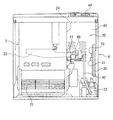
図1は、前面パネルを外した状態の温風暖房機の内部を示す概略正面図であり、ガスファンヒータの矩形のケーシング(4)は、その前面側を覆い且つ下方部に吹出口が形成されている前面パネルと、背面側を覆う背面パネル(43)とを備えている。ケーシング(4)の上面部には、点火・消火操作や設定温度の調節等の操作スイッチと、設定温度やタイマー等を表示する液晶表示部とからなる表示操作部(44)が設けられている。尚、図示しないが、ケーシング(4)からは電源コードとガスホースとが延長している。
Hereinafter, a hot air heater constituting an embodiment of the present invention will be described with reference to the drawings, taking a gas fan heater as an example.
FIG. 1 is a schematic front view showing the inside of the hot air heater with the front panel removed, and the rectangular casing (4) of the gas fan heater covers the front side and has a blower outlet formed in the lower part. And a back panel (43) covering the back side. On the upper surface of the casing (4), there is provided a display operation section (44) comprising operation switches for ignition / extinguishing operation and adjustment of set temperature, and a liquid crystal display section for displaying set temperature, timer, etc. . Although not shown, a power cord and a gas hose extend from the casing (4).
ケーシング(4)内には、ガスバーナ(23)及び送風ファン(21)を収納させた温風発生装置(2)が設置され、温風発生装置(2)の側方の制御室(20)には、ガス供給管(42)に介設されたバルブユニット(22)が設置されている。 In the casing (4), a hot air generator (2) containing a gas burner (23) and a blower fan (21) is installed, and is placed in a control chamber (20) on the side of the hot air generator (2). Is provided with a valve unit (22) interposed in the gas supply pipe (42).
制御室(20)側の温風発生装置(2)の側壁(24)には、ガスバーナ(23)の混合管部(41)が露出しており、混合管部(41)先端には吸入口(40)が設けられている。吸入口(40)には、ガスバーナ(23)に燃料ガスを供給するガス供給管(42)の下流端が挿入されてあり、吸入口(40)には、ガス供給管(42)の下流端から噴出する燃料ガス流のエジェクタ効果によって、ガス供給管(42)と吸入口(40)との隙間から一次空気が吸入され、混合管部(41)内にて燃料ガスと一次空気とが混合される。 The mixing tube portion (41) of the gas burner (23) is exposed on the side wall (24) of the hot air generator (2) on the control chamber (20) side, and the inlet is provided at the tip of the mixing tube portion (41). (40) is provided. A downstream end of a gas supply pipe (42) for supplying fuel gas to the gas burner (23) is inserted into the suction port (40), and a downstream end of the gas supply pipe (42) is inserted into the suction port (40). The primary air is sucked from the gap between the gas supply pipe (42) and the suction port (40) by the ejector effect of the fuel gas flow ejected from the fuel gas, and the fuel gas and the primary air are mixed in the mixing pipe part (41). Is done.
また、制御室(20)内におけるケーシング(4)の内壁の所定位置には、温風発生装置(2)の運転を制御するための制御回路を有する制御基板(30)が設置されている。そして、制御基板(30)の同一表面上には、圧電ブザーからなる報知器(31)と、転倒スイッチとしての加速度センサ(15)とが設置されている。 A control board (30) having a control circuit for controlling the operation of the hot air generator (2) is installed at a predetermined position on the inner wall of the casing (4) in the control room (20). On the same surface of the control board (30), an alarm (31) made of a piezoelectric buzzer and an acceleration sensor (15) as a fall switch are installed.
報知器(31)は、ガスバーナ(23)の点火・消火や室温の温度調節、タイマー設定等、人為的な操作により表示操作部(44)の各種操作スイッチが押されたとき、確実に入力されたことを音で報知する。また、報知器(31)は、各操作スイッチの入力時以外、例えば、酸欠時や、ケーシング(4)の傾きや転倒等の異常時、さらにケーシング(4)の移動時に電源コードやガスホースに引っ張りによるストレスが温風暖房機に加わったときにも、報知音が出力されるように設定されている。 The alarm (31) is surely input when various operation switches of the display operation unit (44) are pressed by human operation such as ignition / extinguishing of the gas burner (23), temperature adjustment of the room temperature, timer setting, etc. This is notified by sound. In addition, the alarm (31) is connected to the power cord or gas hose at the time of lack of oxygen, when there is an oxygen deficiency, when the casing (4) is tilted or overturned, or when the casing (4) is moved. The alarm sound is set to be output even when stress due to pulling is applied to the hot air heater.
加速度センサ(15)としては、例えば、MEMS技術によりシリコン・ウェハ上に機械的な機構と集積回路とが一体的に設けられている従来公知のものを用いることができる。本実施の形態において、加速度センサ(15)は、検出軸X軸が温風暖房機の前後方向に、検出軸Y軸が温風暖房機の左右方向に、検出軸Z軸が垂直方向にそれぞれ一致するように制御基板(30)上に配設されており、センサ自体の速度の変化から、その移動距離や、傾斜角度、衝撃の有無を検出することができる。 As the acceleration sensor (15), for example, a conventionally known sensor in which a mechanical mechanism and an integrated circuit are integrally provided on a silicon wafer by MEMS technology can be used. In the present embodiment, the acceleration sensor (15) has a detection axis X-axis in the front-rear direction of the hot air heater, a detection axis Y-axis in the left-right direction of the hot-air heater, and a detection axis Z-axis in the vertical direction. Arranged on the control board (30) so as to coincide with each other, it is possible to detect the movement distance, the inclination angle, and the presence or absence of an impact from the change in the speed of the sensor itself.
このような加速度センサ(15)は、機械接点式の転倒スイッチと異なり、球体の移動による傾きを検知するものでないから、報知器(31)からの振動が同一の制御基板(30)上に設けられている加速度センサ(15)に伝わったとしても、ケーシング(4)の傾きや電源コードなどが引っ張られた場合の衝撃が誤検知されることがなく、また、加速度センサ(15)自体から振動音が生じることはない。さらに、機械接点式の転倒スイッチでは、球体とハウジングの関係から転倒スイッチの取付場所や取付方向に制限があったが、加速度センサ(15)は任意の位置で任意の方向に設置することができるため、転倒スイッチの特性に起因して制御基板(30)の取付位置や取付方向が制限されることもない。 Such an acceleration sensor (15), unlike a mechanical contact type fall switch, does not detect tilt due to movement of a sphere, so vibration from the alarm (31) is provided on the same control board (30). Even if it is transmitted to the accelerometer (15), there is no false detection of the shock when the casing (4) is tilted or the power cord is pulled, and the acceleration sensor (15) itself vibrates. There is no sound. Furthermore, in the mechanical contact type overturn switch, the mounting position and direction of the overturn switch are limited due to the relationship between the sphere and the housing, but the acceleration sensor (15) can be installed in any direction at any position. Therefore, the mounting position and mounting direction of the control board (30) are not limited due to the characteristics of the overturn switch.
本実施の形態において、制御回路はマイクロコンピュータを含んで構成されており、図示しないが、操作スイッチの操作によってガスバーナ(23)の加熱量や送風ファン(21)の回転量を制御する運転制御部や、ケーシング(4)が傾いたり、電源コードやガスホースが引っ張られてストレスや衝撃を受けた場合に、加速度センサ(15)からの信号に基づき、温風発生装置(2)の運転を禁止し、報知器(31)から所定の警告を報知する運転禁止部などを制御構成として含んでいる。 In the present embodiment, the control circuit is configured to include a microcomputer, and although not shown, an operation control unit that controls the heating amount of the gas burner (23) and the rotation amount of the blower fan (21) by operating the operation switch. If the casing (4) is tilted or the power cord or gas hose is pulled and subjected to stress or impact, the operation of the hot air generator (2) is prohibited based on the signal from the acceleration sensor (15). In addition, an operation prohibiting unit for notifying a predetermined warning from the alarm (31) is included as a control configuration.
次に、本実施の形態の温風暖房機の動作について図2に示すフローチャートを参照して説明する。
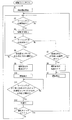
使用者が表示操作部(44)の運転スイッチをONにすると、ステップS1で、電源がONされて、送風ファン(21)及びバルブユニット(22)がON状態となり、ガスがガス供給管(42)を介してガスバーナ(23)に供給されると同時に点火されて、燃焼運転が開始される。そして、温風発生装置(2)内で生成される温風が送風ファン(21)からケーシング(4)の外部へ放出される。このとき、使用者が、温度調節スイッチや風量スイッチを操作すると、報知器(31)から報知音が発生するが、本実施の形態の温風暖房機では、転倒スイッチとして報知器(31)の振動による影響を受けない加速度センサ(15)が用いられているため、ケーシング(4)の傾きなどが誤検知されることなく、また報知器(31)から出力される報知音に振動音による「にごり」が生じることもない。
Next, the operation of the hot air heater of the present embodiment will be described with reference to the flowchart shown in FIG.
When the user turns on the operation switch of the display operation unit (44), the power is turned on in step S1, the blower fan (21) and the valve unit (22) are turned on, and the gas is supplied to the gas supply pipe (42 ) And is simultaneously ignited to start the combustion operation. Then, the warm air generated in the warm air generator (2) is discharged from the blower fan (21) to the outside of the casing (4). At this time, when the user operates the temperature adjustment switch or the air volume switch, a notification sound is generated from the alarm (31) .However, in the hot air heater of the present embodiment, the alarm (31) of the alarm (31) is used as a fall switch. Since the acceleration sensor (15) that is not affected by vibration is used, the inclination of the casing (4) is not erroneously detected, and the notification sound output from the alarm (31) “Nigori” does not occur.
燃焼運転中にケーシング(4)が動いた場合、ステップS2にて、温風発生装置(2)内の制御基板(30)に設けられている加速度センサ(15)がケーシング(4)の移動を検知すると共に、ステップS3にて、その移動方向を検知する。 If the casing (4) moves during the combustion operation, the acceleration sensor (15) provided on the control board (30) in the hot air generator (2) moves the casing (4) in step S2. At the same time, the moving direction is detected in step S3.
そして、さらに続くステップS4にて、ケーシング(4)が傾斜したかどうかを加速度センサ(15)が検知し、傾斜が検出されない場合(ステップS4でNo)は、ステップS5に進んで、ステップS3で検出した移動方向と逆方向に引っ張られる衝撃の有無が判定される。例えば、ケーシング(4)を移動させる際に、電源やガスコンセントに接続されたままの電源コードやガスホースが引っ張られてストレスがかかった場合に、ステップS5にて、Yesと判定されることとなる。すると、次のステップS6にて、加速度センサ(15)と共に制御基板(30)の同一面上に取り付けられている報知器(31)から報知音が出力されて、電源コード又はガスホースにストレスがかかっていることを報知すると共に、電源がOFFとなり、ステップS7にて、温風発生装置(2)の運転が禁止される。 In step S4, the acceleration sensor (15) detects whether the casing (4) is tilted. If no tilt is detected (No in step S4), the process proceeds to step S5, and in step S3. It is determined whether or not there is an impact pulled in a direction opposite to the detected moving direction. For example, when the casing (4) is moved and the power cord or gas hose connected to the power source or the gas outlet is pulled and stressed, it is determined as Yes in step S5. . Then, in the next step S6, an alarm sound is output from the alarm (31) mounted on the same surface of the control board (30) together with the acceleration sensor (15), and the power cord or gas hose is stressed. And the power is turned off, and the operation of the hot air generator (2) is prohibited in step S7.
先のステップS4にて、ケーシング(4)が傾斜していると判定されると、ステップS8にて、加速度センサ(15)から出力される値が所定の閾値A以上であるか否かが判定され、閾値A以上であると判定されると(ステップS8でYes)、ステップS9にて、報知器(31)から報知音を出力して運転の継続の危険性を警告すると同時に、電源がOFFされ、ステップS10にて、運転が禁止される。 If it is determined in step S4 that the casing (4) is inclined, it is determined in step S8 whether or not the value output from the acceleration sensor (15) is equal to or greater than a predetermined threshold A. If it is determined that the value is equal to or greater than the threshold value A (Yes in step S8), in step S9, a notification sound is output from the alarm device (31) to warn of the danger of continued operation, and at the same time, the power is turned off. In step S10, driving is prohibited.
その後、転倒或いは傾斜状態にあったケーシング(4)が正常姿勢に復帰させられることにより、ステップ11にて、加速度センサ(15)から出力される値が、復帰時の所定の閾値B以下であることが判定されると、ステップ12にて、暫く待機した後、ステップ13にて、運転スイッチがOFFされたかどうかが判定され、運転スイッチが人為的にOFF操作された場合は、ステップS7にて、報知音が出力された後、運転が禁止される。
Thereafter, the casing (4) that has fallen or tilted is returned to the normal posture, so that the value output from the acceleration sensor (15) in step 11 is equal to or less than the predetermined threshold B at the time of return. In step 12, after waiting for a while in step 12, it is determined in
ステップ13にて、運転スイッチがOFFされないと判定された場合は、ステップS1に戻って電源がONとなり、ガスファンヒータの運転が再開する。
If it is determined in
尚、上記実施の形態では、温風暖房機として、ガスファンヒータを採用したが、本発明は石油ファンヒータや電気式のものにも採用可能である。 In the above embodiment, the gas fan heater is used as the hot air heater, but the present invention can also be applied to an oil fan heater or an electric heater.
(2) ・・・・温風発生装置
(4) ・・・・ケーシング
(15)・・・・加速度センサ
(30)・・・・制御基板
(31)・・・・報知器
(2) ・ ・ ・ ・ Hot air generator
(4) ・ ・ ・ ・ Case
(15) ... Acceleration sensor
(30) ... Control board
(31) ... Alarm
Claims (1)
前記制御基板は、前記ケーシングの傾きを検知する加速度センサと、点火・消火や温度調節等の人為的な操作が各種操作スイッチで行なわれたことを音により報知する報知器とを同一面上に有しており、
前記制御回路は、前記加速度センサで検知されるケーシングの傾きが所定角度以上である場合、前記温風発生装置の運転を禁止する制御構成を有する温風暖房機。 A hot air heater provided with a hot air generator inside a casing and a control board having a control circuit for controlling the operation of the hot air generator,
The control board has an acceleration sensor that detects the inclination of the casing and a notification device that informs by sound that artificial operations such as ignition / extinguishing and temperature adjustment have been performed with various operation switches. Have
The said control circuit is a warm air heater which has a control structure which prohibits the driving | operation of the said warm air generator, when the inclination of the casing detected by the said acceleration sensor is more than a predetermined angle.
Priority Applications (1)
| Application Number | Priority Date | Filing Date | Title |
|---|---|---|---|
| JP2010266978A JP5592240B2 (en) | 2010-11-30 | 2010-11-30 | Hot air heater |
Applications Claiming Priority (1)
| Application Number | Priority Date | Filing Date | Title |
|---|---|---|---|
| JP2010266978A JP5592240B2 (en) | 2010-11-30 | 2010-11-30 | Hot air heater |
Publications (2)
| Publication Number | Publication Date |
|---|---|
| JP2012117728A true JP2012117728A (en) | 2012-06-21 |
| JP5592240B2 JP5592240B2 (en) | 2014-09-17 |
Family
ID=46500778
Family Applications (1)
| Application Number | Title | Priority Date | Filing Date |
|---|---|---|---|
| JP2010266978A Expired - Fee Related JP5592240B2 (en) | 2010-11-30 | 2010-11-30 | Hot air heater |
Country Status (1)
| Country | Link |
|---|---|
| JP (1) | JP5592240B2 (en) |
Cited By (2)
| Publication number | Priority date | Publication date | Assignee | Title |
|---|---|---|---|---|
| JP2015215658A (en) * | 2014-05-08 | 2015-12-03 | アズビル株式会社 | Removal detection device and removal detection method for authentication device |
| DE102016210418A1 (en) * | 2016-06-13 | 2017-12-14 | Robert Bosch Gmbh | Method and control unit for detecting fault conditions in a heating system and / or in an air conditioning system and a heating system and / or an air conditioning system |
Citations (6)
| Publication number | Priority date | Publication date | Assignee | Title |
|---|---|---|---|---|
| JPS63185055U (en) * | 1987-05-21 | 1988-11-28 | ||
| JP2001099856A (en) * | 1999-09-28 | 2001-04-13 | Ubukata Industries Co Ltd | Conductive liquid and liquid acceleration sensor using the same |
| JP2002340336A (en) * | 2001-05-18 | 2002-11-27 | Corona Corp | Combustion apparatus |
| JP2004020518A (en) * | 2002-06-20 | 2004-01-22 | Ubukata Industries Co Ltd | Electrostatic capacity type liquid sensor |
| JP2008035962A (en) * | 2006-08-02 | 2008-02-21 | Nintendo Co Ltd | Game apparatus with general-purpose remote control function |
| JP2010043929A (en) * | 2008-08-12 | 2010-02-25 | Yamaha Corp | Motion sensor |
-
2010
- 2010-11-30 JP JP2010266978A patent/JP5592240B2/en not_active Expired - Fee Related
Patent Citations (6)
| Publication number | Priority date | Publication date | Assignee | Title |
|---|---|---|---|---|
| JPS63185055U (en) * | 1987-05-21 | 1988-11-28 | ||
| JP2001099856A (en) * | 1999-09-28 | 2001-04-13 | Ubukata Industries Co Ltd | Conductive liquid and liquid acceleration sensor using the same |
| JP2002340336A (en) * | 2001-05-18 | 2002-11-27 | Corona Corp | Combustion apparatus |
| JP2004020518A (en) * | 2002-06-20 | 2004-01-22 | Ubukata Industries Co Ltd | Electrostatic capacity type liquid sensor |
| JP2008035962A (en) * | 2006-08-02 | 2008-02-21 | Nintendo Co Ltd | Game apparatus with general-purpose remote control function |
| JP2010043929A (en) * | 2008-08-12 | 2010-02-25 | Yamaha Corp | Motion sensor |
Cited By (2)
| Publication number | Priority date | Publication date | Assignee | Title |
|---|---|---|---|---|
| JP2015215658A (en) * | 2014-05-08 | 2015-12-03 | アズビル株式会社 | Removal detection device and removal detection method for authentication device |
| DE102016210418A1 (en) * | 2016-06-13 | 2017-12-14 | Robert Bosch Gmbh | Method and control unit for detecting fault conditions in a heating system and / or in an air conditioning system and a heating system and / or an air conditioning system |
Also Published As
| Publication number | Publication date |
|---|---|
| JP5592240B2 (en) | 2014-09-17 |
Similar Documents
| Publication | Publication Date | Title |
|---|---|---|
| JP5478026B2 (en) | Fire alarm | |
| KR101853919B1 (en) | a Multipurpose fire alarm | |
| JP2009142419A (en) | Smoke fire extinguishing device | |
| JP5378166B2 (en) | Temperature and humidity detector | |
| JP5592240B2 (en) | Hot air heater | |
| JP5443332B2 (en) | Gas cooker | |
| JP2019164679A (en) | Thermal alarm | |
| TWM335683U (en) | Sensing device for motorcycle inclination | |
| JP5666178B2 (en) | Overheat detection adapter and oxygen concentrator having overheat detection adapter | |
| JP2019212269A5 (en) | sensor | |
| WO2012001951A1 (en) | Overheating sensor adapter, overheating sensor adapter unit, and oxygen concentrator unit comprising overheating sensor adapter | |
| JP2019132564A (en) | Cooking stove | |
| JP2008185312A (en) | Heater with abnormality detecting function | |
| JP6715750B2 (en) | Equipment with seismic function | |
| JP6802080B2 (en) | Stationary heating system | |
| JP5481209B2 (en) | Battery device | |
| JP2021092351A (en) | Combustion device | |
| JP2017188062A (en) | Heating tester | |
| JPH09159163A (en) | Combustion device | |
| JPH0960872A (en) | Combustion heating device | |
| JP2008228704A (en) | Underwater heater | |
| JPH10201633A (en) | Inversion accident prevention device for bread making machine | |
| JP2001235147A (en) | Combustion heater | |
| JP2023009946A (en) | Burning device | |
| JP2902753B2 (en) | Humidifier |
Legal Events
| Date | Code | Title | Description |
|---|---|---|---|
| A621 | Written request for application examination |
Free format text: JAPANESE INTERMEDIATE CODE: A621 Effective date: 20120906 |
|
| A977 | Report on retrieval |
Free format text: JAPANESE INTERMEDIATE CODE: A971007 Effective date: 20130913 |
|
| A131 | Notification of reasons for refusal |
Free format text: JAPANESE INTERMEDIATE CODE: A131 Effective date: 20131008 |
|
| A521 | Request for written amendment filed |
Free format text: JAPANESE INTERMEDIATE CODE: A523 Effective date: 20131205 |
|
| A131 | Notification of reasons for refusal |
Free format text: JAPANESE INTERMEDIATE CODE: A131 Effective date: 20140204 |
|
| A521 | Request for written amendment filed |
Free format text: JAPANESE INTERMEDIATE CODE: A523 Effective date: 20140402 |
|
| TRDD | Decision of grant or rejection written | ||
| A01 | Written decision to grant a patent or to grant a registration (utility model) |
Free format text: JAPANESE INTERMEDIATE CODE: A01 Effective date: 20140708 |
|
| A61 | First payment of annual fees (during grant procedure) |
Free format text: JAPANESE INTERMEDIATE CODE: A61 Effective date: 20140731 |
|
| R150 | Certificate of patent or registration of utility model |
Ref document number: 5592240 Country of ref document: JP Free format text: JAPANESE INTERMEDIATE CODE: R150 |
|
| R250 | Receipt of annual fees |
Free format text: JAPANESE INTERMEDIATE CODE: R250 |
|
| R250 | Receipt of annual fees |
Free format text: JAPANESE INTERMEDIATE CODE: R250 |
|
| R250 | Receipt of annual fees |
Free format text: JAPANESE INTERMEDIATE CODE: R250 |
|
| R250 | Receipt of annual fees |
Free format text: JAPANESE INTERMEDIATE CODE: R250 |
|
| R250 | Receipt of annual fees |
Free format text: JAPANESE INTERMEDIATE CODE: R250 |
|
| R250 | Receipt of annual fees |
Free format text: JAPANESE INTERMEDIATE CODE: R250 |
|
| LAPS | Cancellation because of no payment of annual fees |