JP2012117482A - Heat-shielding film and method of forming the same - Google Patents
Heat-shielding film and method of forming the same Download PDFInfo
- Publication number
- JP2012117482A JP2012117482A JP2010269567A JP2010269567A JP2012117482A JP 2012117482 A JP2012117482 A JP 2012117482A JP 2010269567 A JP2010269567 A JP 2010269567A JP 2010269567 A JP2010269567 A JP 2010269567A JP 2012117482 A JP2012117482 A JP 2012117482A
- Authority
- JP
- Japan
- Prior art keywords
- hollow particles
- thermal barrier
- barrier film
- wall surface
- metal
- Prior art date
- Legal status (The legal status is an assumption and is not a legal conclusion. Google has not performed a legal analysis and makes no representation as to the accuracy of the status listed.)
- Granted
Links
Images


Classifications
-
- F—MECHANICAL ENGINEERING; LIGHTING; HEATING; WEAPONS; BLASTING
- F02—COMBUSTION ENGINES; HOT-GAS OR COMBUSTION-PRODUCT ENGINE PLANTS
- F02B—INTERNAL-COMBUSTION PISTON ENGINES; COMBUSTION ENGINES IN GENERAL
- F02B77/00—Component parts, details or accessories, not otherwise provided for
- F02B77/11—Thermal or acoustic insulation
-
- F—MECHANICAL ENGINEERING; LIGHTING; HEATING; WEAPONS; BLASTING
- F02—COMBUSTION ENGINES; HOT-GAS OR COMBUSTION-PRODUCT ENGINE PLANTS
- F02B—INTERNAL-COMBUSTION PISTON ENGINES; COMBUSTION ENGINES IN GENERAL
- F02B77/00—Component parts, details or accessories, not otherwise provided for
- F02B77/02—Surface coverings of combustion-gas-swept parts
-
- F—MECHANICAL ENGINEERING; LIGHTING; HEATING; WEAPONS; BLASTING
- F05—INDEXING SCHEMES RELATING TO ENGINES OR PUMPS IN VARIOUS SUBCLASSES OF CLASSES F01-F04
- F05C—INDEXING SCHEME RELATING TO MATERIALS, MATERIAL PROPERTIES OR MATERIAL CHARACTERISTICS FOR MACHINES, ENGINES OR PUMPS OTHER THAN NON-POSITIVE-DISPLACEMENT MACHINES OR ENGINES
- F05C2203/00—Non-metallic inorganic materials
- F05C2203/08—Ceramics; Oxides
- F05C2203/0865—Oxide ceramics
- F05C2203/0878—Aluminium titanate
-
- F—MECHANICAL ENGINEERING; LIGHTING; HEATING; WEAPONS; BLASTING
- F05—INDEXING SCHEMES RELATING TO ENGINES OR PUMPS IN VARIOUS SUBCLASSES OF CLASSES F01-F04
- F05C—INDEXING SCHEME RELATING TO MATERIALS, MATERIAL PROPERTIES OR MATERIAL CHARACTERISTICS FOR MACHINES, ENGINES OR PUMPS OTHER THAN NON-POSITIVE-DISPLACEMENT MACHINES OR ENGINES
- F05C2203/00—Non-metallic inorganic materials
- F05C2203/08—Ceramics; Oxides
- F05C2203/0865—Oxide ceramics
- F05C2203/0886—Silica
-
- F—MECHANICAL ENGINEERING; LIGHTING; HEATING; WEAPONS; BLASTING
- F05—INDEXING SCHEMES RELATING TO ENGINES OR PUMPS IN VARIOUS SUBCLASSES OF CLASSES F01-F04
- F05C—INDEXING SCHEME RELATING TO MATERIALS, MATERIAL PROPERTIES OR MATERIAL CHARACTERISTICS FOR MACHINES, ENGINES OR PUMPS OTHER THAN NON-POSITIVE-DISPLACEMENT MACHINES OR ENGINES
- F05C2251/00—Material properties
- F05C2251/04—Thermal properties
- F05C2251/048—Heat transfer
-
- Y—GENERAL TAGGING OF NEW TECHNOLOGICAL DEVELOPMENTS; GENERAL TAGGING OF CROSS-SECTIONAL TECHNOLOGIES SPANNING OVER SEVERAL SECTIONS OF THE IPC; TECHNICAL SUBJECTS COVERED BY FORMER USPC CROSS-REFERENCE ART COLLECTIONS [XRACs] AND DIGESTS
- Y10—TECHNICAL SUBJECTS COVERED BY FORMER USPC
- Y10T—TECHNICAL SUBJECTS COVERED BY FORMER US CLASSIFICATION
- Y10T29/00—Metal working
- Y10T29/49—Method of mechanical manufacture
- Y10T29/49229—Prime mover or fluid pump making
- Y10T29/49231—I.C. [internal combustion] engine making
Landscapes
- Engineering & Computer Science (AREA)
- Chemical & Material Sciences (AREA)
- Combustion & Propulsion (AREA)
- Mechanical Engineering (AREA)
- General Engineering & Computer Science (AREA)
- Physics & Mathematics (AREA)
- Acoustics & Sound (AREA)
- Cylinder Crankcases Of Internal Combustion Engines (AREA)
- Laminated Bodies (AREA)
- Other Surface Treatments For Metallic Materials (AREA)
- Finishing Walls (AREA)
Abstract
Description
本発明は、金属母材の壁面に形成される遮熱膜とその形成方法に係り、たとえば内燃機関の燃焼室に臨む壁面の一部もしくは全部に形成される遮熱膜とその形成方法に関するものである。 The present invention relates to a heat shield film formed on a wall surface of a metal base material and a method for forming the same, for example, a heat shield film formed on part or all of a wall surface facing a combustion chamber of an internal combustion engine and a method for forming the same. It is.
ガソリンエンジンやディーゼルエンジン等の内燃機関は、主にエンジンブロックとシリンダヘッドから構成されており、その燃焼室は、シリンダブロックのボア面と、このボアに組み込まれたピストン頂面と、シリンダヘッドの底面と、シリンダヘッド内に配設された吸入および排気バルブの頂面から画成されている。昨今の内燃機関に要求される高出力化にともなってその冷却損失を低減することが重要になってくるが、この冷却損失を低減する方策の一つとして、燃焼室の内壁にセラミックスからなる遮熱膜を形成する方法を挙げることができる。 An internal combustion engine such as a gasoline engine or a diesel engine is mainly composed of an engine block and a cylinder head, and its combustion chamber has a bore surface of the cylinder block, a piston top surface incorporated in the bore, and a cylinder head. It is defined by a bottom surface and a top surface of an intake and exhaust valve disposed in the cylinder head. It is important to reduce the cooling loss with the increase in output required for recent internal combustion engines. As one of the measures to reduce this cooling loss, the inner wall of the combustion chamber is shielded from ceramics. A method of forming a hot film can be mentioned.
しかし、上記するセラミックスは一般に低い熱伝導率を有し、かつ高い熱容量を有することから、定常的な表面温度上昇による吸気効率の低下やノッキング(燃焼室内に熱が篭ることに起因する異常燃焼)が発生するために燃焼室の内壁への被膜素材として普及していないのが現状である。 However, the ceramics mentioned above generally have a low thermal conductivity and a high heat capacity, so that the intake efficiency decreases and knocks due to a steady increase in surface temperature (knocking abnormal combustion due to heat generated in the combustion chamber). As a result, the present situation is that it is not widely used as a coating material on the inner wall of the combustion chamber.
このことから、燃焼室の壁面に形成される遮熱膜は、耐熱性と断熱性は勿論のこと、低熱伝導率と低熱容量の素材から形成されるのが望ましい。さらに、この低熱伝導率および低熱容量であることに加えて、燃焼室内での燃焼時の爆発圧や噴射圧、熱膨張と熱収縮の繰り返しに追随できる変形性能を有する被膜であること、およびシリンダブロック等の母材との間で熱変形量に起因する界面剥離の生じ難い被膜であることが望ましい。 For this reason, it is desirable that the thermal barrier film formed on the wall surface of the combustion chamber is made of a material having low heat conductivity and low heat capacity as well as heat resistance and heat insulation. Further, in addition to the low thermal conductivity and the low heat capacity, the coating has a deformation performance capable of following the explosion pressure and injection pressure during combustion in the combustion chamber, and repeated thermal expansion and contraction, and the cylinder. It is desirable that the coating is less likely to cause interface peeling due to the amount of thermal deformation with a base material such as a block.
ここで、従来の公開技術に目を転じるに、特許文献1,2には、内燃機関の燃焼室を形成する母材よりも低い熱伝導率を有し、かつ母材と同等もしくは母材よりも低い熱容量を有する材料の内部に気泡が形成された断熱用薄膜を有する内燃機関が開示されている。
Here, turning to the conventional published technology,
上記する特許文献1,2には内燃機関の燃焼室の内壁に低熱伝導率で低熱容量の被膜を形成する技術が開示されており、上記するように性能に優れた断熱膜(遮熱膜)となり得る。
しかし、これらの断熱膜構造は、セラミックス等からなる断熱材の内部に気泡が形成されたものであることから、断熱膜に良好な変形性能を期待し難く、この断熱膜が燃焼室内での熱膨張と熱収縮の繰り返し応力を受ける過程で熱疲労による損傷が齎され、さらには、アルミ母材の基材との間で熱変形差が大きくなり易く、断熱膜と基材の界面で剥離が生じ易いという課題が生じ得る。 However, since these heat insulating film structures are formed by bubbles inside a heat insulating material made of ceramics or the like, it is difficult to expect good deformation performance of the heat insulating film. Damage due to thermal fatigue is prone to occur in the process of repeated stress of expansion and contraction, and furthermore, the thermal deformation difference between the aluminum base material and the base material tends to increase, and peeling occurs at the interface between the heat insulating film and the base material. The problem of easily occurring can occur.
本発明は上記する問題に鑑みてなされたものであり、低熱伝導率かつ低熱容量であって、しかも、熱膨張と熱収縮の繰り返しに追随できる変形性能を有するとともに、シリンダブロック等の金属母材の壁面との間で熱変形差に起因する界面剥離の生じ難い遮熱膜と、この遮熱膜を壁面に形成する方法を提供することを目的とする。 The present invention has been made in view of the above problems, has a low thermal conductivity and a low heat capacity, and has a deformability capable of following repeated thermal expansion and contraction, and a metal base material such as a cylinder block. It is an object of the present invention to provide a thermal barrier film that hardly causes interfacial delamination due to a thermal deformation difference between the thermal barrier film and a method of forming the thermal barrier film on the wall surface.
前記目的を達成すべく、本発明による遮熱膜は、金属母材の壁面に形成される遮熱膜であって、複数のセラミックス中空粒子が金属相と点接合することで相互に接合されて前記遮熱膜を形成しており、前記遮熱膜を形成するセラミックス中空粒子と前記壁面もそれぞれが金属相と点接合することで相互に接合されているものである。 In order to achieve the above-mentioned object, the thermal barrier film according to the present invention is a thermal barrier film formed on the wall surface of a metal base material, and a plurality of ceramic hollow particles are bonded to each other by point bonding with a metal phase. The thermal barrier film is formed, and the ceramic hollow particles forming the thermal barrier film and the wall surface are also bonded to each other by spot bonding with the metal phase.
本発明の遮熱膜が形成される壁面の母材金属は、たとえばアルミニウムや、鋼、チタン、ニッケル、銅やそれらの合金からなり、この壁面用途としては、内燃機関の燃焼室に臨む壁面のほか、車両の吸排気ラインを構成する壁面、タービンブレードを構成する壁面、内燃機関や家屋、スペースシャトル等を収容するハウジングの外壁など、低熱伝導率と低熱容量が要求される様々な用途壁面を挙げることができる。そして、この遮熱膜が内燃機関に適用される場合において、この内燃機関はガソリンエンジンやディーゼルエンジンのいずれを対象としたものであってもよいし、さらにこの遮熱膜は、内燃機関の燃焼室を構成するシリンダブロックのボア面、このボアに組み込まれたピストン頂面、シリンダヘッドの底面、シリンダヘッド内に配設された吸入および排気バルブの頂面のすべての壁面に適用されてもよいし、そのうちのいずれか一つもしくは複数に適用されてもよい。 The base metal of the wall surface on which the thermal barrier film of the present invention is formed is made of, for example, aluminum, steel, titanium, nickel, copper, or an alloy thereof. As the wall surface application, the wall surface metal facing the combustion chamber of the internal combustion engine is used. In addition, various wall surfaces for which low thermal conductivity and low heat capacity are required, such as wall surfaces that constitute the intake and exhaust lines of vehicles, wall surfaces that constitute turbine blades, outer walls of housings that house internal combustion engines, houses, space shuttles, etc. Can be mentioned. And when this thermal barrier film is applied to an internal combustion engine, this internal combustion engine may be intended for either a gasoline engine or a diesel engine. It may be applied to all the wall surfaces of the bore surface of the cylinder block constituting the chamber, the top surface of the piston incorporated in the bore, the bottom surface of the cylinder head, and the top surface of the intake and exhaust valves disposed in the cylinder head. However, it may be applied to any one or more of them.
また、セラミックス中空粒子としては、アルミナ中空粒子やシリカ中空粒子、アルミナとシリカの複合材(双方の粒子の結合材)からなる中空粒子などを挙げることができる。さらに、この遮熱膜は、中空粒子同士が金属相を介して層状に形成されるものであり、この1層の厚みが中空粒子の平均粒径で規定される場合に、複数の中空粒子からなる1層の遮熱膜であってもよいし、2層以上からなる遮熱膜(各層を構成する中空粒子の平均粒径の合計が遮熱膜の厚みとなる)であってもよい。 Further, examples of the ceramic hollow particles include alumina hollow particles, silica hollow particles, and hollow particles made of a composite material of alumina and silica (a binder of both particles). Furthermore, this heat-shielding film is formed by forming a layer of hollow particles with each other through a metal phase, and when the thickness of this one layer is defined by the average particle size of the hollow particles, The heat-shielding film | membrane which consists of two layers or more (The sum total of the average particle diameter of the hollow particle which comprises each layer becomes thickness of a heat-shielding film | membrane) may be sufficient.
また、使用されるセラミックス中空粒子としては、1種類の平均粒径のセラミックス中空粒子を使用して遮熱膜を形成してもよいし、2以上の平均粒径の異なるセラミックス中空粒子を使用して遮熱膜を形成してもよい。さらに後者の実施の形態においては、相対的に大径のセラミックス中空粒子からなる層が壁面に直接接合される形態であってもよいし、逆に相対的に小径のセラミックス中空粒子からなる層が壁面に直接接合される形態であってもよい。 Further, as the ceramic hollow particles to be used, a thermal barrier film may be formed using ceramic hollow particles having one type of average particle diameter, or two or more ceramic hollow particles having different average particle diameters may be used. A thermal barrier film may be formed. Further, in the latter embodiment, the layer composed of relatively large-diameter ceramic hollow particles may be directly bonded to the wall surface, or conversely, the layer composed of relatively small-diameter ceramic hollow particles The form directly joined to a wall surface may be sufficient.
ここで、「複数のセラミックス中空粒子が金属相と点接合する」とは、セラミックス中空粒子同士を中空粒子の粒径よりも幅の狭い金属相で接合することを意味している。これは、たとえば金属粒を溶解させ、次いで焼結させることで溶融金属がセラミックス中空粒子間で毛細管現象によって縮まりながらセラミックス中空粒子に対して相対的に小さな相をなして周囲のセラミックス中空粒子と接合し、この際にセラミックス中空粒子が相対的に幅狭な金属相と接合(点接合)することになる。 Here, “a plurality of ceramic hollow particles are spot-bonded to the metal phase” means that the ceramic hollow particles are bonded to each other by a metal phase having a width smaller than the particle diameter of the hollow particles. This is because, for example, by melting metal particles and then sintering, the molten metal shrinks between the ceramic hollow particles by capillary action, forming a relatively small phase with respect to the ceramic hollow particles and joining with the surrounding ceramic hollow particles At this time, the ceramic hollow particles are joined (point joined) to a relatively narrow metal phase.
この金属相は、銀、銅、金のいずれか一種のナノ粒子が溶解され、次いで焼結されて形成されてなるものが好ましい。 The metal phase is preferably formed by dissolving nanoparticles of any one of silver, copper, and gold and then sintering.
金属粒の溶解に際しては、その粒径が小さくなるほど低温度でそれを溶解できること(たとえば銀の場合には、300nm程度のナノ粒子とすることで本来の融点:1000℃程度のものを500℃程度の比較的低温で溶解することができる)と、逆に小さすぎてはナノ粒子自体の製造困難性を来たすことなどから、たとえば数十nm〜数百nm程度の範囲の平均粒径の金属粒を使用するのが好ましい。そして、上で挙げた金属素材は、ナノ粒子を形成できることと酸化され難いことからその適用が好ましいと言える。 When the metal particles are dissolved, the smaller the particle size, the lower the temperature of the metal particles can be dissolved (for example, in the case of silver, the original melting point: about 500 ° C. is about 500 ° C. by using nanoparticles of about 300 nm) On the other hand, if the particle size is too small, the nanoparticles themselves are difficult to produce. For example, metal particles having an average particle size in the range of several tens to several hundreds of nanometers Is preferably used. And it can be said that the metal materials mentioned above are preferable to be applied because they can form nanoparticles and are not easily oxidized.
上記する本発明の遮熱膜によれば、これがセラミックス中空粒子からなる薄膜であることから低熱伝導率かつ低熱容量の遮熱膜となる。さらに、セラミックス中空粒子に比して相対的に小さな金属相でセラミックス中空粒子同士が点接合されていることにより、その膜構造は変形性能(可撓性)に優れた構造となる。 According to the heat shield film of the present invention described above, since this is a thin film made of ceramic hollow particles, it becomes a heat shield film with low thermal conductivity and low heat capacity. Furthermore, since the ceramic hollow particles are spot-bonded with a relatively small metal phase compared to the ceramic hollow particles, the film structure has a structure excellent in deformation performance (flexibility).
この膜構造に起因する変形性能に関しては、上記する特許文献1,2で開示されるセラミックス等からなる断熱材の内部に気泡が形成された断熱膜と構造比較すると理解が容易となる。すなわち、特許文献1,2で開示されるセラミックス膜の場合にはその内部構造が当該セラミックスによって剛なブロック構造を形成している。このため、この断熱膜に対して比較的低い外圧が作用した場合にはそのブロック構造を保持できるものの、断熱膜が変形されるような比較的高い外圧が作用した場合には変形性能が低いために膜内部に亀裂が生じ易くなってしまう。
The deformation performance resulting from this film structure can be easily understood by comparing the structure with the heat insulating film in which bubbles are formed inside the heat insulating material made of ceramics and the like disclosed in
さらに、この断熱膜が形成される金属母材からなる壁面は金属ゆえに大きく熱膨張や熱収縮することになるが、この壁面の熱変形の際に、変形性能の低い断熱膜ではこの壁面の熱変形に追随することができず、壁面と断熱膜の間の界面で剥離が生じ易くなり、接着性の低下に起因して耐久性の低い断熱膜構造となってしまう。 Furthermore, the wall made of a metal base material on which the heat insulating film is formed is greatly expanded and contracted due to the metal. It cannot follow the deformation, and peeling easily occurs at the interface between the wall surface and the heat insulating film, resulting in a heat insulating film structure with low durability due to a decrease in adhesiveness.
これに対し、本発明の遮熱膜では、セラミックス中空粒子同士が金属相で点接合されていることから、セラミックス中空粒子と金属相が強固に点接合されながら、この点接合を形成する金属相自体の変形性能が高いことに加えて、遮熱膜全体としての構造も変形性能に富む柔な網構造を形成している。そのため、遮熱膜に対してこれを変形させるだけの高い外圧が作用した場合でも容易に変形してその内部に亀裂等が生じることもないし、金属母材の壁面の大きな熱変形にも容易に追随できることから界面剥離の問題も生じ難く、耐久性の高い壁面と遮熱膜とからなる遮熱膜構造を形成できるのである。 On the other hand, in the thermal barrier film of the present invention, since the ceramic hollow particles are point-bonded with each other in the metal phase, the metal phase that forms this point bond while the ceramic hollow particles and the metal phase are strongly point-bonded. In addition to its high deformation performance, the overall structure of the heat-shielding film also forms a flexible network structure rich in deformation performance. For this reason, even when a high external pressure is applied to the heat shield film, it is not easily deformed to cause cracks or the like, and it is easy to undergo large heat deformation of the wall surface of the metal base material. Since it can follow, the problem of interfacial delamination does not easily occur, and a heat shield film structure composed of a highly durable wall surface and a heat shield film can be formed.
本発明者等の検証によれば、上記する遮熱膜を内燃機関の燃焼室を構成する壁面に適用することで、たとえば乗用車用の小型過給直接噴射ディーゼルエンジンであって、機関回転数が2100rpm、平均有効圧力が1.6MPa相当の燃費最良点において、最大5%の燃費向上が得られることが見積もられている。この5%の燃費向上というのは、実験の際に、計測誤差として埋もれることなく、明らかに有意な差として燃費向上が証明できる値であり、遮熱膜の表面温度が260℃から220℃へ40℃低下する際の時間がおよそ45msecの場合にこれが燃費5%向上に相当するとされている。 According to the verification by the present inventors, by applying the above-described thermal barrier film to the wall surface constituting the combustion chamber of the internal combustion engine, for example, a small supercharged direct injection diesel engine for passenger cars, the engine speed is It is estimated that a fuel efficiency improvement of up to 5% can be obtained at the fuel efficiency best point corresponding to 2100 rpm and an average effective pressure of 1.6 MPa. This 5% improvement in fuel consumption is a value that can clearly prove a significant difference in fuel consumption without being buried as a measurement error during the experiment, and the surface temperature of the heat shield film is increased from 260 ° C to 220 ° C. It is said that this corresponds to a 5% improvement in fuel consumption when the time when the temperature drops by 40 ° C. is approximately 45 msec.
本発明者等によれば、上記する本発明の遮熱膜を内燃機関の燃焼室を構成する壁面に適用することで、燃費5%向上に相当する40℃降下時間:45msecよりも短い39msecが得られることが実証されており、このことは、従来構造の内燃機関に比して5%以上の燃費向上を図れることを示すものである。 According to the present inventors, by applying the above-described thermal barrier film of the present invention to the wall surface constituting the combustion chamber of the internal combustion engine, a 40 ° C. descent time corresponding to an improvement in fuel consumption of 5%: 39 msec shorter than 45 msec. It has been proved that this can be achieved, which indicates that the fuel consumption can be improved by 5% or more as compared with an internal combustion engine having a conventional structure.
また、本発明は遮熱膜の形成方法にも及ぶものであり、この遮熱膜の形成方法は、少なくとも金属粒と溶剤とからなる金属粒ペーストとセラミックス中空粒子を混合してスラリーを生成し、金属母材の壁面に前記スラリーを塗布し、少なくとも溶剤の沸点以上の温度で加熱して前記溶剤を揮発させ、さらに少なくとも金属粒の溶融温度以上の温度で加熱することで金属粒を溶融させて複数のセラミックス中空粒子間で溶融金属が焼結してなる金属相を形成し、複数のセラミックス中空粒子が金属相と点接合することで相互に接合されて遮熱膜を形成し、かつ、遮熱膜を形成するセラミックス中空粒子と前記壁面も金属相を介して相互に点接合されるものである。 Further, the present invention extends to a method for forming a thermal barrier film. This thermal barrier film forming method generates a slurry by mixing a metal particle paste composed of at least metal particles and a solvent and ceramic hollow particles. The slurry is applied to the wall surface of the metal base material, heated at a temperature at least equal to the boiling point of the solvent to volatilize the solvent, and further heated at a temperature at least equal to the melting temperature of the metal particles to melt the metal particles. Forming a metal phase formed by sintering a molten metal between a plurality of ceramic hollow particles, a plurality of ceramic hollow particles being bonded to each other by spot bonding with the metal phase, and forming a thermal barrier film; and The ceramic hollow particles forming the heat-shielding film and the wall surface are also spot-bonded to each other through the metal phase.
使用されるセラミックス中空粒子としては、既述するように、アルミナ中空粒子、シリカ中空粒子、アルミナとシリカの複合材からなる中空粒子のいずれか一種もしくは複数を使用することができる。この中空粒子の作製方法は特に限定されるものでないが、たとえば回転チャンバー内に数十μm程度の平均粒径のポリマー粉体とサブミクロン以下のセラミックス粉体を入れて回転チャンバーを高速回転させることでポリマー粉体表面に可及的に均一な厚みでセラミックス粉体がコーティングされた複合粒子を製造する。次いで、この複合粒子をたとえば1000℃以上で焼成して複合粒子を構成するポリマー粉体を熱分解(ガス化)することで、セラミックス中空粒子を製造することができる。この製造方法において、ポリマー粉体の粒径を調整することによってセラミックス中空粒子の粒径を所望に制御することができる。また、セラミックス中空粒子がアルミナとシリカの複合材からなる中空粒子の場合は、上記回転チャンバー内にアルミナとシリカを入れてポリマー粉体表面にコーティングさせ、焼成することでこれらが結合した複合材からなるセラミックス中空粒子を製造することができる。 As described above, any one or more of hollow alumina particles, hollow silica particles, and hollow particles made of a composite material of alumina and silica can be used as the hollow ceramic particles. The method for producing the hollow particles is not particularly limited. For example, a polymer powder having an average particle diameter of about several tens of μm and a ceramic powder of submicron or less are placed in a rotating chamber and the rotating chamber is rotated at a high speed. To produce composite particles in which the surface of the polymer powder is coated with ceramic powder with a uniform thickness as much as possible. Next, the composite particles are fired at, for example, 1000 ° C. or more to thermally decompose (gasify) the polymer powder constituting the composite particles, whereby ceramic hollow particles can be produced. In this production method, the particle size of the ceramic hollow particles can be controlled as desired by adjusting the particle size of the polymer powder. In addition, when the ceramic hollow particles are hollow particles made of a composite material of alumina and silica, the alumina powder and silica particles are placed in the rotating chamber, coated on the surface of the polymer powder, and fired to combine them. The ceramic hollow particle which becomes can be manufactured.
また、スラリーを形成する溶剤種によってその沸点は相違し、たとえば溶剤として水を使用する場合は100℃、モノイソブチレート系溶剤を使用する場合は250℃程度で最初の加熱処理がおこなわれる。 Further, the boiling point differs depending on the type of solvent forming the slurry. For example, when water is used as a solvent, the first heat treatment is performed at about 100 ° C., and when using a monoisobutyrate solvent at about 250 ° C.
さらに、金属粒として銀等のナノ粒子を使用する場合にはその溶融温度が既述するように500℃程度となることから、銀ナノ粒子を使用する場合には溶剤揮発後にさらに高い500℃以上の温度で加熱処理することによって銀ナノ粒子をセラミックス中空粒子間で溶融させる。セラミックス中空粒子間で溶融した銀ナノ粒子は毛細管現象によって縮まりながらセラミックス中空粒子に対して相対的に小さな金属相をなして焼結し、セラミックス中空粒子と点接合されることで遮熱膜が形成される。 Furthermore, when nanoparticles such as silver are used as metal particles, the melting temperature is about 500 ° C. as described above. Therefore, when silver nanoparticles are used, a higher temperature of 500 ° C. or higher after solvent evaporation. The silver nanoparticles are melted between the ceramic hollow particles by heat treatment at the temperature of The silver nanoparticles melted between the ceramic hollow particles are sintered by forming a relatively small metal phase with respect to the ceramic hollow particles while shrinking due to the capillary phenomenon, and a thermal barrier film is formed by point bonding with the ceramic hollow particles. Is done.
そして、この遮熱膜の形成と同時に該遮熱膜を構成する各セラミックス中空粒子と壁面の間においても同様に溶融した銀ナノ粒子が毛細管現象によって縮まりながら金属相をなして、これらが点接合される。さらに、セラミックス中空粒子と壁面も金属相を介して相互に点接合されることにより、接合強度が高く、かつ変形性能に優れた接続構造が形成される。 At the same time as the formation of the thermal barrier film, the melted silver nanoparticles form a metal phase while shrinking by capillary action between the ceramic hollow particles constituting the thermal barrier film and the wall surface. Is done. Further, the ceramic hollow particles and the wall surface are also point-bonded to each other via the metal phase, thereby forming a connection structure having high bonding strength and excellent deformation performance.
以上の説明から理解できるように、本発明の遮熱膜とその形成方法によれば、この遮熱膜が複数のセラミックス中空粒子が金属相と点接合することで相互に接合されて形成されるとともに、遮熱膜を形成するセラミックス中空粒子と壁面もそれぞれが金属相と点接合して相互に接合されていることで、低熱伝導率かつ低熱容量であって、しかも変形性能に優れた遮熱膜が、高い接続強度を有し、かつ変形性能に優れた接続構造を介して金属母材の壁面と接合された遮熱膜構造を形成することができる。 As can be understood from the above description, according to the thermal barrier film of the present invention and the method for forming the thermal barrier film, the thermal barrier film is formed by bonding a plurality of ceramic hollow particles to the metal phase to be bonded to each other. At the same time, the ceramic hollow particles and the wall surfaces that form the thermal barrier film are also spot bonded to the metal phase and bonded to each other, so that the thermal barrier has low thermal conductivity, low thermal capacity, and excellent deformation performance. It is possible to form a thermal barrier film structure in which the film is bonded to the wall surface of the metal base material through a connection structure having high connection strength and excellent deformation performance.
以下、図面を参照して本発明の遮熱膜とその形成方法の実施の形態を説明する。なお、図示する遮熱膜が適用される実施例は内燃機関の燃焼室に臨む壁面であるが、遮熱膜が適用される壁面用途としては、この燃焼室に臨む壁面のほかに、車両の吸排気ラインを構成する壁面、タービンブレードを構成する壁面、内燃機関や家屋、スペースシャトル等を収容するハウジングの外壁など、低熱伝導率と低熱容量が要求される様々な用途壁面を挙げることができる。 DESCRIPTION OF THE PREFERRED EMBODIMENTS Embodiments of a thermal barrier film and a method for forming the same according to the present invention will be described below with reference to the drawings. In addition, although the Example to which the thermal insulation film shown in figure is applied is a wall surface which faces the combustion chamber of an internal combustion engine, as a wall surface application to which a thermal insulation film is applied, in addition to the wall surface which faces this combustion chamber, Wall surfaces that constitute intake and exhaust lines, wall surfaces that constitute turbine blades, outer walls of housings that house internal combustion engines, houses, space shuttles, etc., can be used for various wall surfaces that require low thermal conductivity and low heat capacity. .
図1、図2、図3a〜cはいずれも金属母材の壁面に形成される本発明の遮熱膜の実施の形態を示す縦断面図である。 1, 2, and 3 a to 3 c are longitudinal sectional views showing an embodiment of the thermal barrier film of the present invention formed on the wall surface of the metal base material.
図1で示す遮熱膜10は、複数のセラミックス中空粒子1,…がそれぞれ金属相2と点接合し、この金属相2を介してセラミックス中空粒子1,…が相互に接合されて1層の遮熱膜10を形成しており、セラミックス中空粒子1,…のそれぞれはさらに、金属相2を介して壁面Wと点接合している。
1 includes a plurality of ceramic
この「点接合」とは、図からも明らかなように、セラミックス中空粒子1の寸法に比して幅狭で小さな金属相2がセラミックス中空粒子1と接合していることを示称するものである。
As is apparent from the figure, this “point bonding” indicates that a
ここで使用されるセラミックス中空粒子1,…はいずれも粒径が同程度であり、かつ同素材のセラミックスから形成されている。
The hollow
セラミックス中空粒子1のセラミックス素材としては、アルミナやシリカ、アルミナとシリカの複合材(双方の粒子の結合材)などを挙げることができる。
Examples of the ceramic material of the ceramic
また、金属相2は、銀、銅、金のいずれか一種のナノ粒子(数十nm〜数百nm程度の範囲の平均粒径の金属粒)が溶解され、次いで焼結されて形成されたものであり、金属ナノ粒子がセラミックス中空粒子1,1間で溶融し、焼結する過程で毛細管現象によって縮みながら固まることによって図示例のような点接合を形成することになる。
The
また、壁面を構成する母材金属は、たとえばアルミニウムや、鋼、チタン、ニッケル、銅やそれらの合金からなり、この壁面用途として内燃機関の燃焼室に臨む壁面を挙げることができる。 The base metal constituting the wall surface is made of, for example, aluminum, steel, titanium, nickel, copper, or an alloy thereof, and examples of the wall surface include a wall surface facing the combustion chamber of the internal combustion engine.
図1で示す遮熱膜10は、複数のセラミックス中空粒子1,…がそれぞれ金属相2と強固に点接合されており、かつ、遮熱膜10の構造が網状構造を呈している。したがって、低熱伝導率かつ低熱容量であることに加えて、その網状構造によって齎される変形性能と接合部をなす金属相2自体の変形性能が相俟って、変形性能に優れた遮熱膜10となっている。
1 has a plurality of ceramic
さらに、遮熱膜10を構成するセラミックス中空粒子1と壁面Wも同様に金属相2との点接合によって相互に接合されていることから、接合界面は高い接合強度と優れた変形性能を有している。
Furthermore, since the ceramic
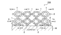
一方、図2で示す遮熱膜10Aは、粒子径も同程度で同素材のセラミックスからなる中空粒子1,…が金属相2と点接合して2層構造をなす遮熱膜である。
On the other hand, the
図1で示す遮熱膜10と比較して2層構造であることから、金属相2による点接合箇所の一部に不具合が生じた場合でも遮熱膜10Aとしての断熱性能を担保できるというメリットを有している。なお、本発明者等によれば、3層以上の遮熱膜を形成したとしてもその断熱性能が大きく向上しないことも特定されており、このことと材料コストや遮熱膜の形成効率等を総合勘案すれば、遮熱膜10,10Aのように1層構造もしくは2層構造の遮熱膜が好ましいと言える。
Since it has a two-layer structure as compared with the
一方、図3aで示す遮熱膜10Bは、粒径の異なる複数種類のセラミックス中空粒子1a,1b、1c、1d、1eを使用して形成された遮熱膜である。
On the other hand, the
また、図3bで示す遮熱膜10Cは、相対的に大径のセラミックス中空粒子1aからなる層を壁面Wに直接接合させ、この層の上に相対的に小径のセラミックス中空粒子1bからなる層を接合してなる2層構造の遮熱膜である。
Further, the
さらに、図3cで示す遮熱膜10Dは遮熱膜10Cと逆の構造であり、相対的に小径のセラミックス中空粒子1bからなる層を壁面Wに直接接合させ、この層の上に相対的に大径のセラミックス中空粒子1aからなる層を接合してなる2層構造の遮熱膜である。
Further, the
上記いずれの形態の遮熱膜であっても、その構造は網状構造を呈し、金属相2との点接合を介して強固かつ変形性能に富む態様で壁面Wと接合されている。
In any of the above forms of the heat shielding film, the structure has a network structure, and is bonded to the wall surface W through a point bonding with the
図4は、壁面の熱変形と、この熱変形に追随する遮熱膜の変形態様を説明した模式図である。 FIG. 4 is a schematic diagram for explaining the thermal deformation of the wall surface and the deformation mode of the thermal barrier film following the thermal deformation.
既述するように、遮熱膜10Aはセラミックス中空粒子1,…がそれぞれ金属相2と強固に点接合されて網状構造を呈していることから、金属母材の壁面Wが大きく熱膨張(X1方向)や熱収縮(X2方向)した場合であっても、界面の点接合をなす金属相2が変形し(Y1方向、Y2方向)、さらには、遮熱膜10Aを構成するセラミックス中空粒子1,1間の金属相2が同様に変形することで(Y1方向、Y2方向)、自身に亀裂等を生じさせることなく壁面Wの熱変形に追随することができる。
As described above, the
このことから、壁面Wの熱変形が激しい内燃機関の燃焼室においても、その壁面に形成された遮熱膜と壁面の間の界面剥離も生じ難くなり、高耐久な遮熱膜構造となる。 For this reason, even in the combustion chamber of an internal combustion engine in which the wall surface W is subjected to severe thermal deformation, interface peeling between the heat shield film formed on the wall surface and the wall surface hardly occurs, and a highly durable heat shield film structure is obtained.
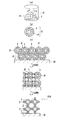
次に、図5を参照して本発明の遮熱膜の形成方法を概説する。図5は、図5a,b,cの順で遮熱膜の形成方法のフロー図となっている。なお、ここでは、金属粒としてAgナノ粒子を使用し、セラミックス中空粒子としてAl2O3とSiO2の複合材を使用する場合を取り上げる。 Next, the method for forming the heat shielding film of the present invention will be outlined with reference to FIG. FIG. 5 is a flowchart of a method for forming a thermal barrier film in the order of FIGS. 5a, 5b, and 5c. Here, the case where Ag nanoparticles are used as the metal particles and a composite material of Al 2 O 3 and SiO 2 is used as the ceramic hollow particles is taken up.
まず、図5aで示すように、容器K内にAl2O3とSiO2の複合材からなるセラミックス中空粒子1と、Agナノ粒子(平均粒径が300nm程度)、ガラスフリット、セルロース系樹脂、モノイソブチレート系溶剤からなるAgペーストPを投入し、十分に攪拌することにより、図5bで示すようにAl2O3とSiO2の複合材からなる中空粒子1の周りにAgペーストPが付着してなるスラリーSが生成される。
First, as shown in FIG. 5a, ceramic
なお、容器K内に投入されるAl2O3とSiO2の複合材からなるセラミックス中空粒子1の製作方法は次のとおりである。すなわち、不図示の回転チャンバー内に数十μm程度の平均粒径のポリマー粉体とサブミクロン以下のAl2O3粉体およびSiO2粉体を入れて回転チャンバーを高速回転させることにより、ポリマー粉体表面に可及的均一な厚みでAl2O3粉体やSiO2粉体がコーティングされた複合粒子を製造する。次いで、この複合粒子をたとえば1000℃以上で焼成して複合粒子を構成するポリマー粉体を熱分解(ガス化)することで、Al2O3とSiO2が結合してなる複合材からなる中空粒子を製造することができる。
Incidentally, a manufacturing method of the ceramic
生成されたスラリーSを図5cの上図のように壁面Wに塗工し、次いで、モノイソブチレート系溶剤の沸点である250℃程度以上の温度で加熱処理する。 The produced slurry S is applied to the wall surface W as shown in the upper diagram of FIG. 5c, and then heat-treated at a temperature of about 250 ° C. or higher, which is the boiling point of the monoisobutyrate solvent.
この加熱処理によって溶剤が揮発すると、図3cの中図で示すように中空粒子1の周囲でペーストPが凝縮する。
When the solvent is volatilized by this heat treatment, the paste P is condensed around the
さらに、Agナノ粒子の融点である500℃程度以上の温度で加熱処理することによって、溶剤の揮発が進展するとともに、中空粒子1,1間や中空粒子1と壁面W間では溶融したAgが毛細管現象によって縮みながら焼結していき、図3cの下図で示すように点接合をなす金属相2を形成して中空粒子1,1同士を接合し、かつ中空粒子1と壁面Wを接合する。
Further, by heat treatment at a temperature of about 500 ° C. or higher, which is the melting point of Ag nanoparticles, the volatilization of the solvent progresses, and molten Ag is formed between the
図6は、このような形成方法を経て形成された遮熱膜が内燃機関の燃焼室に臨む壁面に適用された実施例を示す縦断面図である。 FIG. 6 is a longitudinal sectional view showing an embodiment in which the heat shield film formed through such a forming method is applied to the wall surface facing the combustion chamber of the internal combustion engine.
図示する内燃機関Nは、ディーゼルエンジンをその対象としたものであり、その内部に冷却水ジャケットJが形成されたシリンダブロックSBと、シリンダブロックSB上に配設されたシリンダヘッドSHと、シリンダヘッドSH内に画成された吸気ポートKPおよび排気ポートHPとそれらが燃焼室NSに臨む開口に昇降自在に装着された吸気バルブKVおよび排気バルブHVと、シリンダブロックSBの下方開口から昇降自在に形成されたピストンPSから大略構成されている。なお、本発明の内燃機関がガソリンエンジンを対象としたものであってもよいことは勿論のことである。 The illustrated internal combustion engine N is intended for a diesel engine, a cylinder block SB having a cooling water jacket J formed therein, a cylinder head SH disposed on the cylinder block SB, and a cylinder head An intake port KP and an exhaust port HP defined in SH, an intake valve KV and an exhaust valve HV that are mounted so as to be able to be raised and lowered in an opening facing the combustion chamber NS, and a lower opening of the cylinder block SB are formed so as to be raised and lowered. The piston PS is generally constituted. Needless to say, the internal combustion engine of the present invention may be a gasoline engine.
この内燃機関Nを構成する各構成部材はともにアルミニウムもしくはその合金から形成されている。なお、構成部材がアルミニウムもしくはその合金以外の素材で形成され、かつ、構成部材の表面がアルミニウムもしくはその合金にてアルミ化されている形態であってもよい。 Each component constituting the internal combustion engine N is made of aluminum or an alloy thereof. The constituent member may be formed of a material other than aluminum or an alloy thereof, and the surface of the constituent member may be aluminized with aluminum or an alloy thereof.
また、内燃機関Nの各構成部材で画成された燃焼室NS内には、それらが燃焼室NSに臨む壁面(シリンダボア面SB’、シリンダヘッド底面SH’、ピストン頂面PS’、バルブ頂面KV’,HV’)において、所定の厚みを有した図2で示す遮熱膜10Aが形成されている。
Further, in the combustion chamber NS defined by each component of the internal combustion engine N, there are wall surfaces (cylinder bore surface SB ′, cylinder head bottom surface SH ′, piston top surface PS ′, valve top surface) facing the combustion chamber NS. KV ′, HV ′), the
内燃機関Nの燃焼室NSに臨む壁面に遮熱膜10Aが形成されていることから、この遮熱膜構造は高耐久で断熱性に優れており、さらには、燃焼室NS内のガス温度に遮熱膜10Aの温度が追随する、いわゆるスイング特性を有するものとなっている。
Since the
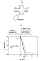
[冷却試験とその結果]
本発明者等は、冷却試験を実施して、本発明の遮熱膜が形成された内燃機関による燃費向上を確認する実験をおこなった。この冷却試験の概要は、図7aで示すように、片面のみに遮熱膜を施したテストピースTPを用い、背面(遮熱膜を施していない面)を750℃の高温噴射で加熱して(図中のHeat)テストピースTPの全体を250℃程度に安定させ、予め所定の流速で室温噴流を流しておいたノズルをリニアモーターでテストピースTPの正面(遮熱膜を施している面)に移動させて冷却を開始する(25℃の冷却エアー(図中のAir)を提供するものであり、この際に背面の高温噴射は継続する)。テストピースTPの遮熱膜表面の温度をその外部にある放射温度計で測定し、その冷却時の温度低下を測定して、図7bで示す冷却曲線を作成する。この冷却試験は燃焼室内壁の吸気行程を模擬した試験方法であり、加熱された遮熱膜表面の冷却速度を評価するものである。なお、低熱伝導率で低熱容量の遮熱膜の場合には急冷速度が速くなる傾向を示す。
[Cooling test and results]
The present inventors conducted a cooling test and conducted an experiment to confirm the improvement in fuel consumption by the internal combustion engine in which the thermal barrier film of the present invention was formed. As shown in FIG. 7a, the outline of this cooling test is as follows. A test piece TP having a thermal barrier film only on one surface is used, and the back surface (the surface without the thermal barrier film) is heated by high-temperature injection at 750 ° C. (Heat in the figure) The whole of the test piece TP is stabilized at about 250 ° C., and a nozzle that has flowed a room-temperature jet at a predetermined flow rate in advance is used as a front surface of the test piece TP with a linear motor. ) To start cooling (providing cooling air at 25 ° C. (Air in the figure), and high-temperature injection on the back surface continues at this time). The temperature of the surface of the heat shield film of the test piece TP is measured with a radiation thermometer located outside the test piece TP, and the temperature drop during cooling is measured to create a cooling curve shown in FIG. 7b. This cooling test is a test method that simulates the intake stroke of the combustion chamber wall, and evaluates the cooling rate of the surface of the heated thermal barrier film. In the case of a thermal barrier film having a low thermal conductivity and a low heat capacity, the rapid cooling rate tends to increase.
作成された冷却曲線から40℃低下するのに要する時間を読み取り、40℃降下時間として被膜の熱特性を評価する。本発明者等によれば、実験の際に、計測誤差として埋もれることなく燃費向上率を明確に証明でき、かつ、排気ガス温度の上昇によってNOX低減触媒の暖気時間を短縮し、NOX低減を実現できる値として燃費向上率5%を満たす260℃から220℃までの40℃降下時間として45msecが特定されており(500℃スイング特性)、この40℃降下時間が45msec以下となれば燃費向上率が5%以上となる。
The time required to decrease by 40 ° C. is read from the created cooling curve, and the thermal characteristics of the coating are evaluated as 40 ° C. drop time. According to the present inventors, during the experiment, it clearly demonstrated the fuel economy improvement ratio without being buried as a measurement error, and to shorten the warm-up time of the NO X reduction catalyst by increasing the exhaust gas temperature, NO X
本実験では、特許文献1,2で開示される従来構造の遮熱膜(比較例)と本発明の遮熱膜(実施例)を作製してそれぞれに冷却試験をおこない、それぞれの40℃降下時間を測定した。測定結果を図8に示している。
In this experiment, a heat shield film having a conventional structure disclosed in
同図より、比較例の40℃降下時間が50msecで燃費向上率が5%を達成できないのに対して、実施例は39msecと45msecを大きく下回っており、燃費向上率5%以上を達成できることが実証されている。 The figure shows that the fuel efficiency improvement rate cannot reach 5% when the 40 ° C drop time is 50 msec in the comparative example, whereas the embodiment is far below 39 msec and 45 msec, and the fuel efficiency improvement rate can be achieved at 5% or more. Proven.
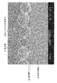
さらに、本発明者等は壁面上において、Al2O3とSiO2が結合してなる複合材からなる中空粒子が、銀ナノ粒子が溶解され、焼結されてできた金属相で点接合されてなる遮熱膜のSEM画像を撮像し、その全体写真図に加えて、金属組成像を確認した。図9は、壁面に形成された遮熱膜のSEM写真図であり、図10aは図9のSEM写真図におけるAg組成像を示す写真図であり、図10bはAl組成像を示す写真図であり、図10cはSi組成像を示す写真図である。 Furthermore, the inventors of the present invention have point-bonded hollow particles made of a composite material in which Al 2 O 3 and SiO 2 are bonded on the wall surface with a metal phase in which silver nanoparticles are dissolved and sintered. An SEM image of the thermal barrier film was taken, and in addition to the entire photograph, a metal composition image was confirmed. FIG. 9 is a SEM photograph of the thermal barrier film formed on the wall, FIG. 10a is a photograph showing an Ag composition image in the SEM photograph of FIG. 9, and FIG. 10b is a photograph showing an Al composition image. FIG. 10c is a photograph showing the Si composition image.
各図より、セラミックス中空粒子が金属相と点接合することで相互に接合されて層状に遮熱膜が形成されていること、遮熱膜を形成するセラミックス中空粒子と壁面もそれぞれが金属相と点接合することで相互に接合されていることが確認できる。 From each figure, the ceramic hollow particles are bonded to each other by the point-bonding with the metal phase to form a heat shield film in layers, and the ceramic hollow particles and the wall surface forming the heat shield film are also each a metal phase. It can be confirmed that they are joined together by spot joining.
以上、本発明の実施の形態を図面を用いて詳述してきたが、具体的な構成はこの実施形態に限定されるものではなく、本発明の要旨を逸脱しない範囲における設計変更等があっても、それらは本発明に含まれるものである。 The embodiment of the present invention has been described in detail with reference to the drawings. However, the specific configuration is not limited to this embodiment, and there are design changes and the like without departing from the gist of the present invention. They are also included in the present invention.
1,1a,1b,1c,1d,1e…セラミックス中空粒子、2…金属相、10,10A,10B,10C,10D…遮熱膜、W…壁面、P…ペースト、S…スラリー 1, 1a, 1b, 1c, 1d, 1e ... Ceramic hollow particles, 2 ... Metal phase, 10, 10A, 10B, 10C, 10D ... Thermal barrier film, W ... Wall surface, P ... Paste, S ... Slurry
Claims (10)
複数のセラミックス中空粒子が金属相と点接合することで相互に接合されて前記遮熱膜を形成しており、
前記遮熱膜を形成するセラミックス中空粒子と前記壁面もそれぞれが金属相と点接合することで相互に接合されている遮熱膜。 A thermal barrier film formed on the wall surface of the metal base material,
A plurality of ceramic hollow particles are bonded to each other by spot bonding with the metal phase to form the thermal barrier film,
The thermal barrier film in which the ceramic hollow particles forming the thermal barrier film and the wall surface are also bonded to each other by spot bonding with the metal phase.
金属母材の壁面に前記スラリーを塗布し、少なくとも溶剤の沸点以上の温度で加熱して前記溶剤を揮発させ、さらに少なくとも金属粒の溶融温度以上の温度で加熱することで金属粒を溶融させて複数のセラミックス中空粒子間で溶融金属が焼結してなる金属相を形成し、複数のセラミックス中空粒子が金属相と点接合することで相互に接合されて遮熱膜を形成し、かつ、遮熱膜を形成するセラミックス中空粒子と前記壁面も金属相を介して相互に点接合される遮熱膜の形成方法。 At least a metal particle paste composed of metal particles and a solvent and ceramic hollow particles are mixed to produce a slurry,
The slurry is applied to the wall surface of the metal base material, heated at a temperature equal to or higher than the boiling point of the solvent to volatilize the solvent, and further heated at a temperature equal to or higher than the melting temperature of the metal particles to melt the metal particles. A metal phase formed by sintering molten metal between a plurality of ceramic hollow particles is formed, and a plurality of ceramic hollow particles are bonded to each other by spot bonding with the metal phase to form a heat shielding film. A method for forming a thermal barrier film in which ceramic hollow particles forming a thermal film and the wall surface are also spot-bonded to each other through a metal phase.
Priority Applications (4)
| Application Number | Priority Date | Filing Date | Title |
|---|---|---|---|
| JP2010269567A JP5136629B2 (en) | 2010-12-02 | 2010-12-02 | Thermal barrier film and method for forming the same |
| PCT/IB2011/002890 WO2012073101A2 (en) | 2010-12-02 | 2011-12-01 | Heat-shielding film and method of forming the same |
| DE112011104022T DE112011104022T8 (en) | 2010-12-02 | 2011-12-01 | Heat-shielding layer and method for its formation |
| US13/988,634 US9051876B2 (en) | 2010-12-02 | 2011-12-01 | Heat-shielding film and method of forming the same |
Applications Claiming Priority (1)
| Application Number | Priority Date | Filing Date | Title |
|---|---|---|---|
| JP2010269567A JP5136629B2 (en) | 2010-12-02 | 2010-12-02 | Thermal barrier film and method for forming the same |
Publications (2)
| Publication Number | Publication Date |
|---|---|
| JP2012117482A true JP2012117482A (en) | 2012-06-21 |
| JP5136629B2 JP5136629B2 (en) | 2013-02-06 |
Family
ID=45491630
Family Applications (1)
| Application Number | Title | Priority Date | Filing Date |
|---|---|---|---|
| JP2010269567A Expired - Fee Related JP5136629B2 (en) | 2010-12-02 | 2010-12-02 | Thermal barrier film and method for forming the same |
Country Status (4)
| Country | Link |
|---|---|
| US (1) | US9051876B2 (en) |
| JP (1) | JP5136629B2 (en) |
| DE (1) | DE112011104022T8 (en) |
| WO (1) | WO2012073101A2 (en) |
Cited By (6)
| Publication number | Priority date | Publication date | Assignee | Title |
|---|---|---|---|---|
| JP2013204443A (en) * | 2012-03-27 | 2013-10-07 | Toyota Motor Corp | Internal combustion engine and method of manufacturing the same |
| JP2014088863A (en) * | 2012-10-31 | 2014-05-15 | Isuzu Motors Ltd | Internal combustion engine |
| JP2015117583A (en) * | 2013-12-16 | 2015-06-25 | マツダ株式会社 | Method of forming heat insulation layer |
| JP2018053879A (en) * | 2016-09-30 | 2018-04-05 | 日立オートモティブシステムズ株式会社 | Piston for internal combustion engine and method for manufacturing the same |
| JP2020012413A (en) * | 2018-07-18 | 2020-01-23 | 日立オートモティブシステムズ株式会社 | Manufacturing method of piston for internal combustion engine |
| JP2020076321A (en) * | 2018-11-05 | 2020-05-21 | トヨタ自動車株式会社 | Heat shielding coating of internal combustion engine and method for forming heat shielding coating |
Families Citing this family (6)
| Publication number | Priority date | Publication date | Assignee | Title |
|---|---|---|---|---|
| EP3219827A4 (en) | 2014-11-14 | 2018-04-11 | Hitachi, Ltd. | Heat-resistant member provided with heat-shielding coating, and method for manufacturing same |
| US10302013B2 (en) * | 2015-09-30 | 2019-05-28 | Corning Incorporated | Composite thermal barrier for combustion chamber surfaces |
| JP6638618B2 (en) * | 2016-10-19 | 2020-01-29 | トヨタ自動車株式会社 | Engine manufacturing method |
| JP6927057B2 (en) * | 2018-01-18 | 2021-08-25 | トヨタ自動車株式会社 | Compression self-ignition internal combustion engine |
| JP2021173213A (en) * | 2020-04-24 | 2021-11-01 | マツダ株式会社 | Combustion chamber structure of engine |
| EP4264033A1 (en) * | 2020-12-17 | 2023-10-25 | Cummins Inc. | Combustion cylinder end face components including thermal barrier coatings |
Citations (4)
| Publication number | Priority date | Publication date | Assignee | Title |
|---|---|---|---|---|
| JPS54141209U (en) * | 1978-03-27 | 1979-10-01 | ||
| JPS60184950A (en) * | 1984-03-02 | 1985-09-20 | Isuzu Motors Ltd | Internal-combustion engine having wall face of combustion chamber applied with heat insulating material |
| WO2009020206A1 (en) * | 2007-08-09 | 2009-02-12 | Kabushiki Kaisha Toyota Chuo Kenkyusho | Internal combustion engine |
| JP2010185291A (en) * | 2009-02-10 | 2010-08-26 | Toyota Central R&D Labs Inc | Heat insulating film and method of forming the same |
Family Cites Families (7)
| Publication number | Priority date | Publication date | Assignee | Title |
|---|---|---|---|---|
| US3888606A (en) * | 1973-12-26 | 1975-06-10 | Ford Motor Co | Rotary internal combustion engine |
| JPH07103816B2 (en) * | 1984-02-29 | 1995-11-08 | いすゞ自動車株式会社 | Internal combustion engine in which the wall of the combustion chamber is covered with a porous heat insulating material |
| US5477820A (en) * | 1994-09-29 | 1995-12-26 | Ford Motor Company | Thermal management system for heat engine components |
| US6916529B2 (en) * | 2003-01-09 | 2005-07-12 | General Electric Company | High temperature, oxidation-resistant abradable coatings containing microballoons and method for applying same |
| JP5082987B2 (en) | 2008-03-31 | 2012-11-28 | 株式会社豊田中央研究所 | Internal combustion engine |
| JP5457640B2 (en) | 2008-03-31 | 2014-04-02 | 株式会社豊田中央研究所 | Internal combustion engine |
| JP5315308B2 (en) | 2010-08-25 | 2013-10-16 | トヨタ自動車株式会社 | Internal combustion engine and manufacturing method thereof |
-
2010
- 2010-12-02 JP JP2010269567A patent/JP5136629B2/en not_active Expired - Fee Related
-
2011
- 2011-12-01 US US13/988,634 patent/US9051876B2/en not_active Expired - Fee Related
- 2011-12-01 DE DE112011104022T patent/DE112011104022T8/en not_active Ceased
- 2011-12-01 WO PCT/IB2011/002890 patent/WO2012073101A2/en active Application Filing
Patent Citations (4)
| Publication number | Priority date | Publication date | Assignee | Title |
|---|---|---|---|---|
| JPS54141209U (en) * | 1978-03-27 | 1979-10-01 | ||
| JPS60184950A (en) * | 1984-03-02 | 1985-09-20 | Isuzu Motors Ltd | Internal-combustion engine having wall face of combustion chamber applied with heat insulating material |
| WO2009020206A1 (en) * | 2007-08-09 | 2009-02-12 | Kabushiki Kaisha Toyota Chuo Kenkyusho | Internal combustion engine |
| JP2010185291A (en) * | 2009-02-10 | 2010-08-26 | Toyota Central R&D Labs Inc | Heat insulating film and method of forming the same |
Cited By (9)
| Publication number | Priority date | Publication date | Assignee | Title |
|---|---|---|---|---|
| JP2013204443A (en) * | 2012-03-27 | 2013-10-07 | Toyota Motor Corp | Internal combustion engine and method of manufacturing the same |
| JP2014088863A (en) * | 2012-10-31 | 2014-05-15 | Isuzu Motors Ltd | Internal combustion engine |
| JP2015117583A (en) * | 2013-12-16 | 2015-06-25 | マツダ株式会社 | Method of forming heat insulation layer |
| JP2018053879A (en) * | 2016-09-30 | 2018-04-05 | 日立オートモティブシステムズ株式会社 | Piston for internal combustion engine and method for manufacturing the same |
| WO2018061591A1 (en) * | 2016-09-30 | 2018-04-05 | 日立オートモティブシステムズ株式会社 | Piston for internal combustion engine and method for manufacturing piston for internal combustion engine |
| JP2020012413A (en) * | 2018-07-18 | 2020-01-23 | 日立オートモティブシステムズ株式会社 | Manufacturing method of piston for internal combustion engine |
| WO2020017192A1 (en) * | 2018-07-18 | 2020-01-23 | 日立オートモティブシステムズ株式会社 | Method for manufacturing internal-combustion engine piston |
| JP2020076321A (en) * | 2018-11-05 | 2020-05-21 | トヨタ自動車株式会社 | Heat shielding coating of internal combustion engine and method for forming heat shielding coating |
| JP7119916B2 (en) | 2018-11-05 | 2022-08-17 | トヨタ自動車株式会社 | Thermal barrier coating for internal combustion engine and method for forming thermal barrier coating |
Also Published As
| Publication number | Publication date |
|---|---|
| WO2012073101A2 (en) | 2012-06-07 |
| JP5136629B2 (en) | 2013-02-06 |
| DE112011104022T8 (en) | 2013-11-07 |
| DE112011104022T5 (en) | 2013-09-05 |
| US20130239924A1 (en) | 2013-09-19 |
| US9051876B2 (en) | 2015-06-09 |
| WO2012073101A3 (en) | 2012-07-26 |
Similar Documents
| Publication | Publication Date | Title |
|---|---|---|
| JP5136629B2 (en) | Thermal barrier film and method for forming the same | |
| CN107225241B (en) | Method of fabricating thermally insulating three-dimensional (3D) structures using 3D printing | |
| CN103415365B (en) | Process for local repair of a damaged thermomechanical part and part thus produced, in particular a turbine part | |
| EP2193217B1 (en) | Imparting functional characteristics to engine portions | |
| US20120272653A1 (en) | Internal combustion engine hot gas path component with powder metallurgy structure | |
| CN108495946A (en) | Heat-insulated engine components and the manufacturing method using ceramic coating | |
| JP5928419B2 (en) | Thermal barrier film and method for forming the same | |
| JP5784913B2 (en) | Tube body and exhaust gas system | |
| US10267260B2 (en) | Heat-resistant member provided with heat-shielding coating, and method for manufacturing same | |
| CN109706418A (en) | A kind of double ceramic layer structure 8YSZ thermal barrier coatings and preparation method | |
| CN108251832B (en) | Method of depositing one or more layers of microspheres to form a thermal barrier coating | |
| US11466370B2 (en) | Turbine engine part coated in a thermal barrier, and a method of obtaining it | |
| JP2006193828A (en) | Heat-shielding coating material, heat-shielding member, heat-shielding coating member, and method for production of the heat-shielding coating member | |
| JP6109101B2 (en) | Method of manufacturing a metal-ceramic composite structure and metal-ceramic composite structure | |
| CN106232855A (en) | There is controlled defect structure thermal barrier coating | |
| US20190194812A1 (en) | Gap-filling sealing layer of thermal barrier coating | |
| US20190366441A1 (en) | Composite material for turbo machine applications and corresponding method | |
| JP2002517608A (en) | Method for producing adhesive layer for heat insulation layer | |
| JPS6055699B2 (en) | Engine parts with contact surfaces | |
| CN108220865A (en) | The thermal spray deposition of hollow microsphere | |
| KR102463179B1 (en) | Aluminum foam core piston with coaxial laser bonded aerogel/ceramic head | |
| US20190107045A1 (en) | Multi-layer thermal barrier | |
| US20150083787A1 (en) | Method for fixing heat resistant component on a surface of a heat exposed component | |
| JPS61169241A (en) | Heat-insulating member | |
| JPS63161150A (en) | Formation of heat insulating thermally sprayed layer |
Legal Events
| Date | Code | Title | Description |
|---|---|---|---|
| A977 | Report on retrieval |
Free format text: JAPANESE INTERMEDIATE CODE: A971007 Effective date: 20121009 |
|
| TRDD | Decision of grant or rejection written | ||
| A01 | Written decision to grant a patent or to grant a registration (utility model) |
Free format text: JAPANESE INTERMEDIATE CODE: A01 Effective date: 20121016 |
|
| A01 | Written decision to grant a patent or to grant a registration (utility model) |
Free format text: JAPANESE INTERMEDIATE CODE: A01 |
|
| A61 | First payment of annual fees (during grant procedure) |
Free format text: JAPANESE INTERMEDIATE CODE: A61 Effective date: 20121029 |
|
| FPAY | Renewal fee payment (event date is renewal date of database) |
Free format text: PAYMENT UNTIL: 20151122 Year of fee payment: 3 |
|
| LAPS | Cancellation because of no payment of annual fees |