JP2012116501A - Nozzle head - Google Patents
Nozzle head Download PDFInfo
- Publication number
- JP2012116501A JP2012116501A JP2010266449A JP2010266449A JP2012116501A JP 2012116501 A JP2012116501 A JP 2012116501A JP 2010266449 A JP2010266449 A JP 2010266449A JP 2010266449 A JP2010266449 A JP 2010266449A JP 2012116501 A JP2012116501 A JP 2012116501A
- Authority
- JP
- Japan
- Prior art keywords
- tip
- nozzle
- locking
- discharge
- discharge cover
- Prior art date
- Legal status (The legal status is an assumption and is not a legal conclusion. Google has not performed a legal analysis and makes no representation as to the accuracy of the status listed.)
- Pending
Links
Images


Landscapes
- Closures For Containers (AREA)
Abstract
Description
本発明は、容器内に充填された口内洗浄剤や消毒用アルコールなど粘性が低く固化しにくい内容液を注出するための手動押下げ注出ポンプ用のノズルヘッドに関する。 The present invention relates to a nozzle head for a manual push-out dispensing pump for dispensing a liquid having a low viscosity and difficult to solidify, such as a mouth rinse or a disinfecting alcohol filled in a container.
化粧料や整髪料、シャンプーあるいはリンス等を入れる容器としては、ハンディータイプや据え置きタイプに関わらずポンプを装着したものが多数市販されており、容器の外に設けられたノズルヘッドを押し下げることにより、ノズルの先端から容器内の内容液を衛生的、かつ効率的に注出することができるようになっている。このようなノズルヘッドに関する先行技術としては、例えば以下の特許文献1などが存在している。
As containers for cosmetics, hair styling, shampoos, rinses, etc., many are equipped with pumps regardless of handy type or stationary type, and by depressing the nozzle head provided outside the container, The content liquid in the container can be poured out hygienically and efficiently from the tip of the nozzle. As prior art relating to such a nozzle head, for example, the following
特許文献1に記載のノズルヘッドは、下方に開口する吐出口部とノズル基体とからなる吐出ノズルと、押圧ヘッド部とを具備し、吐出口部は、ノズル基体の先端面上端にヒンジを介して連設されており、ヒンジに近接して吐出口部の上面とノズル基体の上面に相互に係合し合う係止部を設け、吐出口部を、ヒンジを中心に回動させ、それぞれの係止部を係合させることによって、容器内の内溶液をノズル基体先端の流出口から吐出するようにしたものである。
The nozzle head described in
特許文献1に記載されたノズルヘッドでは、吐出口部が回動自在に装着されると共に、吐出口部の上面とノズル基体の上面に相互に係合し合う係止部が係止解除可能に構成されている。そして、吐出口部を回動させて係合部を係止状態に設定することにより、吐出口部の吐出方向を下向きに設定することができ、吐出終了後に、係止部の係止状態を解除し吐出口部を逆方向に回動させて流出口を露出させることにより、吐出口部及びノズル基体の流路内に残って付着している内容液を取り除いて、吐出ノズルの掃除をすることができるようになっている。このため、例えばボディソープ、ハンドソープなど固化しやすい内容液でも、このノズルヘッドを利用して吐出させることができるという優れた効果を有する。
In the nozzle head described in
しかしながら、例えば内溶液の対象が口内洗浄剤や消毒用のアルコールなど固化しにくい液体である場合に、係止部が係止状態に設定されていない状態でノズルヘッドが押し下げられると、内溶液が露出した流出口から周囲に飛散することがあり、飛散した内溶液が操作者の目などに入って不測の事故を引き起こす虞れがあるという問題があった。 However, for example, when the target of the inner solution is a liquid that is difficult to solidify, such as a mouthwash or alcohol for disinfection, if the nozzle head is pushed down without the locking portion being set to the locked state, the inner solution There is a problem that the exposed outlet may scatter to the surroundings, and the scattered internal solution may enter the eyes of the operator and cause an unexpected accident.
本発明は、上記した従来技術における問題点を解消すべく、ノズルヘッドの先端の流出口の近傍に吐出口部(以下の説明では「吐出カバー部」)を抜脱不能に取り付けることにより、ノズルヘッドを押し下げたときに粘性の低い内溶液の飛散を防止して安全性に優れた手動押下げ注出ポンプ用のノズルヘッドを創出することを課題とする。 In order to solve the above-described problems in the prior art, the present invention provides a nozzle by attaching a discharge port portion (hereinafter referred to as “discharge cover portion”) in the vicinity of the outlet at the tip of the nozzle head in a non-removable manner. It is an object of the present invention to create a nozzle head for a manual push-down dispensing pump that is excellent in safety by preventing scattering of an internal solution having a low viscosity when the head is pushed down.
上記課題を解決するための手段のうち、本発明の主たる構成は、ポンプに連結されたステムの先端に取り付けられる押圧ヘッド部と、押圧ヘッド部に形成され且つポンプが吸い上げた内容液を案内する吐出路を備えたノズル筒と、ノズル筒の先端に装着されて内溶液の吐出方向を設定する吐出カバー部と、を有するノズルヘッドにおいて、
ノズル筒の先端と吐出カバー部との一方に係止凹部が設けられ、他方に係止凸部が設けられており、係止凹部と係止凸部とが互いに分離不能にアンダーカット結合することにより、吐出カバー部に形成された吐出口の吐出方向が下向きに設定されていることを特徴とする、と云うものである。
Among the means for solving the above-mentioned problems, the main configuration of the present invention is to guide the contents of the pressure head part attached to the tip of the stem connected to the pump and the liquid formed on the pressure head part and sucked up by the pump. In a nozzle head having a nozzle cylinder provided with a discharge path, and a discharge cover part that is attached to the tip of the nozzle cylinder and sets the discharge direction of the internal solution,
A locking recess is provided on one of the tip of the nozzle cylinder and the discharge cover portion, and a locking projection is provided on the other, and the locking recess and the locking projection are undercut coupled so that they cannot be separated from each other. Thus, the discharge direction of the discharge port formed in the discharge cover portion is set downward.
上記構成のノズルヘッドでは、係止凸部と係止凹部とがアンダーカット結合する構成とすることにより、係止状態に容易に至らしめ、係止後は係止凸部と係止凹部の分離を不可能として非係止状態に至ることを確実に防止する。 In the nozzle head having the above-described configuration, the locking projection and the locking recess are undercut coupled so that the locking state is easily achieved. After locking, the locking projection and the locking recess are separated. It is possible to reliably prevent the non-locking state from being made impossible.
本発明の具体的な構成は、係止凸部がノズル筒の先端に設けられた先筒部の両側面に突出形成された係止突片であり、係止凹部が吐出カバー部の両側部に形成された貫通孔である、と云うものである。 A specific configuration of the present invention is a locking protrusion that is formed on both side surfaces of a tip tube portion provided at the tip of the nozzle tube, and the locking recess is on both sides of the discharge cover portion. It is said that it is the through-hole formed in this.
上記構成では、吐出カバー部をノズル筒の先端に装着するだけで、係止凸部を構成する係止突片が係止凹部を構成する貫通孔にアンダーカット結合する係止状態に容易に至らしめると共に、係止後は係止突片と貫通孔との分離が不可能となって非係止状態に至ることを防止する。 In the above configuration, simply by attaching the discharge cover portion to the tip of the nozzle cylinder, the locking protrusions constituting the locking projections can be easily brought into a locked state where they are undercut coupled to the through holes forming the locking recesses. At the same time, after the locking, it is impossible to separate the locking projection piece and the through hole, thereby preventing the locked state.
また本発明の他の構成は、請求項2に記載の構成において、貫通孔から突出した係止突片の先端が、貫通孔の縁部に拡開状に変形されている、と云うものである。
According to another configuration of the present invention, in the configuration according to
上記構成では、拡開した係止突片の先端が貫通孔に強固に係止されるため、係止凸部と係止凹部との分離をさらに困難とする。 In the above configuration, since the distal end of the expanded locking projection piece is firmly locked in the through hole, it is further difficult to separate the locking projection from the locking recess.
さらなる本発明の他の構成は、請求項2に記載の構成において、貫通孔の内部から表面にかけて徐々に拡開するテーパー部が形成されており、係止突片の先端がテーパー部内において拡開状に変形されている、と云うものである。
According to still another configuration of the present invention, in the configuration according to
上記構成では、係止凸部と係止凹部との分離をさらに困難にすると共に、係止凸部の先端が貫通孔の外部に突出することが防止される。 In the above configuration, it is further difficult to separate the locking projection from the locking recess, and the tip of the locking projection is prevented from protruding outside the through hole.
また具体的な本発明の他の構成は、係止凹部がノズル筒の先端に突出形成された先筒部とノズル筒の先端との間の前段差部に形成された貫通孔であり、係止凸部が係止状態において前段差部と面対向する吐出カバー部の端面に突出形成された弾性腕に設けられた係止突片である、と云うものである。 In addition, another specific configuration of the present invention is a through hole formed in a front step portion between a tip tube portion in which a locking recess projects from the tip of the nozzle tube and a tip of the nozzle tube. It is said that the locking projection is a locking projection provided on an elastic arm protruding from the end face of the discharge cover portion facing the front step portion in the locked state.
上記構成においても、吐出カバー部をノズル筒の先端に装着するだけで、係止凸部と係止凹部とをアンダーカット結合する係止状態に設定すると共に、係止後は係止凸部とが係止凹部とが分離して非係止状態に至ることを不可能とする。 Even in the above-described configuration, the locking projection and the locking recess are set to the locked state in which the undercut coupling is performed by simply attaching the discharge cover portion to the tip of the nozzle cylinder, and after locking, the locking projection and However, it is impossible to separate the locking recess and reach the non-locking state.
また本発明のさらなる構成は、上記いずれかの請求項において、吐出カバー部が、ノズル筒の先端にヒンジを介して回動自在に連設されている、と云うものである。 According to a further configuration of the present invention, in any one of the above claims, the discharge cover portion is rotatably connected to the tip of the nozzle cylinder via a hinge.
上記構成では、吐出カバー部を一方向に回動させると、係止凹部と係止凸部とがアンダーカット結合し、吐出カバー部がノズル筒の先端に抜脱不能に装着される。 In the above configuration, when the discharge cover portion is rotated in one direction, the locking concave portion and the locking convex portion are undercut coupled, and the discharge cover portion is attached to the tip of the nozzle cylinder so as not to be removable.
本発明は、上記した構成となっているので、以下に示す効果を奏する。
本発明の主たる構成においては、吐出カバー部がノズル筒体の先端に装着されて流出口を覆う係止状態に至った後は、非係止状態に至ることがなくなる。これにより、吐出カバー部が抜脱不能に装着され、内溶液はノズル筒先端に形成された流出口を介して吐出されることがなくなり、必ず吐出カバー部に設けられ且つ常に吐出方向が下向きに設定された吐出口を介して吐出されるようになるため、吐出時に粘性の低い内溶液が周囲に飛散することを確実に防止することが可能となり、安全性に優れたノズルヘッドとすることができる。
Since the present invention has the above-described configuration, the following effects can be obtained.
In the main configuration of the present invention, after the discharge cover portion is attached to the tip of the nozzle cylinder and reaches the locked state covering the outlet, the non-locked state is not reached. As a result, the discharge cover portion is mounted in a non-removable manner, and the internal solution is not discharged through the outlet formed at the tip of the nozzle cylinder, and is always provided in the discharge cover portion and the discharge direction is always downward. Since the liquid is discharged through the set discharge port, it is possible to reliably prevent the inner solution having low viscosity from being scattered to the surroundings at the time of discharge, and to make the nozzle head excellent in safety. it can.
また係止凸部がノズル筒の先端に設けられた先筒部の両側面に突出形成された係止突片であり、係止凹部が吐出カバー部の両側部に形成された貫通孔である構成としたものでは、吐出カバー部をノズル筒の先端に装着するだけで、容易にアンダーカット結合による係止状態に設定することができると共に、非係止状態に至ることを不可能とし、吐出カバー部がノズル筒先端から抜脱することを防止することができる。 Also, the locking projection is a locking protrusion formed on both side surfaces of the tip tube portion provided at the tip of the nozzle tube, and the locking recess is a through-hole formed on both sides of the discharge cover portion. With the configuration, simply attaching the discharge cover to the tip of the nozzle cylinder makes it possible to easily set the locked state by the undercut coupling and make it impossible to reach the non-locked state. It is possible to prevent the cover portion from being pulled out from the tip of the nozzle cylinder.
また貫通孔から突出した係止突片の先端を、貫通孔の縁部に拡開状に変形される構成としたものでは、より確実に係止凸部と係止凹部の係止状態からの分離を不可能とし、吐出カバー部がノズル筒先端から抜脱することを防止することができる。 In addition, in the configuration in which the tip of the locking protrusion protruding from the through hole is deformed to be widened at the edge of the through hole, the locking protrusion and the locking recess are more reliably released from the locked state. Separation is impossible, and the discharge cover portion can be prevented from being pulled out from the tip of the nozzle cylinder.
また貫通孔の内部から表面にかけて徐々に拡開するテーパー部を形成し、係止突片の先端がテーパー部内において拡開状に変形させる構成としたものでは、係止後における係止凸部と係止凹部との分離をより確実に防止できると共に、係止凸部の先端が貫通孔の内部に納まって貫通孔の外部に突出することがなくなるため、例えば係止凸部の先端に引っ掛かって手などが傷つくようなことがなくなり、この点で安全性に優れたノズルヘッドとすることができる。 In addition, a taper portion that gradually expands from the inside to the surface of the through hole is formed, and the tip of the locking protrusion is configured to be expanded in the taper portion. Separation from the locking recess can be prevented more reliably, and the tip of the locking projection is housed inside the through hole and does not protrude outside the through hole. Hands and the like are not damaged, and in this respect, the nozzle head can be made excellent in safety.
また係止凹部がノズル筒の先端に突出形成された先筒部とノズル筒の先端との間の前段差部に形成された貫通孔であり、係止凸部が係止状態において前段差部と面対向する吐出カバー部の端面に突出形成された弾性腕に設けられた係止突片であるという構成のものでも、吐出カバー部をノズル筒の先端に装着するだけで、簡単にアンダーカット結合による係止状態に設定することができると共に、非係止状態に至ることを不可能とし、吐出カバー部がノズル筒先端から抜脱することを防止することができる。 The locking recess is a through hole formed in the front step portion between the tip tube portion formed at the tip of the nozzle tube and the tip of the nozzle tube, and the locking protrusion is the front step portion in the locked state. Even with a structure that is a locking protrusion provided on the elastic arm that protrudes from the end face of the discharge cover that faces the surface, simply by attaching the discharge cover to the tip of the nozzle cylinder, you can easily undercut While being able to set to the locked state by coupling, it is impossible to reach the unlocked state, and it is possible to prevent the discharge cover portion from being detached from the tip of the nozzle cylinder.
さらに吐出カバー部が、ノズル筒の先端にヒンジを介して回動自在に連設される構成としたものでは、吐出カバー部を一方向に回動させるだけで、簡単且つ迅速に吐出カバー部をノズル筒の先端に抜脱不能に装着することが可能となる。また吐出カバー部を押圧ヘッド部、ノズル部及び連結部などと一体成形することができるため、部品点数を削減することが可能となる。 Further, in the case where the discharge cover portion is configured to be connected to the tip of the nozzle cylinder so as to be rotatable via a hinge, the discharge cover portion can be easily and quickly moved by simply rotating the discharge cover portion in one direction. It becomes possible to attach the tip of the nozzle cylinder so as not to be removable. In addition, since the discharge cover portion can be integrally formed with the pressing head portion, the nozzle portion, the connecting portion, and the like, the number of parts can be reduced.
以下、本発明の実施の形態について図面を参照しつつ説明する。
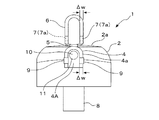
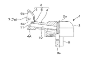
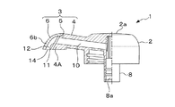
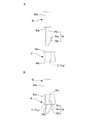
図1乃至図6は本発明の第1実施例としてのノズルヘッドを示している。図1はノズルヘッドの係止状態を示し、Aは側面図、Bは平面図、Cは底面図、図2はノズルヘッドの非係止状態を示し、Aは側面図、Bは平面図、Cは底面図、図3はノズルヘッドの非係止状態を示す正面図、図4はノズルヘッドの非係止状態における半断面図、図5はノズルヘッドの係止状態における半断面図、図6は係止部の構成例を示す図1のVI−VIに相当する断面図であり、Aは第1構成例、Bは第2構成例、Cは第3構成例をそれぞれ示している。
Embodiments of the present invention will be described below with reference to the drawings.
1 to 6 show a nozzle head as a first embodiment of the present invention. 1 shows a locked state of the nozzle head, A is a side view, B is a plan view, C is a bottom view, FIG. 2 shows a non-locked state of the nozzle head, A is a side view, B is a plan view, C is a bottom view, FIG. 3 is a front view showing a non-locked state of the nozzle head, FIG. 4 is a half cross-sectional view of the nozzle head in a non-locked state, and FIG. 6 is a cross-sectional view corresponding to VI-VI in FIG. 1 showing a configuration example of the locking portion, A is a first configuration example, B is a second configuration example, and C is a third configuration example.
本発明のノズルヘッド1は射出成形法により一体成形された合成樹脂製であり、図示しない容器内のポンプから容器の外部に延びたステムの先端に取り付けられて使用されるものである。
The
図1及び図2等に示すように、ノズルヘッド1は、押圧ヘッド部2、ノズル部3及び連結部8を有して形成されている。この実施例に示すノズル部3は、押圧ヘッド部2の側面から略水平方向に延びる円筒状のノズル筒4と、このノズル筒4の先端に形成された先筒部4Aと、ノズル筒4の先端に抜脱不能に装着されて先筒部4Aを覆う吐出カバー部6と、ノズル筒4の先端と吐出カバー部6との間に連設されて吐出カバー部6を回動自在に連結するヒンジ5とを有して構成されている。
As shown in FIGS. 1 and 2, the
押圧ヘッド部2の頂部2aの下面には,円筒状からなる連結部8が垂設されている。この連結部8の内部には流路8aが形成されている。連結部8が図示しない容器内に設けられたポンプから容器の外部に延びるステムの先端に連結されることにより、ノズルヘッド1が容器の口筒部の上部に取り付けられる。
A connecting
ノズル筒4の内部には内溶液が流れる吐出路10が形成されている。吐出路10の一端は先筒部4Aの端面に開口形成された流出口11に連結され、他端は押圧ヘッド部2の中心方向に延び、連結部8内の流路8aに連通されている。
A
図3に示すように、ノズル筒4の先端に形成された先筒部4Aは、ノズル筒4の先端部分よりもΔwだけ小さな寸法で形成され、ノズル筒4の先端と先筒部4Aの基部との間には逆U字形状からなる前段差部4aが形成されている。なお、前段差部4aの幅寸法がΔwに相当する。
As shown in FIG. 3, the
前段差部4aはノズル筒4先端の端面に相当しており、その逆側(押圧ヘッド部2側)でノズル筒4の外周面の下端部には略鰓(えら)状に張り出した後段差部4bが形成されている。
The
前段差部4aの近傍で且つ先筒部4Aの両側面には、外側方向に突出する係止突片9aからなる一対の係止凸部9,9がそれぞれ形成されており、これら係止凸部9には傾斜部9bが設けられている。
A pair of locking
吐出カバー部6はフード状に形成され、吐出カバー部6を形成するカバー壁6bの肉厚寸法は前段差部4aと同じΔwである(図3参照)。そして、吐出カバー部6の両側面には角状の貫通孔7aからなる係止凹部7,7が形成されている。なお、貫通孔7aからなる係止凹部7と係止突片9aからなる係止凸部9とが係止部を構成している。
The
吐出カバー部6は、ヒンジ5を介してノズル筒4の上端部に連設されており、射出成形直後の非係止状態では吐出カバー部6は回動可能な状態にある。
The
次に、ノズルヘッドの製造及び組立の方法について説明する。
ノズルヘッド1の射出成形では、吐出カバー部6がヒンジ5を介してノズル筒4の上方にほぼ90°回動させた非係止状態の姿勢(図2及び図4参照)における成形金型を形成し、流出口11側から吐出路10を形成する成形用ピンを備えるスライドコアを用いることにより一体に成形される。
Next, a method for manufacturing and assembling the nozzle head will be described.
In the injection molding of the
吐出カバー部6を90°回動させることなく、ノズル筒4先端に係止状態の姿勢で一体的に射出成形する方法では、成形用ピンの形状が略L字状となるため、成形用ピンの無理抜き可能な許容範囲を超えてしまって成形不可能となる。しかしながら、本発明のように吐出カバー部6をほぼ90°回動させた非係止状態の姿勢で成形することにより、成形用ピンの形状を略直線状とすることができ、成形用ピンを容易に引き抜くことで容易に成形することが可能となる。
In the method of injection molding integrally with the
成形後、図2に示す非係止状態から、吐出カバー部6の両側面の内側に、先筒部4Aの両側面を挿入させて先筒部4Aを覆うように吐出カバー部6を回動させ、吐出カバー部6の係止凹部7,7と先筒部4Aの係止凸部9,9とが係止し合う係止状態(図1A及び図5参照)に設定する。この際、係止凸部9,9の傾斜部9b,9bが吐出カバー部6の両側内面をそれぞれ摺動し、両側面の対向間隔を押し広げる。そして、係止突片9a,9aが係止凹部7,7を形成する貫通孔7a,7aに嵌まり込んでアンダーカット結合することにより、ノズルヘッド1の組み立てが完了する。
After molding, from the non-locking state shown in FIG. 2, the
この係止状態では、吐出カバー部6の端面6aが前段差部4aであるノズル筒4の端面に当接し、吐出カバー部6の両側面とノズル筒4の先端側の両側面とがほぼ同一平面に設定される。そして、図5に示すように、吐出カバー部6のカバー壁6bと先筒部4Aの先端の端面との間に流出口11から続く排出路12が形成され、この排出路12の末端に内溶液の吐出方向を下向きに設定する吐出口14が形成される。
In this locked state, the
本発明のノズルヘッド1では、一方の手で押圧ヘッド部2の頂部2aに押し当てノズルヘッド1を押し下げると、図示しない容器内のポンプが内溶液を汲み上げる。そして、汲み上げられた内溶液は、連結部8内の流路8a及びノズル筒4内の吐出路10を通って流出口11に案内され、さらに吐出カバー部6内の排出路12を通って吐出口14に至る。このとき、他方の手を吐出口14の下にあてがうことにより、内溶液が他方の手に吐出される。
In the
本発明では、係止凸部9が係止凹部7に嵌まり込んでアンダーカット結合して係止状態に至るため、吐出カバー部6をノズル筒4の先端に容易に装着することができる。また一度係止状態に至った後の係止部は、係止凹部7と係止凸部9との分離が不可能となって容易に非係止状態に至ることができなくなるため、吐出カバー部6が逆方向に回動することを規制してノズル筒4の先端から抜脱してしまうことを防止することができる。これにより、常に吐出カバー部6の吐出口14の向きが下向きとなる状態を維持することができ、吐出口14から吐出した内容液が周囲に飛散して目に入るという不測の事故の発生を確実に防止することが可能となる。すなわち、安全性に優れたノズルヘッド1とすることができる。
In the present invention, the locking
次に、係止部の構成例について説明する。
図6Aに示す係止部の第1構成例は、係止凸部9を構成する係止突片9aの板厚方向の高さ寸法を、係止凹部7を構成する貫通孔7aの深さ寸法よりも小さく設定している。これにより、例え係止凸部9が傾斜部9bを有しない構成であっても、係止凹部7と係止凸部9とのアンダーカット結合が容易に達成され、係止状態に確実に導くことができる。
Next, a configuration example of the locking portion will be described.
In the first configuration example of the locking portion shown in FIG. 6A, the height dimension of the locking
このように第1構成例では係止凹部7と係止凸部9とをアンダーカット結合させることができるが、より強固にアンダーカット結合させることが可能な構成例としては以下に示すような方法がある。
図6Bに示す係止部の第2構成例では、係止凸部9の板厚方向の寸法を係止凹部7の深さ寸法よりも大きくなるように設定してある。なお、説明の都合上、図6Bの左側に示す係止部と右側に示す係止部とでは、係止凸部9の先端の処理方法が異なっている。
As described above, in the first configuration example, the locking
In the second configuration example of the locking portion shown in FIG. 6B, the dimension in the plate thickness direction of the locking
図6Bの左側に示す係止部は、係止状態に至った後に係止凸部9を構成する係止突片9aの先端に熱を加えながらカシメ変形させることにより、係止突片9aの先端部を潰して貫通孔(7a)の縁部に拡開状に押し広げたものである。
The locking portion shown on the left side of FIG. 6B is deformed by caulking deformation while applying heat to the tip of the locking
また図6Bの右側に示す係止部は、係止突片9aの先端にクサビを打ち込んで係止突片9aを変形させた後、クサビを外して係止突片9aにスリット9dを形成することにより、貫通孔7aの外部に突出する係止突片9aの先端部を拡開状に押し広げたものである。
In addition, the locking portion shown on the right side of FIG. 6B forms a
図6A及び図6Bに示す構成例では、共に貫通孔7aの外部に拡開した係止突片9aの先端部分が貫通孔7aの上縁に強固に係止されるため、通常の使用状態における力を加えた程度では、係止突片9aが貫通孔7aから抜け出ることを防止し、係止状態から非係止状態に至ることを不可能とする。これにより、吐出カバー部6の逆方向への回動を規制してノズル筒4の先端から抜脱してしまうことを防止し、常に吐出カバー部6の吐出口14の向きが下向きとなる状態を維持することができる。
In the configuration example shown in FIGS. 6A and 6B, since the leading end portion of the locking
図6Cに示す係止部の第3構成例では、係止凹部7を形成する貫通孔7aの表面側に内部から外部方向に徐々に拡開するテーパー部7bを形成すると共に、係止突片9aの板厚方向の高さ寸法を貫通孔7aの深さ寸法よりも小さく設定している。なお、係止凸部9を形成する係止突片9aの先端部分の処理は、上述の図6Bの左側及び右側の場合とそれぞれ同様である。
In the third configuration example of the locking portion shown in FIG. 6C, a tapered
図6Cに示す係止部の第3構成例では、図6Aに示す第1構成例同様にアンダーカット結合による係止状態を設定し易くすることができると共に、図6Bに示す第2構成例同様に貫通孔7aと係止突片9aとによる係止部が係止状態から非係止状態に至ることを不可能とし、吐出カバー部6が逆方向に回動することを規制してノズル筒4の先端に装着した状態から外れてしまうことを防止し、常に吐出カバー部6の吐出口14の向きが下向きとなる状態を維持することが可能となる。
In the third configuration example of the locking portion shown in FIG. 6C, it is possible to easily set the locking state by the undercut coupling as in the first configuration example shown in FIG. 6A, and the same as the second configuration example shown in FIG. 6B. In this way, the locking portion formed by the through-
図7乃至図11は本発明の第2実施例としてのノズルヘッドを示し、図7はノズルヘッドの非係止状態を側面方向から見た半断面図、図8はノズルヘッドの非係止状態を示す正面図、図9は係止部を拡大して示す部分平面図であり、Aは非係止状態、Bは係止状態、図10及び図11はノズルヘッドを構成するノズル部を拡大して示すノズルヘッドの部分側面図であり、図10は非係止状態、図11は係止状態、をそれぞれ示している。 7 to 11 show a nozzle head as a second embodiment of the present invention, FIG. 7 is a half sectional view of the non-locking state of the nozzle head as viewed from the side, and FIG. 8 is the non-locking state of the nozzle head. FIG. 9 is an enlarged partial plan view showing the locking portion, A is an unlocked state, B is a locked state, and FIGS. 10 and 11 are enlarged nozzle portions constituting the nozzle head. FIG. 10 is a partial side view of the nozzle head, and FIG. 10 shows an unlocked state and FIG. 11 shows a locked state.
第2実施例に示すノズルヘッド1が第1実施例に示すノズルヘッド1と異なる点は係止部の構造にあり、その他の部分は第1実施例と同様であり、以下においては主として異なる点について説明する。なお、第1実施例と同一部材については同一の符号を付して説明する。
The
図8に示すように、係止部を形成する一方の係止凹部7,7はノズル筒4の先端の端面である前段差部4aに、先筒部4Aを挟んで対称となる左右の位置にそれぞれ形成されている。同様に他方の係止凸部9,9も係止状態(図11)において前段差部4aと面対向することとなる吐出カバー部6の端面6aの左右の位置にそれぞれ対応して形成されている。
As shown in FIG. 8, one of the locking recesses 7, 7 forming the locking portion is symmetrical to the front stepped
図9及び図10に示すように、一方の係止凹部7は貫通孔7aからなり、前段差部4aと後段差部4bとの間に貫設されている。図8及び図9に示すように、他方の係止凸部9,9は、吐出カバー部6の端面6aから平行に延びる一対の弾性腕9c,9cと、この弾性腕9c,9cの先端に、両弾性腕9c,9c間で互いに向き合う方向である内方向に突出する係止突片9a,9aと、この係止突片9a,9aの先部にそれぞれ設けられた傾斜部9b,9bと、を有して形成されている。
As shown in FIGS. 9 and 10, one
次に、第2実施例のノズルヘッド1の組立方法について説明する。
なお、ノズルヘッドの成形方法は上記第1実施例と同様である。
図7及び図10に示す非係止状態から吐出カバー部6を回動させると、係止凸部9の先端が、係止凹部7を構成する貫通孔7aに前段差部4a側から挿入される。このとき傾斜部9bが貫通孔7aの内壁を摺動するため、挿入量の増加とともに弾性腕9cが外方向に徐々に大きく撓み変形させられる。そして、係止突片9aが貫通孔7aを通り抜けると、弾性腕9cが元の状態に復帰し、係止突片9aが後段差部4bの端面を係止することでアンダーカット結合が達成され、ノズルヘッド1の組み立てが完了する(図11参照)。
Next, a method for assembling the
The nozzle head molding method is the same as in the first embodiment.
When the
図11に示すように、組み立てが完了した状態では、係止凹部7を構成する貫通孔7aと係止凸部9を構成する係止突片9aとから構成される係止部が係止状態に設定され、第1実施例同様にノズル筒4の先端に吐出カバー部6が抜脱不能に装着されて、先筒部4Aが吐出カバー部6によって覆われる。
As shown in FIG. 11, when the assembly is completed, the locking portion formed by the through-
第2実施例においては、係止突片9aが後段差部4bの端面を係止するため、係止凹部7と係止凸部9による係止部が係止状態から非係止状態に至ることを不可能とし、吐出カバー部6が逆方向に回動することを規制してノズル筒4の先端に装着した状態から外れてしまうことを防止する。
In the second embodiment, since the locking
よって、第2実施例のノズルヘッド1においても、常に吐出カバー部6の吐出口14の向きを下向きに設定することができ、吐出口14から吐出した内容液が周囲に飛散して目に入るという不測の事故の発生を未然に防止することが可能となる。
Therefore, also in the
以上、実施例に沿って本発明の構成とその作用効果について説明したが、本発明の実施の形態は上記実施例に限定されるものではない。 As mentioned above, although the structure of this invention and its effect were demonstrated along the Example, embodiment of this invention is not limited to the said Example.
例えば、上記実施例では、射出成形された吐出カバー部6がヒンジ5を介してノズル筒4の先端に回動自在に連設された構成を示して説明したが、吐出カバー部6がノズル筒4とは別個独立して形成されており、係止凹部7と係止凸部9とがアンダーカット結合されることにより、ノズル筒4の先端に抜脱不能に取り付けられる構成であってもよい。
For example, in the above-described embodiment, a description has been given of a configuration in which the injection-molded
また例えば、上記第1実施例の図6B及び図6Cでは、説明の都合上、係止突片9aの先端部の処理方法が左右の係止部で異なるものとして説明したが、左右の係止部において同じ処理方法を用いたものであってもよいことは勿論である。
Further, for example, in FIGS. 6B and 6C of the first embodiment, for the sake of explanation, the processing method of the tip portion of the locking
本発明のノズルヘッドは、容器内に充填された口内洗浄剤や消毒用アルコールなど粘性が低く固化しにくい内容液を注出するための手動押下げ注出ポンプ用のノズルヘッド分野における用途展開をさらに広い領域で図ることができる。 The nozzle head of the present invention is being used in the field of nozzle heads for manual push-down dispensing pumps for dispensing liquids with low viscosity that are difficult to solidify, such as mouth rinses and alcohol for disinfection filled in containers. This can be achieved in a wider area.
1 ;ノズルヘッド
2 ;押圧ヘッド
2a ;頂部
3 ;ノズル部
4 ;ノズル筒
4A ;先筒部
4a ;前段差部
4b ;後段差部
5 ;ヒンジ
6 ;吐出カバー部
6a ;吐出カバー部の端面
6b ;カバー壁
7 ;係止凸部
7a ;貫通孔
7b ;テーパー部
8 ;連結孔
8a ;流路
9 ;係止凹部
9a ;係止突片
9b ;傾斜部
9c ;弾性腕
9d ;スリット
10 ;吐出路
11 ;流出口
12 ;排出路
14 ;吐出口
DESCRIPTION OF
Claims (6)
前記ノズル筒(4)の先端と前記吐出カバー部(6)との一方に係止凹部(7)が設けられ、他方に係止凸部(9)が設けられており、前記係止凹部(7)と前記係止凸部(9)とが互いに分離不能にアンダーカット結合することにより、前記吐出カバー部(6)に形成された吐出口(14)の吐出方向が下向きに設定されていることを特徴とするノズルヘッド。 Nozzle cylinder provided with a pressure head part (2) attached to the tip of a stem connected to a pump, and a discharge passage (10) formed in the pressure head part (2) for guiding the liquid liquid sucked up by the pump In a nozzle head having (4) and a discharge cover portion (6) that is attached to the tip of the nozzle cylinder (4) and sets the discharge direction of the internal solution,
A locking recess (7) is provided on one of the tip of the nozzle cylinder (4) and the discharge cover part (6), and a locking projection (9) is provided on the other side. 7) and the locking projection (9) are undercut coupled so as not to be separated from each other, so that the discharge direction of the discharge port (14) formed in the discharge cover portion (6) is set downward. A nozzle head characterized by that.
Priority Applications (1)
| Application Number | Priority Date | Filing Date | Title |
|---|---|---|---|
| JP2010266449A JP2012116501A (en) | 2010-11-30 | 2010-11-30 | Nozzle head |
Applications Claiming Priority (1)
| Application Number | Priority Date | Filing Date | Title |
|---|---|---|---|
| JP2010266449A JP2012116501A (en) | 2010-11-30 | 2010-11-30 | Nozzle head |
Publications (1)
| Publication Number | Publication Date |
|---|---|
| JP2012116501A true JP2012116501A (en) | 2012-06-21 |
Family
ID=46499835
Family Applications (1)
| Application Number | Title | Priority Date | Filing Date |
|---|---|---|---|
| JP2010266449A Pending JP2012116501A (en) | 2010-11-30 | 2010-11-30 | Nozzle head |
Country Status (1)
| Country | Link |
|---|---|
| JP (1) | JP2012116501A (en) |
Citations (13)
| Publication number | Priority date | Publication date | Assignee | Title |
|---|---|---|---|---|
| JPS6294568A (en) * | 1985-10-16 | 1987-05-01 | キヤニヨン株式会社 | Dispenser |
| JPS62127958U (en) * | 1986-02-04 | 1987-08-13 | ||
| JPS62127959U (en) * | 1986-02-06 | 1987-08-13 | ||
| JPS62159357U (en) * | 1986-03-27 | 1987-10-09 | ||
| JPH0840453A (en) * | 1994-07-28 | 1996-02-13 | Yoshino Kogyosho Co Ltd | Spray |
| JP2004090990A (en) * | 2002-08-30 | 2004-03-25 | Yoshino Kogyosho Co Ltd | Double-aerosol type mixing vessel |
| JP2005187009A (en) * | 2003-12-26 | 2005-07-14 | Yoshino Kogyosho Co Ltd | Pour-out cap |
| JP2005296925A (en) * | 2004-03-15 | 2005-10-27 | Lion Corp | Liquid discharger |
| JP2007137435A (en) * | 2005-11-15 | 2007-06-07 | Lion Corp | Liquid delivering apparatus |
| JP2007223612A (en) * | 2006-02-21 | 2007-09-06 | Sanyo Electric Co Ltd | Lid pivotally supporting structure, and electrical equipment having said structure |
| JP2008247415A (en) * | 2007-03-30 | 2008-10-16 | Yoshino Kogyosho Co Ltd | Nozzle head of manual push-down pump |
| JP2008272611A (en) * | 2007-04-25 | 2008-11-13 | Yoshino Kogyosho Co Ltd | Nozzle cover |
| JP2010082525A (en) * | 2008-09-30 | 2010-04-15 | Yoshino Kogyosho Co Ltd | Discharge nozzle |
-
2010
- 2010-11-30 JP JP2010266449A patent/JP2012116501A/en active Pending
Patent Citations (13)
| Publication number | Priority date | Publication date | Assignee | Title |
|---|---|---|---|---|
| JPS6294568A (en) * | 1985-10-16 | 1987-05-01 | キヤニヨン株式会社 | Dispenser |
| JPS62127958U (en) * | 1986-02-04 | 1987-08-13 | ||
| JPS62127959U (en) * | 1986-02-06 | 1987-08-13 | ||
| JPS62159357U (en) * | 1986-03-27 | 1987-10-09 | ||
| JPH0840453A (en) * | 1994-07-28 | 1996-02-13 | Yoshino Kogyosho Co Ltd | Spray |
| JP2004090990A (en) * | 2002-08-30 | 2004-03-25 | Yoshino Kogyosho Co Ltd | Double-aerosol type mixing vessel |
| JP2005187009A (en) * | 2003-12-26 | 2005-07-14 | Yoshino Kogyosho Co Ltd | Pour-out cap |
| JP2005296925A (en) * | 2004-03-15 | 2005-10-27 | Lion Corp | Liquid discharger |
| JP2007137435A (en) * | 2005-11-15 | 2007-06-07 | Lion Corp | Liquid delivering apparatus |
| JP2007223612A (en) * | 2006-02-21 | 2007-09-06 | Sanyo Electric Co Ltd | Lid pivotally supporting structure, and electrical equipment having said structure |
| JP2008247415A (en) * | 2007-03-30 | 2008-10-16 | Yoshino Kogyosho Co Ltd | Nozzle head of manual push-down pump |
| JP2008272611A (en) * | 2007-04-25 | 2008-11-13 | Yoshino Kogyosho Co Ltd | Nozzle cover |
| JP2010082525A (en) * | 2008-09-30 | 2010-04-15 | Yoshino Kogyosho Co Ltd | Discharge nozzle |
Similar Documents
| Publication | Publication Date | Title |
|---|---|---|
| US20120298666A1 (en) | Stopper for packaging container | |
| JP2007044535A (en) | Slider for slide fastener and slide fastener | |
| JP2011184088A (en) | Nozzle cover for dispenser | |
| JP2012116501A (en) | Nozzle head | |
| WO2016051538A1 (en) | Slider for slide fastener | |
| KR101678373B1 (en) | Sprayer | |
| DE20009791U1 (en) | Hair care device | |
| KR200466447Y1 (en) | Cosmetics container | |
| JP4969777B2 (en) | Liquid dispenser | |
| JP5888676B2 (en) | Nozzle head | |
| JPH107163A (en) | Pouring structure | |
| TW201729715A (en) | Applicator capable of easily fixing an application body and securing a flow path of a coating liquid | |
| JP3179409U (en) | Spray head structure | |
| WO2013008913A1 (en) | Aerosol button, aerosol cap, and ejection nozzle tip for aerozol button | |
| JP3938869B2 (en) | Hinge cap | |
| JP2013220829A (en) | Nozzle head | |
| ITTO970747A1 (en) | PROCEDURE AND MOLD FOR PRINTING A ZIPPER SLIDER BODY | |
| JP6042720B2 (en) | Method for manufacturing injection button for injection container | |
| JP6242137B2 (en) | Nozzle head of container pump | |
| JP7264658B2 (en) | pouring spout, pouring spout with closure | |
| JP6281765B2 (en) | Two-color molding mold, method for producing two-color molded article using this mold, and two-color molded article | |
| JP4501203B2 (en) | Hinge cap | |
| JP4818502B2 (en) | Cap with application nozzle | |
| WO2010084954A1 (en) | Aerosol button and aerosol cap | |
| JP7297484B2 (en) | pouring spout, pouring spout with closure |
Legal Events
| Date | Code | Title | Description |
|---|---|---|---|
| A621 | Written request for application examination |
Free format text: JAPANESE INTERMEDIATE CODE: A621 Effective date: 20130628 |
|
| A977 | Report on retrieval |
Free format text: JAPANESE INTERMEDIATE CODE: A971007 Effective date: 20140221 |
|
| A131 | Notification of reasons for refusal |
Free format text: JAPANESE INTERMEDIATE CODE: A131 Effective date: 20140402 |
|
| A521 | Written amendment |
Free format text: JAPANESE INTERMEDIATE CODE: A523 Effective date: 20140522 |
|
| A02 | Decision of refusal |
Free format text: JAPANESE INTERMEDIATE CODE: A02 Effective date: 20141126 |