JP2012116366A - Driving support apparatus - Google Patents
Driving support apparatus Download PDFInfo
- Publication number
- JP2012116366A JP2012116366A JP2010268606A JP2010268606A JP2012116366A JP 2012116366 A JP2012116366 A JP 2012116366A JP 2010268606 A JP2010268606 A JP 2010268606A JP 2010268606 A JP2010268606 A JP 2010268606A JP 2012116366 A JP2012116366 A JP 2012116366A
- Authority
- JP
- Japan
- Prior art keywords
- efficiency value
- vehicle
- host vehicle
- driving support
- operation amount
- Prior art date
- Legal status (The legal status is an assumption and is not a legal conclusion. Google has not performed a legal analysis and makes no representation as to the accuracy of the status listed.)
- Granted
Links
- 230000002040 relaxant effect Effects 0.000 claims abstract description 6
- 230000007613 environmental effect Effects 0.000 claims description 5
- 238000004364 calculation method Methods 0.000 abstract description 46
- 230000009467 reduction Effects 0.000 abstract description 2
- 230000008859 change Effects 0.000 description 22
- 230000007423 decrease Effects 0.000 description 22
- 238000010586 diagram Methods 0.000 description 16
- 238000004891 communication Methods 0.000 description 15
- 238000000034 method Methods 0.000 description 15
- 230000003247 decreasing effect Effects 0.000 description 12
- 230000009471 action Effects 0.000 description 9
- 230000001133 acceleration Effects 0.000 description 8
- 230000006399 behavior Effects 0.000 description 8
- 230000008569 process Effects 0.000 description 7
- 230000000694 effects Effects 0.000 description 6
- 230000004048 modification Effects 0.000 description 3
- 238000012986 modification Methods 0.000 description 3
- 238000012545 processing Methods 0.000 description 3
- 230000003068 static effect Effects 0.000 description 3
- 238000013459 approach Methods 0.000 description 2
- 230000005540 biological transmission Effects 0.000 description 2
- 230000015654 memory Effects 0.000 description 2
- 230000008901 benefit Effects 0.000 description 1
- 238000005516 engineering process Methods 0.000 description 1
- 230000006870 function Effects 0.000 description 1
- 230000001771 impaired effect Effects 0.000 description 1
- 238000004904 shortening Methods 0.000 description 1
- 238000012876 topography Methods 0.000 description 1
Images


Abstract
Description
本発明は、自車両の走行を支援する走行支援装置に関する。 The present invention relates to a driving support device that supports driving of a host vehicle.
従来、自車両の走行を支援する走行支援技術が知られている。例えば、特許文献1には、安全に車線変更ができるスペースがない状況でも、安全に車線変更ができるように制御する走行支援装置が開示されている。この装置は、車線変更ができないと判断した場合、相対距離及び相対速度に基づいて車線変更する目標スペースを決定し、目標スペースに車線変更するスペースがある場合には、車線変更可能位置へ向けて目標速度を算出し、目標スペースに車線変更するスペースが十分ない場合には、車線変更待機位置に向けて目標速度を算出する。
Conventionally, a driving support technology that supports driving of the host vehicle is known. For example,
ところで、実際の道路環境においては、早期に走行支援が実行されるべき状況や、逆に必ずしも早期に走行支援が実行される必要がない状況が存在する。しかしながら、特許文献1に記載の装置は、一定の制約条件化で走行支援できる状況であるか否かしか判断できず走行支援を優先させる状況にあるか否かを判断することができない。このため、例えば、早期に走行支援が実行されるべき状況においても、いつまでも走行支援が実行されないことがあるので、運転者又は乗員は走行支援内容に違和感を覚えることがある。
By the way, in an actual road environment, there are situations where driving assistance should be executed early, and conversely, driving assistance does not necessarily need to be executed early. However, the apparatus described in
そこで本発明は、運転者又は乗員に与える違和感を低減することができる走行支援装置を提供することを目的とする。 Then, an object of this invention is to provide the driving assistance device which can reduce the discomfort given to a driver | operator or a passenger | crew.
上記課題を解決するため、本発明に係る走行支援装置は、制約条件に従って自車両の走行を支援する走行支援装置であって、障害物がない環境下における自車両の行動に対する遅延度を示す効率値を算出する効率値算出手段と、効率値が低いほど制約条件を緩和する制約条件変更手段と、を備える。 In order to solve the above-described problem, a driving support device according to the present invention is a driving support device that supports driving of a host vehicle according to a constraint condition, and is an efficiency that indicates a degree of delay with respect to the behavior of the host vehicle in an environment free from obstacles. Efficiency value calculating means for calculating a value, and constraint condition changing means for relaxing the constraint condition as the efficiency value is lower.
本発明に係る走行支援装置においては、効率値算出手段により障害物がない環境下における自車両の行動に対する遅延度を示す効率値が算出され、制約条件変更手段により効率値が低いほど制約条件が緩和される。このように、効率値が低く、走行支援を実行する必要性が高い場合には、走行支援装置に許される行動の幅を広げることにより、運転者又は乗員に与える違和感を低減することができる。 In the driving support apparatus according to the present invention, the efficiency value indicating the degree of delay with respect to the action of the host vehicle in an environment free of obstacles is calculated by the efficiency value calculating means, and the constraint condition becomes lower as the efficiency value is lower by the constraint condition changing means. Alleviated. As described above, when the efficiency value is low and the necessity of executing the driving support is high, it is possible to reduce the uncomfortable feeling given to the driver or the occupant by widening the range of actions allowed for the driving support device.
ここで、制約条件は、自車両の操作量に関する条件であってもよい。 Here, the constraint condition may be a condition related to an operation amount of the host vehicle.
この場合には、制約条件変更手段により効率値が低いほど自車両の操作量に関する条件が緩和された上で、走行支援が実行される。このように、効率値が低下している場合には、例えば、走行支援装置に許される操作量の幅を広げることにより、運転者又は乗員に与える違和感を低減することができる。 In this case, as the efficiency value is lower by the constraint condition changing means, the conditions relating to the operation amount of the host vehicle are eased, and the driving support is executed. As described above, when the efficiency value is lowered, for example, by expanding the range of the operation amount allowed for the driving support device, it is possible to reduce the uncomfortable feeling given to the driver or the occupant.
また、効率値算出手段は、自車両周辺の環境情報に基づいて将来の効率値を予測し、制約条件変更手段は、将来の効率値が低いほど制約条件を緩和してもよい。 The efficiency value calculating means may predict a future efficiency value based on environmental information around the host vehicle, and the constraint condition changing means may relax the constraint condition as the future efficiency value is lower.
この場合には、効率値算出手段により自車両周辺の環境情報に基づいて将来の効率値が予測され、制約条件変更手段により将来の効率値が低いほど制約条件が緩和された上で走行支援が実行される。そのため、自車両の効率値が実際に低下するよりも早いタイミングで走行支援を実施することが可能となるため、運転者又は乗員に与える違和感を低減することができる。 In this case, the efficiency value calculation means predicts the future efficiency value based on the environmental information around the host vehicle, and the constraint condition changing means lowers the future efficiency value so that the constraint condition is relaxed and driving support is provided. Executed. As a result, it is possible to implement driving support at an earlier timing than when the efficiency value of the host vehicle actually decreases, so that a sense of discomfort given to the driver or the occupant can be reduced.
本発明によれば、運転者又は乗員に与える違和感を低減することができる。 ADVANTAGE OF THE INVENTION According to this invention, the discomfort given to a driver | operator or a passenger | crew can be reduced.
以下、添付図面を参照して、本発明の好適な実施形態について詳細に説明する。なお、以下の説明において、同一又は相当要素には同一符号を付し、重複する説明を省略する。 Hereinafter, preferred embodiments of the present invention will be described in detail with reference to the accompanying drawings. In the following description, the same or equivalent elements will be denoted by the same reference numerals, and redundant description will be omitted.
(第1実施形態)
図1は、本発明の第1実施形態に係る走行支援装置を示すブロック図である。図1に示すように、本実施形態の走行支援装置10は、走行支援ECU(Electronic Control Unit)3を備えている。走行支援ECU3は、CPU[Central Processing Unit]や各種メモリなどからなり、走行支援装置10を統括制御する。走行支援ECU3は、メモリに格納されている各アプリケーションプログラムをロードし、CPUで実行することによって後述する各種機能を実現する。この走行支援ECU3には、例えば、車輪速センサ11、表示装置21、スピーカ22及びアクチュエータ23が接続されている。
(First embodiment)
FIG. 1 is a block diagram showing a driving support apparatus according to the first embodiment of the present invention. As shown in FIG. 1, the
車輪速センサ11は、自車両の車輪の回転速度を検出するセンサである。車輪速センサ11は、検出した車輪の回転速度を車輪速信号として走行支援ECU3へ送信する。
The
走行支援ECU3は、自車両状態取得部31、履歴保存部32、効率値算出部(効率値算出手段)33、制限操作量設定部(制約条件変更手段)34、走行支援制御部35及び標準制限操作量DB36を備えている。
The travel support ECU 3 includes a host vehicle
自車両状態取得部31は、車輪速センサ11の計測値を所定時間毎(例えば、1秒毎)に参照し、自車両の車速を取得する。なお、自車両の車速は、車輪速センサ11ではなく、GPS等の車載機器を用いたり、路上に設置されたセンサからの情報を受信して取得してもよい。自車両状態取得部31は、取得された自車両の車速を履歴保存部32に出力する。
The own vehicle
履歴保存部32は、自車両状態取得部31により取得された自車両の車速の履歴を所定時間にわたり保存する。すなわち、履歴保存部32は、時系列の自車両の車速を履歴として保存する。所定時間として、例えば、20分間が用いられる。なお、履歴保存部32は、該所定時間より古い履歴を逐次削除することで、保存容量を節約することが好ましい。
The
効率値算出部33は、履歴保存部32により保存された、自車両の車速の履歴に基づいて、障害物がない環境下における自車両の行動に対する遅延度である効率値を算出する。効率値算出部33は、例えば、障害物がない環境下における自車両の行動の所要時間と、現在又は将来の環境下における自車両の行動の所要時間とを比較することで、障害物がない環境下における自車両の行動を基準として時間的な遅延の度合いを示す遅延度を求め、効率値を算出する。例えば、効率値算出部33は、標準的な道路環境を障害物がない環境下とし、この標準的な道路環境における効率値を0(基準値)とする。そして、効率値算出部33は、現在又は将来の環境下における自車両の行動の所要時間が、障害物がない環境下における自車両の行動の所要時間と比較して遅延度を求め、遅延度に基づいて自車両の効率値を−1から1までの値として算出する。効率値算出部33は、算出した効率値を制限操作量設定部34に出力する。
The efficiency
制限操作量設定部34は、自車両の制限操作量(制約条件)を設定する。制限操作量とは、走行支援装置が走行支援可能な最大又は最小の操作量であり、例えば転舵角、操舵角速度、ブレーキ操作量、前後方向加速度又は横方向加速度等を制限するものである。制限操作量設定部34は、標準制限操作量DB36を参照可能に構成されている。標準制限操作量DB36には、標準的な道路環境において用いられる制限操作量である標準制限操作量が予め格納されている。この標準制限操作量は、一般的な運転者が日常の運転で用いている操作量の制限に基づいて決定されるものである。
The restricted operation
制限操作量設定部34は、効率値算出部33により算出された効率値と標準制限操作量DB36を参照して取得した標準制限操作量とに基づいて、制限操作量を設定する。制限操作量設定部34は、効率値が0よりも小さい場合には制限操作量が大きくなるように設定する。すなわち、この場合は自車両の操作量の制限が緩和される。一方、効率値が0以上の場合には、標準制限操作量を制限操作量とする。なお、効率値が0よりも大きい場合には、標準制限操作量よりも制限操作量を小さくしても良い。このようにすることで、運転者又は乗員の乗り心地を向上させる走行支援を実施することができる。
The restricted operation
ここで、説明理解の容易性を考慮して、制限操作量と車両の快適性及び利便性との関係について、図2を参照して説明する。走行支援装置10が走行支援を実施するにあたり、図2(a)に示すように、走行支援装置10がとりうる進路は大量に存在する。走行支援装置10は、図2(b)、(c)、(d)に示すように、それぞれ安全性、交通ルール、快適性・利便性の順に進路を絞り込むことにより進路を決定する。制限操作量設定部34は、制限操作量を変更することで、図2(d)で示される快適性及び利便性による進路の制約を変更する。制限操作量設定部34が制限操作量を緩く設定した場合には、快適性よりも利便性が優先される。すなわち、運転支援として操作できる最大の操作量を大きくするほど、あるいは最小の操作量を小さくするほど、車両の乗り心地よりも車両の走行能力を発揮することが重視される。従って、制限操作量設定部34が制限操作量を緩く設定した場合には、走行支援装置10は、標準的な制限操作量と比較してより遠くに行ける進路、又は、より早くいける進路を選択することができる。
Here, considering the ease of understanding the description, the relationship between the limited operation amount and the comfort and convenience of the vehicle will be described with reference to FIG. When the driving
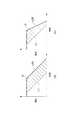
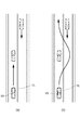
なお、制限操作量が緩く設定された場合であっても、自車両の安全度は維持又は向上され、減少されるものではない。この点について、図3〜5の例を参照して説明する。最初に、制限操作量が緩く設定された場合であっても、自車両の安全度が維持される点について説明する。図3は、自車両V0が前方に車線減少を認知し、車線変更を実施しようとする状況を示している。自車両V0が車線変更を行うにあたり、車線変更時又は車線変更後に前方車両がブレーキ操作を行うことを考慮して、適切な車間距離を維持しつつ車線変更を行う必要がある。ここで、制限操作量を緩和した場合には、自車両の安全度を維持したまま必要とされる車間距離を短くすることが可能となる。この理由を、図4を用いて説明する。図4の鎖線L1は、先行車の時系列の速度変化を示し、実線L2A又L2Bは自車両の時系列の速度変化を示している。鎖線L1と実線L2A又L2Bとで囲まれる領域Dの面積が先行車両と自車両との衝突を回避するのに必要な車間距離である。制限操作量を緩和し、より強いブレーキ操作が可能になると、図4(b)に示すように、図4(a)と比較して必要な車間距離を短くすることができる。 Even when the limited operation amount is set to be loose, the safety level of the host vehicle is maintained or improved and is not reduced. This point will be described with reference to examples of FIGS. First, the point that the safety level of the host vehicle is maintained even when the limited operation amount is set to be loose will be described. FIG. 3 shows a situation in which the host vehicle V0 recognizes a lane decrease ahead and attempts to change lanes. When the host vehicle V0 changes the lane, it is necessary to change the lane while maintaining an appropriate inter-vehicle distance in consideration that the preceding vehicle performs a brake operation when changing the lane or after changing the lane. Here, when the restriction operation amount is relaxed, the required inter-vehicle distance can be shortened while maintaining the safety level of the host vehicle. The reason for this will be described with reference to FIG. A chain line L1 in FIG. 4 indicates a time-series speed change of the preceding vehicle, and a solid line L2A or L2B indicates a time-series speed change of the host vehicle. The area of the region D surrounded by the chain line L1 and the solid line L2A or L2B is an inter-vehicle distance necessary for avoiding a collision between the preceding vehicle and the host vehicle. When the limit operation amount is relaxed and a stronger brake operation is possible, the required inter-vehicle distance can be shortened as compared with FIG. 4A, as shown in FIG.
次に、制限操作量が緩く設定された場合であっても、安全性が向上する点を説明する。同一の車間距離という条件においては制限操作量を変更することにより、安全性を向上することが可能である。図5の例を参照して説明する。上述のように、車線変更は適切な車間距離を維持しつつ行う必要がある。図5(a)は、標準的な制限操作量による動作では、先行車までの車間距離が短いため安全な車線変更が実施できない状況を示している。ここで、制限操作量が緩和されるとする。例えば、通常の制限操作量として、横Gの最大を0.2G、最大操舵速度を200deg/secとすると、横Gの最大を0.3G、最大操舵速度を300deg/secへ緩和されたものとする。この場合、図5(b)で示すように、車線変更が完了するまでの時間を短縮することができる。すなわち、車線変更に必要な車間距離を短縮することが可能となるので、目的地到着時間の短縮等も実現しつつ、安全性を確保することができる。さらに、緩やかに車線変更を行う場合と比較して、車線変更を素早く実施することにより、自車両V0は、後続車両に対して車線変更の意志を的確に伝えることができる。このように、制限操作量の緩和は、同一の車間距離という条件においては安全性を向上することができる場合がある。 Next, the point that safety is improved even when the limited operation amount is set loosely will be described. Under the condition of the same inter-vehicle distance, it is possible to improve safety by changing the limit operation amount. This will be described with reference to the example of FIG. As described above, it is necessary to change the lane while maintaining an appropriate inter-vehicle distance. FIG. 5 (a) shows a situation in which a safe lane change cannot be performed in an operation with a standard limited operation amount because the inter-vehicle distance to the preceding vehicle is short. Here, it is assumed that the limited operation amount is relaxed. For example, if the maximum amount of lateral G is 0.2 G and the maximum steering speed is 200 deg / sec, the maximum amount of lateral G is relaxed to 0.3 G and the maximum steering speed is 300 deg / sec. To do. In this case, as shown in FIG. 5B, the time until the lane change is completed can be shortened. That is, since it is possible to reduce the inter-vehicle distance required for changing the lane, it is possible to ensure safety while realizing a reduction in destination arrival time and the like. Furthermore, the host vehicle V0 can accurately convey the intention of the lane change to the following vehicle by performing the lane change quickly as compared with the case where the lane change is gently performed. As described above, the relaxation of the limited operation amount may be able to improve the safety under the condition of the same inter-vehicle distance.
図1の説明に戻り、ECU3には、表示装置21、スピーカ22、アクチュエータ23が接続されている。表示装置21は、車両内に設置されるディスプレイであり、走行支援ECU3から出力される走行支援信号に応じて各種情報を表示し、運転者に報知する。スピーカ22は、走行支援ECU3からの走行支援信号に応じて所定の音声を出力する。このように、表示装置21及びスピーカ22は、HMI(Human Machine Interface)として画面表示及び音声出力を行う。
Returning to the description of FIG. 1, a
アクチュエータ23は、走行支援ECU3から出力される走行支援信号に基づいて、ドライバーの運転操作に介入して、自車両のブレーキやアクセルを駆動させるブレーキアクチュエータやアクセルアクチュエータである。
The
次に、本実施形態に係る走行支援装置の動作について説明する。図6は、本実施形態に係る走行支援装置の動作を示すフローチャートである。図6に示す一連の走行支援処理は、例えば走行支援ECU3において予め設定された所定周期で繰り返し実行される。なお、以下では制限操作量として標準制限操作量が予め設定されているものとする。
Next, the operation of the driving support apparatus according to this embodiment will be described. FIG. 6 is a flowchart showing the operation of the driving support apparatus according to this embodiment. A series of driving support processes shown in FIG. 6 are repeatedly executed at a predetermined cycle set in advance in, for example, the driving
まず、走行支援が開始されると、自車両状態取得部31は、走行情報を取得する(S11)。自車両状態取得部31は、走行情報として、少なくとも車輪速センサ11の出力結果に基づいて自車両の車速を取得する。
First, when driving support is started, the host vehicle
次に、履歴保存部32は、S11の処理で取得された自車両の車速の履歴を所定時間にわたり保存する(S12)。そして、効率値算出部33は、履歴保存部32により保存されている自車両の車速の履歴を読み出し、読み出された車速の履歴に基づいて効率値を算出する(S13)。効率値算出部33の効率値算出方法について、2つの方法を例として以下に示す。
Next, the
第1の方法は、自車両が低速で走行している時間に応じて効率値を決定するものである。この場合、信号待ちの場合にも効率値が低下することになるので、自車両が低速(例えば5km/h以下)になってから所定時間(例えば1分間)効率値を低下させないようにすることが好ましい。 The first method is to determine the efficiency value according to the time during which the host vehicle is traveling at a low speed. In this case, since the efficiency value also decreases when waiting for a signal, the efficiency value should not be decreased for a predetermined time (for example, 1 minute) after the host vehicle becomes low speed (for example, 5 km / h or less). Is preferred.
第2の方法は、自車両の平均速度に基づいて効率値を決定するものである。この方法では、履歴保存部32により保存される自車両の車速の履歴を、例えば直近の5分間、5〜10分前、10〜15分前、15〜20分前のように時系列に4分割し、それぞれの範囲における平均車速v0,v1,v2,v3を求める。続いて、下記の式(1)に示すように平均車速v0とv0,v1,v2の平均値との差分を求める。
d=v0−(v1+v2+v3)/3 (1)
差分dが0以上であれば差分dの値に応じて効率値を増加させる。一方、差分dが0未満であれば差分dの値に応じて効率値を減少させる。また、効率値を増減させるまでに所定の時間のマージンを設けることで、効率値を安定させることができる。
The second method is to determine the efficiency value based on the average speed of the host vehicle. In this method, the vehicle speed history of the host vehicle stored by the
d = v0− (v1 + v2 + v3) / 3 (1)
If the difference d is 0 or more, the efficiency value is increased according to the value of the difference d. On the other hand, if the difference d is less than 0, the efficiency value is decreased according to the value of the difference d. Moreover, the efficiency value can be stabilized by providing a margin for a predetermined time until the efficiency value is increased or decreased.
続いて、制限操作量設定部34は、S13の処理で算出された効率値が低下しているか否かを判断する(S14)。制限操作量設定部34は、効率値が低下していると判断した場合には、効率値に応じて制限操作量を緩和する(S15)。一方、制限操作量設定部34は、効率値が低下していないと判断した場合には、制限操作量は変更しない。以上で、図6に示す一連の処理を終了し、制限操作量を用いて走行支援が実行される。
Subsequently, the limited operation
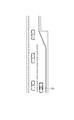
図6に示す制御処理を実行することにより、効率値算出部33により自車両の効率値が算出され、制限操作量設定部34により効率値が低いほど制約条件が緩和される。このように、自車両にとっての効率値を勘案して、自車両に許される行動の幅を広げることができる。これにより、車両の行動が、固定された制限値の上限に縛られることがないため、運転者又は乗員が多少乗り心地を犠牲にしても旅行時間等を優先させたいと感じる場面において、適切な運転支援が行われ、結果として運転者又は乗員に違和感を与えることを回避できる。例えば、図7に示す状況を用いて具体的に説明する。図7は、自車両V0が交差点を右折するために停車している場面を示している。対向車両の交通流が大きく、自車両が安全に右折するために必要な車間距離がとれないため、自車両は右折が可能な車間距離がとれるまで交差点内で停止しているものとする。この場合、障害物がない環境下、すなわち対向車両が存在しない場合の行動に比較して、現在の状況では自車両V0の車速がほぼ0となる停止状態であるため効率値が低下する。そうすると、制限操作量設定部34により制限操作量が緩和され、例えば、自車両V0が選択できる前後方向加速度と横加速度の制限が緩和される。例えば、通常の発進加速度の最大を0.1G、横Gの最大を0.2Gと設定していた場合には、発進加速度の最大を0.15G、横Gの最大を0.3Gと設定する。これにより、右折に必要となる車間距離が短縮されるので、右折可能な機会(タイミング)を増やすことができる。結果、早期に右折を行うことが可能になる。また、右折後に通常通り走行を行っている際には、効率値が0付近に戻るため、急激な操作が実施されずに快適性を維持した走行支援が実施される。
By executing the control process shown in FIG. 6, the efficiency
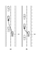
なお、走行支援における制限操作量を制約条件とし、効率値に応じて制限操作量を緩和する例を説明したが、制限操作量以外の制約条件を緩和するようにしてもよい。例えば、原則及び例外が存在する交通ルールにおいて、通常の制約条件では原則の交通ルール、緩和した制約条件では例外の交通ルールというように、効率値に応じて適用される交通ルールを変更するようにしてもよい。具体的な例を、図8を参照して説明する。 In addition, although the example in which the limited operation amount in the driving support is used as the constraint condition and the limited operation amount is relaxed according to the efficiency value has been described, the constraint conditions other than the limit operation amount may be relaxed. For example, in traffic rules that have principles and exceptions, change the traffic rules to be applied according to the efficiency value, such as the rule traffic rules for normal constraints and the exception rules for relaxed constraints. May be. A specific example will be described with reference to FIG.
図8(a)は自車両V0が片側一車線の追い越し禁止の道路を走行している状況を示している。自車両V0の前方には、駐車車両が存在している。自車両が黄色実線YLをはみ出さずに駐車車両を追い越すことができない場合、追い越し禁止の原則の交通ルールのみを遵守すると自車両V0は進行することができずに、効率が低下することとなる。ここで、交通ルールでは駐車車両の追い越しは、追い越しではなく障害物回避として扱われることになるため、図8(b)のように黄色実線YLをはみ出しても例外的に交通ルール違反にはならない。そこで本発明に係る走行支援装置は、交通ルールの変化を検出し、効率値の低下に応じて走行支援装置に適用される交通ルールを変更させることにより、効率の良い走行支援を行うようにすることもできる。 FIG. 8A shows a situation in which the host vehicle V0 is traveling on a one-lane lane overtaking prohibited road. A parked vehicle is present in front of the host vehicle V0. If the vehicle cannot overtake the parked vehicle without protruding the yellow solid line YL, the vehicle V0 cannot proceed and the efficiency decreases if only the traffic rules of the principle of overtaking are observed. . Here, in the traffic rule, overtaking a parked vehicle is handled as obstacle avoidance rather than overtaking. Therefore, even if the yellow solid line YL protrudes as shown in FIG. . Therefore, the driving support device according to the present invention performs efficient driving support by detecting a change in the traffic rule and changing the traffic rule applied to the driving support device in accordance with a decrease in the efficiency value. You can also
以上、第1実施形態に係る走行支援装置10によれば、効率値算出部33により障害物がない環境下における自車両の行動に対する遅延度を示す効率値が算出され、制限操作量設定部34により効率値が低いほど制約条件が緩和される。このように、効率値が低く、走行支援を実行する必要性が高い場合には、走行支援装置10に許される行動の幅を広げることにより、乗り心地等の快適性を常に追求するのではなく、状況に応じて目的地到着時間の短縮等の利便性が著しく損なわれることを回避することができる。よって、運転者又は乗員に与える違和感を低減することが可能となる。
As described above, according to the driving
また、第1実施形態に係る走行支援装置10によれば、制限操作量設定部34により効率値が低いほど自車両の操作量に関する条件が緩和された上で、走行支援が実行される。このように、効率値が低下している場合に、走行支援装置10に許される操作量の幅を広げることにより、運転者又は乗員に与える違和感を低減することができる。
Moreover, according to the driving
(第2実施形態)
次に、本発明の第2実施形態について説明する。第2実施形態に係る走行支援装置20は、第1実施形態に係る走行支援装置10とほぼ同様に構成され、通信装置12、道路情報DB41及び道路情報取得部42を更に備える点が相違する。以下では、説明理解の容易性を考慮して、第1実施形態との相違点を中心に説明し、重複する説明は省略する。
(Second Embodiment)
Next, a second embodiment of the present invention will be described. The driving
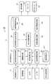
図9は、本発明の第2実施形態に係る走行支援装置を示すブロック図である。図9に示すように、走行支援装置20は、第1実施形態に係る走行支援装置10の構成に、通信装置12、道路情報DB41及び道路情報取得部42を更に備える構成とされている。
FIG. 9 is a block diagram showing a driving assistance apparatus according to the second embodiment of the present invention. As illustrated in FIG. 9, the driving
通信装置12は、例えば車両に搭載される無線通信装置であり、車車間通信や路車間通信により自車両周辺の道路情報を取得する。通信装置12は、車載の無線通信装置に限られるものではなく、携帯電話でもよい。
The
道路情報DB41は、自車両周辺の道路における道路情報を格納している。道路情報には、時間にとともに変化することのない静的な道路情報と、時間とともに刻々と変化する動的な道路情報が存在する。静的な道路情報としては、例えば道路形状(交差点、道路幅、車線数、車線幅、道路の曲率、歩道の有無、境界線(中央線、白線又は黄色線)の有無、又は、縁石の有無等)、や交通ルール(制限速度、信号の有無、一時停止線又は踏切等)がある。一方、動的な情報としては道路の混雑状況(時間帯での区分け、又は車線毎の区分け)等がある。静的な情報は道路情報DB41に予め格納されており、動的な情報は通信装置12により逐次更新される。また、通信装置12によらなくても、日常的又は特定の時間帯に混雑している道路の場合には、予め道路情報DB41に混雑状況を格納しておくことで、通信装置12が利用できない場合にも混雑状況を取得できるようにしてもよい。
The
道路情報取得部42は、道路情報DB41を参照して自車両周辺の道路情報を取得し、効率値算出部33へ出力する。効率値算出部33は、履歴保存部32により出力される自車両の走行履歴と道路情報取得部42により出力される道路情報とに基づいて効率値を算出する。本実施形態に係る効率値算出部33は、以下の方法で効率値を算出することができる。
The road
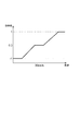
効率値算出部33は、自車両の車速と法定速度との差分に基づいて効率値を算出する。具体的に図を用いて説明する。図10は、効率値の車速依存性を示すグラフであり、横軸が車速、縦軸が効率値である。なお、図10では、法定速度が30km/hの場合を示している。図10に示すように、自車両が法定速度である30km/hで走行している場合には、効率値を0にする。自車両の車速が30km/hよりも遅い場合には、その車速に応じて効率値を低下させる。一方、自車両の車速が30km/hよりも速い場合には、その車速に応じて効率値を向上させる。また、法定速度を基準とした所定範囲の速度域では、効率値が変化しないようなマージンを設けておくことにより、効率値を安定させることができる。
The
また、効率値算出部33は、第1実施形態で示した自車両の平均速度の履歴を参照するとともに、道路形状と交通ルールに基づいて効率値を向上させるようにしてもよい。例えば、信号機がある交差点においては、信号表示が赤である場合には自車両の効率が低下しているとはいえないため、路車間通信等により信号表示の情報を取得し、信号表示が赤の場合には平均車速が低下していても効率値が低下しないようにしてもよい。例えば、交通状況に応じて効率値を正に補正することで、効率値を低下しないようにすることができる。
Further, the efficiency
また、自車両が曲率の大きい道路を走行している場合には、曲率が小さい道路を走行する場合と比較して平均車速が低下するが、このような走行は効率が低下しているとはいえないものである。そのため、効率値算出部33は、自車両が曲率の大きな道路を走行している場合には、効率値を低下させないようにしてもよい。また、交差点や道路幅が狭い道路、中央線のない道路についても同様に、効率値を低下させないようにしてもよい。例えば、道路形状等に応じて効率値を正に補正することで、効率値を低下しないようにすることができる。
In addition, when the vehicle is traveling on a road with a large curvature, the average vehicle speed is lower than when traveling on a road with a small curvature, but such traveling is less efficient. It can't be said. Therefore, the efficiency
更に、効率値算出部33は、自車両の走行履歴に加えて、自車両が走行している道路が混雑しているか否かに基づいて効率値を算出してもよい。この場合、自車両が走行している道路が混雑しているという情報を取得した場合には、効率値を低下させる車速の閾値を低下させて効率値を算出する。また、効率値算出部33は、自車両が混雑情報を取得した時点で効率値を低下させるようにしてもよい。また、地形的あるいは道路形状的にみて混雑しやすい道路であるという情報を利用して効率値を低下させるようにしてもよい。例えば、交通状況に応じて効率値を負に補正することで、効率値を低下させることができる。
Further, the efficiency
また、効率値算出部33は、自車両の走行履歴に加えて、自車両が交差点に近づいているか否かに基づいて効率値を算出してもよい。この場合、自車両が交差点に接近した場合には、効率値を低下させる車速の閾値を低下させて効率値を算出する。また、効率値算出部33は、自車両が交差点に接近した時点で効率値を低下させるようにしてもよい。
Further, the efficiency
本実施形態に係る走行支援装置20の動作は、図6に示す第1実施形態に係る走行支援装置10の動作と同様であるため、再度の説明は省略する。ただし、第1実施形態ではS11において、走行情報として自車両の車速を取得しているが、本実施形態に係る走行支援装置20では、自車両の車速に加えて道路情報を取得する点で第1実施形態と相違する。このため、道路状況に基づいて効率値を算出することができる。
The operation of the driving
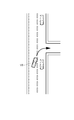
本実施形態が適用される状況を具体的な例を用いて説明する。図11は自車両V0が片側2車線道路に置いて車線変更をしようとしている場面を示している。走行支援装置は、運転者又は乗員の快適性の観点から自車両の制限操作量を例えば横加速度0.2G以下に収めるように設定しているものとする。自車両は、制限操作量に基づいて車線変更をするための十分な車間距離がない場合にも、車線変更を実施するまで暫く待つことができればいずれ車間距離が確保されて車線変更が可能になる。しかしながら、図10(a)に示すように、自車両の前方で車線が減少する場合には、車線変更を行わずに待っていると、車線減少箇所の手前で停車する必要があり、効率が低下してしまうことになる。そこで、本実施形態は、道路情報取得部42により自車両前方の車線減少を取得することにより、将来の効率値の低下を予測し、効率値を低下させることもできる。この場合、制限操作量を例えば横加速度0.3Gに緩和することにより、図10(b)に示すように、車線変更を行うことが可能であり、効率のよい走行支援を実行することが可能になる。
The situation to which this embodiment is applied will be described using a specific example. FIG. 11 shows a scene where the host vehicle V0 is about to change lanes on a two-lane road on one side. It is assumed that the driving support device is set so that the limited operation amount of the host vehicle is within a lateral acceleration of 0.2 G or less, for example, from the viewpoint of driver or passenger comfort. Even if there is not enough inter-vehicle distance to change lanes based on the limit operation amount, the own vehicle can wait for a while until lane change is performed, and the inter-vehicle distance will be secured and it will be possible to change lanes. . However, as shown in FIG. 10 (a), when the lane decreases in front of the host vehicle, if waiting without changing the lane, it is necessary to stop before the lane decreasing point, and the efficiency is improved. It will fall. Therefore, in the present embodiment, by acquiring a lane decrease ahead of the host vehicle by the road
以上、第2実施形態に係る走行支援装置20によれば、第1実施形態に係る走行支援装置10と同様の作用効果を奏する。また、第2実施形態に係る走行支援装置20によれば、自車両の車速の履歴と自車両周辺の道路状況とに基づいて効率値算出部33により効率値が算出され、制限操作量設定部34により効率値が低いほど制約条件が緩和される。このように、自車両の車速の履歴と自車両周辺の道路状況とに基づいて効率値が算出されることにより、道路状況に応じて適切な効率値を算出することができる。
As mentioned above, according to the driving
(第3実施形態)
次に、本発明の第3実施形態について説明する。第3実施形態に係る走行支援装置30は、第1実施形態に係る走行支援装置10とほぼ同様に構成され、カメラ13、レーダ14及び車外環境取得部43を更に備える点が相違する。以下では、説明理解の容易性を考慮して、第1実施形態との相違点を中心に説明し、重複する説明は省略する。
(Third embodiment)
Next, a third embodiment of the present invention will be described. The driving
図12は、本発明の第3実施形態に係る走行支援装置を示すブロック図である。図12に示すように、走行支援装置30は、第1実施形態に係る走行支援装置10の構成に、カメラ13、レーダ14及び車外環境取得部43を更に備える構成とされている。
FIG. 12 is a block diagram showing a travel support apparatus according to the third embodiment of the present invention. As illustrated in FIG. 12, the driving
カメラ13は、自車両の周辺を撮像する装置である。自車両の周辺とは、少なくとも前方であり、必要に応じて側方、後方も撮像する。カメラ13は、自車両の周辺を撮像し、その撮像画像のデータを画像信号として走行支援ECU3に送信する。
The
レーダ14は、自車両の周辺の物体を検出するための装置である。自車両の周辺とは、少なくとも前方であり、必要に応じて側方、後方の物体も検出する。レーダ14としては、例えば、レーザレーダ、ミリ波レーダがある。レーダ14では、電磁波を水平面内でスキャンしながら送信し、物体に反射して戻ってくる反射波を受信し、その送受信に関する情報を検出する。そして、レーダ14は、その検出した送受信情報をレーダ信号として走行支援ECU3に送信する。
The
車外環境取得部43は、カメラ13による画像情報及びレーダ14によるレーダ情報に基づいて自車両周辺の車外環境情報を取得する。車外環境情報とは、例えば先行/後続車両の有無、先行/後続車両までの距離、先行/後続車両の速度、前方/後方の混雑状況、対向車の有無、対向車までの距離、対向車の数等である。
The vehicle exterior
効率値算出部33は、履歴保存部32に保存される自車両の走行履歴と車外環境取得部43により取得される車外環境情報とに基づいて効率値を算出する。本実施形態に係る効率値算出部33は、第1実施形態で説明した効率値算出方法に追加して、車外環境情報を用いて効率値を算出することにより、より適切な効率値を得るものである。以下に自車両の走行履歴に加えて車外環境情報を用いて適切な効率値を算出する例を示す。
The efficiency
例えば、効率値算出部33は、自車両の走行履歴に加えて自車両周辺の交通流に基づいて効率値を算出する。自車両周辺の交通流が停止する傾向にある場合には、自車両の速度も遅くなることは自然であり、このような状況において自車両の速度が低下する際に効率値を低下させることは適切でない。そのため、車外環境取得部43は、カメラ13及びレーダ14を用いて前後車両との車間距離及び相対速度を取得して交通流の状態を取得する。効率値算出部33は、交通流が停止する傾向にあると判断した場合には、自車両の速度が低下した場合にも効率値を低下させないようにする。一方、自車両周辺の交通流に停止する傾向がなく、自車両の前方に先行車両の存在を認知した場合には効率値を低下させるようにしてもよい。このような状況では、効率値を低下させ、制限操作量を緩和することにより先行車両の急ブレーキに適切に対応することができるようになる。
For example, the efficiency
本実施形態に係る走行支援装置の動作は、図6に示す第1実施形態に係る走行支援装置10の動作と同様であるため、再度の説明は省略する。ただし、第1実施形態ではS11において、走行情報を取得しているが、本実施形態に係る走行支援装置30では、走行情報に加えて車外環境情報を取得する点で第1実施形態と相違する。このため、車外環境情報に基づいて効率値を算出することができる。
The operation of the driving support apparatus according to the present embodiment is the same as the operation of the driving
以上、第3実施形態に係る走行支援装置30によれば、第1実施形態に係る走行支援装置10と同様の作用効果を奏する。また、第3実施形態に係る走行支援装置30によれば、自車両の走行履歴及び自車両周辺の車外環境情報に基づいて効率値算出部33により効率値が算出され、制限操作量設定部34により効率値が低いほど制限操作量が緩和される。このように、自車両の車速の履歴と自車両周辺の車外環境情報とに基づいて効率値が算出されることにより、車外環境に応じた適切な効率値を算出することができる。
As mentioned above, according to the driving
(第4実施形態)
次に、本発明の第4実施形態について説明する。第4実施形態に係る走行支援装置40は、第2実施形態に係る走行支援装置20とほぼ同様に構成され、目的地設定部15及び目標経路計画部44を更に備える点が相違する。以下では、説明理解の容易性を考慮して、第2実施形態との相違点を中心に説明し、重複する説明は省略する。
(Fourth embodiment)
Next, a fourth embodiment of the present invention will be described. The
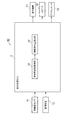
図13は、本発明の第4実施形態に係る走行支援装置を示すブロック図である。図13に示すように、走行支援装置40は、第2実施形態に係る走行支援装置20の構成に、目的地設定部15及び目標経路計画部44を更に備える構成とされている。
FIG. 13 is a block diagram showing a driving assistance apparatus according to the fourth embodiment of the present invention. As illustrated in FIG. 13, the driving
目的地設定部15は、例えばカーナビゲーションシステムのユーザーインターフェイスであり、利用者の目的地を設定するための手段である。目標経路計画部44は、自車両の現在位置から目的地設定部15によって設定された目的地までの目標経路を生成する装置である。この目標経路は、現在位置を出発し目的地に到着するまでに走行する道路及び車線情報を含み、その経路を移動することで交通ルール(はみ出し禁止、右左折禁止、進入禁止等)を違反しない経路である。すなわち、目標経路計画部44により生成される目標経路は、車両、歩行者、落下物等の自車両に干渉する障害物が存在する場合を除き、交通ルールが定めた速度以下で移動することで交通ルールを遵守しながら安全に目的地まで到着することができる経路である。
The
効率値算出部33は、履歴保存部32に保存される自車両の走行履歴、道路情報取得部42により取得される道路情報及び目標経路計画部44により生成される目標経路に基づいて効率値を算出する。本実施形態に係る効率値算出部33は、第2実施形態で説明した効率値算出方法に加えて、目標経路を用いて効率値を算出することにより、より適切な効率値を得ることができる。以下に自車両の走行履歴、道路情報に加えて目標経路を用いて適切な効率値を算出する例を示す。
The efficiency
例えば、効率値算出部33は、自車両が将来走行する予定の経路の混雑状況に基づいて効率値を算出する。そのために、目標経路計画部44は、目的地設定部15から目的地を取得し目標経路を生成する。道路情報取得部42は、通信装置12及び道路情報DB41を参照して、目標経路の道路の混雑状況を取得する。効率値算出部33は、履歴保存部32に保存されている自車両の走行履歴と目標経路の道路の混雑状況とを参照し、自車両が将来走行する道路が混雑している場合には、効率値を低下させる。
For example, the efficiency
また、効率値算出部33は、目標経路及び道路情報により自車両が将来交差点を通過することを認識した場合には効率値を低下させるようにしてもよい。また、同様の方法で自車両が将来車線の減少がある道路を走行することを認識した場合に効率値を低下させるようにしてもよい。
Further, the efficiency
本実施形態に係る走行支援装置の動作は、図6に示す第1実施形態に係る走行支援装置10の動作と同様であるため、再度の説明は省略する。ただし、第1実施形態ではS11において、走行情報として自車両の走行情報を取得しているが、本実施形態に係る走行支援装置40では、走行情報の取得に加えて道路情報の取得及び目標経路の生成を行う点で第1実施形態と相違する。このため、目標経路に基づいて効率値を算出することができる。
The operation of the driving support apparatus according to the present embodiment is the same as the operation of the driving
以上、第4実施形態に係る走行支援装置40によれば、第2実施形態に係る走行支援装置20と同様の作用効果を奏する。また、第4実施形態に係る走行支援装置40によれば、自車両の走行履歴、道路情報及び目標経路に基づいて効率値算出部33により効率値が算出され、制限操作量設定部34により効率値が低いほど制約条件が緩和される。このように、自車両の走行履歴、道路情報及び目標経路に基づいて効率値を算出することで、将来自車両が走行する道路状況に応じた適切な効率値を算出することができる。
As mentioned above, according to the driving
(第5実施形態)
次に、本発明の第5実施形態について説明する。第5実施形態に係る走行支援装置50は、第4実施形態に係る走行支援装置40とほぼ同様に構成され、カメラ13、レーダ14及び車外環境取得部43を更に備える点が相違する。以下では、説明理解の容易性を考慮して、第4実施形態との相違点を中心に説明し、重複する説明は省略する。
(Fifth embodiment)
Next, a fifth embodiment of the present invention will be described. The driving
図14は、本発明の第5実施形態に係る走行支援装置を示すブロック図である。図14に示すように、走行支援装置50は、第4実施形態に係る走行支援装置40の構成に、カメラ13、レーダ14及び車外環境取得部43を更に備える構成とされている。なお、カメラ13、レーダ14及び車外環境取得部43は、第3実施形態で説明したものと同一である。
FIG. 14 is a block diagram showing a driving support apparatus according to the fifth embodiment of the present invention. As illustrated in FIG. 14, the driving
効率値算出部33は、自車両の走行履歴、道路情報、目標経路及び車外環境情報に基づいて効率値を算出する。効率値算出部33は、第4実施形態で説明した効率値算出方法に加えて、車外環境情報を用いて効率値を算出することにより、より適切な効率値を得るものである。以下に自車両の走行履歴、道路情報、目標経路及び車外環境情報を用いて適切な効率値を算出する例を示す。
The efficiency
例えば、効率値算出部33は、自車両の走行履歴、道路情報、目標経路及び周辺車両の存在に基づいて効率値を算出する。第4実施形態では目標経路及び道路情報により自車両が将来交差点を通過することを認識した場合には効率値を低下させることを説明した。しかしながら、将来自車両が将来交差点を通過する場合でも、周辺車両が交差点において自車両に干渉しないのであれば効率値を低下させることは適切でない。そこで、本実施形態に係る走行支援装置50では、目標経路が交差点を通過するものであった場合に、カメラ13又はレーダ14により自車両周辺の車両を検出し、周辺の他車両が自車両に干渉しない場合には、効率値を低下させないようにする。このように、交差点等の効率値が低下する状況においても車外環境に基づいて、効率値が低下しないと考えられる状況では効率値を下げないことで、不必要に効率値が低下することを防止することができる。
For example, the efficiency
また、目標経路で右折が必要とされる交差点において、対向車両が多いために右折待ちが発生していることを車外環境取得部43により取得した場合には、効率値を低下させるようにしてもよい。
In addition, when the vehicle exterior
本実施形態に係る走行支援装置の動作は、図6に示す第1実施形態に係る走行支援装置10の動作と同様であるため、再度の説明は省略する。ただし、第1実施形態ではS11において、走行情報として自車両の走行情報を取得しているが、本実施形態に係る走行支援装置50では、走行情報の取得に加えて道路情報の取得、車外環境情報の取得及び目標経路の生成を行う点で第1実施形態と相違する。このため、道路情報及び目標経路に基づいて効率値を算出することができる。
The operation of the driving support apparatus according to the present embodiment is the same as the operation of the driving
以上、第5実施形態に係る走行支援装置50によれば、第4実施形態に係る走行支援装置40と同様の作用効果を奏する。また、第5実施形態に係る走行支援装置50によれば、自車両の走行履歴、道路情報、目標経路及び車外環境に基づいて効率値算出部33により効率値が算出され、制限操作量設定部34により効率値が低いほど制約条件が緩和される。このように、自車両の走行履歴、自車両周辺の道路情報及び目標経路に基づいて効率値が算出されることにより、将来自車両が通過する経路の道路状況を考慮した適切な効率値を算出することができる。そのため、自車両の効率値が実際に低下するよりも早いタイミングで走行支援を実施することが可能となるので、運転者又は乗員に与える違和感を低減することができる。
As mentioned above, according to the driving
(第6実施形態)
次に、本発明の第6実施形態について説明する。第6実施形態に係る走行支援装置60は、第5実施形態に係る走行支援装置50とほぼ同様に構成され、車外環境予測部45を更に備える点が相違する。以下では、説明理解の容易性を考慮して、第5実施形態との相違点を中心に説明し、重複する説明は省略する。
(Sixth embodiment)
Next, a sixth embodiment of the present invention will be described. The driving
図15は、本発明の第6実施形態に係る走行支援装置を示すブロック図である。図15に示すように、走行支援装置60は、第5実施形態に係る走行支援装置50の構成に、車外環境予測部45を更に備える構成とされている。なお、カメラ13、レーダ14及び車外環境取得部43は、第3実施形態で説明したものと同一である。
FIG. 15 is a block diagram showing a driving support apparatus according to the sixth embodiment of the present invention. As illustrated in FIG. 15, the driving
車外環境予測部45は、将来の車外環境を予測する手段である。車外環境予測部45は、車外環境取得部43により取得された車両や歩行者等の障害物と、道路情報取得部42により取得された道路情報から、当該障害物の将来の挙動を予測する。この障害物の将来の挙動を予測は従来公知の方法を適用して行うことができる。
The vehicle exterior
本実施形態の効率値算出部33は、自車両の走行履歴、道路情報、目標経路及び予測される将来の車外環境に基づいて効率値を算出する。自車両の走行履歴、道路情報、目標経路及び予測される将来の車外環境に基づいて効率値を算出する2つの方法を例として以下に示す。
The efficiency
効率値算出部33は、自車両の走行履歴、道路情報、目標経路及び予測される将来の車外環境情報に基づいて効率値を算出する。本実施形態に係る効率値算出部33は、第5実施形態で説明した効率値算出方法に加えて、車外環境予測部45により予測される将来の車外環境情報に基づいて効率値を算出することにより、より適切な効率値を得るものである。以下に予測される将来の車外環境情報に基づいて適切な効率値を算出する例を示す。
The efficiency
例えば、効率値算出部33は、自車両の走行履歴、道路情報、目標経路に加えて将来予測される周辺車両の挙動に基づいて効率値を算出する。例えば、自車両と対向車両が同じ交差点に進入しようとしている状況において、車外環境予測部45は対向車両が自車両よりも交差点から遠い場所を走行しており、且つ、自車両が交差点で停止した場合に停車時間が長いことを予測した場合には、自車両の効率値を低下させる。このよう、効率値を低下させ、制限操作量を緩和することにより交差点内で停止することなく右折を実行することができるようになる。
For example, the efficiency
本実施形態に係る走行支援装置の動作は、図6に示す第1実施形態に係る走行支援装置10の動作と同様であるため、再度の説明は省略する。ただし、第1実施形態ではS11において、走行情報として自車両の車速を取得しているが、本実施形態に係る走行支援装置60では、走行情報の取得に加えて道路情報の取得、将来の車外環境情報の予測及び目標経路の生成を行う点で第1実施形態と相違する。このため、道路情報、予測された車外環境情報及び目標経路に基づいて効率値を算出することができる。
The operation of the driving support apparatus according to the present embodiment is the same as the operation of the driving
以上、第6実施形態に係る走行支援装置60によれば、第5実施形態に係る走行支援装置50と同様の作用効果を奏する。また、第6実施形態に係る走行支援装置60によれば、自車両の走行履歴、道路情報、目標経路及び予測される将来の車外環境に基づいて効率値算出部33により効率値が算出され、制限操作量設定部34により効率値が低いほど制約条件が緩和される。このように、自車両の走行履歴、自車両周辺の道路情報、目標経路及び予測される将来の車外環境に基づいて効率値が算出されることにより、将来の車外環境情報に応じた適切な効率値を算出することができる。そのため、自車両の効率値が実際に低下するよりも早いタイミングで走行支援を実施することが可能となるため、運転者又は乗員に与える違和感を低減することができる。
As mentioned above, according to the driving
(第7実施形態)
次に、本発明の第7実施形態について説明する。図16は、本発明の第7実施形態に係る走行支援装置を示すブロック図である。本実施形態に係る走行支援装置70における走行支援ECU3は自車両状態取得部31、制限操作量設定部34及び標準制限操作量DB36のみを備えている。第1〜6実施形態では、効率値算出部33が効率値を算出し、制限操作量設定部34が、効率値を参照して制限操作量を設定しているが、本実施形態に係る走行支援装置70では、予め自車両状態に応じた制限操作量が標準制限操作量DB36に格納されている。制限操作量設定部34は、標準制限操作量DB36を参照し、自車両の位置や速度に対応する制限操作量を読み出すことで、制限操作量を設定する。
(Seventh embodiment)
Next, a seventh embodiment of the present invention will be described. FIG. 16 is a block diagram showing a driving support apparatus according to the seventh embodiment of the present invention. The
また、図17は、本実施形態の変形例を示している。この変形例に係る走行支援装置80では、通信装置12を介して自車両の位置や速度に対応する制限操作量を読み出すことで制限操作量を自車両の制限操作量を設定する。通信装置12は、例えば、VICSのように、特定の場所を通過した際に自車両の走行状態を送信するとともに、対応する制限操作量を受信してもよい。
FIG. 17 shows a modification of the present embodiment. In the
図18は、上述した第1〜6実施形態に示す走行支援装置における制限操作量の取得処理を示すフローチャートである。走行支援の処理が開始されると、まず自車両情報が取得できたか否かが判断される(S21)。自車両情報が取得できない場合には、一連の走行支援処理が終了する。一方、自車両情報が取得されると目標経路があるか否かが判断される(S22)。目標経路が取得されている場合には、目標フラグがONに設定される(S24)とともに道路情報フラグがONに設定される(S25)。一方、目標経路が取得されていない場合には、目標経路フラグがOFFに設定される(S26)。S26において目標経路フラグがOFFに設定されると、道路情報が取得されているか否かが判断される(S27)。道路情報が取得されている場合には道路情報がONに設定され(S28)、道路情報が取得されていない場合には道路情報フラグがOFFに設定される(S29)。 FIG. 18 is a flowchart showing a process for acquiring a limited operation amount in the travel support apparatus shown in the first to sixth embodiments. When the driving support process is started, it is first determined whether or not the own vehicle information has been acquired (S21). When the own vehicle information cannot be acquired, the series of driving support processing ends. On the other hand, when the own vehicle information is acquired, it is determined whether or not there is a target route (S22). When the target route is acquired, the target flag is set ON (S24) and the road information flag is set ON (S25). On the other hand, when the target route is not acquired, the target route flag is set to OFF (S26). If the target route flag is set to OFF in S26, it is determined whether road information is acquired (S27). When the road information is acquired, the road information is set to ON (S28), and when the road information is not acquired, the road information flag is set to OFF (S29).
S25、S28、S29のいずれかにおいて道路情報フラグがON又はOFFに設定されると、次に障害物予測結果があるか否かが判断される。障害物予測結果がある場合には、予測結果フラグがONに設定される(S31)とともに、障害物情報フラグがONに設定される(S32)。一方、障害物予測結果がない場合には、予測結果フラグがOFFに設定される(S33)。予測結果フラグがOFFに設定されると、次に障害物情報があるか否かが判断される(S34)。障害物情報があると判断された場合には障害物情報フラグがONに設定される(S35)。一方、障害物情報がないと判断された場合には、障害物情報フラグがOFFに設定される(S36)。 If the road information flag is set to ON or OFF in any of S25, S28, and S29, it is next determined whether or not there is an obstacle prediction result. If there is an obstacle prediction result, the prediction result flag is set ON (S31), and the obstacle information flag is set ON (S32). On the other hand, when there is no obstacle prediction result, the prediction result flag is set to OFF (S33). When the prediction result flag is set to OFF, it is next determined whether there is obstacle information (S34). If it is determined that there is obstacle information, the obstacle information flag is set to ON (S35). On the other hand, when it is determined that there is no obstacle information, the obstacle information flag is set to OFF (S36).
S32、S35、S36のいずれかにおいて障害物情報フラグがON又はOFFに設定されると、走行履歴があるか否かが判断される(S37)。走行履歴があると反出された場合には、走行履歴フラグがONに設定される(S38)。一方、走行履歴がない場合には走行履歴フラグがOFFに設定される(S39)。S38又はS39において走行履歴フラグがON又はOFFに設定されると、各種フラグの設定状態に基づいて効率値が計算される(S40)。その後、S40で計算された効率値に基づいて制限操作量が取得される(S41)。制限操作量が取得されると一連の制限操作量の取得処理が終了する。 When the obstacle information flag is set to ON or OFF in any of S32, S35, and S36, it is determined whether or not there is a travel history (S37). If it is rejected that there is a travel history, the travel history flag is set to ON (S38). On the other hand, if there is no travel history, the travel history flag is set to OFF (S39). When the travel history flag is set to ON or OFF in S38 or S39, the efficiency value is calculated based on the setting state of various flags (S40). Thereafter, the limited operation amount is acquired based on the efficiency value calculated in S40 (S41). When the limited operation amount is acquired, a series of processing for acquiring the limited operation amount ends.
以上、第7実施形態に係る走行支援装置70によれば、第1〜6実施形態に係る走行支援装置10〜60と同様の作用効果を奏する。
As mentioned above, according to the driving
なお、上述した各実施形態は本発明に係る走行支援装置の一例を示すものである。本発明に係る走行支援装置は、各実施形態に係る走行支援装置に限られるものではなく、各請求項に記載した要旨を変更しない範囲で、各実施形態に係る走行支援装置を変形し、又は他のものに適用したものであってもよい。 Each embodiment mentioned above shows an example of the run support device concerning the present invention. The driving support device according to the present invention is not limited to the driving support device according to each embodiment, and the driving support device according to each embodiment is modified or changed without changing the gist described in each claim, or It may be applied to other things.
例えば、上記第1〜8実施形態では、制約条件として自車両の操作量の制限を緩和することを述べたが、制約条件は制限操作量に限定されるものではなく、交通ルール等のその他の制約条件でもよい。 For example, in the first to eighth embodiments, it has been described that the restriction on the operation amount of the host vehicle is relaxed as the constraint condition. However, the constraint condition is not limited to the limit operation amount, and other traffic rules and the like can be used. It may be a constraint condition.
また、第1実施形態では、効率値が0より大きい場合には、標準制限操作量を制限操作量としているが、標準制限操作量よりも制限操作量を小さくしてもよい。このようにすることで、効率値が高い場合には、標準的な効率値の場合と比較してより快適性の高い走行支援を実行することができる。 In the first embodiment, when the efficiency value is greater than 0, the standard limited operation amount is set as the limited operation amount. However, the limited operation amount may be smaller than the standard limited operation amount. By doing in this way, when the efficiency value is high, it is possible to execute driving support with higher comfort than in the case of the standard efficiency value.
また、第1実施形態では、制限操作量設定部34が、効率値を参照して制限操作量を設定しているが、予め効率値に応じた制限操作量を標準制限操作量DB36に格納しておいてもよい。なお、本明細書における走行支援とは、運転者への注意喚起や介入制御を実施することによる運転支援のみでなく、自動運転を含むものである。よって、本発明に係る走行支援装置は、自動運転システムに搭載され、制限操作量に基づいて自動運転を行う装置として構成されてもよい。
In the first embodiment, the limit operation
3…走行支援ECU、10,20,30,40,50,60,70,80…走行支援装置、11…車輪速センサ、12…通信装置、13…カメラ、14…レーダ、15…目的地設定部、21…表示装置、22…スピーカ、23…アクチュエータ、31…自車両状態取得部、32…履歴保存部、33…効率値算出部、34…制限操作量設定部、35…走行支援制御部、36…標準制限操作量DB、41…道路情報DB、42…道路情報取得部、43…車外環境取得部、44…目標経路計画部、45…車外環境予測部。
3 ... Driving
Claims (3)
障害物がない環境下における自車両の行動に対する遅延度を示す効率値を算出する効率値算出手段と、
前記効率値が低いほど前記制約条件を緩和する制約条件変更手段と、
を備える走行支援装置。 A driving support device that supports driving of the host vehicle according to a constraint condition,
An efficiency value calculating means for calculating an efficiency value indicating a degree of delay with respect to the behavior of the host vehicle in an environment without an obstacle;
A constraint condition changing means for relaxing the constraint condition as the efficiency value is lower;
A driving support device comprising:
前記制約条件変更手段は、将来の前記効率値が低いほど前記制約条件を緩和する請求項1又は2に記載の走行支援装置。
The efficiency value calculating means predicts the future efficiency value based on environmental information around the host vehicle,
The driving support device according to claim 1, wherein the constraint condition changing unit relaxes the constraint condition as the future efficiency value is lower.
Priority Applications (1)
| Application Number | Priority Date | Filing Date | Title |
|---|---|---|---|
| JP2010268606A JP5766941B2 (en) | 2010-12-01 | 2010-12-01 | Driving support device |
Applications Claiming Priority (1)
| Application Number | Priority Date | Filing Date | Title |
|---|---|---|---|
| JP2010268606A JP5766941B2 (en) | 2010-12-01 | 2010-12-01 | Driving support device |
Publications (2)
| Publication Number | Publication Date |
|---|---|
| JP2012116366A true JP2012116366A (en) | 2012-06-21 |
| JP5766941B2 JP5766941B2 (en) | 2015-08-19 |
Family
ID=46499740
Family Applications (1)
| Application Number | Title | Priority Date | Filing Date |
|---|---|---|---|
| JP2010268606A Expired - Fee Related JP5766941B2 (en) | 2010-12-01 | 2010-12-01 | Driving support device |
Country Status (1)
| Country | Link |
|---|---|
| JP (1) | JP5766941B2 (en) |
Cited By (12)
| Publication number | Priority date | Publication date | Assignee | Title |
|---|---|---|---|---|
| WO2014083761A1 (en) * | 2012-11-27 | 2014-06-05 | 日産自動車株式会社 | Vehicle acceleration restriction device |
| WO2016067336A1 (en) * | 2014-10-27 | 2016-05-06 | 日産自動車株式会社 | Travel control information data structure and travel control device |
| JP2016147590A (en) * | 2015-02-12 | 2016-08-18 | 株式会社ジェイテクト | Drive support control device |
| JP2017074806A (en) * | 2015-10-13 | 2017-04-20 | 日産自動車株式会社 | Steering support apparatus and steering support method |
| JP2018041379A (en) * | 2016-09-09 | 2018-03-15 | 本田技研工業株式会社 | Travel control device |
| JP2018055321A (en) * | 2016-09-28 | 2018-04-05 | 日産自動車株式会社 | Driving support method and driving support device |
| KR20180073540A (en) * | 2018-06-25 | 2018-07-02 | 엘지전자 주식회사 | Parking Assistance Apparatus and Vehicle Having The Same |
| JP2019172239A (en) * | 2018-03-27 | 2019-10-10 | 株式会社Subaru | Driving support device of vehicle |
| CN110316183A (en) * | 2018-03-27 | 2019-10-11 | 株式会社斯巴鲁 | The drive assistance device of vehicle |
| US10737689B2 (en) | 2016-10-04 | 2020-08-11 | Lg Electronics Inc. | Parking assistance apparatus and vehicle having the same |
| CN113119966A (en) * | 2019-12-30 | 2021-07-16 | 伟摩有限责任公司 | Motion model for autonomous driving truck routing |
| KR20210100007A (en) * | 2018-12-18 | 2021-08-13 | 모셔널 에이디 엘엘씨 | Vehicle motion using motion planning using machine learning |
Citations (2)
| Publication number | Priority date | Publication date | Assignee | Title |
|---|---|---|---|---|
| JP2008179355A (en) * | 2008-02-15 | 2008-08-07 | Nissan Motor Co Ltd | Driving operation auxiliary device for vehicle and vehicle with the same device |
| JP2010061385A (en) * | 2008-09-03 | 2010-03-18 | Toyota Motor Corp | Running control apparatus |
-
2010
- 2010-12-01 JP JP2010268606A patent/JP5766941B2/en not_active Expired - Fee Related
Patent Citations (2)
| Publication number | Priority date | Publication date | Assignee | Title |
|---|---|---|---|---|
| JP2008179355A (en) * | 2008-02-15 | 2008-08-07 | Nissan Motor Co Ltd | Driving operation auxiliary device for vehicle and vehicle with the same device |
| JP2010061385A (en) * | 2008-09-03 | 2010-03-18 | Toyota Motor Corp | Running control apparatus |
Cited By (21)
| Publication number | Priority date | Publication date | Assignee | Title |
|---|---|---|---|---|
| JP5915768B2 (en) * | 2012-11-27 | 2016-05-18 | 日産自動車株式会社 | Vehicle acceleration suppression device |
| WO2014083761A1 (en) * | 2012-11-27 | 2014-06-05 | 日産自動車株式会社 | Vehicle acceleration restriction device |
| WO2016067336A1 (en) * | 2014-10-27 | 2016-05-06 | 日産自動車株式会社 | Travel control information data structure and travel control device |
| JPWO2016067336A1 (en) * | 2014-10-27 | 2017-08-10 | 日産自動車株式会社 | Data structure of travel control information and travel control device |
| JP2016147590A (en) * | 2015-02-12 | 2016-08-18 | 株式会社ジェイテクト | Drive support control device |
| JP2017074806A (en) * | 2015-10-13 | 2017-04-20 | 日産自動車株式会社 | Steering support apparatus and steering support method |
| US10353391B2 (en) | 2016-09-09 | 2019-07-16 | Honda Motor Co., Ltd. | Travel control device |
| JP2018041379A (en) * | 2016-09-09 | 2018-03-15 | 本田技研工業株式会社 | Travel control device |
| CN107807635A (en) * | 2016-09-09 | 2018-03-16 | 本田技研工业株式会社 | Travel controlling system |
| CN107807635B (en) * | 2016-09-09 | 2021-06-11 | 本田技研工业株式会社 | Travel control device |
| JP2018055321A (en) * | 2016-09-28 | 2018-04-05 | 日産自動車株式会社 | Driving support method and driving support device |
| US10737689B2 (en) | 2016-10-04 | 2020-08-11 | Lg Electronics Inc. | Parking assistance apparatus and vehicle having the same |
| JP2019172239A (en) * | 2018-03-27 | 2019-10-10 | 株式会社Subaru | Driving support device of vehicle |
| CN110316183A (en) * | 2018-03-27 | 2019-10-11 | 株式会社斯巴鲁 | The drive assistance device of vehicle |
| US10689033B2 (en) | 2018-03-27 | 2020-06-23 | Subaru Corporation | Vehicle driving assist apparatus |
| KR101972352B1 (en) | 2018-06-25 | 2019-04-25 | 엘지전자 주식회사 | Parking Assistance Apparatus and Vehicle Having The Same |
| KR20180073540A (en) * | 2018-06-25 | 2018-07-02 | 엘지전자 주식회사 | Parking Assistance Apparatus and Vehicle Having The Same |
| KR20210100007A (en) * | 2018-12-18 | 2021-08-13 | 모셔널 에이디 엘엘씨 | Vehicle motion using motion planning using machine learning |
| KR102569134B1 (en) | 2018-12-18 | 2023-08-22 | 모셔널 에이디 엘엘씨 | Vehicle motion using motion planning using machine learning |
| US11899464B2 (en) | 2018-12-18 | 2024-02-13 | Motional Ad Llc | Operation of a vehicle using motion planning with machine learning |
| CN113119966A (en) * | 2019-12-30 | 2021-07-16 | 伟摩有限责任公司 | Motion model for autonomous driving truck routing |
Also Published As
| Publication number | Publication date |
|---|---|
| JP5766941B2 (en) | 2015-08-19 |
Similar Documents
| Publication | Publication Date | Title |
|---|---|---|
| JP5766941B2 (en) | Driving support device | |
| US11604470B2 (en) | Safety procedure analysis for obstacle avoidance in autonomous vehicles | |
| CN109426256B (en) | Lane assist system for autonomous vehicles based on driver intention | |
| CN110239562B (en) | Real-time perceptual adjustment and driving adaptation of autonomous vehicles based on surrounding vehicle behavior | |
| CN109562760B (en) | Testing predictions for autonomous vehicles | |
| JP6308233B2 (en) | Vehicle control apparatus and vehicle control method | |
| JP6325670B2 (en) | Lane selection device, vehicle control system, and lane selection method | |
| WO2017217265A1 (en) | Surrounding environment recognition device | |
| US11225249B2 (en) | Vehicle control device, vehicle control method, and storage medium | |
| JP6428928B2 (en) | Occlusion controller | |
| US20180136643A1 (en) | Visual communication system for autonomous driving vehicles (adv) | |
| JP2018025993A (en) | Automatic operation system | |
| KR20180051503A (en) | Systems and methods for providing driving assistance | |
| JP4877364B2 (en) | Object detection device | |
| JP7331939B2 (en) | In-vehicle device and driving support method | |
| JP2017033403A (en) | Driving support apparatus | |
| JP2014151838A (en) | Drive control device and drive control method | |
| WO2020132938A1 (en) | Methods for obstacle filtering for non-nudge planning system in autonomous driving vehicle | |
| JP7077870B2 (en) | Autonomous driving system | |
| JP2018090063A (en) | Vehicle control system | |
| JP7435787B2 (en) | Route confirmation device and route confirmation method | |
| JP2020053069A (en) | On-vehicle electronic control device | |
| WO2022162996A1 (en) | Electronic control device and vehicle control system | |
| WO2018198769A1 (en) | Surrounding environment recognition device, display control device | |
| JP2022118045A (en) | Automatic driving system |
Legal Events
| Date | Code | Title | Description |
|---|---|---|---|
| A621 | Written request for application examination |
Free format text: JAPANESE INTERMEDIATE CODE: A621 Effective date: 20130416 |
|
| A977 | Report on retrieval |
Free format text: JAPANESE INTERMEDIATE CODE: A971007 Effective date: 20131213 |
|
| A131 | Notification of reasons for refusal |
Free format text: JAPANESE INTERMEDIATE CODE: A131 Effective date: 20131217 |
|
| A521 | Request for written amendment filed |
Free format text: JAPANESE INTERMEDIATE CODE: A523 Effective date: 20140217 |
|
| A02 | Decision of refusal |
Free format text: JAPANESE INTERMEDIATE CODE: A02 Effective date: 20140401 |
|
| A521 | Request for written amendment filed |
Free format text: JAPANESE INTERMEDIATE CODE: A523 Effective date: 20150507 |
|
| A61 | First payment of annual fees (during grant procedure) |
Free format text: JAPANESE INTERMEDIATE CODE: A61 Effective date: 20150618 |
|
| R151 | Written notification of patent or utility model registration |
Ref document number: 5766941 Country of ref document: JP Free format text: JAPANESE INTERMEDIATE CODE: R151 |
|
| LAPS | Cancellation because of no payment of annual fees |