JP2012115909A - Laser welding method and laser welding apparatus - Google Patents
Laser welding method and laser welding apparatus Download PDFInfo
- Publication number
- JP2012115909A JP2012115909A JP2012032998A JP2012032998A JP2012115909A JP 2012115909 A JP2012115909 A JP 2012115909A JP 2012032998 A JP2012032998 A JP 2012032998A JP 2012032998 A JP2012032998 A JP 2012032998A JP 2012115909 A JP2012115909 A JP 2012115909A
- Authority
- JP
- Japan
- Prior art keywords
- laser
- welding
- plate material
- plate
- gap
- Prior art date
- Legal status (The legal status is an assumption and is not a legal conclusion. Google has not performed a legal analysis and makes no representation as to the accuracy of the status listed.)
- Pending
Links
Images


Landscapes
- Laser Beam Processing (AREA)
Abstract
Description
この発明はレーザ光を使用したレーザ溶接に係り、特に一対の板材の突合せ溶接を行うレーザ溶接方法及びレーザ溶接装置に関する。 The present invention relates to laser welding using laser light, and more particularly to a laser welding method and laser welding apparatus for performing butt welding of a pair of plate members.
鉄鋼製造ラインでは、鋼板のシート(薄板材)は、圧延、冷延、めっき等の処理を施した上で、製品コイルとして巻き取られる。この時、連続的に鋼板に上記処理を行うため、シートとシートの溶接が必要となる。例えば、薄板材を突合せてレーザ溶接する場合があり、このような場合に、シャーリング機等で切断した薄板材であるワークの端面をそのまま突合せると、溶接長さが長い場合には突合せた板材の間にギャップが生じやすい。この時、薄板になると正常な溶接をするのに許容できる間隔が狭くなるため、板材同士が接合されなかったり、溶接部に穴が開いたりするなどの不具合が生じる。そのため、従来のレーザ溶接方法とそのレーザ溶接システムにおいては、突合せ精度を良くして板材の間隔を許容ギャップ以下にするため、レーザで溶接するのに先立ち、研削手段にて被溶接板材の両端面を研削加工した後、被溶接板材の端面間の隙間を調整し、レーザ光線で溶接する方法が採られていた(例えば特許文献1参照)。 In a steel production line, a steel sheet (thin plate material) is wound as a product coil after being subjected to processing such as rolling, cold rolling, and plating. At this time, in order to perform the said process continuously to a steel plate, the welding of a sheet | seat is required. For example, there are cases where a thin plate material is butt-welded and laser-welded. In such a case, if the end surface of the workpiece, which is a thin plate material cut by a shearing machine, is butted as it is, the butt plate material if the weld length is long A gap is likely to occur between the two. At this time, since the space that is acceptable for normal welding becomes narrow when it is a thin plate, problems arise such that the plate members are not joined to each other or a hole is formed in the welded portion. Therefore, in the conventional laser welding method and its laser welding system, both end faces of the plate to be welded are ground by the grinding means prior to welding with the laser in order to improve the butt accuracy and make the gap between the plates less than the allowable gap. After grinding, the gap between the end faces of the plate to be welded was adjusted and welded with a laser beam (see, for example, Patent Document 1).
従来のレーザ溶接方法とそのレーザ溶接システムでは、研削加工を行う装置が必要であり、その設置スペース、コスト、メンテナンスも必要であった。更に、板厚0.1mmの薄板材の溶接となれば、溶接板材の端面の突合せ精度が必要なため、数μm単位の加工精度が必要となり、加工時間もかかるという問題点があった。 In the conventional laser welding method and the laser welding system, an apparatus for performing a grinding process is required, and installation space, cost, and maintenance are also required. Furthermore, if a thin plate material having a thickness of 0.1 mm is welded, the end face of the welded plate material needs to be butt-accurate, so that processing accuracy in units of several μm is required, and processing time is required.
この発明は、上述のような問題を解決するためになされたもので、切削加工装置や切削加工工程を必要とせず、コストが安く、溶接時間の短縮が可能なレーザ溶接方法及びレーザ溶接装置を得ることを目的とする。 The present invention has been made in order to solve the above-described problems. A laser welding method and a laser welding apparatus that do not require a cutting device or a cutting process, are inexpensive, and can reduce welding time. The purpose is to obtain.
この発明に係るレーザ溶接方法及びレーザ溶接装置では、対向する一対の板材の少なくとも一方の被溶接部の板材の端面からのレーザの照射位置を変えて、被溶接部にレーザを複数回照射し、被溶接部を一時的に溶解させる第一の照射工程と、一対の板材の被溶接部の間隔が許容ギャップ内となるように調整するギャップ調整工程と、被溶接部にレーザを照射して前記板材の溶接を行う第二の照射工程とを備えたものである。 In the laser welding method and the laser welding apparatus according to the present invention, the laser irradiation position is changed a plurality of times from the end surface of the plate material of at least one of the pair of plate materials facing each other, and the laser beam is irradiated to the welding portion a plurality of times. A first irradiation step for temporarily melting the welded portion, a gap adjusting step for adjusting the distance between the welded portions of the pair of plate members to be within an allowable gap, And a second irradiation step for welding the plate material.
この発明に係るレーザ溶接方法及びレーザ溶接装置では、溶接に先立って被溶接部にレーザを照射して一時的に溶解させるに際し、被溶接部の板材の端面からのレーザの照射位置を変えてレーザを複数回照射した上で、その後突合せ溶接を行うので、切削加工装置や研削加工工程が必要無く、コスト低減と溶接工程の時間短縮が可能となる。 In the laser welding method and the laser welding apparatus according to the present invention, when the welded portion is irradiated with the laser prior to welding and temporarily melted, the laser irradiation position from the end surface of the plate material of the welded portion is changed and the laser is changed. Since butt welding is performed after a plurality of irradiations, no cutting device or grinding process is required, and costs can be reduced and the welding process time can be reduced.
実施の形態1.
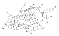
図1は、この発明を実施するための実施の形態1における板材の突合せレーザ溶接方法を用いるレーザ溶接装置の構成図である。この装置は、被溶接板材である先行板材6aと後行板材6bを保持固定するクランプ装置1a、1bを備えている。また、このクランプ装置1a、1bには、板材を保持したクランプ装置を動かして板材の対向する端部にある被溶接部の間隔を調整する調整手段を備えている。また、板材をレーザで加工する加工ヘッド2と、その加工ヘッド2にレーザビームを供給するレーザ光発振器3と、突合せ溶接前に被溶接板材にせん断加工を施すシャー切断機4と、加工ヘッド2とシャー切断機4を搭載し被溶接部に沿って板幅方向に移動するキャリッジ(搬送手段)5と、板材6を送り出すワーク供給装置7とを備えている。なお、ここでは図示していないが、これらを制御するNC(Numerical Control)制御装置があっても良い。
Embodiment 1 FIG.
FIG. 1 is a configuration diagram of a laser welding apparatus using a plate material butt laser welding method according to Embodiment 1 for carrying out the present invention. This apparatus includes
次に、この溶接装置を用いた溶接法方法について説明する。図2に示すように、先行板材6aとワーク供給装置7により送り出された後行板材6bとをクランプ装置1a、1bで固定する。シャー切断機4は、上下移動可能な上刃8と、板材6を支える下刃9とから構成されており、上刃8を降下させることで板材6を切断する。この時、対象となる板厚により、上刃8を左右に移動させることで、クリアランス10を調整できるようになっている。
Next, a welding method using this welding apparatus will be described. As shown in FIG. 2, the preceding
その後、シャー切断機4により切断された板材6を保持しながら、クランプ1a、1bの間隔を調整する。通常の突合せ溶接を行う場合ならば、図3に示す板材6a、6bの両端部6aE、6bEを突合せる。しかし、図4に示すように、シャー切断された板材6の切断精度が悪い場合、板材6を突合せた際に、ある一部分は突き当たるが、ある一部分ではギャップGが空いた状態となり、このまま溶接を行うと溶接不良を起こすこととなる。
Thereafter, the distance between the
この発明では、先ず、図3のようにギャップGをある程度空けた状態で、板材間の間隔をクランプ1a、1bの調整手段で調整する。この時のギャップ調整は、板材の被溶接部のギャップを測定して、いずれの場所においても後述する溶接許容ギャップを越えた状態となるように調整しても良いし、ある程度大雑把に広めの間隔を設定しても良い。つまり、レーザ照射の際いずれの場所においても溶接されなければよいのである。その後、被溶接板材の溶接開始点の真上に加工ヘッド2がくるように、キャリッジ5を走行させる。なお、板材6の直下には、11aを軸にして回転が可能な円柱状のバックロール11bがあり、これは、加工ヘッド2が搭載されているキャリッジ5の下部に取り付けられている。
In the present invention, first, the gap between the plate members is adjusted by the adjusting means of the
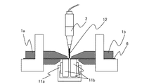
その後、図5に示すように、レーザ12を照射させながらキャリッジ5を走行させ、被溶接部である板材端部を一時的に溶解させる。この時、板材表面に照射されているレーザ12のスポット径は、ギャップGより大きい方が良い。そのため、加工ヘッド2を上下させることで、ビームの焦点位置を変化させ、スポット径の大きさが変更できることが望ましい。また、スポット径が小さく、板材の両端面を1回で溶解させることができない場合でも、キャリッジを往復させることで、端面を1回ずつ、一時的に溶解させることも可能である。レーザビーム照射中はシールドガス、ここではアルゴンガスを、加工ヘッド2等に取り付けられたノズル先端から吹付けることで、溶融金属の酸化を防止すると良い。
Thereafter, as shown in FIG. 5, the
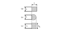
図6にはレーザビームを照射した後の板材の状態を示す。板材6の両端面が一部溶解し球状の形状となる。この時、板材6の端面が球状となると、ギャップGはレーザビーム照射前よりも大きくなる。次にクランプ1a、1bを移動させギャップGを調整し、板材6を突合せる。その後、突合せ部に沿ってレーザビームを照射することで溶接不良のない、良好な溶接が可能となる。この突合せ状態において、ギャップが必ずしもゼロとなる必要は無く、多少ギャップが空いている状態でも、板材6の両端面が部分的に板厚の増加した形状となるため、ギャップ裕度が広くなり、溶接が可能となる。すなわち、板材間の間隔を狭めた後の被溶接部の間隔が、いずれの場所でも後述する溶接可能な許容ギャップ内であればよい。
FIG. 6 shows the state of the plate after the laser beam irradiation. A part of both end surfaces of the
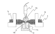
図7は板材の端面を球状に加工した後の突合せ溶接時の状態を示した図である。球状化処理を行った板材を突合せ、例えばレーザ出力:2.0kW、溶接速度:13m/min、ビームスポット径:0.6mmで溶接を行う。その際、溶接中に溶融金属に酸素が溶解すると表面張力が低下し、溶融金属の自重と表面張力とのつりあいのバランスが崩れ、溶融ビードが不安定になる。その結果、溶接部のビードの垂れ下がりや溶け落ちが生じる。これを防ぐために、加工ヘッド2の先端にあるノズルからシールドガス(アルゴンガス)13aを溶接部に吹きつけ、溶融金属の酸化を抑制するとよい。さらに、溶接時に板材の裏からノズル14により、シールドガス(アルゴンガス)13bを当てるバックシールドを行うことで、加工ヘッド2の先端にあるノズルのみからのシールドよりも強力となり、安定した溶接が可能となる。また、シールドガスとして、アルゴンの代わりに熱伝導率の高いヘリウムを使用しても良い。
FIG. 7 is a view showing a state at the time of butt welding after the end surface of the plate material is processed into a spherical shape. The spheroidized plate materials are butted together and, for example, welding is performed at a laser output of 2.0 kW, a welding speed of 13 m / min, and a beam spot diameter of 0.6 mm. At that time, if oxygen is dissolved in the molten metal during welding, the surface tension is lowered, the balance between the weight of the molten metal and the surface tension is lost, and the molten bead becomes unstable. As a result, the bead hangs down or melts down at the weld. In order to prevent this, a shield gas (argon gas) 13a may be blown from the nozzle at the tip of the
なお、溶接中のレーザビームが照射されている板材6の直下にバックロール11bが無い場合、クランプ状態にある板材6の板厚が薄い程、剛性が小さくなり、板材が垂れてしまい、突合せ溶接が不可能となる。このバックロール11bはレーザビームが照射されている部分の板材を下から持ち上げ、クランプと挟み、固定することで、板材の両端面の目違いを防ぐ役目がある。バックロール11bはキャリッジ5に取り付けられているため、キャリッジ5の走行に沿って、随時、レーザビーム照射部の直下に位置し、溶接を安定にすることができる。なお、一度目のレーザビーム照射と二度目のレーザビーム照射による溶接の際に、バックロール11bが板材の両端面の球状となる部分に当たらないようにする必要がある。
In addition, when there is no
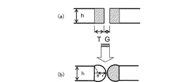
以下に板材の突合せ溶接における最大許容ギャップについて、簡単なモデルを用いた理論値と実験値の比較を行い詳細に説明する。使用したモデルを図8に示す。これは、板厚hの突合せ溶接においてGのギャップがある状態で板材の端面からTだけ溶かした時、端面に半径rの半球状の溶融金属が生じるモデルである。ある板厚hと溶け代Tの値を決定することで半径rとθ(=π−濡れ角)が一義的に決まるので、図8(b)の溶融金属がブリッジを形成する(両方の半球状の溶融金属が接する)と仮定すると、Gが求められる。次に、溶け代Tを変化させていき最大許容ギャップGmaxを求める。以下に計算手法を示す。まず、図8より以下の3つの関係式が導かれる。 In the following, the maximum allowable gap in butt welding of plate materials will be described in detail by comparing theoretical values and experimental values using a simple model. The model used is shown in FIG. This is a model in which a hemispherical molten metal having a radius r is formed on the end face when only T is melted from the end face of the sheet material in a state where there is a gap of G in butt welding with a thickness h. Since the radius r and θ (= π−wetting angle) are uniquely determined by determining the value of a certain plate thickness h and the melting allowance T, the molten metal in FIG. 8B forms a bridge (both hemispheres). Assuming that the molten metal is in contact, G is obtained. Next, the maximum allowable gap Gmax is obtained by changing the melting allowance T. The calculation method is shown below. First, the following three relational expressions are derived from FIG.

上記の連立方程式からギャップGを半径rとθで表すため、先ず(2)式より(4)式が導かれ、これに(1)式を代入すると(5)式となる。さらに(3)式に(5)式を代入すると(6)式が得られる。 In order to express the gap G by the radii r and θ from the above simultaneous equations, first, the equation (4) is derived from the equation (2), and the equation (5) is obtained by substituting the equation (1). Further, when equation (5) is substituted into equation (3), equation (6) is obtained.
このように許容ギャップGが半径rとθで表せる。次に、板厚0.1mmとして溶け代を0.01mmから0.10mmまで変化させた時の許容ギャップを図9に示す。溶け代が0.04mmの時に許容ギャップが0.021mmと最大になる。さらに、ビームスポット径を0.6mmとし、板厚を0.4mm、1.6mmの時の最大許容ギャップGmaxを求め、実験値と比較した結果を図10に示す。この図より、板厚が増加するとギャップが広くなっても溶接が可能となることがわかる。 Thus, the allowable gap G can be expressed by the radii r and θ. Next, FIG. 9 shows the allowable gap when the melting thickness is changed from 0.01 mm to 0.10 mm with a plate thickness of 0.1 mm. When the melting allowance is 0.04 mm, the allowable gap is maximum at 0.021 mm. Further, the maximum allowable gap Gmax when the beam spot diameter is 0.6 mm, the plate thickness is 0.4 mm, and 1.6 mm is obtained, and the result compared with the experimental value is shown in FIG. From this figure, it can be seen that as the plate thickness increases, welding is possible even if the gap becomes wider.
さて、この結果より、図11(a)に示すように、例えば板厚hが0.5mmの場合、突合せ状態でギャップが100μmまで空いていたとしても、不良なく溶接が可能である。しかし、本発明の方法により、例えば、レーザ出力:1.5kW、溶接速度:12m/min、ビームスポット径:1mmで板材の端面から溶け代Tを860μmとすることで、図11(b)のような端面に半径390μmの半球状化した板材が得られる。これは、端部が膨らんで板厚が増加したと見なす事ができるので、ここで、図11(c)のように半球状の断面積と同等の四角状の端面を考えると、板厚hAは0.62mmの端部と考えることができ、もう片方の板材にも同様の処理を施すことで、板材間のギャップ裕度の拡大が期待でき、突合せ状態でギャップが130μmまで許容できることになる。 From this result, as shown in FIG. 11A, for example, when the plate thickness h is 0.5 mm, even if the gap is 100 μm in the butt state, welding can be performed without defect. However, according to the method of the present invention, for example, the laser output is 1.5 kW, the welding speed is 12 m / min, the beam spot diameter is 1 mm, and the melting allowance T is set to 860 μm from the end face of the plate material. A hemispherical plate material having a radius of 390 μm is obtained on the end face. This can be regarded as an increase in the plate thickness due to the bulge of the end portion. Here, considering a square end surface equivalent to a hemispherical cross-sectional area as shown in FIG. A can be considered as an end of 0.62 mm, and by applying the same treatment to the other plate material, it is possible to expect an increase in the gap tolerance between the plate materials, and to allow a gap of up to 130 μm in the butt state. Become.
なお、ここでは最初のレーザ照射による端面の球状化の際、先行板材と後行板材の両方の端部にレーザを照射しているが、最初のギャップ量が小さい時は、一方の板材だけにレーザ照射をしてもよい。 In this case, when spheroidizing the end surface by the first laser irradiation, the laser is irradiated to the end portions of both the preceding plate material and the following plate material, but when the initial gap amount is small, only one plate material is irradiated. Laser irradiation may be performed.
このように構成されたレーザ溶接方法及びレーザ溶接装置によれば、溶接に先立って被溶接部にレーザビームを照射して一時的に溶解させ、その後突合せ溶接を行うので、切削加工装置や研削加工工程が必要無くなり、コスト低減と溶接工程の時間短縮が可能となる。更に、端面の球状化により端部の板厚が増加したと見なせるので、板材間のギャップ裕度の拡大が期待でき、突合せ精度が多少悪くても溶接可能となる。 According to the laser welding method and the laser welding apparatus configured as described above, the welding portion is irradiated with a laser beam prior to welding to be temporarily melted, and then butt welding is performed. This eliminates the need for a process, thereby reducing costs and shortening the welding process time. Furthermore, since it can be considered that the thickness of the end portion has increased due to the spheroidization of the end surface, an increase in the gap tolerance between the plate materials can be expected, and welding is possible even if the butt accuracy is somewhat poor.
また、板材の両端面を球状にする際や溶接の際に、加工ヘッドや板材の裏面からシールドガスを吹き付け、レーザビームを照射するようにすれば、溶融金属の酸化を防止する事ができる。その結果、溶解した金属の表面張力の低下を防いで自重による垂れ下がりを防止し、球状を保つことができるので、端部の板厚増加による溶接の裕度の拡大が期待でき、突合せ精度が多少悪くても溶接可能となる。その際、シールドガスとしてヘリウムガスを用いると、溶接ビードの冷却を促し、溶融金属の自重の増加やその変形を抑制することができるので、より安定した溶接が可能となる。 Further, when the both end surfaces of the plate material are made spherical or welded, if a shield gas is blown from the back surface of the processing head or the plate material to irradiate the laser beam, oxidation of the molten metal can be prevented. As a result, the surface tension of the melted metal can be prevented from being lowered, it can be prevented from sagging due to its own weight, and the spherical shape can be maintained. Even if it is bad, welding is possible. At this time, when helium gas is used as the shielding gas, cooling of the weld bead is promoted, and increase in the weight of the molten metal and deformation thereof can be suppressed, so that more stable welding is possible.
さらに、バックロールを備えていれば、薄板材の垂れ下がりを防止でき、薄板材の両端面の目違いを防ぐ事が可能である。また、バックロールはキャリッジに取り付けられているため、キャリッジの走行に沿って、随時、レーザビーム照射部の直下に位置するので、溶接を安定にすることができるという効果も併せ持つ。 Furthermore, if the back roll is provided, it is possible to prevent the thin plate material from drooping, and to prevent a mistake in the both end faces of the thin plate material. In addition, since the back roll is attached to the carriage, it is located at any time directly below the laser beam irradiation section along the carriage travel, so that the welding can be stabilized.
実施の形態2.
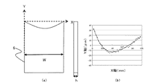
ここでは、実際の薄板材を用い、突合せ溶接を行う前に板材端部にレーザを照射させた際の板材の形状変化について説明する。板材の鋼板としては、普通鋼、高張力鋼、高炭素鋼、電磁鋼板、ステンレス鋼などがある。一例として図12に溶接に使用する薄板材の形状を示す。板厚hが0.1mm、板幅Wが100mmであり、シャー切断による板端面の凹凸量は約50μmである。つまり、シャー切断後の板材をそのまま突合わせた場合、板中央部に約100μmものギャップが空くことになる。図9に示したように板厚0.1mmの突合せ溶接において、溶接可能な許容ギャップは21μmであり、シャー切断板材では溶接不可能となる。
Here, a description will be given of a change in shape of the plate material when an actual thin plate material is used and laser is applied to the end of the plate material before performing butt welding. Examples of plate steel include plain steel, high-tensile steel, high-carbon steel, electromagnetic steel plate, and stainless steel. As an example, FIG. 12 shows the shape of a thin plate material used for welding. The plate thickness h is 0.1 mm, the plate width W is 100 mm, and the unevenness of the plate end surface by shear cutting is about 50 μm. In other words, when the plate materials after cutting the shear are abutted together, a gap of about 100 μm is left at the center of the plate. As shown in FIG. 9, in butt welding with a plate thickness of 0.1 mm, the allowable gap that can be welded is 21 μm, and it is impossible to weld with a shear-cut plate material.
次に、図13(a)にシャー切断後の板材に端面の球状化を行うためのレーザビーム照射状態を示す。この時の溶接条件は例えば、レーザ出力:300W、溶接速度:5m/min、ビームスポット径R:0.6mm、ビーム照射位置L:0.1mmである。板材端面の球状化処理は、板材をどの程度、溶解させるかにより球状化する大きさが異なり、特に、ビーム照射位置L(溶け代Tと関連)は大きく影響する。今回、図12に示した板材では、板端面の凹凸量が板幅方向(溶接方向)のX=0mm付近で32μm、X=100mm付近で16μmと、16μmの差がある。このような場合、一度のレーザ照射で球状化処理を行う方法以外にも、途中でビーム照射位置Lを変化させる方法もある。また、X=0mmからX軸プラス方向、X=100mmからX軸マイナス方向と2回に分けてレーザ照射を行うと、より凹凸が減少することも考えられる。なお、この際は、X軸プラス方向へのビーム照射は板材が最も凹んでいるX=40mm付近までで、その後はレーザをオフにして、キャリッジを走行させ、ビーム照射位置Lを変化後、X軸マイナス方向へのビーム照射はレーザが照射されていない部分X=100mmからX=40mmの間として球状化処理を行えばよい。 Next, FIG. 13A shows a laser beam irradiation state for spheroidizing the end face of the plate material after shear cutting. The welding conditions at this time are, for example, laser output: 300 W, welding speed: 5 m / min, beam spot diameter R: 0.6 mm, and beam irradiation position L: 0.1 mm. The spheroidizing treatment of the plate material end face differs in the size of spheroidization depending on how much the plate material is melted. In particular, the beam irradiation position L (related to the melting allowance T) has a great influence. In this case, in the plate material shown in FIG. 12, there is a difference of 16 μm between the concavo-convex amount of the plate end surface at 32 μm near X = 0 mm in the plate width direction (welding direction) and 16 μm near X = 100 mm. In such a case, there is a method of changing the beam irradiation position L in the middle other than the method of performing the spheroidizing process by a single laser irradiation. Further, it is conceivable that the unevenness is further reduced when the laser irradiation is performed twice from X = 0 mm to the X-axis plus direction and X = 100 mm to the X-axis minus direction. At this time, the beam irradiation in the X-axis plus direction is up to the vicinity of X = 40 mm where the plate material is most concave, and thereafter the laser is turned off, the carriage is run, and the beam irradiation position L is changed. The beam irradiation in the negative direction of the axis may be performed as a spheroidizing process by setting a portion where the laser is not irradiated between X = 100 mm and X = 40 mm.
図13(b)には、X軸プラス方向へおよそX=60mmまでのレーザ照射を行った結果を示す。この結果から凸部の最大は+4.0μm、凹部の最大は−5.7μmであり、凹凸量は9.7μmとなった。このように、レーザ照射前の凹凸量の50μmと比べ、凹凸が減少するという効果が見られる。なお、同様の処理を繰返す、つまり、複数回レーザを照射することも可能である。 FIG. 13B shows the result of laser irradiation up to approximately X = 60 mm in the positive direction of the X axis. From this result, the maximum convex portion was +4.0 μm, the maximum concave portion was −5.7 μm, and the unevenness amount was 9.7 μm. Thus, the effect that the unevenness is reduced is seen compared with the unevenness amount of 50 μm before the laser irradiation. It is also possible to repeat the same process, that is, to irradiate the laser a plurality of times.
このように、板材を突合せた時の当初のギャップG(図14(a)参照)は約100μmあったが、斜線部へのレーザ照射(照射位置は適宜変更してもよい)により、図14(b)のように板材間のギャップGは9.7×2=19.4μmとなり、板厚0.1mmの突合せ許容ギャップ内であるため、その後の突合せ溶接は可能となる。 As described above, the initial gap G (see FIG. 14A) when the plate members were butted was about 100 μm. However, the laser irradiation (irradiation position may be changed as appropriate) to the hatched portion, FIG. As shown in (b), the gap G between the plate members is 9.7 × 2 = 19.4 μm, which is within the butt allowable gap with a plate thickness of 0.1 mm, so that subsequent butt welding is possible.
なお、ギャップが減少するのは、突合せ溶接を行う前にレーザを被溶接板材の両端面に照射することで端面が一部溶解し、表面張力の影響により球状の形状をした被溶接板材が得られるためであり、その際、板材の角部は中央部よりも溶解量が大きく、相対的に球状半径が大きくなり後退量が増える(Y軸の値が小さくなる)ためと考えられる。なお、その後の突合せ溶接後のビート形状を見て中央部と角部の溶接部の肉厚を比較すると本方法の使用が分かる場合がある。 Note that the gap is reduced by irradiating laser on both end faces of the plate to be welded before performing butt welding, so that a part of the end surface is melted to obtain a plate to be welded having a spherical shape due to the influence of surface tension. In this case, it is considered that the corner portion of the plate material has a larger amount of dissolution than the center portion, and the spherical radius becomes relatively larger and the retraction amount increases (the Y-axis value becomes smaller). Note that the use of this method may be found by comparing the thickness of the central and corner welds by looking at the beat shape after the subsequent butt welding.
このように、レーザ溶接前の板材端部へのレーザ照射には、ギャップ裕度の向上と共に凹凸量の減少という効果もあるため、溶接が容易となり、研削装置や研削工程が不要になるため、コストが低減でき、溶接工程の時間短縮が可能となる。 Thus, the laser irradiation to the end of the plate material before laser welding has the effect of improving the gap tolerance and reducing the amount of unevenness, so that welding becomes easy, and a grinding device and a grinding process become unnecessary. Cost can be reduced and the welding process time can be shortened.
実施の形態3.
ここでは実施の形態1、2のレーザ溶接方法を用いるレーザ溶接装置例について述べる。図15は撮像装置16を加工ヘッド2に取り付けた状態を示した図である。ハーフミラー15と撮像装置16をレーザ光と同軸にセットすることで、溶接前の板材の突合せ状態を確認したり、突合せ部のレーザ照射位置を容易に合わせたりすることができる。また、画像処理装置17とNC制御装置19も備えている。
Here, an example of a laser welding apparatus using the laser welding method of the first and second embodiments will be described. FIG. 15 is a diagram illustrating a state in which the
レーザ照射による端面の球状化後、突合せ溶接をするためには、クランプ装置1a、1bを接近させて、溶接可能な突合せ位置までギャップGを調整する必要があるが、薄板材の場合は、目違いを生じさせずにギャップGを狭めて突合せることは困難である。そのため、キャリッジ5を再度、溶接線方向に移動させながら、図15のように、加工ヘッド2に取り付けられている撮像装置16の映像を画像処理装置17を用いて、両板材間の最も狭いギャップ量を計測し、その後、NC制御装置19の指示によりこの最小ギャップ量だけクランプを移動させれば、目違いを生じさせずに突合わせることができる。
In order to perform butt welding after spheroidizing the end face by laser irradiation, it is necessary to bring the
このように構成されたレーザ溶接装置のNC制御装置19動作指示について図16を用いて説明する。この図は、撮像装置16を用いたレーザ突合せ溶接の動作手順の概要を示したフローチャートである。ステップ111のスタートに引き続き、ステップ112で先行板材6aの終端部分をクランプし、後行板材6bをワーク供給装置により、レーザ溶接加工機へ供給する。ステップ113で後行板材6bをクランプし、ステップ114でクランプされた板材をシャー切断機4にて切断する。ステップ115では、溶接許容ギャップを越えるようにギャップ調整を行い、加工ヘッド2に取り付けられた撮像装置16により、レーザ照射の位置決めを行う。ステップ116で、レーザを照射し、板材の端面の球状化加工を行う。その後、キャリッジ5を移動させて撮像装置16の映像を画像処理装置17によって画像処理し、突合せギャップを計測する(ステップ117)。その際の最小ギャップ分だけクランプを移動させてギャップ調整を行い(ステップ118)、ステップ119でレーザを照射し溶接を行い、ステップ120で溶接工程が終了する。
The operation instruction of the
なお、ここでは、測定された最小ギャップ分だけクランプを移動させているが、これにより最小ギャップの所の板材が突き当てられて接触している。そのため、それ以上移動させると目違いが生じることになる。良好な溶接が可能となるには、板材間の間隔を狭めた後の被溶接部の間隔が、いずれの場所でも溶接可能な許容ギャップ内であればよいため、必ずしも測定された最小ギャップ分だけクランプを移動させる必要は無く、最小ギャップ分よりも若干移動量を小さくしても良い。 Here, although the clamp is moved by the measured minimum gap, the plate material at the position of the minimum gap is abutted and brought into contact therewith. Therefore, if it is moved further, a mistake will occur. In order to achieve good welding, it is sufficient that the interval between the welded parts after the interval between the plate members is within the allowable gap that can be welded at any location. There is no need to move, and the amount of movement may be slightly smaller than the minimum gap.
このように構成されたレーザ溶接装置によれば、NC制御装置の指示により溶接に先立って被溶接部にレーザビームを照射して一時的に溶解させ、その後ギャップを調整して突合せ溶接を行うので、切削加工装置や研削加工工程が必要無くなり、コスト低減と溶接工程の時間短縮が可能となる。また、溶接位置とギャップを正確に測定できるので、目違いを生じさせることなく突合せる事ができ、安定な溶接を行う事ができる。 According to the laser welding apparatus configured as described above, the welded portion is irradiated with a laser beam prior to welding according to an instruction from the NC control apparatus to be temporarily melted, and then the gap is adjusted to perform butt welding. This eliminates the need for a cutting device and a grinding process, thereby reducing costs and shortening the welding process time. Further, since the welding position and the gap can be accurately measured, the welding can be performed without causing a mistake, and stable welding can be performed.
実施の形態4.
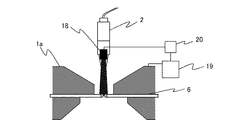
ここでは実施の形態1、2のレーザ溶接方法を用いた他のレーザ溶接装置例について述べる。実施の形態3の溶接装置は、撮像装置16を用いていたが、ここでは2次元レーザ変位センサを用いる場合について述べる。図17は2次元レーザ変位センサ18を加工ヘッド2のレーザ照射方向の後ろ側に取り付けた状態を示した図である。また、検査装置20とNC制御装置19も備えている。
Here, another example of the laser welding apparatus using the laser welding method of the first and second embodiments will be described. Although the
レーザビームによって両板材の端部を球状に加工する際、2次元レーザ変位センサ18は、加工ヘッド2のレーザ照射方向の後ろ側に取り付けられているため、板材の端面球状化加工の直後に、ギャップGが測定できる。この2次元レーザ変位センサ18からの最小ギャップ量を検査装置20で読み取り、NC制御装置19の指示により最小ギャップ量分だけクランプを移動させればよい。
Since the two-dimensional
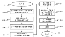
このように構成されたレーザ溶接装置のNC制御装置19動作指示について図18を用いて説明する。この図は、2次元レーザ変位センサ18を用いたレーザ突合せ溶接の動作手順の概要を示したフローチャートである。ステップ211のスタートに引き続き、ステップ212で先行板材6aの終端部分をクランプし、後行板材6bをワーク供給装置により、レーザ溶接加工機へ供給する。ステップ213で後行板材6bをクランプし、ステップ214でクランプされた板材をシャー切断機4にて切断する。ステップ215では、溶接許容ギャップを越えるようにギャップ調整を行い、加工ヘッド2に取り付けられたCCDカメラあるいは、2次元レーザ変位センサ18と検査装置20により、レーザ照射の位置決めを行う。ステップ216で、レーザを照射し、板材の端面の球状化加工を行う。その際、加工ヘッド2のレーザ照射方向の後ろ側に取り付けられた、2次元レーザ変位センサ18にて、突合せギャップを計測する(ステップ217)。その際の最小ギャップ相当分だけクランプを移動させ(ステップ218)、ステップ219でレーザを照射し溶接を行い、ステップ220で溶接工程が終了する。
An operation instruction of the
なお、ここでは、2次元レーザ変位センサ18は、加工ヘッド2に取り付けられているが、レーザ照射方向の後ろ側にあればよいので、キャリッジ5に直接取り付けられていても良い。
Here, the two-dimensional
このように構成されたレーザ溶接装置によれば、端面の球状化と同時にギャップを測定するので、時間短縮ができる。また、ギャップを正確に測定できるので、目違いを生じさせることなく突合せる事ができ、安定な溶接を行う事ができる。 According to the laser welding apparatus configured in this way, the gap is measured simultaneously with the spheroidization of the end face, so that the time can be shortened. In addition, since the gap can be measured accurately, it is possible to make a match without causing a mistake and stable welding can be performed.
1a クランプ装置、1b クランプ装置、2 加工ヘッド、3 レーザ光発振器、4 シャー切断機、5 キャリッジ、6 板材、6a 先行板材、6b 後行板材、6aE 端部、6bE 端部、7 ワーク供給装置、8 上刃、9 下刃、10 クリアランス、11a バックロール軸、11b バックロール、12 レーザ、13a シールドガス、13b シールドガス、14 ノズル、15 ハーフミラー、16 撮像装置、17 画像処理装置、18 2次元レーザ変位センサ、19 NC制御装置、20 検査装置、G ギャップ、Gmax 最大許容ギャップ、h 板厚、ha 板厚、L 板材端面からのレーザビーム照射位置、R レーザビームのスポット径、T 溶け代、W 板幅、X X軸、Y Y軸、r レーザビーム照射後の板端面に生じる半球状の半径、θ π―濡れ角。 1a clamping device, 1b clamping device, 2 machining head, 3 laser light oscillator, 4 shear cutting machine, 5 carriage, 6 plate material, 6a preceding plate material, 6b following plate material, 6a E end, 6b E end, 7 work supply Device, 8 Upper blade, 9 Lower blade, 10 Clearance, 11a Back roll shaft, 11b Back roll, 12 Laser, 13a Shield gas, 13b Shield gas, 14 Nozzle, 15 Half mirror, 16 Imaging device, 17 Image processing device, 18 Two-dimensional laser displacement sensor, 19 NC control device, 20 inspection device, G gap, Gmax maximum allowable gap, h plate thickness, ha plate thickness, L laser beam irradiation position from end face of plate material, spot diameter of R laser beam, T melting , W plate width, XX axis, Y Y axis, r hemispherical radius generated on the plate end face after laser beam irradiation, θ π-wetting Horn.
Claims (4)
前記一対の板材の被溶接部の間隔が溶接許容ギャップ内となるように調整するギャップ調整工程と、
前記被溶接部にレーザを照射して前記板材の溶接を行う第二の照射工程と
を備えたレーザ溶接方法。 A laser beam is irradiated from the end face of the plate material of at least one of the pair of plate members facing each other, and the laser beam is irradiated to the welded portion a plurality of times to temporarily melt the welded portion. Irradiation process,
A gap adjusting step for adjusting the distance between the welded portions of the pair of plate members to be within the welding allowable gap;
A laser welding method comprising: a second irradiation step of welding the plate member by irradiating the welded portion with a laser.
前記一対の板材の溶接前に被溶接部の間隔を調整するギャップ調整手段と、を備えたレーザ溶接装置。 After the irradiation position is changed from the end face of the plate material of at least one of the pair of plate materials held facing the welding portion, laser irradiation is performed a plurality of times, and the welding portion is temporarily melted. A processing head for welding the plate material by irradiating the welded portion of the plate material with a laser;
And a gap adjusting means for adjusting an interval between the welded parts before welding the pair of plate members.
Priority Applications (1)
| Application Number | Priority Date | Filing Date | Title |
|---|---|---|---|
| JP2012032998A JP2012115909A (en) | 2012-02-17 | 2012-02-17 | Laser welding method and laser welding apparatus |
Applications Claiming Priority (1)
| Application Number | Priority Date | Filing Date | Title |
|---|---|---|---|
| JP2012032998A JP2012115909A (en) | 2012-02-17 | 2012-02-17 | Laser welding method and laser welding apparatus |
Related Parent Applications (1)
| Application Number | Title | Priority Date | Filing Date |
|---|---|---|---|
| JP2008049560A Division JP2009202222A (en) | 2008-02-29 | 2008-02-29 | Laser beam welding method and laser beam welding apparatus |
Publications (1)
| Publication Number | Publication Date |
|---|---|
| JP2012115909A true JP2012115909A (en) | 2012-06-21 |
Family
ID=46499390
Family Applications (1)
| Application Number | Title | Priority Date | Filing Date |
|---|---|---|---|
| JP2012032998A Pending JP2012115909A (en) | 2012-02-17 | 2012-02-17 | Laser welding method and laser welding apparatus |
Country Status (1)
| Country | Link |
|---|---|
| JP (1) | JP2012115909A (en) |
Citations (4)
| Publication number | Priority date | Publication date | Assignee | Title |
|---|---|---|---|---|
| JPH01317694A (en) * | 1988-06-15 | 1989-12-22 | Mitsubishi Electric Corp | Method for laser butt welding of sheets |
| JPH0760466A (en) * | 1993-08-25 | 1995-03-07 | Amada Co Ltd | Laser beam welding method |
| JP2002331383A (en) * | 2001-05-08 | 2002-11-19 | Koike Sanso Kogyo Co Ltd | Monitoring device for cutting |
| JP2005014027A (en) * | 2003-06-24 | 2005-01-20 | Enshu Ltd | Weld zone image processing method, welding management system, feedback system for welding machine, and butt line detection system |
-
2012
- 2012-02-17 JP JP2012032998A patent/JP2012115909A/en active Pending
Patent Citations (4)
| Publication number | Priority date | Publication date | Assignee | Title |
|---|---|---|---|---|
| JPH01317694A (en) * | 1988-06-15 | 1989-12-22 | Mitsubishi Electric Corp | Method for laser butt welding of sheets |
| JPH0760466A (en) * | 1993-08-25 | 1995-03-07 | Amada Co Ltd | Laser beam welding method |
| JP2002331383A (en) * | 2001-05-08 | 2002-11-19 | Koike Sanso Kogyo Co Ltd | Monitoring device for cutting |
| JP2005014027A (en) * | 2003-06-24 | 2005-01-20 | Enshu Ltd | Weld zone image processing method, welding management system, feedback system for welding machine, and butt line detection system |
Similar Documents
| Publication | Publication Date | Title |
|---|---|---|
| JP6799755B2 (en) | Laser welding method | |
| TWI483801B (en) | Laser beam welding method and laser beam welding apparatus for steel sheet | |
| US10857624B2 (en) | Laser-beam welding method and laser-beam welding apparatus | |
| CN109843498B (en) | Method and system for welding using an energy beam that is repetitively scanned in two dimensions | |
| US20120024828A1 (en) | Method of hybrid welding and hybrid welding apparatus | |
| CN109562491B (en) | Aluminum alloy laser welding system and method for laser welding aluminum alloy | |
| JP6327172B2 (en) | Laser welding system and laser welding method | |
| EP3090830B1 (en) | Laser welding method | |
| JP2009202222A (en) | Laser beam welding method and laser beam welding apparatus | |
| JP2018051607A (en) | Laser weld device | |
| US11801573B2 (en) | Tack welding method and tack welding apparatus | |
| JP2012115909A (en) | Laser welding method and laser welding apparatus | |
| US20230001513A1 (en) | Method for laser welding two coated workpieces | |
| JP6495987B2 (en) | Butt laser welding method and laser welding member | |
| CN110997219A (en) | Hybrid welding method and hybrid welding device | |
| JP2014024078A (en) | Laser welding apparatus | |
| JP5692293B2 (en) | Laser welding method and laser welding apparatus for metal plate | |
| JP6211340B2 (en) | Welding apparatus and welding method | |
| JP2010214402A (en) | Laser welding method and laser welding apparatus for metal plate | |
| JP2010064086A (en) | Composite welding method and composite welding apparatus | |
| JP7435834B2 (en) | Laser beam welding method, welding machine, and manufacturing method for butt welding joints | |
| JP7294565B1 (en) | Butt laser beam welding method | |
| JP2008126297A (en) | Laser beam welding method and its apparatus | |
| JP2020044543A (en) | Lazer welding method |
Legal Events
| Date | Code | Title | Description |
|---|---|---|---|
| A02 | Decision of refusal |
Free format text: JAPANESE INTERMEDIATE CODE: A02 Effective date: 20131015 |