JP2012114476A - Optical fiber for amplification - Google Patents
Optical fiber for amplification Download PDFInfo
- Publication number
- JP2012114476A JP2012114476A JP2012060646A JP2012060646A JP2012114476A JP 2012114476 A JP2012114476 A JP 2012114476A JP 2012060646 A JP2012060646 A JP 2012060646A JP 2012060646 A JP2012060646 A JP 2012060646A JP 2012114476 A JP2012114476 A JP 2012114476A
- Authority
- JP
- Japan
- Prior art keywords
- region
- refractive index
- optical fiber
- band
- amplification optical
- Prior art date
- Legal status (The legal status is an assumption and is not a legal conclusion. Google has not performed a legal analysis and makes no representation as to the accuracy of the status listed.)
- Pending
Links
Images


Abstract
Description
本発明は、増幅用光ファイバに関するものである。 The present invention relates to an optical fiber for amplification.
信号光を伝送することにより大量の情報を高速に送受信することができる光通信システムにおいて、一般に信号光伝送線路として石英系光ファイバが用いられる。また、信号光波長帯域としては、石英系光ファイバの伝送損失が小さいCバンド(1530nm〜1565nm)やLバンド(1565nm〜1625nm)が用いられ、さらにSバンド(1460nm〜1530nm)も用いられる。 In an optical communication system capable of transmitting and receiving a large amount of information at high speed by transmitting signal light, generally, a silica-based optical fiber is used as a signal light transmission line. Further, as the signal light wavelength band, a C band (1530 nm to 1565 nm) or L band (1565 nm to 1625 nm) with a small transmission loss of the silica-based optical fiber is used, and an S band (1460 nm to 1530 nm) is also used.
また、光通信システムでは、信号光伝送線路により伝送される間に信号光が損失を被ることから、信号光を光増幅する光増幅器が光送信器,光中継器および光受信器などに設けられる。光増幅器としては一般に光ファイバ増幅器が用いられる。光ファイバ増幅器は、希土類元素や遷移金属元素等の光学活性元素がコア領域に添加された増幅用光ファイバを光増幅媒体として備え、この光学活性元素を励起し得る波長の励起光を増幅用光ファイバに供給することで、この増幅用光ファイバにおいて信号光(被増幅光)を光増幅する。 In an optical communication system, since signal light suffers loss while being transmitted through a signal light transmission line, an optical amplifier that optically amplifies the signal light is provided in an optical transmitter, an optical repeater, an optical receiver, and the like. . In general, an optical fiber amplifier is used as the optical amplifier. An optical fiber amplifier includes an amplification optical fiber in which an optically active element such as a rare earth element or a transition metal element is added to a core region as an optical amplification medium, and amplifying light having a wavelength capable of exciting the optically active element. By supplying to the fiber, the signal light (amplified light) is optically amplified in the amplification optical fiber.
このような光ファイバ増幅器において、高利得で信号光を光増幅することが重要であるとともに、信号光に対してノイズとなる自然放出光(ASE光)の発生を抑制することも重要である。しかし、高利得を得ようとするには、増幅用光ファイバに添加されている光学活性元素の反転分布率を高くする必要があり、そうするとASE光の発生量が多くなってしまう。すなわち、従来の増幅用光ファイバでは高利得とASE光抑制とは両立し得ない。 In such an optical fiber amplifier, it is important to optically amplify the signal light with high gain, and it is also important to suppress the generation of spontaneous emission light (ASE light) that becomes noise with respect to the signal light. However, in order to obtain a high gain, it is necessary to increase the inversion distribution ratio of the optically active element added to the amplification optical fiber, which increases the amount of ASE light generated. That is, the conventional gain optical fiber cannot achieve both high gain and ASE light suppression.
例えば、希土類元素であるEr元素が添加された増幅用光ファイバ(EDF:Erbium-doped fiber)を光増幅媒体として備える光ファイバ増幅器(EDFA:Erbium-doped fiber amplifier)では、Sバンドの信号光を光増幅するには、EDFに添加されているEr元素の反転分布率を高くする必要があり、非特許文献1によるとEr元素の反転分布率として0.7以上が必要と記載されている。このような高い反転分布率の場合、波長1530nm付近を中心に多くのASE光が発生してしまう。
For example, an optical fiber amplifier (EDFA: Erbium-doped fiber amplifier) equipped with an optical fiber for amplification (EDF: Erbium-doped fiber) doped with Er element, which is a rare earth element, emits S-band signal light. In order to amplify the light, it is necessary to increase the inversion distribution ratio of the Er element added to the EDF. According to Non-Patent
そこで、増幅用光ファイバでのASE光の成長を抑制するために、増幅用光ファイバで発生したASE光を除去することが行われている。例えば、非特許文献1に記載された技術は、増幅用光ファイバを多段に接続して、或る段の増幅用光ファイバと次の段の増幅用光ファイバとの間にASEカットフィルタを配置するものである。また、特許文献1に記載された技術は、特定の屈折率プロファイルを有する光ファイバを用い、信号光波長帯域より長波長側の帯域において該光ファイバの曲げ損失を大きくして、この長波長側の帯域のASE光を除去するものである。
Therefore, in order to suppress the growth of ASE light in the amplification optical fiber, ASE light generated in the amplification optical fiber is removed. For example, in the technique described in
さらに一般的に高い反転分布率を得た状態(すなわち、利得が高い状態)で、ASE光が多く発生するASE帯より外側の帯域で利得を得たい場合は、ASEフィルタリング技術が必要である。 Furthermore, in general, in a state where a high inversion distribution ratio is obtained (that is, in a state where the gain is high), an ASE filtering technique is necessary in order to obtain a gain in a band outside the ASE band where a lot of ASE light is generated.
しかしながら、ASEカットフィルタを用いてASE光を除去する技術は、導波路の長手方向のポイントで行うことから、完全にASEを除去することが不可能である。また、この技術では、励起光波長や信号光波長での光挿入損失も存在してしまう。また、この技術では、部品点数が増えるので、光増幅器の構成が複雑になり、小型化が困難で高コスト化にもつながる。 However, since the technology for removing ASE light using the ASE cut filter is performed at a point in the longitudinal direction of the waveguide, it is impossible to completely remove ASE. In this technique, there is also an optical insertion loss at the pumping light wavelength and the signal light wavelength. In addition, this technology increases the number of components, which complicates the configuration of the optical amplifier, making it difficult to reduce the size and increasing the cost.
特定の屈折率プロファイルを有する光ファイバの曲げによってASE発生帯域に損失を与える技術は、ASEフィルタリングが導波路の長手方向に分布した状態で行うので、ASEカットフィルタを用いる技術より性能が優れると考えられる。しかし、フィルタリングしたい帯域としたくない帯域とのアイソレーションが取りづらい(すなわち、急峻なフィルタ波形が得られにくい)という問題がある。また、特定の損失発生波長を合わせこむ設計が技術的に難しい問題もある。また、特許文献1で詳細に解説されているように、クラッドモードが存在するので、そこへの結合を防ぐ手段が必要である。さらに増幅モジュールとしてコイル巻きにする場合、環境温度変動による特性変動が生じやすいという問題も考えられる。
The technique of giving a loss to the ASE generation band by bending an optical fiber having a specific refractive index profile is performed in a state in which the ASE filtering is distributed in the longitudinal direction of the waveguide, so that it is considered that the performance is superior to the technique using the ASE cut filter. It is done. However, there is a problem that it is difficult to achieve isolation from a band that is not desired to be filtered (that is, it is difficult to obtain a steep filter waveform). In addition, there is a problem that it is technically difficult to design a specific loss generation wavelength. Further, as described in detail in
また、このような光ファイバを用いる場合、損失を与えることができるのは、透過波長帯の長波長側のみである。例えばASEを抑圧しながらその長波長側の利得を得たい場合は、この技術は使えない。 Further, when such an optical fiber is used, the loss can be given only to the long wavelength side of the transmission wavelength band. For example, this technique cannot be used when it is desired to obtain a gain on the long wavelength side while suppressing ASE.
本発明は、上記問題点を解消する為になされたものであり、ASE光発生を抑制しつつ高利得で被増幅光を光増幅することができる増幅用光ファイバを提供することを目的とする。 The present invention has been made to solve the above problems, and an object of the present invention is to provide an amplification optical fiber capable of optically amplifying light to be amplified with high gain while suppressing generation of ASE light. .
本発明に係る増幅用光ファイバは、光学活性元素を添加物として含むコア領域と、このコア領域を取り囲むクラッド領域とを備えた増幅用光ファイバであって、クラッド領域は、ファイバ軸に垂直な断面において2次元周期構造でありファイバ軸に沿って一様である屈折率分布を有し、コア領域は、2次元周期構造の断面中央部にある欠陥からなり、増幅用光ファイバは、2次元周期構造に由来する透過帯域および遮断帯域を有し、コア領域に導波されてファイバ軸方向に進むコア導波モードが透過帯域に存在し、励起光により励起された光学活性元素が利得を有する帯域は、遮断帯域と重なり増幅用光ファイバ全体として損失を有する第一利得帯域と透過帯域と重なり増幅用光ファイバ全体として利得を有する第二利得帯域とを含むことを特徴とする。 An amplification optical fiber according to the present invention is an amplification optical fiber including a core region containing an optically active element as an additive and a cladding region surrounding the core region, the cladding region being perpendicular to the fiber axis. The cross-section has a two-dimensional periodic structure and a refractive index distribution that is uniform along the fiber axis, the core region is composed of defects at the center of the cross section of the two-dimensional periodic structure, and the amplification optical fiber is two-dimensional There is a transmission band and a cutoff band derived from the periodic structure, a core waveguide mode guided in the core region and proceeding in the fiber axis direction exists in the transmission band, and the optically active element excited by the excitation light has gain The band includes a cutoff band, a first gain band having a loss as an entire overlapping amplification optical fiber, and a transmission band and a second gain band having a gain as the entire overlapping amplification optical fiber. And butterflies.
さらに、本発明に係る増幅用光ファイバは、(1) 2次元周期構造が、2次元三角格子の各格子点上に配置された高屈折率領域と、略均一の屈折率を有する低屈折率領域とからなり、(2) 高屈折率領域が、Ge,Cl,Ti,Alのうち少なくとも1種の元素を添加物として含むシリカガラスからなり、(3) 低屈折率領域が、純シリカガラスまたはF,B,Clのうち少なくとも1種の元素を添加物として含むシリカガラスからなることを特徴とする。 Further, the amplification optical fiber according to the present invention includes: (1) a high refractive index region in which a two-dimensional periodic structure is disposed on each lattice point of a two-dimensional triangular lattice, and a low refractive index having a substantially uniform refractive index. (2) The high refractive index region is made of silica glass containing at least one element of Ge, Cl, Ti, and Al as an additive. (3) The low refractive index region is pure silica glass. Alternatively, it is characterized by being made of silica glass containing at least one element of F, B, and Cl as an additive.
この増幅用光ファイバは、ファイバ軸に垂直なクラッド領域の断面において屈折率分布が2次元周期構造を有していることにより、この構造に由来する透過帯域および遮断帯域を有している。そして、この増幅用光ファイバは、コア領域に添加された光学活性元素により利得を有する所定波長帯域の一部が遮断帯域と重なり、その重なる帯域において光学活性元素が添加されたコア領域による利得より大きい損失を有しているので、この帯域においてASE発生を抑圧することができる。また、この増幅用光ファイバは、上記所定波長帯域の他の一部が透過帯域と重なり、その重なる帯域において光学活性元素が添加されたコア領域による利得より小さい損失を有しているので、この帯域において高利得で被増幅光を光増幅することができる。このような構成の増幅用光ファイバは、例えばスタックアンドドロー法などにより容易に製造され得る。 This amplification optical fiber has a transmission band and a cutoff band derived from this structure because the refractive index distribution has a two-dimensional periodic structure in the cross section of the cladding region perpendicular to the fiber axis. In this amplification optical fiber, a part of a predetermined wavelength band having a gain by the optically active element added to the core region overlaps the cutoff band, and the gain by the core region to which the optically active element is added in the overlapping band. Since it has a large loss, ASE generation can be suppressed in this band. Further, this amplification optical fiber has a loss smaller than the gain due to the core region to which the optically active element is added in the overlapping band with another part of the predetermined wavelength band overlapping the transmission band. The amplified light can be optically amplified with high gain in the band. The amplification optical fiber having such a configuration can be easily manufactured by, for example, a stack and draw method.
本発明に係る増幅用光ファイバは、シリカガラスを主成分とし、光学活性元素がEr元素であり、コア領域にAl元素を共添加物として含み、Sバンド(1460〜1530nm)のうちの少なくとも一部帯域が透過帯域であってコア導波基底モードを有し、遮断帯域が波長1530nmを含むのが好適である。この場合には、増幅用光ファイバは、ASE光発生を抑制しつつ、Sバンドの被増幅光を高利得で光増幅することができる。 The optical fiber for amplification according to the present invention is mainly composed of silica glass, the optically active element is Er element, Al element is included in the core region as a co-additive, and at least one of S bands (1460-1530 nm). It is preferable that the partial band is a transmission band, has a core waveguide fundamental mode, and the cutoff band includes a wavelength of 1530 nm. In this case, the amplification optical fiber can optically amplify S-band amplified light with high gain while suppressing generation of ASE light.
本発明に係る増幅用光ファイバは、シリカガラスを主成分とし、光学活性元素がEr元素であり、コア領域にAl元素が共添加物として含み、Lバンド(1565〜1625nm)のうちの少なくとも一部帯域が透過帯域であってコア導波基底モードを有し、遮断帯域が波長1530nmを含むのが好適である。この場合には、増幅用光ファイバは、ASE光発生を抑制しつつ、Lバンドの被増幅光を高利得で光増幅することができる。 The amplification optical fiber according to the present invention is mainly composed of silica glass, the optically active element is Er element, the core region contains Al element as a co-additive, and at least one of L bands (1555-1625 nm). It is preferable that the partial band is a transmission band, has a core waveguide fundamental mode, and the cutoff band includes a wavelength of 1530 nm. In this case, the amplification optical fiber can optically amplify the L-band amplified light with high gain while suppressing generation of ASE light.
本発明に係る増幅用光ファイバは、クラッド領域の断面において2次元三角格子の格子点によって囲まれる領域の各中心位置に微小穴が存在するのが好適であり、この場合には曲げ損失が改善され得る。 In the optical fiber for amplification according to the present invention, it is preferable that a minute hole exists at each center position of the region surrounded by the lattice points of the two-dimensional triangular lattice in the cross section of the cladding region, and in this case, the bending loss is improved. Can be done.
本発明に係る増幅用光ファイバは、励起光の波長においてコア導波モードの実効屈折率が低屈折率領域の屈折率より高いのが好適であり、さらに、被増幅光の波長においてコア導波モードの実効屈折率が低屈折率領域の屈折率より高いのも好適である。また、本発明に係る増幅用光ファイバでは、コア領域は、内側領域と、この内側領域を取り囲む外側領域とを含み、内側領域の屈折率は低屈折率領域の屈折率より高いのが好適であり、さらに、外側領域の屈折率は低屈折率領域の屈折率より低いのも好適である。これらの場合には、コア導波モード光のモードフィールド径が調整され得る。 In the optical fiber for amplification according to the present invention, it is preferable that the effective refractive index of the core waveguide mode is higher than the refractive index of the low refractive index region at the wavelength of the pumping light. It is also preferable that the effective refractive index of the mode is higher than the refractive index of the low refractive index region. In the amplification optical fiber according to the present invention, the core region preferably includes an inner region and an outer region surrounding the inner region, and the refractive index of the inner region is preferably higher than the refractive index of the low refractive index region. In addition, the refractive index of the outer region is preferably lower than the refractive index of the low refractive index region. In these cases, the mode field diameter of the core waveguide mode light can be adjusted.
本発明に係る増幅用光ファイバは、励起光および被増幅光それぞれについて実効的に基底モードのみが導波されるのが好適であり、この場合には励起光および被増幅光の双方でシングルモード動作し得る。 The amplification optical fiber according to the present invention is preferably such that only the fundamental mode is effectively guided for each of the pump light and the amplified light. In this case, the single mode is used for both the pump light and the amplified light. Can work.
本発明に係る増幅用光ファイバは、2次元周期構造のピッチΛに対する高屈折率領域の直径dの比(d/Λ)が0.6以上であるのが好適であり、この場合には曲げ損失が改善され得る。 In the amplification optical fiber according to the present invention, it is preferable that the ratio (d / Λ) of the diameter d of the high refractive index region to the pitch Λ of the two-dimensional periodic structure is 0.6 or more. Loss can be improved.
本発明に係る増幅用光ファイバは、2次元周期構造によって現れる2次または3次のバンドギャップを透過帯域として使用するのが好適であり、この場合には外径が小さくなり得る。 The amplification optical fiber according to the present invention preferably uses a second-order or third-order band gap appearing by a two-dimensional periodic structure as a transmission band, and in this case, the outer diameter can be reduced.
本発明に係る増幅用光ファイバは、ASE光発生を抑制しつつ、高利得で被増幅光を光増幅することができる。 The amplification optical fiber according to the present invention can optically amplify light to be amplified with high gain while suppressing generation of ASE light.
以下、添付図面を参照して、本発明を実施するための形態を詳細に説明する。なお、図面の説明において同一の要素には同一の符号を付し、重複する説明を省略する。 DESCRIPTION OF EMBODIMENTS Hereinafter, embodiments for carrying out the present invention will be described in detail with reference to the accompanying drawings. In the description of the drawings, the same elements are denoted by the same reference numerals, and redundant description is omitted.
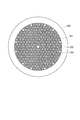
図1は、本実施形態に係る増幅用光ファイバ1の断面図である。この図は、増幅用光ファイバ1のファイバ軸に垂直な断面を示している。この図に示される増幅用光ファイバ1は、励起光により励起されて所定波長帯域において利得を有する光学活性元素が添加されたコア領域10と、このコア領域10を取り囲むクラッド領域20とを備える。コア領域10に添加される光学活性元素は、希土類元素や遷移金属元素等であり、好適にはEr元素やTm元素等の希土類元素である。
FIG. 1 is a cross-sectional view of an amplification
増幅用光ファイバ1は、ファイバ軸に垂直なクラッド領域20の断面において屈折率分布が2次元周期構造を有し、その2次元周期構造の中心の欠陥によりコア領域10が形成され、ファイバ軸方向に沿って同一の断面形状を維持している。また、増幅用光ファイバ1は、クラッド領域20の断面における屈折率分布の2次元周期構造に由来する透過帯域および遮断帯域を有し、コア領域10により導波されてファイバ軸方向に沿って進むコア導波モードが透過帯域に存在する。
The amplifying
そして、増幅用光ファイバ1において励起光により励起された前記光学活性元素が利得を有する帯域は、遮断帯域と重なり増幅用光ファイバ1全体として損失を有する第一利得帯域と、透過帯域と重なり増幅用光ファイバ1全体として利得を有する第二利得帯域とを含む。
The band in which the optically active element excited by the pumping light in the amplification
具体的には、クラッド領域20の断面における屈折率分布の2次元周期構造は、2次元三角格子の各格子点上に配置された高屈折率領域21と、略均一の屈折率を有する低屈折率領域22とからなる。断面の中央において高屈折率領域21が欠けている領域がコア領域10となる。高屈折率領域21の屈折率は、低屈折率領域22の屈折率と比べて高い。例えば、高屈折率領域21は、Ge,Cl,Ti,Alのうち少なくとも1種の元素が添加されたシリカガラスからなる。また、低屈折率領域22は、純シリカガラスまたはF,B,Clのうち少なくとも1種の元素が添加されたシリカガラスからなる。
Specifically, the two-dimensional periodic structure of the refractive index distribution in the cross section of the
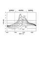
図2は、本実施形態に係る増幅用光ファイバ1の損失スペクトルの一例を示す図である。この図において、実線は増幅用光ファイバ1の励起されていない状態での添加物(Er3+)による吸収を除いた全損失を示し、破線は添加物による吸収を除いた材料損失を示す。増幅用光ファイバ1の全損失は、材料損失および曲げ損失に加えて、クラッド領域20の断面における屈折率分布の2次元周期構造に基づく不連続な損失を含む。また、フォトニックバンドギャップ効果によって光が導波される場合は、増幅用光ファイバ1の全損失は閉じ込め損をも含む。2次元周期構造に基づく損失は、光の波長だけでなく、屈折率や、2次元周期構造のピッチや外径などのパラメータによって決定される。この図に示されるように、増幅用光ファイバ1の損失スペクトルにおいては、透過帯域と遮断帯域とが交互に存在し、両帯域の透過率の差は1m程度のサンプルの透過率測定で通常15〜50dBである。
FIG. 2 is a diagram illustrating an example of a loss spectrum of the amplification
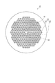
図1に示される増幅用光ファイバ1は例えばスタックアンドドロー法などにより容易に製造され得る。図3は、スタックアンドドロー法による増幅用光ファイバ1の製造方法の一例を説明する図である。スタックアンドドロー法では、同図に示されるように各種のロッド101〜103をジャケット管100内に規則的に配列したプリフォームを用意し、これをコラプス後線引または直接線引することで、図1に示されるような断面構造を持つ増幅用光ファイバ1が得られる。
The amplification
ロッド101,102それぞれの直径は互いに等しい。1本のロッド101の周りに多数のロッド102が三角格子状に規則正しく配置され、これらがジャケット管100内に挿入されるとともに、これらとジャケット管100との隙間を埋めるようにロッド103が挿入される。
The diameters of the
ロッド101は、直近のロッド102の一部とともに線引後にコア領域10となるべきもので、光学活性元素が添加されている。ロッド102,103は、線引後にクラッド領域29となるべきものである。そのうち、ロッド102の中心部は線引後に高屈折率領域21となるべき領域であり、これの周囲の部分は線引後に低屈折率領域22となるべき領域である。これらのロッド101〜103は、通常の光ファイバ母材の製造方法と同様の方法(例えばMCVD法やOVD法やコラップス法など)により製造され、また、必要に応じて外周が機械研削またはHFエッチングされる。
The
図4および図5それぞれは、反転分布率の各値について利得スペクトルの一例を示す図である。この図は、Er元素およびAl元素が添加されたシリカガラスからなるコア領域10による利得を、40%〜90%の範囲内の各反転分布率について示す。
FIG. 4 and FIG. 5 are diagrams showing an example of the gain spectrum for each value of the inversion distribution rate. This figure shows the gain by the core area |
図4に示される例では、増幅用光ファイバ1は、Sバンド(1460〜1530nm)のうちの少なくとも一部帯域が透過帯域であってコア導波基底モードを有し、遮断帯域が波長1530nmを含む。具体的には、増幅用光ファイバ1は、波長1525nm付近に透過帯域の長波長側境界が存在し、且つ、励起光波長である980nmが透過帯に入るよう、パラメータが調整されている。このような増幅用光ファイバ1を用いてSバンドで高い利得を得ようとする場合は、高い反転分布率が必要であるが、同時に波長1530nm付近の利得が大きくなり多くのASE光が発生して成長することが知られている。図4中に点線で示した波長の付近に透過帯域と損失帯域との境界を設定することで、このASE光をカットすることが可能で、反転分布率を高い条件でも使用できるようになる。
In the example shown in FIG. 4, the amplification
図5に示される例では、増幅用光ファイバ1は、Lバンド(1565〜1625nm)のうちの少なくとも一部帯域が透過帯域であってコア導波基底モードを有し、遮断帯域が波長1530nmを含む。具体的には、増幅用光ファイバ1は、波長1565nm付近に透過帯域と遮断帯域との境界が設定されている。励起光波長を980nmとする場合は気にしなくても良いが、励起光波長を1480nmとする場合はこれが透過帯に含まれるように、短波長側の境界も設計される。通常のLバンド増幅では反転分布率を低く設定することで、Lバンドの広い帯域で増幅させることが良く行われるが、利得は全般に低い。しかし、この例の増幅用光ファイバ1を用いて、反転分布率を高くした状態で、波長1530nmを中心としたASE光を抑えることで、Lバンドで従来技術より大きな利得が得られる。
In the example shown in FIG. 5, the amplification
本実施形態に係る増幅用光ファイバ1は、反転分布率を高く設定したままASE光を抑制することができるので、EDFのASE光発生帯域の中心付近(1520〜1540nm)を除く帯域における光増幅やレーザ発振において、利得及びその効率の面で有利である。図4および図5に示した例の他に、例えばCバンドのうちの長波長側(1540nm以上)の帯域の信号光を光増幅する場合は、それ以下の波長のASE光を遮断することで、反転分布率を高く設定することができるので、この帯域で高い利得が得たい目的には有利である。
Since the amplification
本実施形態に係る増幅用光ファイバ1は、光学活性元素としてはEr元素に限らず、他の光活活性元素が添加されてもよい。上記の説明と同様に、ASE帯が遮断帯域と重なるようにするとともに、利得を得たい波長大域を透過帯域と重なるようにすれば良い。これによって、ASE光を抑圧しない場合に比べて高い利得が得られる。
In the amplification
本実施形態に係る増幅用光ファイバ1では、コア領域10での光導波の形態は必ずしもフォトニックバンドギャップ(PBG)効果による必要はない。図1に示されるような断面構造において、クラッド領域20のうちの低屈折率領域22の屈折率よりコア領域10の屈折率が高い場合、波長によって導波モードの実効屈折率は低屈折率領域22の屈折率より高くなって、PBGの定義から外れる。しかし、そのような場合であっても、クラッド領域20における屈折率分布の2次元周期構造に由来する不連続な透過スペクトルが得られる。
In the amplification
クラッド領域20における屈折率分布の2次元周期構造に由来する不連続な透過帯域は、長波長側から1次,2次,・・・と呼ばれる。この次数が低いと、曲げ損失が大きくなり、また、バンドギャップ導波の場合は閉じ込め損が大きくなるが、周期構造のピッチ(高屈折率領域21のピッチ)を小さく設定することができ、したがって、増幅用光ファイバ1の外径を小さくすることができる。このような関係を考慮すると、実用的には2次または3次の透過帯域を、利得を得たい帯域として使用するのが良い。
The discontinuous transmission band derived from the two-dimensional periodic structure of the refractive index distribution in the
また、上記内容との関連で、コア領域10における屈折率分布を適切に設定することにより、導波モードのフィールドを調整することも可能である。図1に示される増幅用光ファイバ1のコア径は周期構造のパラメータによって決まるが、この構造で定義されるコア径を小さくするには限界がある。一方で、励起光が光学活性元素を励起する効率を考慮すると、小さいモードフィールド径が必要な場合が想定される。
In relation to the above contents, it is also possible to adjust the waveguide mode field by appropriately setting the refractive index distribution in the
このような場合、図6に示されるように、コア領域10のうちでも中心部の内側領域11を適切な径とした上で、その内側領域11の屈折率が低屈折率領域22の屈折率より高い構造とすることで、モードフィールド径を小さくすることができる。また、このとき、コア領域10のうち内側領域11を取り囲む外側領域12のうちロッド101に由来する部分の屈折率は、低屈折率領域22の屈折率より低いのが好ましい。例えば、コア領域10のうちの内側領域11にEr元素およびAl元素を添加することで、その内側領域11の屈折率は純シリカガラスの屈折率より大きくなる。さらに、屈折率上昇剤であるGeや屈折率低下剤であるFやBの添加により、コア領域10のうちロッド101に由来する部分における屈折率分布を任意に調整することも可能である。
In such a case, as shown in FIG. 6, the
コア領域10および内側領域11それぞれの外径については、製造時に中心に挿入されるロッド101のコア/クラッド比を調整することで容易に実現できる。コア領域10のうちの外側領域12の屈折率は、低屈折率領域21の屈折率と同じであってもよいし、異なっていてもよい。この屈折率を調整することによっても導波モードのモードフィールド径を調整することができる。
The outer diameter of each of the
従来技術のEDFに見られるように、コア領域10においてEr元素が添加される領域を内側領域11に限定することも可能である。これによってパワー密度の高い領域にErイオンが限定されるので励起効率が改善される。
As seen in the prior art EDF, it is possible to limit the region to which the Er element is added in the
励起光および被増幅光それぞれのコア導波モードは実質的にはシングルモード動作することが望ましい。高次モードが存在するか否かについては計算により算出される。適切なパラメータを選択することで、シングルモード動作し得る構造は選択される。しかし、計算上では高次モードが存在する場合でも、実際には高次モードの損失が大きいことから、比較的広い波長範囲でシングルモード動作を行うことが可能である。また、特に光増幅器の場合は、増幅用光ファイバ1は、収納のために曲げて使用されることが多いが、高次モードの曲げ損が大きいので、シングルモード動作しやすくなる。
It is desirable that the core waveguide modes of the pumping light and the amplified light substantially operate in a single mode. Whether or not a higher-order mode exists is calculated by calculation. By selecting appropriate parameters, a structure capable of single mode operation is selected. However, even if a higher order mode exists in the calculation, since the loss of the higher order mode is actually large, it is possible to perform a single mode operation in a relatively wide wavelength range. In particular, in the case of an optical amplifier, the amplification
図1に示された増幅用光ファイバ1は、穴が存在せず、中実である。このような構造の増幅用光ファイバ1は、従来の光ファイバ製造技術を用いて容易に製造できる利点がある。一方で、図7に示される増幅用光ファイバ2は、クラッド領域20の断面において2次元三角格子の近接した3つの格子点(高屈折率領域21)により囲まれる領域の中心位置に微小穴(エアホール)が設けられているものであり、このような構造であっても所期の機能を果たすことができる。
The amplification
図7に示される増幅用光ファイバ2は、図3に示された状態からコラプスや線引を行う際に、加工終了端側において、予め端を塞ぐ、一定圧に保つ、およびできるだけ低温で加工を行うといった条件により、比較的容易に製造される。この構造の増幅用光ファイバ2は、エアホールが無い増幅用光ファイバ1の場合に比べて、若干損失が高くなるが、エアホールを含む低屈折率領域22と高屈折率領域21との実効的な比屈折率差が大きくなる効果があるので、曲げ損失が低下し、また、透過帯域と遮断帯域とのアイソレーションが大きくなる点において有利である。
When the amplification
増幅用光ファイバ1が光増幅器内に設置される場合、収納性の観点から増幅用光ファイバ1がコイル巻きにされることが多い。それ故、増幅用光ファイバ1は曲げ損失に強いことが要求される。図1に示される構造の増幅用光ファイバ1は、直径数十mmφコイル巻きの状態であっても曲げ損失を発生しないような設計が可能である。具体的には、周期構造のピッチΛに対する高屈折率領域21の直径dの比(d/Λ)を0.6より大きくすることで、実用上充分に低い曲げ損失が得られる。また、前述の増幅用光ファイバ2の構造のような小さなエアホールの導入や、コア領域10のうちの内側領域11の屈折率を上昇させるような設計と組み合わせれば、曲げ損失に対してさらに有利である。
When the amplification
増幅用光ファイバのコア領域にP、B、Fなどの元素を添加することで、SバンドやLバンドでの利得帯域が広がることが知られている。本実施形態に係る増幅用光ファイバ1,2でも、コア領域10にP、B、Fなどの元素を添加すれば、より広い帯域で高い利得を得ることが可能であり、また、場合によっては利得平坦性にも優れた状態で高い利得を得ることが可能である。
It is known that by adding elements such as P, B, and F to the core region of the amplification optical fiber, the gain band in the S band and the L band is widened. Even in the optical fibers for
増幅用光ファイバ1,2の背景損失(光学活性現その影響を除いた材料およびその不純物や製法に起因する損失)は、20dB/km以下であることが望ましく、より好ましく10dB/km以下であることが望ましい。このような増幅用光ファイバ1,2は、図3に示されるスタック後のプリフォームに対し、高温で塩素系ガスを含む雰囲気で加熱処理を行った後にコラプスまたは線引することで得られる。
The background loss of
光ファイバ増幅器の光増幅媒体として増幅用光ファイバ1,2を用いる場合、増幅用光ファイバ1,2と他の光ファイバとの融着接続が必要である。増幅用光ファイバ1,2は、穴がないか、あっても微小であるので、他の光ファイバとの融着接続の際に汎用の放電方式での融着損失を低く抑えることができる。但し、増幅用光ファイバ1,2は、石英ガラスに対する添加物が多いので、粘性が低い点、および、拡散する可能性がある点で、注意が必要である。汎用SMファイバの条件に比べて、増幅用光ファイバ1,2の融着の条件として放電時間および放電パワーを1/2〜1/3に抑えれば、比較的低損失(1dB以下/1箇所)で融着接続することができる。
When the amplification
1,2…増幅用光ファイバ、10…コア領域、11…内側領域、12…外側領域、20…クラッド領域、21…高屈折率領域、22…低屈折率領域。
DESCRIPTION OF
Claims (10)
前記クラッド領域は、ファイバ軸に垂直な断面において2次元周期構造でありファイバ軸に沿って一様である屈折率分布を有し、
前記コア領域は、前記2次元周期構造の前記断面中央部にある欠陥からなり、
前記増幅用光ファイバは、前記2次元周期構造に由来する透過帯域および遮断帯域を有し、前記コア領域に導波されてファイバ軸方向に進むコア導波モードが前記透過帯域に存在し、
励起光により励起された前記光学活性元素が利得を有する帯域は、前記遮断帯域と重なり前記増幅用光ファイバ全体として損失を有する第一利得帯域と前記透過帯域と重なり前記増幅用光ファイバ全体として利得を有する第二利得帯域とを含み、
前記2次元周期構造が、2次元三角格子の各格子点上に配置された高屈折率領域と、略均一の屈折率を有する低屈折率領域とからなり、
前記高屈折率領域が、Ge,Cl,Ti,Alのうち少なくとも1種の元素を添加物として含むシリカガラスからなり、
前記低屈折率領域が、純シリカガラスまたはF,B,Clのうち少なくとも1種の元素を添加物として含むシリカガラスからなる、
ことを特徴とする増幅用光ファイバ。 An amplification optical fiber comprising a core region containing an optically active element as an additive, and a cladding region surrounding the core region,
The cladding region has a two-dimensional periodic structure in a cross section perpendicular to the fiber axis and has a refractive index distribution that is uniform along the fiber axis;
The core region consists of a defect in the center of the cross section of the two-dimensional periodic structure,
The amplification optical fiber has a transmission band and a cutoff band derived from the two-dimensional periodic structure, and a core waveguide mode guided in the core region and traveling in the fiber axis direction exists in the transmission band,
The band in which the optically active element excited by pumping light has a gain overlaps with the cut-off band and overlaps with the first gain band having loss as the entire amplification optical fiber and the transmission band, and gain as the entire amplification optical fiber. A second gain band having
The two-dimensional periodic structure comprises a high refractive index region disposed on each lattice point of a two-dimensional triangular lattice and a low refractive index region having a substantially uniform refractive index;
The high refractive index region is made of silica glass containing at least one element of Ge, Cl, Ti, Al as an additive,
The low refractive index region is made of pure silica glass or silica glass containing at least one element of F, B, and Cl as an additive,
An optical fiber for amplification characterized by the above.
前記光学活性元素がEr元素であり、前記コア領域にAl元素が共添加物として含み、
Lバンド(1565〜1625nm)のうちの少なくとも一部帯域が前記透過帯域であってコア導波基底モードを有し、
前記遮断帯域が波長1530nmを含む、
ことを特徴とする請求項9記載の増幅用光ファイバ。 The main component is silica glass,
The optically active element is an Er element, and the core region includes an Al element as a co-additive,
At least a part of the L band (1555-1625 nm) is the transmission band and has a core waveguide fundamental mode,
The stopband includes a wavelength of 1530 nm;
The amplification optical fiber according to claim 9.
Priority Applications (1)
| Application Number | Priority Date | Filing Date | Title |
|---|---|---|---|
| JP2012060646A JP2012114476A (en) | 2012-03-16 | 2012-03-16 | Optical fiber for amplification |
Applications Claiming Priority (1)
| Application Number | Priority Date | Filing Date | Title |
|---|---|---|---|
| JP2012060646A JP2012114476A (en) | 2012-03-16 | 2012-03-16 | Optical fiber for amplification |
Related Parent Applications (1)
| Application Number | Title | Priority Date | Filing Date |
|---|---|---|---|
| JP2007241300A Division JP2009076493A (en) | 2007-09-18 | 2007-09-18 | Optical fiber for amplification |
Publications (1)
| Publication Number | Publication Date |
|---|---|
| JP2012114476A true JP2012114476A (en) | 2012-06-14 |
Family
ID=46498273
Family Applications (1)
| Application Number | Title | Priority Date | Filing Date |
|---|---|---|---|
| JP2012060646A Pending JP2012114476A (en) | 2012-03-16 | 2012-03-16 | Optical fiber for amplification |
Country Status (1)
| Country | Link |
|---|---|
| JP (1) | JP2012114476A (en) |
Citations (3)
| Publication number | Priority date | Publication date | Assignee | Title |
|---|---|---|---|---|
| WO2003019257A1 (en) * | 2001-08-30 | 2003-03-06 | Crystal Fibre A/S | Optical fibre with high numerical aperture, method of its production, and use thereof |
| WO2005003828A1 (en) * | 2003-07-04 | 2005-01-13 | Mitsubishi Cable Industries, Ltd. | Photonic crystal fiber |
| WO2007057024A2 (en) * | 2005-11-18 | 2007-05-24 | Crystal Fibre A/S | Improved active optical fibers with wavelength-selective filtering mechanism, method of production and their use |
-
2012
- 2012-03-16 JP JP2012060646A patent/JP2012114476A/en active Pending
Patent Citations (3)
| Publication number | Priority date | Publication date | Assignee | Title |
|---|---|---|---|---|
| WO2003019257A1 (en) * | 2001-08-30 | 2003-03-06 | Crystal Fibre A/S | Optical fibre with high numerical aperture, method of its production, and use thereof |
| WO2005003828A1 (en) * | 2003-07-04 | 2005-01-13 | Mitsubishi Cable Industries, Ltd. | Photonic crystal fiber |
| WO2007057024A2 (en) * | 2005-11-18 | 2007-05-24 | Crystal Fibre A/S | Improved active optical fibers with wavelength-selective filtering mechanism, method of production and their use |
Similar Documents
| Publication | Publication Date | Title |
|---|---|---|
| JP6794310B2 (en) | Multi-core erbium-doped fiber amplifier | |
| US8428409B2 (en) | Filter fiber for use in Raman lasing applications and techniques for manufacturing same | |
| US8564877B2 (en) | Photonic bandgap fiber and fiber amplifier | |
| JP5238509B2 (en) | Photonic bandgap fiber | |
| US7340140B1 (en) | Er/Yb double clad photonic crystal fiber | |
| JP6348535B2 (en) | High power double clad (DC) pump erbium-doped fiber amplifier (EDFA) | |
| JP2010129886A (en) | Optical fiber for fiber laser, and fiber laser | |
| US9653870B1 (en) | Rare-earth doped gain fibers | |
| JP2003124547A (en) | Optical fiber amplifier | |
| AU768232B2 (en) | Optical fiber for optical amplification and optical fiber amplifier | |
| US9640936B1 (en) | Rare-earth doped gain fibers | |
| JP2009076493A (en) | Optical fiber for amplification | |
| JP2008226885A (en) | Rare earth doped photonic band gap fiber and optical amplifier | |
| JP4823633B2 (en) | Fiber laser | |
| JP2010080884A (en) | Optical fiber amplifier | |
| JP2012114476A (en) | Optical fiber for amplification | |
| US8116607B2 (en) | Rare-earth doped optical fiber, method of producing the same, and fiber laser | |
| WO2022157896A1 (en) | Optical fiber amplifier | |
| Maruyama et al. | High-power Yb-doped solid-core photonic bandgap fiber amplifier at 1150-1200nm | |
| JP2004247466A (en) | Hybrid optical fiber amplifier | |
| WO2022216780A1 (en) | Methods of increasing higher-order mode suppression in large-mode area ring fibers and systems thereof | |
| CN117673874A (en) | High-power fiber laser and application method thereof | |
| Coscelli et al. | Anti-symmetric hybrid photonic crystal fibers with enhanced filtering and bending properties | |
| JP2003092448A (en) | Optical amplifying fiber and device thereof | |
| JP2009116010A (en) | Method of designing raman amplifying optical fiber, raman amplifying optical fiber and raman amplifier |
Legal Events
| Date | Code | Title | Description |
|---|---|---|---|
| A621 | Written request for application examination |
Free format text: JAPANESE INTERMEDIATE CODE: A621 Effective date: 20120330 |
|
| A977 | Report on retrieval |
Free format text: JAPANESE INTERMEDIATE CODE: A971007 Effective date: 20130612 |
|
| A131 | Notification of reasons for refusal |
Free format text: JAPANESE INTERMEDIATE CODE: A131 Effective date: 20130702 |
|
| A02 | Decision of refusal |
Free format text: JAPANESE INTERMEDIATE CODE: A02 Effective date: 20131029 |