JP2012111418A - Electric power steering device - Google Patents

Electric power steering device Download PDF

Info

Publication number
JP2012111418A
JP2012111418A JP2010263811A JP2010263811A JP2012111418A JP 2012111418 A JP2012111418 A JP 2012111418A JP 2010263811 A JP2010263811 A JP 2010263811A JP 2010263811 A JP2010263811 A JP 2010263811A JP 2012111418 A JP2012111418 A JP 2012111418A
Authority
JP
Japan
Prior art keywords
adjustment pin
insertion hole
shaft
housing
bolt
Prior art date
Legal status (The legal status is an assumption and is not a legal conclusion. Google has not performed a legal analysis and makes no representation as to the accuracy of the status listed.)
Granted
Application number
JP2010263811A
Other languages
Japanese (ja)
Other versions
JP5644426B2 (en
Inventor
Yuuki Bando
勇気 坂東
Current Assignee (The listed assignees may be inaccurate. Google has not performed a legal analysis and makes no representation or warranty as to the accuracy of the list.)
JTEKT Corp
Original Assignee
JTEKT Corp
Priority date (The priority date is an assumption and is not a legal conclusion. Google has not performed a legal analysis and makes no representation as to the accuracy of the date listed.)
Filing date
Publication date
Application filed by JTEKT Corp filed Critical JTEKT Corp
Priority to JP2010263811A priority Critical patent/JP5644426B2/en
Publication of JP2012111418A publication Critical patent/JP2012111418A/en
Application granted granted Critical
Publication of JP5644426B2 publication Critical patent/JP5644426B2/en
Expired - Fee Related legal-status Critical Current
Anticipated expiration legal-status Critical

Links

Images

Abstract

PROBLEM TO BE SOLVED: To provide an electric power steering device capable of preventing a lowering in belt tension.SOLUTION: A belt tension adjustment mechanism of the EPS has a circular adjustment pin insertion hole 51a in a second motor attachment part 51 of an end housing 13. Further, the belt tension adjustment mechanism has an adjustment pin 55 inserted to the adjustment pin insertion hole 51a. A cylindrical shaft part 56 which is rotatably inserted and supported by an adjustment pin insertion hole 51a is formed on the adjustment pin 55 and a through-hole 58 to which a second bolt 53 is inserted is formed on a position off-centered from the center C2 of the shaft part 56.

Description

本発明は、モータの動力を、ステアリング操作を補助するためのアシスト力としてラック軸に付与する電動パワーステアリング装置に関する。   The present invention relates to an electric power steering apparatus that applies power of a motor to a rack shaft as an assist force for assisting a steering operation.

この種の電動パワーステアリング装置(EPS)としては、例えば、特許文献1が挙げられる。特許文献1の電動パワーステアリング装置において、ラック軸が収容されたギヤハウジングには、電動モータがカラー(エンドハウジング)を介して固定されている。そして、電動モータの駆動により発生する動力は、ベルト式伝動機構を介してラック軸に伝達されるようになっている。図5の模式図に示すように、ベルト式伝動機構は、電動モータ90により回転駆動される入力プーリ91と、ラック軸にボールねじ機構を介して連結される出力プーリ92と、入力プーリ91及び出力プーリ92に掛け渡されたベルト93と、からなる。   As this kind of electric power steering device (EPS), for example, Patent Document 1 is cited. In the electric power steering apparatus of Patent Document 1, an electric motor is fixed to a gear housing in which a rack shaft is accommodated via a collar (end housing). The power generated by the driving of the electric motor is transmitted to the rack shaft via the belt type transmission mechanism. As shown in the schematic diagram of FIG. 5, the belt-type transmission mechanism includes an input pulley 91 that is rotationally driven by an electric motor 90, an output pulley 92 that is connected to the rack shaft via a ball screw mechanism, an input pulley 91, and A belt 93 wound around an output pulley 92.

また、電動パワーステアリング装置は、ベルト93の張力調整部(ベルトの張力調整機構)を備える。この張力調整部は、カラー94の一対の結合部位95それぞれに形成されたボルト挿通孔95a,95bより構成される。2つのボルト挿通孔95a,95bのうち一方(図5では左方)のボルト挿通孔95aは円孔状に形成され、他方(図5では右方)のボルト挿通孔95bは上下方向に延びる長孔状に形成されている。各ボルト挿通孔95a,95bに挿通された調整ボルトB(図5では、他方のボルト挿通孔95bに挿通された調整ボルトBのみ図示)は、ギヤハウジングに螺合される。   Further, the electric power steering apparatus includes a belt 93 tension adjusting section (belt tension adjusting mechanism). The tension adjusting portion is configured by bolt insertion holes 95 a and 95 b formed in the pair of coupling portions 95 of the collar 94. One of the two bolt insertion holes 95a and 95b (left side in FIG. 5) is formed in a circular hole shape, and the other (right side in FIG. 5) bolt insertion hole 95b extends in the vertical direction. It is formed in a hole shape. Adjustment bolts B inserted into the respective bolt insertion holes 95a and 95b (in FIG. 5, only the adjustment bolt B inserted into the other bolt insertion hole 95b is shown) are screwed into the gear housing.

そして、ベルト93の張力調整は、円孔状のボルト挿通孔95aを揺動支点として、カラー94をギヤハウジングに対して揺動させる。このとき、カラー94は、長孔状のボルト挿通孔95bの長さにより許容される調整域T内において揺動される。そして、カラー94の揺動により、入力プーリ91の回転中心線91aと、出力プーリ92の回転中心線92aとの距離Dが調整され、ベルト93の張力が適切に調整されたならば、各調整ボルトBをギヤハウジングに螺合することで、ベルト93の張力調整が完了する。   The tension of the belt 93 is adjusted by causing the collar 94 to swing with respect to the gear housing with the circular bolt insertion hole 95a as a swing fulcrum. At this time, the collar 94 is swung within an adjustment region T that is allowed by the length of the long hole-like bolt insertion hole 95b. When the distance D between the rotation center line 91a of the input pulley 91 and the rotation center line 92a of the output pulley 92 is adjusted by the swing of the collar 94 and the tension of the belt 93 is adjusted appropriately, each adjustment is performed. The tension adjustment of the belt 93 is completed by screwing the bolt B into the gear housing.

特開2005−343434号公報JP 2005-343434 A

ところで、入力プーリ91は、ベルト93の張力により出力プーリ92側へ常時引張られている。そして、特許文献1の電動パワーステアリング装置においては、長孔状のボルト挿通孔95bの長さ方向が、入力プーリ91が出力プーリ92側へ引張られる方向に延びている。このため、ベルト93の張力により、電動モータ90が長孔状のボルト挿通孔95bに沿って出力プーリ92側へ引き寄せられ、ベルト93が緩んで張力が低下してしまうという問題があった。   By the way, the input pulley 91 is always pulled toward the output pulley 92 by the tension of the belt 93. In the electric power steering device of Patent Document 1, the length direction of the long hole-like bolt insertion hole 95b extends in the direction in which the input pulley 91 is pulled toward the output pulley 92 side. For this reason, there is a problem that the tension of the belt 93 causes the electric motor 90 to be drawn toward the output pulley 92 side along the elongated hole insertion hole 95b, and the belt 93 is loosened and the tension is lowered.

本発明は、上記問題点を解決するためになされたものであって、その目的は、ベルト張力の低下を防止することができる電動パワーステアリング装置を提供することにある。   The present invention has been made to solve the above problems, and an object of the present invention is to provide an electric power steering apparatus capable of preventing a decrease in belt tension.

上記問題点を解決するために、請求項1に記載の発明は、ラック軸を収容するハウジングには、該ハウジングを貫通した固定部材がモータに固定されることにより前記モータが固定され、前記モータの駆動により発生する動力を該モータの出力軸からベルトを介して前記ラック軸に伝達し、前記動力を、ステアリング操作を補助するためのアシスト力として前記ラック軸に付与する電動パワーステアリング装置において、前記ベルトの張力調整機構として、円形状の調整ピン挿通孔を前記ハウジングに有するとともに、前記調整ピン挿通孔に挿通される調整ピンを有しており、前記調整ピンに、前記調整ピン挿通孔に回転可能に挿通支持される軸部が形成されるとともに、前記軸部の中心から偏心した位置に、前記固定部材を前記モータに固定するために該固定部材が挿通される貫通孔が形成されていることを要旨とする。   In order to solve the above-described problems, the invention according to claim 1 is directed to a housing that accommodates a rack shaft, and a fixing member that penetrates the housing is fixed to the motor so that the motor is fixed. In the electric power steering apparatus that transmits the power generated by the driving of the motor to the rack shaft through a belt from the output shaft of the motor, and applies the power to the rack shaft as an assisting force for assisting a steering operation. As the belt tension adjustment mechanism, the housing has a circular adjustment pin insertion hole in the housing and an adjustment pin inserted into the adjustment pin insertion hole. The adjustment pin is inserted into the adjustment pin insertion hole. A shaft portion that is rotatably inserted and supported is formed, and the fixing member is fixed to the motor at a position eccentric from the center of the shaft portion. The fixing member is summarized in that the through hole is inserted is formed to.

上記発明によれば、調整ピンを調整ピン挿通孔内で回転させると、固定部材が軸部の中心を回転中心として公転し、この公転に伴い固定部材が固定されたモータも移動する。このため、モータの出力軸がラック軸に対し移動し、両軸間の距離が変化する結果、ベルト張力が調整される。ベルト張力を調整した状態では、ベルト張力により、モータの出力軸にはラック軸側への引寄せ力が作用するとともに、そのモータをハウジングに固定する固定部材にもラック軸側への引寄せ力が作用している。このとき、固定部材は調整ピンに挿通支持され、その調整ピンは円形状の調整ピン挿通孔に挿通支持されており、引寄せ力によって引寄せられる側に位置する調整ピンの端面は、調整ピン挿通孔の内面に当接し、常時支持されている。このため、固定部材に引寄せ力が作用していても固定部材がラック軸側へ移動することが防止され、ベルト張力の低下が防止される。   According to the above invention, when the adjustment pin is rotated in the adjustment pin insertion hole, the fixing member revolves around the center of the shaft portion, and the motor to which the fixing member is fixed moves along with the revolution. For this reason, the output shaft of the motor moves relative to the rack shaft, and the distance between the two shafts changes, so that the belt tension is adjusted. When the belt tension is adjusted, the belt tension causes a pulling force to the rack shaft side to act on the motor output shaft, and the pulling force to the rack shaft side also to the fixing member that fixes the motor to the housing. Is working. At this time, the fixing member is inserted and supported by the adjustment pin, and the adjustment pin is inserted and supported by the circular adjustment pin insertion hole. The end face of the adjustment pin located on the side attracted by the drawing force is the adjustment pin. It contacts the inner surface of the insertion hole and is always supported. For this reason, even if a pulling force is applied to the fixing member, the fixing member is prevented from moving toward the rack shaft, and a decrease in belt tension is prevented.

請求項2に記載の発明は、請求項1に記載の電動パワーステアリング装置において、前記軸部の軸方向一端には、該軸部より大径をなす頭部が形成されていることを要旨とする。   The invention according to claim 2 is the electric power steering device according to claim 1, wherein a head having a diameter larger than that of the shaft portion is formed at one axial end of the shaft portion. To do.

上記発明によれば、頭部を操作することで、調整ピンを容易に回転させることができる。
請求項3に記載の発明は、請求項2に記載の電動パワーステアリング装置において、前記頭部及び前記ハウジングのいずれか一方には掛止部が形成されるとともに、他方には前記固定部材の前記モータへの固定に伴い前記掛止部が掛止する被掛止部が形成されていることを要旨とする。
According to the said invention, an adjustment pin can be easily rotated by operating a head.
According to a third aspect of the present invention, in the electric power steering apparatus according to the second aspect, a latching portion is formed on one of the head and the housing, and the fixing member is on the other. The gist of the invention is that a hooked portion for hooking the hooking portion is formed along with the fixing to the motor.

上記発明によれば、掛止部の被掛止部に対する掛止により、調整ピンの回転を防止して、調整ピンの回転に伴う固定部材の移動を防止することができる。
請求項4に記載の発明は、請求項1〜請求項3のうちいずれか一項に記載の電動パワーステアリング装置において、前記ハウジングには、前記固定部材とは別の固定部材が挿通される挿通孔が形成されるとともに、該挿通孔は長孔状に形成されていることを要旨とする。
According to the above invention, the adjustment pin can be prevented from rotating by the latching of the latching portion with respect to the latched portion, and the fixing member can be prevented from moving due to the rotation of the adjustment pin.
According to a fourth aspect of the present invention, in the electric power steering apparatus according to any one of the first to third aspects, the housing is inserted with a fixing member different from the fixing member. The gist is that a hole is formed and the insertion hole is formed in a long hole shape.

上記発明によれば、ベルトの張力調整の際、調整ピンを回転させモータを移動させると、別の固定部材が、挿通孔の長さ方向へ移動する。よって、挿通孔の長さ分だけモータの移動が許され、ベルト張力を調整することができる。   According to the above invention, when adjusting the belt tension, when the adjustment pin is rotated and the motor is moved, the other fixing member moves in the length direction of the insertion hole. Therefore, the motor is allowed to move by the length of the insertion hole, and the belt tension can be adjusted.

請求項5に記載の発明は、請求項4に記載の電動パワーステアリング装置において、前記ハウジングには前記出力軸が挿通される出力軸収容孔が形成されるとともに、前記ラック軸が挿通されるラック軸収容孔が形成され、前記出力軸収容孔とラック軸収容孔の中心軸同士を結ぶ直線を中央線とすると、前記挿通孔は、該挿通孔の中心線が前記中央線に対し交差するように形成されていることを要旨とする。   According to a fifth aspect of the present invention, in the electric power steering apparatus according to the fourth aspect, the housing is formed with an output shaft receiving hole through which the output shaft is inserted, and the rack through which the rack shaft is inserted. A shaft housing hole is formed, and a straight line connecting the center shafts of the output shaft housing hole and the rack shaft housing hole is defined as a center line, the center line of the insertion hole intersects the center line. The gist is that it is formed.

上記発明によれば、出力軸に対し、ベルトの張力に基づくラック軸側への引寄せ力が作用しても、挿通孔内面が別の固定部材に接触して、モータの移動を抑制し、ベルトの張力低下の防止に貢献することができる。   According to the above invention, even if a pulling force to the rack shaft side based on the belt tension acts on the output shaft, the inner surface of the insertion hole comes into contact with another fixing member to suppress the movement of the motor, This can contribute to prevention of belt tension drop.

本発明によれば、ベルト張力の低下を防止することができる。   According to the present invention, it is possible to prevent a decrease in belt tension.

電動パワーステアリング装置の概略構成図。The schematic block diagram of an electric power steering apparatus. (a)はベルトの張力調整機構を示す分解斜視図、(b)は調整ピンを示す斜視図。(A) is a disassembled perspective view which shows the tension adjustment mechanism of a belt, (b) is a perspective view which shows an adjustment pin. (a)〜(c)は調整ピンを回転させてベルト張力を調整した状態の正面図。(A)-(c) is a front view of the state which adjusted the belt tension by rotating the adjustment pin. ベルトの張力調整機構を示す図3(b)の4−4線断面図。FIG. 4B is a cross-sectional view taken along line 4-4 of FIG. 背景技術を示す模式図。The schematic diagram which shows background art.

以下、本発明を具体化した一実施形態を図1〜図4にしたがって説明する。
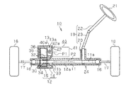
図1に示すように、電動パワーステアリング装置(EPS)10において、ラック軸11が挿通されるハウジング12は、ラック軸11のほぼ全体が収容される略円筒状の第1ハウジング14と、ラック軸11の一部が収容される略円筒状の第2ハウジング15とを接合して形成されている。また、第1ハウジング14の第2ハウジング15側外周面には、モータとしての電動モータ40をハウジング12に固定するためのエンドハウジング13が形成されている。
Hereinafter, an embodiment embodying the present invention will be described with reference to FIGS.
As shown in FIG. 1, in an electric power steering apparatus (EPS) 10, a housing 12 into which a rack shaft 11 is inserted includes a substantially cylindrical first housing 14 in which almost the entire rack shaft 11 is accommodated, and a rack shaft. 11 is formed by joining a substantially cylindrical second housing 15 in which a part of 11 is accommodated. An end housing 13 for fixing the electric motor 40 as a motor to the housing 12 is formed on the outer peripheral surface of the first housing 14 on the second housing 15 side.

ハウジング12内において、ラック軸11の両端には、ラックエンド16を介してタイロッド17が連結されている。なお、本実施形態のラックエンド16には、周知のボールジョイントが用いられている。そして、タイロッド17の先端は、転舵輪18を支承するナックル(図示略)に連結されている。   In the housing 12, tie rods 17 are connected to both ends of the rack shaft 11 via rack ends 16. A known ball joint is used for the rack end 16 of the present embodiment. The tip of the tie rod 17 is connected to a knuckle (not shown) that supports the steered wheel 18.

また、ハウジング12内には、ステアリングシャフト19の基端側を構成するピニオン軸20がラック軸11と交差する状態で回転自在に支承されている。なお、本実施形態のステアリングシャフト19は、ピニオン軸20、及び一端にステアリング21が設けられたコラムシャフト22、並びにピニオン軸20とコラムシャフト22を接続するインターミディエイトシャフト23により構成されている。そして、ラック軸11の周面に形成されたラック歯11aは、このピニオン軸20と噛合されている。   In the housing 12, a pinion shaft 20 constituting the proximal end side of the steering shaft 19 is rotatably supported in a state of intersecting with the rack shaft 11. The steering shaft 19 according to the present embodiment includes a pinion shaft 20, a column shaft 22 provided with a steering 21 at one end, and an intermediate shaft 23 that connects the pinion shaft 20 and the column shaft 22. The rack teeth 11 a formed on the peripheral surface of the rack shaft 11 are meshed with the pinion shaft 20.

すなわち、ラック軸11は、周知のラック&ピニオン機構24を介してステアリングシャフト19と連結されており、ステアリング21の操作に伴うステアリングシャフト19の回転は、このラック&ピニオン機構24によりラック軸11の往復動に変換される。そして、ラック軸11の軸方向への移動により、転舵輪18の舵角が変更される。   That is, the rack shaft 11 is connected to the steering shaft 19 via a well-known rack and pinion mechanism 24, and the rotation of the steering shaft 19 due to the operation of the steering 21 is performed by the rack and pinion mechanism 24. Converted to reciprocating motion. And the rudder angle of the steered wheel 18 is changed by the movement of the rack shaft 11 in the axial direction.

本実施形態のEPS10は、ボール螺子装置30を用いて電動モータ40の回転(動力)をラック軸11の往復動に変換することにより、操舵系にアシスト力を付与する所謂ラックアシスト型のEPSとして構成されている。より詳しくは、電動モータ40の出力軸40aと、ラック軸11とが互いの回転中心線P1,P2がほぼ平行となるようにハウジング12に対し電動モータ40が配置されたラックパラレル型のEPSとして構成されている。   The EPS 10 of the present embodiment is a so-called rack assist type EPS that applies assist force to the steering system by converting the rotation (power) of the electric motor 40 into reciprocation of the rack shaft 11 using the ball screw device 30. It is configured. More specifically, as a rack parallel type EPS in which the electric motor 40 is disposed with respect to the housing 12 so that the output shaft 40a of the electric motor 40 and the rack shaft 11 are substantially parallel to each other in the rotation center lines P1 and P2. It is configured.

ラック軸11は、その外周に螺子溝が螺刻された螺子部11bを形成することにより、螺子軸として構成されている。そして、ボール螺子装置30は、この螺子部11bに複数のボール32を介してボール螺子ナット33を螺合することにより形成されている。   The rack shaft 11 is configured as a screw shaft by forming a screw portion 11b having a screw groove formed on the outer periphery thereof. The ball screw device 30 is formed by screwing a ball screw nut 33 to the screw portion 11b via a plurality of balls 32.

また、ボール螺子ナット33は、従動プーリ34と一体回転可能に構成されるとともに、この従動プーリ34の径方向外側には、ベルト35を介して駆動連結された駆動プーリ36が並列配置されている。そして、電動モータ40の出力軸40aには駆動プーリ36が連結されるとともに、この駆動プーリ36と従動プーリ34にはベルト35が掛け渡されている。電動モータ40における出力軸40aの回転動力は、駆動プーリ36、ベルト35、及び従動プーリ34を介してボール螺子ナット33に伝達されるとともに、ボール螺子ナット33のラック軸11に対する相対回転がラック軸11の往復動に変換される。したがって、本実施形態のEPS10は、従動プーリ34、ベルト35、及び駆動プーリ36からなるベルト式伝達機構を介して、モータトルクに基づく軸方向の押圧力(駆動力)を、ステアリング操作を補助するためのアシスト力(補助操舵力)として操舵系に付与する構成になっている。   The ball screw nut 33 is configured to be rotatable integrally with the driven pulley 34, and a drive pulley 36 that is drivingly connected via a belt 35 is arranged in parallel on the radially outer side of the driven pulley 34. . A drive pulley 36 is connected to the output shaft 40 a of the electric motor 40, and a belt 35 is stretched between the drive pulley 36 and the driven pulley 34. The rotational power of the output shaft 40a in the electric motor 40 is transmitted to the ball screw nut 33 through the drive pulley 36, the belt 35, and the driven pulley 34, and the relative rotation of the ball screw nut 33 with respect to the rack shaft 11 is reduced to the rack shaft. 11 reciprocating motions. Therefore, the EPS 10 of the present embodiment assists the steering operation with the axial pressing force (driving force) based on the motor torque via the belt-type transmission mechanism including the driven pulley 34, the belt 35, and the driving pulley 36. Therefore, it is configured to apply to the steering system as an assist force (auxiliary steering force).

次に、本実施形態のEPS10におけるベルト35の張力調整機構について説明する。
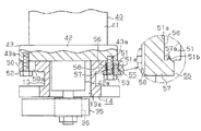
まず、電動モータ40側のベルト張力調整機構について説明する。図2(a)に示すように、電動モータ40において、モータハウジング41からの出力軸40aの突出側端面には、エンドプレート42が接合されている。このエンドプレート42の一端面には、出力軸40aを回転可能に支持する円筒状の支持部42aが突設されるとともに、エンドプレート42には、板状をなす一対のフランジ部43が支持部42aより外方へ延設されている。各フランジ部43それぞれにはネジ孔43aが形成されている。
Next, the tension adjusting mechanism of the belt 35 in the EPS 10 of the present embodiment will be described.
First, the belt tension adjusting mechanism on the electric motor 40 side will be described. As shown in FIG. 2A, in the electric motor 40, an end plate 42 is joined to the projecting side end surface of the output shaft 40 a from the motor housing 41. A cylindrical support portion 42a that rotatably supports the output shaft 40a is projected on one end face of the end plate 42, and a pair of flange portions 43 that form a plate shape are supported on the end plate 42. It extends outward from 42a. Each flange portion 43 is formed with a screw hole 43a.

次に、第1ハウジング14側のベルト35の張力調整機構について説明する。
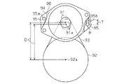
図2(a)及び図3(a)に示すように、第1ハウジング14には、ラック軸11が収容されるラック軸収容孔14aが形成されるとともに、エンドハウジング13には、電動モータ40の出力軸40aが収容される出力軸収容孔13aが形成されている。また、第1ハウジング14において、エンドハウジング13の外周面には、それぞれ板状をなす第1モータ取付部50(図2(a)及び図3(a)では左側)と第2モータ取付部51(図2(a)及び図3(a)では右側)が、出力軸収容孔13aを挟んで互いに相反する方向へ延びるように形成されている。第1モータ取付部50には、長孔状をなす挿通孔としてのボルト挿通孔50aが形成されている。
Next, the tension adjusting mechanism of the belt 35 on the first housing 14 side will be described.
As shown in FIGS. 2A and 3A, the first housing 14 is formed with a rack shaft housing hole 14a for housing the rack shaft 11, and the end housing 13 has an electric motor 40. The output shaft accommodating hole 13a for accommodating the output shaft 40a is formed. In the first housing 14, a plate-shaped first motor mounting portion 50 (left side in FIGS. 2A and 3A) and a second motor mounting portion 51 are formed on the outer peripheral surface of the end housing 13. (The right side in FIG. 2A and FIG. 3A) is formed so as to extend in directions opposite to each other across the output shaft accommodation hole 13a. The first motor mounting portion 50 is formed with a bolt insertion hole 50a as an insertion hole having a long hole shape.

ここで、第1ハウジング14において、出力軸収容孔13aの中心軸L1と、ラック軸収容孔14aの中心軸L2とを結ぶ仮想線(直線)を、第1ハウジング14の中央線Cとする。この場合、ボルト挿通孔50aの長さ方向に延びる中心線Nは、上記中央線Cに対して斜めに交差するようになっている。そして、ボルト挿通孔50aには、電動モータ40を固定するための別の固定部材としての第1ボルト52が挿通されるとともに、ボルト挿通孔50aを介して第1モータ取付部50(ハウジング12)を貫通した第1ボルト52は電動モータ40のネジ孔43aに螺合されようになっている。   Here, in the first housing 14, a virtual line (straight line) connecting the central axis L1 of the output shaft accommodating hole 13a and the central axis L2 of the rack shaft accommodating hole 14a is defined as a central line C of the first housing 14. In this case, the center line N extending in the length direction of the bolt insertion hole 50a intersects the center line C obliquely. A first bolt 52 as another fixing member for fixing the electric motor 40 is inserted into the bolt insertion hole 50a, and the first motor mounting portion 50 (housing 12) is inserted through the bolt insertion hole 50a. The first bolt 52 penetrating through is screwed into the screw hole 43 a of the electric motor 40.

第2モータ取付部51には、円孔状をなす調整ピン挿通孔51aが形成されている。また、第2モータ取付部51において、調整ピン挿通孔51aの周囲には、被掛止部としての掛止凹部51bが、調整ピン挿通孔51aを取り囲むように円環状に形成されている。   The second motor mounting portion 51 is formed with a circular adjustment pin insertion hole 51a. Further, in the second motor mounting portion 51, a latching recess 51b as a hooked portion is formed in an annular shape around the adjustment pin insertion hole 51a so as to surround the adjustment pin insertion hole 51a.

図2(b)に示すように、調整ピン挿通孔51aに挿通される調整ピン55は、円筒状をなす軸部56と、この軸部56の一端外周面から外方へ延設された正六角形状の頭部57とから形成され、この頭部57は軸部56より大径に形成されている。軸部56の外周面にはネジは形成されておらず、また、軸部56の外径は調整ピン挿通孔51aの孔径より若干小さく設定されている。このため、軸部56は、調整ピン挿通孔51a内では、その径方向への移動が規制された状態で回転可能に支持されている。   As shown in FIG. 2B, the adjustment pin 55 inserted into the adjustment pin insertion hole 51 a includes a cylindrical shaft portion 56 and a positive portion extending outwardly from one outer peripheral surface of the shaft portion 56. The head portion 57 is formed with a larger diameter than the shaft portion 56. No screw is formed on the outer peripheral surface of the shaft portion 56, and the outer diameter of the shaft portion 56 is set to be slightly smaller than the hole diameter of the adjustment pin insertion hole 51a. For this reason, the shaft portion 56 is rotatably supported in the adjustment pin insertion hole 51a in a state where movement in the radial direction is restricted.

調整ピン55には、その頭部57から軸部56全体を貫通する貫通孔58が形成されている。貫通孔58は、その中心C1が軸部56の中心C2から外方へずれた位置に形成され、貫通孔58は軸部56に対し偏心した位置に形成されている。また、頭部57の裏面には、一対の円錐状をなす掛止部57aが軸部56を挟んだ位置から突設されている。この掛止部57aは、調整ピン55を調整ピン挿通孔51a内に挿通した状態で、第2モータ取付部51の掛止凹部51bに掛止可能に形成されている。   The adjustment pin 55 is formed with a through hole 58 penetrating from the head portion 57 to the entire shaft portion 56. The through hole 58 is formed at a position where the center C <b> 1 is shifted outward from the center C <b> 2 of the shaft portion 56, and the through hole 58 is formed at a position eccentric with respect to the shaft portion 56. Further, a pair of conical hooking portions 57 a are provided on the rear surface of the head 57 so as to protrude from a position sandwiching the shaft portion 56. The latching portion 57a is formed so as to be latchable in the latching recess 51b of the second motor mounting portion 51 in a state where the adjustment pin 55 is inserted into the adjustment pin insertion hole 51a.

図4に示すように、調整ピン55の貫通孔58には、固定部材としての第2ボルト53が挿通されるとともに、調整ピン挿通孔51aを介して第2モータ取付部51(ハウジング12)を貫通した第2ボルト53は電動モータ40のネジ孔43aに螺合されるようになっている。調整ピン55は、ネジ孔43aに螺合された第2ボルト53に対して相対回転可能になっている。そして、本実施形態では、第2モータ取付部51の調整ピン挿通孔51a、調整ピン55、及び第2ボルト53によりベルト35の張力調整機構が構成されている。   As shown in FIG. 4, the second bolt 53 as a fixing member is inserted into the through hole 58 of the adjustment pin 55, and the second motor mounting portion 51 (housing 12) is connected to the adjustment pin 55 through the adjustment pin insertion hole 51a. The penetrated second bolt 53 is screwed into the screw hole 43 a of the electric motor 40. The adjustment pin 55 is rotatable relative to the second bolt 53 screwed into the screw hole 43a. In the present embodiment, the adjustment pin insertion hole 51 a of the second motor mounting portion 51, the adjustment pin 55, and the second bolt 53 constitute a tension adjustment mechanism for the belt 35.

次に、上記エンドハウジング13に対する電動モータ40の固定構造について説明する。第1ボルト52は、第1モータ取付部50のボルト挿通孔50aに挿通されるとともに、第1モータ取付部50を貫通して電動モータ40のネジ孔43aに螺合されている。また、調整ピン55は、第2モータ取付部51の調整ピン挿通孔51aに挿通されるとともに、この調整ピン55の貫通孔58を貫通した第2ボルト53は、電動モータ40のネジ孔43aに螺合されている。また、第2ボルト53をネジ孔43aに螺合した状態では、頭部57の掛止部57aが、第2モータ取付部51の掛止凹部51bに掛止して、調整ピン55の回転を規制している。そして、第1及び第2ボルト52,53のネジ孔43aに対する螺合により、電動モータ40がエンドハウジング13に固定されている。   Next, a structure for fixing the electric motor 40 to the end housing 13 will be described. The first bolt 52 is inserted into the bolt insertion hole 50 a of the first motor attachment portion 50, and penetrates the first motor attachment portion 50 and is screwed into the screw hole 43 a of the electric motor 40. The adjustment pin 55 is inserted into the adjustment pin insertion hole 51 a of the second motor mounting portion 51, and the second bolt 53 that has passed through the through hole 58 of the adjustment pin 55 is inserted into the screw hole 43 a of the electric motor 40. It is screwed. Further, in a state where the second bolt 53 is screwed into the screw hole 43 a, the latching portion 57 a of the head 57 is latched on the latching recess 51 b of the second motor mounting portion 51, and the adjustment pin 55 is rotated. It is regulated. The electric motor 40 is fixed to the end housing 13 by screwing the first and second bolts 52 and 53 into the screw holes 43a.

次に、ベルト35の張力調整について説明する。
まず、第2ボルト53を、ネジ孔43aから若干螺退させるとともに、掛止部57aが掛止凹部51bから外れるまで調整ピン55を調整ピン挿通孔51aから後退させる。なお、調整ピン55は、調整ピン挿通孔51aから後退させつつも調整ピン挿通孔51aでは回転可能に挿通支持されている。そして、調整ピン55の頭部57を工具(六角レンチ等)で把持して、調整ピン55を調整ピン挿通孔51a内で回転させると、第2ボルト53が軸部56(調整ピン55)の中心C2を回転中心として中心C2の回りを公転する。すると、第2ボルト53が螺合された電動モータ40が、第2ボルト53の公転に伴い移動する。このとき、電動モータ40の移動に伴い、電動モータ40に螺合されたもう1つの第1ボルト52も移動するが、その第1ボルト52の移動は長孔状のボルト挿通孔50aにより許される。そして、ボルト挿通孔50a内での第1ボルト52の移動により、電動モータ40は第1ボルト52を支点として揺動する。
Next, tension adjustment of the belt 35 will be described.
First, the second bolt 53 is slightly screwed out of the screw hole 43a, and the adjustment pin 55 is retracted from the adjustment pin insertion hole 51a until the latching portion 57a is detached from the latching recess 51b. The adjustment pin 55 is rotatably supported in the adjustment pin insertion hole 51a while being retracted from the adjustment pin insertion hole 51a. When the head 57 of the adjustment pin 55 is gripped with a tool (hexagon wrench or the like) and the adjustment pin 55 is rotated in the adjustment pin insertion hole 51a, the second bolt 53 is attached to the shaft portion 56 (adjustment pin 55). Revolving around the center C2 with the center C2 as the center of rotation. Then, the electric motor 40 to which the second bolt 53 is screwed moves as the second bolt 53 revolves. At this time, as the electric motor 40 moves, the other first bolt 52 screwed to the electric motor 40 also moves. However, the movement of the first bolt 52 is permitted by the elongated hole insertion hole 50a. . As the first bolt 52 moves in the bolt insertion hole 50a, the electric motor 40 swings with the first bolt 52 as a fulcrum.

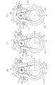
図3(a)に示すように、第2ボルト53が調整ピン挿通孔51a内の下寄り(ラック軸11寄り)に位置するように調整ピン55を回転させると、電動モータ40はラック軸11に近付くように移動する。すると、出力軸収容孔13a内では、出力軸40a及び駆動プーリ36が、共にラック軸11及び従動プーリ34に近付くように移動する。その結果、出力軸40a(駆動プーリ36)の回転中心線P1と、ラック軸11(従動プーリ34)の回転中心線P2との間の距離はD1に調整される。   As shown in FIG. 3A, when the adjustment pin 55 is rotated so that the second bolt 53 is positioned below the adjustment pin insertion hole 51a (closer to the rack shaft 11), the electric motor 40 causes the rack shaft 11 to rotate. Move to get closer. Then, in the output shaft accommodation hole 13a, the output shaft 40a and the drive pulley 36 both move so as to approach the rack shaft 11 and the driven pulley 34. As a result, the distance between the rotation center line P1 of the output shaft 40a (drive pulley 36) and the rotation center line P2 of the rack shaft 11 (driven pulley 34) is adjusted to D1.

図3(b)に示すように、調整ピン55を回転させ、第2ボルト53を調整ピン挿通孔51a内の左寄り(出力軸40a寄り)に位置させると、電動モータ40はラック軸11から若干離れるように移動する。すると、出力軸収容孔13a内では、出力軸40a及び駆動プーリ36が、共にラック軸11及び従動プーリ34から若干離れるように移動する。その結果、出力軸40a(駆動プーリ36)の回転中心線P1と、ラック軸11(従動プーリ34)の回転中心線P2との間の距離はD2に調整される。この距離D2は、上記の距離D1より若干長くなる。   As shown in FIG. 3B, when the adjustment pin 55 is rotated and the second bolt 53 is positioned to the left (close to the output shaft 40a) in the adjustment pin insertion hole 51a, the electric motor 40 is slightly moved from the rack shaft 11. Move away. Then, in the output shaft accommodation hole 13a, both the output shaft 40a and the drive pulley 36 move so as to be slightly separated from the rack shaft 11 and the driven pulley 34. As a result, the distance between the rotation center line P1 of the output shaft 40a (drive pulley 36) and the rotation center line P2 of the rack shaft 11 (driven pulley 34) is adjusted to D2. This distance D2 is slightly longer than the distance D1.

図3(c)に示すように、調整ピン55を回転させ、第2ボルト53を調整ピン挿通孔51a内の上寄り(ラック軸11から離れた位置)に位置させると、電動モータ40はラック軸11から離れるように移動する。すると、出力軸収容孔13a内では、出力軸40a及び駆動プーリ36が、共にラック軸11及び従動プーリ34から離れるように移動する。その結果、出力軸40a(駆動プーリ36)の回転中心線P1と、ラック軸11(従動プーリ34)の回転中心線P2との間の距離はD3に調整される。この距離D3は、距離D1,D2より若干長くなる。   As shown in FIG. 3C, when the adjustment pin 55 is rotated and the second bolt 53 is positioned above the adjustment pin insertion hole 51a (a position away from the rack shaft 11), the electric motor 40 is moved to the rack. Move away from the axis 11. Then, the output shaft 40a and the drive pulley 36 both move away from the rack shaft 11 and the driven pulley 34 in the output shaft accommodation hole 13a. As a result, the distance between the rotation center line P1 of the output shaft 40a (drive pulley 36) and the rotation center line P2 of the rack shaft 11 (driven pulley 34) is adjusted to D3. This distance D3 is slightly longer than the distances D1 and D2.

そして、電動モータ40を移動させて、出力軸40a及び駆動プーリ36と、ラック軸11及び従動プーリ34との距離を調整し、ベルト35の張力が適正な張力に調整されたら、調整ピン55の軸部56を調整ピン挿通孔51a内に挿入するとともに、掛止部57aを掛止凹部51bに掛止させる。その後、第2ボルト53の位置が変動しないようにしながら第1ボルト52及び第2ボルト53をフランジ部43のネジ孔43aに増し締めし、第1及び第2ボルト52,53によりエンドハウジング13に電動モータ40を固定する。   Then, the electric motor 40 is moved to adjust the distance between the output shaft 40a and the drive pulley 36, the rack shaft 11 and the driven pulley 34, and when the tension of the belt 35 is adjusted to an appropriate tension, the adjustment pin 55 The shaft portion 56 is inserted into the adjustment pin insertion hole 51a, and the latching portion 57a is latched to the latching recess 51b. Thereafter, the first bolt 52 and the second bolt 53 are further tightened into the screw hole 43a of the flange portion 43 while preventing the position of the second bolt 53 from fluctuating, and the first housing 52 and the second bolt 52, 53 are attached to the end housing 13. The electric motor 40 is fixed.

次に、ベルト35の張力調整機構の作用について説明する。
図3(a)〜(c)に示すように、ベルト35の張力が調整され、かつ電動モータ40がエンドハウジング13に固定された状態では、ベルト35の張力により、駆動プーリ36(電動モータ40)には、従動プーリ34側への引寄せ力が作用している。よって、電動モータ40をエンドハウジング13に固定する第2ボルト53に対しても、ベルト35の張力に基づく従動プーリ34側への引寄せ力が電動モータ40を介して作用している。このとき、第2ボルト53は調整ピン55に挿通支持され、その調整ピン55は円筒状の軸部56が、円形状の調整ピン挿通孔51aに挿通された状態で調整ピン挿通孔51a内に支持されている。すなわち、第2ボルト53を支持する調整ピン55は、その軸部56の外周側に調整ピン挿通孔51aの内面が位置し、引寄せ力によって引寄せられる側に位置する調整ピン55の周面(端面)は、調整ピン挿通孔51aの内面に当接して常時支持されている。このため、第2ボルト53に引寄せ力が作用していても、その第2ボルト53を支持する調整ピン55が従動プーリ34側へ移動することが防止されることから、第2ボルト53が従動プーリ34側へ移動することが防止される。その結果、駆動プーリ36が従動プーリ34側へ引寄せられることがなく、その引寄せに基づいたベルト35の緩みが防止される。
Next, the operation of the tension adjusting mechanism of the belt 35 will be described.
As shown in FIGS. 3A to 3C, when the tension of the belt 35 is adjusted and the electric motor 40 is fixed to the end housing 13, the driving pulley 36 (the electric motor 40 is driven by the tension of the belt 35. ) Has a pulling force acting on the driven pulley 34 side. Therefore, the pulling force toward the driven pulley 34 based on the tension of the belt 35 also acts on the second bolt 53 that fixes the electric motor 40 to the end housing 13 via the electric motor 40. At this time, the second bolt 53 is inserted and supported by the adjustment pin 55, and the adjustment pin 55 is inserted into the adjustment pin insertion hole 51a in a state where the cylindrical shaft portion 56 is inserted into the circular adjustment pin insertion hole 51a. It is supported. That is, the adjustment pin 55 that supports the second bolt 53 has the inner surface of the adjustment pin insertion hole 51a positioned on the outer peripheral side of the shaft portion 56, and the peripheral surface of the adjustment pin 55 positioned on the side attracted by the pulling force. The (end face) is always supported in contact with the inner surface of the adjustment pin insertion hole 51a. For this reason, even if a pulling force acts on the second bolt 53, the adjustment pin 55 that supports the second bolt 53 is prevented from moving to the driven pulley 34 side. Moving to the driven pulley 34 side is prevented. As a result, the drive pulley 36 is not pulled toward the driven pulley 34, and the belt 35 is prevented from loosening due to the pulling.

上記実施形態によれば、以下のような効果を得ることができる。
(1)ベルト35の張力調整機構において、調整ピン55の軸部56は円形状の調整ピン挿通孔51aに挿通支持されるとともに、調整ピン55の回転に伴い公転する第2ボルト53は、調整ピン55の中心C2から偏心した位置に挿通されている。このため、電動モータ40に固定された第2ボルト53に対し、ベルト35の張力に基づく従動プーリ34側への引き寄せ力が作用しても、第2ボルト53が従動プーリ34側へ移動することが防止され、駆動プーリ36が従動プーリ34側へ引寄せられない結果として、ベルト35の張力が低下することを防止することができる。
According to the above embodiment, the following effects can be obtained.
(1) In the tension adjustment mechanism of the belt 35, the shaft portion 56 of the adjustment pin 55 is inserted and supported in the circular adjustment pin insertion hole 51a, and the second bolt 53 that revolves as the adjustment pin 55 rotates is adjusted. The pin 55 is inserted at a position eccentric from the center C2. For this reason, even if a pulling force toward the driven pulley 34 based on the tension of the belt 35 acts on the second bolt 53 fixed to the electric motor 40, the second bolt 53 moves toward the driven pulley 34. As a result, the tension of the belt 35 can be prevented from decreasing as a result of the drive pulley 36 not being pulled toward the driven pulley 34.

(2)第2ボルト53は、軸部56の中心C2から偏心した位置に挿通されるとともに、調整ピン55は、円形状の調整ピン挿通孔51a内に回転可能に挿通されている。そして、ベルト35の張力調整は、調整ピン55を調整ピン挿通孔51a内で回転させて第2ボルト53を公転させることで行われる。したがって、本実施形態の張力調整機構は、背景技術のように、ベルト張力の調整が、ベルト張力による引寄せ力の作用する方向へ延びる長孔を用いて行われる場合とは異なり、張力調整のために用いられていた長孔そのものが廃止されている。よって、本実施形態では、第2ボルト53に対し従動プーリ34側への引き寄せ力が作用しても、背景技術のように電動モータ40が長孔に沿って移動してしまうことはなく、ベルト35の張力の低下が発生しない。   (2) The second bolt 53 is inserted at a position eccentric from the center C2 of the shaft portion 56, and the adjustment pin 55 is rotatably inserted into the circular adjustment pin insertion hole 51a. The tension of the belt 35 is adjusted by rotating the adjustment pin 55 in the adjustment pin insertion hole 51a and causing the second bolt 53 to revolve. Therefore, unlike the background art, the tension adjusting mechanism of the present embodiment is different from the case where the belt tension is adjusted using a long hole extending in the direction in which the pulling force acts due to the belt tension. The oblong holes used for this purpose have been abolished. Therefore, in this embodiment, even if the pulling force toward the driven pulley 34 acts on the second bolt 53, the electric motor 40 does not move along the long hole as in the background art, and the belt No decrease in the tension of 35 occurs.

(3)調整ピン55において、円筒状の軸部56には、軸部56より大径の頭部57が一体形成されている。この頭部57を工具で把持し、その工具を操作することで、調整ピン55を簡単に回転させることができ、ベルト35の張力調整を簡単に行うことができる。   (3) In the adjustment pin 55, the cylindrical shaft portion 56 is integrally formed with a head portion 57 having a larger diameter than the shaft portion 56. By gripping the head 57 with a tool and operating the tool, the adjustment pin 55 can be easily rotated, and the tension of the belt 35 can be easily adjusted.

(4)調整ピン55の頭部57に掛止部57aを形成し、第2ボルト53をネジ孔43aに増し締めしたとき、掛止部57aを第2モータ取付部51に形成された掛止凹部51bに掛止させた。この掛止により、電動モータ40の振動等による調整ピン55の回転を防止することができ、調整ピン55の回転に伴い第2ボルト53が移動することを防止して、ベルト35の張力の低下を防止することができる。   (4) A latching portion 57a is formed on the head 57 of the adjustment pin 55, and the latching portion 57a is latched on the second motor mounting portion 51 when the second bolt 53 is tightened to the screw hole 43a. The recess 51b is hooked. By this latching, the adjustment pin 55 can be prevented from rotating due to vibrations of the electric motor 40, and the second bolt 53 is prevented from moving along with the rotation of the adjustment pin 55, and the tension of the belt 35 is reduced. Can be prevented.

(5)ベルト35の張力調整機構において、電動モータ40をエンドハウジング13に固定するため、第2ボルト53に加え、第1ボルト52を用いた。この第1ボルト52は、エンドハウジング13の第1モータ取付部50に形成された長孔状のボルト挿通孔50aに挿通される。そして、ベルト35の張力調整の際は、ボルト挿通孔50aの長さ分だけ電動モータ40の移動が許される。ここで、ボルト挿通孔50aの中心線Nは、第1ハウジング14の中央線Cに対して斜めに交差するようになっている。このため、駆動プーリ36に対し、ベルト35の張力に基づく従動プーリ34側への引寄せ力が作用しても、ボルト挿通孔50a内面が第1ボルト52に接触して、電動モータ40の移動を抑制し、ベルト35の張力低下の防止に貢献することができる。   (5) In the tension adjusting mechanism of the belt 35, the first bolt 52 is used in addition to the second bolt 53 in order to fix the electric motor 40 to the end housing 13. The first bolt 52 is inserted into an elongated bolt insertion hole 50 a formed in the first motor mounting portion 50 of the end housing 13. When adjusting the tension of the belt 35, the electric motor 40 is allowed to move by the length of the bolt insertion hole 50a. Here, the center line N of the bolt insertion hole 50 a obliquely intersects the center line C of the first housing 14. For this reason, even if a pulling force toward the driven pulley 34 based on the tension of the belt 35 acts on the drive pulley 36, the inner surface of the bolt insertion hole 50 a contacts the first bolt 52 and the electric motor 40 moves. This can contribute to prevention of a decrease in the tension of the belt 35.

(6)ベルト35の張力調整機構は、第2モータ取付部51に形成した調整ピン挿通孔51a、ボルト状の調整ピン55、及び第2ボルト53からなる。そして、調整ピン挿通孔51aを所定形状に形成し、調整ピン55の所定位置に貫通孔58を形成するといった簡単、かつ安価な構成でベルト35の緩みを防止することができる。   (6) The tension adjustment mechanism of the belt 35 includes an adjustment pin insertion hole 51 a formed in the second motor attachment portion 51, a bolt-shaped adjustment pin 55, and a second bolt 53. The belt 35 can be prevented from loosening with a simple and inexpensive configuration in which the adjustment pin insertion hole 51a is formed in a predetermined shape and the through hole 58 is formed at a predetermined position of the adjustment pin 55.

(7)調整ピン55の軸部56を円筒状に形成し、その軸部56の中心C2から偏心した位置に貫通孔58を形成した。そして、中心C2を回転中心として調整ピン55を回転させ、その回転に伴う第2ボルト53の位置変化によりベルト35の張力を調整する。第2ボルト53の位置は、第2ボルト53の回転軌跡上の任意の位置となるため、微妙な張力調整を可能にする。   (7) The shaft portion 56 of the adjustment pin 55 is formed in a cylindrical shape, and the through hole 58 is formed at a position eccentric from the center C2 of the shaft portion 56. Then, the adjustment pin 55 is rotated with the center C2 as the rotation center, and the tension of the belt 35 is adjusted by the position change of the second bolt 53 accompanying the rotation. Since the position of the second bolt 53 is an arbitrary position on the rotation locus of the second bolt 53, fine tension adjustment is possible.

なお、上記実施形態は以下のように変更してもよい。
○ 実施形態では、ボルト挿通孔50aを長孔状に形成したが、ベルト35の張力調整の際に、調整ピン55の回転に伴う電動モータ40の移動を許すのであれば、ボルト挿通孔50aの形状は長孔状に限定されない。
In addition, you may change the said embodiment as follows.
In the embodiment, the bolt insertion hole 50a is formed in a long hole shape. However, when adjusting the tension of the belt 35, if the movement of the electric motor 40 with the rotation of the adjustment pin 55 is allowed, the bolt insertion hole 50a The shape is not limited to a long hole shape.

○ 実施形態では、掛止部57aを頭部57に2つだけ形成したが、掛止部57aの数は任意に変更してもよい。
○ 実施形態では、掛止部57aが掛止する掛止凹部51bを第2モータ取付部51に形成したが、掛止凹部51bは無くてもよく、この場合は、以下のように変更してもよい。掛止部57aを、第2モータ取付部51(ハウジング12)における調整ピン挿通孔51aの周囲に嵌入させることで、第2モータ取付部51を塑性変形させ、その塑性変形した第2モータ取付部51を被掛止部として掛止部57aを掛止させてもよい。この場合、掛止部57a(調整ピン55)を硬度の高い材料(鉄等)で形成するとともに、被掛止部となる第2モータ取付部51(ハウジング12)を掛止部57aより硬度の低い材料(アルミニウム等)で形成することが好ましい。なお、掛止部を被掛止部に嵌入させたとき、被掛止部が弾性変形するように掛止部及び被掛止部の材料を適宜変更してもよい。
In the embodiment, only two hooks 57a are formed on the head 57, but the number of hooks 57a may be arbitrarily changed.
In the embodiment, the latching recess 51b for latching the latching portion 57a is formed in the second motor mounting portion 51. However, the latching recess 51b may not be provided, and in this case, the following change is made. Also good. By fitting the latching portion 57a around the adjustment pin insertion hole 51a in the second motor attachment portion 51 (housing 12), the second motor attachment portion 51 is plastically deformed, and the plastically deformed second motor attachment portion. The latching portion 57a may be latched with 51 as the latched portion. In this case, the latching portion 57a (adjustment pin 55) is formed of a material having high hardness (iron or the like), and the second motor mounting portion 51 (housing 12) serving as the latched portion is harder than the latching portion 57a. It is preferable to form with a low material (aluminum etc.). In addition, when the latching portion is fitted into the latched portion, the latching portion and the material of the latched portion may be appropriately changed so that the latched portion is elastically deformed.

○ 第2ボルト53の掛止部57a、及び第2モータ取付部51の掛止凹部51bは無くてもよい。
○ 実施形態では、調整ピン55に掛止部57aを突設し、第2モータ取付部51に掛止凹部51bを凹設したが、第2モータ取付部51に掛止部を突設し、調整ピン55の頭部57に被掛止部としての掛止凹部を凹設してもよい。又は、第2モータ取付部51に掛止部を突設するとともに、調整ピン55の頭部57を被掛止部とし、頭部57に掛止部を嵌入させて掛止させてもよい。
O The latching part 57a of the 2nd volt | bolt 53 and the latching recessed part 51b of the 2nd motor attachment part 51 are not necessary.
In the embodiment, the latching portion 57a is projected from the adjustment pin 55, and the latching recess 51b is recessed from the second motor mounting portion 51. However, the latching portion is projected from the second motor mounting portion 51, A hooking recess as a hooked portion may be provided in the head 57 of the adjustment pin 55. Alternatively, a latching portion may be provided on the second motor mounting portion 51, and the head 57 of the adjustment pin 55 may be a latched portion, and the latching portion may be fitted into the head 57 to be latched.

○ 実施形態では、調整ピン55の頭部57を工具で操作して調整ピン55を回転させたが、頭部57は無くてもよく、頭部57の代わりに、軸部56から突設された操作部を操作して調整ピン55を回転させてもよい。   In the embodiment, the adjustment pin 55 is rotated by operating the head 57 of the adjustment pin 55 with a tool. However, the head 57 may be omitted, and is projected from the shaft portion 56 instead of the head 57. The adjusting pin 55 may be rotated by operating the operating unit.

○ 実施形態では、モータとして電動モータ40に具体化したが、エンジン等の外部駆動源で駆動されるモータであってもよい。
○ 実施形態では、固定部材として第2ボルト53に具体化したが、固定部材は、電動モータ40をエンドハウジング13に固定できるのであれば、電動モータ40に形成された固定穴に圧入される圧入ピンであってもよく、その他の固定形式を有する固定部材であってもよい。
In the embodiment, the electric motor 40 is embodied as a motor, but a motor driven by an external drive source such as an engine may be used.
In the embodiment, the second bolt 53 is embodied as a fixing member. However, the fixing member is press-fitted into a fixing hole formed in the electric motor 40 as long as the electric motor 40 can be fixed to the end housing 13. It may be a pin, or may be a fixing member having another fixing type.

○ 実施形態では、固定部材として第2ボルト53を用いたが、第2ボルト53を用いてベルト35の張力を調整し、増し締めした後、さらに、第1ボルト52に加え別のボルトを用いて電動モータ40をエンドハウジング13に固定してもよい。   In the embodiment, the second bolt 53 is used as the fixing member. However, after the tension of the belt 35 is adjusted using the second bolt 53 and tightened, another bolt is used in addition to the first bolt 52. The electric motor 40 may be fixed to the end housing 13.

○ 実施形態では、出力軸40aに連結された駆動プーリ36と、ラック軸11に連結された従動プーリ34とにベルト35を掛け渡して動力伝達可能にしたが、動力伝達機構はこれに限らず、適宜変更してもよい。例えば、出力軸40aに連結したスプロケットと、ラック軸11に連結されたスプロケットとをチェーンで連結して動力伝達可能にしてもよい。   In the embodiment, the belt 35 is stretched over the drive pulley 36 connected to the output shaft 40a and the driven pulley 34 connected to the rack shaft 11 to enable power transmission. However, the power transmission mechanism is not limited to this. , May be changed as appropriate. For example, the sprocket connected to the output shaft 40a and the sprocket connected to the rack shaft 11 may be connected by a chain so that power can be transmitted.

○ 実施形態では、調整ピン挿通孔51aを円形状に形成したが、調整ピン挿通孔51aは、その内側で調整ピン55の軸部56が回転可能であり、かつ従動プーリ34側への引寄せ力が作用しても、調整ピン55の引寄せ側の周面が当接し調整ピン55の移動を規制できるのであれば、ほぼ円形に近い楕円や多角形状であってもよい。   In the embodiment, the adjustment pin insertion hole 51a is formed in a circular shape. However, the adjustment pin insertion hole 51a can rotate the shaft portion 56 of the adjustment pin 55 on the inner side, and draw toward the driven pulley 34 side. Even if a force is applied, as long as the peripheral surface of the adjustment pin 55 on the drawing side abuts and the movement of the adjustment pin 55 can be restricted, an ellipse or polygonal shape that is almost circular may be used.

○ 実施形態では、調整ピン55の軸部56を円筒状に形成したが、軸部56は調整ピン挿通孔51a内で回転可能であれば、ほぼ円筒に近い筒状や多角筒状であってもよい。   In the embodiment, the shaft portion 56 of the adjustment pin 55 is formed in a cylindrical shape. However, if the shaft portion 56 is rotatable in the adjustment pin insertion hole 51a, the shaft portion 56 has a substantially cylindrical or polygonal tube shape. Also good.

C…中央線、C2…軸部の中心、L1,L2…中心軸、N…中心線、10…EPS(電動パワーステアリング装置)、11…ラック軸、12…ハウジング、13a…出力軸収容孔、14a…ラック軸収容孔、35…ベルト、40…モータとしての電動モータ、40a…出力軸、50a…挿通孔としてのボルト挿通孔、51a…調整ピン挿通孔、51b…被掛止部としての掛止凹部、52…別の固定部材としての第1ボルト、53…固定部材としての第2ボルト、55…調整ピン、56…軸部、57…頭部、57a…掛止部、58…貫通孔。   C ... center line, C2 ... shaft center, L1, L2 ... center axis, N ... center line, 10 ... EPS (electric power steering device), 11 ... rack shaft, 12 ... housing, 13a ... output shaft receiving hole, 14a ... Rack shaft accommodation hole, 35 ... Belt, 40 ... Electric motor as motor, 40a ... Output shaft, 50a ... Bolt insertion hole as insertion hole, 51a ... Adjustment pin insertion hole, 51b ... Hook as hooked portion Stop recess 52... First bolt as another fixing member 53. Second bolt as a fixing member 55. Adjustment pin 56. Shaft portion 57. Head portion 57 a. .

Claims (5)

ラック軸を収容するハウジングには、該ハウジングを貫通した固定部材がモータに固定されることにより前記モータが固定され、前記モータの駆動により発生する動力を該モータの出力軸からベルトを介して前記ラック軸に伝達し、前記動力を、ステアリング操作を補助するためのアシスト力として前記ラック軸に付与する電動パワーステアリング装置において、
前記ベルトの張力調整機構として、
円形状の調整ピン挿通孔を前記ハウジングに有するとともに、
前記調整ピン挿通孔に挿通される調整ピンを有しており、
前記調整ピンに、前記調整ピン挿通孔に回転可能に挿通支持される軸部が形成されるとともに、前記軸部の中心から偏心した位置に、前記固定部材を前記モータに固定するために該固定部材が挿通される貫通孔が形成されていることを特徴とする電動パワーステアリング装置。
In the housing that houses the rack shaft, the motor is fixed by fixing a fixing member penetrating the housing to the motor, and the power generated by driving the motor is transmitted from the motor output shaft through the belt. In the electric power steering device that transmits the power to the rack shaft and applies the power to the rack shaft as an assist force for assisting a steering operation.
As the tension adjustment mechanism of the belt,
While having a circular adjustment pin insertion hole in the housing,
It has an adjustment pin inserted through the adjustment pin insertion hole,
A shaft portion that is rotatably inserted and supported in the adjustment pin insertion hole is formed in the adjustment pin, and the fixing member is fixed to the motor at a position eccentric from the center of the shaft portion. An electric power steering apparatus, wherein a through-hole through which a member is inserted is formed.
前記軸部の軸方向一端には、該軸部より大径をなす頭部が形成されている請求項1に記載の電動パワーステアリング装置。   The electric power steering apparatus according to claim 1, wherein a head portion having a larger diameter than the shaft portion is formed at one axial end of the shaft portion. 前記頭部及び前記ハウジングのいずれか一方には掛止部が形成されるとともに、他方には前記固定部材の前記モータへの固定に伴い前記掛止部が掛止する被掛止部が形成されている請求項2に記載の電動パワーステアリング装置。   A latching portion is formed on one of the head and the housing, and a latched portion on which the latching portion is latched when the fixing member is fixed to the motor is formed on the other. The electric power steering apparatus according to claim 2. 前記ハウジングには、前記固定部材とは別の固定部材が挿通される挿通孔が形成されるとともに、該挿通孔は長孔状に形成されている請求項1〜請求項3のうちいずれか一項に記載の電動パワーステアリング装置。 The housing is formed with an insertion hole through which a fixing member different from the fixing member is inserted, and the insertion hole is formed in a long hole shape. The electric power steering device according to the item. 前記ハウジングには前記出力軸が挿通される出力軸収容孔が形成されるとともに、前記ラック軸が挿通されるラック軸収容孔が形成され、前記出力軸収容孔とラック軸収容孔の中心軸同士を結ぶ直線を中央線とすると、前記挿通孔は、該挿通孔の中心線が前記中央線に対し交差するように形成されている請求項4に記載の電動パワーステアリング装置。 The housing is formed with an output shaft receiving hole through which the output shaft is inserted, and a rack shaft receiving hole through which the rack shaft is inserted, and the output shaft receiving hole and the central axis of the rack shaft receiving hole are The electric power steering apparatus according to claim 4, wherein the insertion hole is formed such that a center line of the insertion hole intersects the center line, where a straight line connecting the two is a center line.
JP2010263811A 2010-11-26 2010-11-26 Electric power steering device Expired - Fee Related JP5644426B2 (en)

Priority Applications (1)

Application Number Priority Date Filing Date Title
JP2010263811A JP5644426B2 (en) 2010-11-26 2010-11-26 Electric power steering device

Applications Claiming Priority (1)

Application Number Priority Date Filing Date Title
JP2010263811A JP5644426B2 (en) 2010-11-26 2010-11-26 Electric power steering device

Publications (2)

Publication Number Publication Date
JP2012111418A true JP2012111418A (en) 2012-06-14
JP5644426B2 JP5644426B2 (en) 2014-12-24

Family

ID=46496099

Family Applications (1)

Application Number Title Priority Date Filing Date
JP2010263811A Expired - Fee Related JP5644426B2 (en) 2010-11-26 2010-11-26 Electric power steering device

Country Status (1)

Country Link
JP (1) JP5644426B2 (en)

Cited By (5)

* Cited by examiner, † Cited by third party
Publication number Priority date Publication date Assignee Title
KR20160094038A (en) * 2015-01-30 2016-08-09 주식회사 만도 Rack Assist Type Electric Power Steering System
KR20160094015A (en) * 2015-01-30 2016-08-09 주식회사 만도 Electric Power Steering Apparatus
KR20160149704A (en) * 2015-06-19 2016-12-28 현대모비스 주식회사 Power steering apparatus
WO2023035150A1 (en) * 2021-09-08 2023-03-16 华为技术有限公司 Transmission apparatus, method for adjusting transmission apparatus, steering system, and vehicle
JP7339930B2 (en) 2020-08-19 2023-09-06 本田技研工業株式会社 steering gear

Citations (6)

* Cited by examiner, † Cited by third party
Publication number Priority date Publication date Assignee Title
JPS4949358U (en) * 1972-08-07 1974-04-30
JPS5726623U (en) * 1980-07-22 1982-02-12
JP2005029145A (en) * 2003-05-06 2005-02-03 Nsk Ltd Belt speed reducer for electric power steering device, and electric power steering device
JP2005329912A (en) * 2004-05-21 2005-12-02 Showa Corp Electric power steering device
JP2005343434A (en) * 2004-06-07 2005-12-15 Showa Corp Electric power steering device
JP2007153300A (en) * 2005-12-01 2007-06-21 Mando Corp Motor drive type steering device

Patent Citations (6)

* Cited by examiner, † Cited by third party
Publication number Priority date Publication date Assignee Title
JPS4949358U (en) * 1972-08-07 1974-04-30
JPS5726623U (en) * 1980-07-22 1982-02-12
JP2005029145A (en) * 2003-05-06 2005-02-03 Nsk Ltd Belt speed reducer for electric power steering device, and electric power steering device
JP2005329912A (en) * 2004-05-21 2005-12-02 Showa Corp Electric power steering device
JP2005343434A (en) * 2004-06-07 2005-12-15 Showa Corp Electric power steering device
JP2007153300A (en) * 2005-12-01 2007-06-21 Mando Corp Motor drive type steering device

Cited By (8)

* Cited by examiner, † Cited by third party
Publication number Priority date Publication date Assignee Title
KR20160094038A (en) * 2015-01-30 2016-08-09 주식회사 만도 Rack Assist Type Electric Power Steering System
KR20160094015A (en) * 2015-01-30 2016-08-09 주식회사 만도 Electric Power Steering Apparatus
KR102222578B1 (en) 2015-01-30 2021-03-05 주식회사 만도 Electric Power Steering Apparatus
KR102242944B1 (en) 2015-01-30 2021-04-21 주식회사 만도 Rack Assist Type Electric Power Steering System
KR20160149704A (en) * 2015-06-19 2016-12-28 현대모비스 주식회사 Power steering apparatus
KR102216192B1 (en) 2015-06-19 2021-02-16 현대모비스 주식회사 Power steering apparatus
JP7339930B2 (en) 2020-08-19 2023-09-06 本田技研工業株式会社 steering gear
WO2023035150A1 (en) * 2021-09-08 2023-03-16 华为技术有限公司 Transmission apparatus, method for adjusting transmission apparatus, steering system, and vehicle

Also Published As

Publication number Publication date
JP5644426B2 (en) 2014-12-24

Similar Documents

Publication Publication Date Title
JP5644426B2 (en) Electric power steering device
EP1886899A1 (en) Electric power steering apparatus equipped with a mechanism for adjusting the tension of a transmission belt
US8944208B2 (en) Power steering apparatus
JP2016055830A (en) Steering device
JP2015047882A (en) Steering device
JP2015186973A (en) Power steering device and assembly method of the same
JP2006027577A (en) Electric power steering device
JP2015174615A (en) Steering gear
JP2005022634A (en) Electric power steering device
JP5883693B2 (en) Reduction device for electric power steering device
JP2010241258A (en) Electric power steering device
JP6135179B2 (en) Steering device
JP2006232049A (en) Electric steering device
JP2011247353A (en) Yoke for universal joint and universal joint having the same
JP6379414B2 (en) Power steering device
JP2013184682A (en) Electric power steering device
JP2005329912A (en) Electric power steering device
CN112719866A (en) Bolt screwing connecting device and method for screwing connecting bolt in rotor journal disc cavity
EP2921373A1 (en) Steering device
JP2013024299A (en) Belt tension adjusting device and electric power steering device
JP5336311B2 (en) Member coupling structure, eccentric oscillating gear device, method of forming member coupling structure, and manufacturing method of eccentric oscillating gear device
JP2005324708A (en) Electric power steering device
JP2011183941A (en) Electric power steering device
JP2005212654A (en) Motor power steering device
JP2014061754A (en) Electric power steering device

Legal Events

Date Code Title Description
A621 Written request for application examination

Free format text: JAPANESE INTERMEDIATE CODE: A621

Effective date: 20131021

A977 Report on retrieval

Free format text: JAPANESE INTERMEDIATE CODE: A971007

Effective date: 20140306

A131 Notification of reasons for refusal

Free format text: JAPANESE INTERMEDIATE CODE: A131

Effective date: 20140408

A521 Written amendment

Free format text: JAPANESE INTERMEDIATE CODE: A523

Effective date: 20140519

TRDD Decision of grant or rejection written
A01 Written decision to grant a patent or to grant a registration (utility model)

Free format text: JAPANESE INTERMEDIATE CODE: A01

Effective date: 20141007

A61 First payment of annual fees (during grant procedure)

Free format text: JAPANESE INTERMEDIATE CODE: A61

Effective date: 20141020

R150 Certificate of patent or registration of utility model

Ref document number: 5644426

Country of ref document: JP

Free format text: JAPANESE INTERMEDIATE CODE: R150

LAPS Cancellation because of no payment of annual fees