JP2012108355A - Noise control device for electric equipment - Google Patents
Noise control device for electric equipment Download PDFInfo
- Publication number
- JP2012108355A JP2012108355A JP2010257729A JP2010257729A JP2012108355A JP 2012108355 A JP2012108355 A JP 2012108355A JP 2010257729 A JP2010257729 A JP 2010257729A JP 2010257729 A JP2010257729 A JP 2010257729A JP 2012108355 A JP2012108355 A JP 2012108355A
- Authority
- JP
- Japan
- Prior art keywords
- plate portion
- wall plate
- housing
- electric device
- wall
- Prior art date
- Legal status (The legal status is an assumption and is not a legal conclusion. Google has not performed a legal analysis and makes no representation as to the accuracy of the status listed.)
- Granted
Links
Images


Abstract
Description
本発明は、例えば、コンデンサ、変圧器やリアクトル等の電気機器において、その電気機器が発する振動等に起因する騒音を低減する電気機器用防音装置に関する。 The present invention relates to a soundproofing device for an electric device that reduces noise caused by vibration generated by the electric device in an electric device such as a capacitor, a transformer, and a reactor.
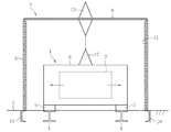
例えば、電気機器の一つであるコンデンサにおいては、交流電圧印加によって素子内部振動が発生し、この振動に起因して騒音が発生する。この種の電気機器1は、図4に示すように、電気機器1が発する騒音を低減させるための防音装置3と共に現地のコンクリート基礎2上に設置される(例えば、特許文献1参照)。この電気機器1および防音装置3の設置作業は以下の手順でもって行われる。
For example, in a capacitor, which is one of electric devices, internal vibration of an element is generated by applying an alternating voltage, and noise is generated due to the vibration. As shown in FIG. 4, this type of electric device 1 is installed on a
まず、現地のコンクリート基礎2に電気機器用ベース4を埋設し、その電気機器用ベース4上に防振部材5を介して電気機器1を設置する。このように、コンクリート基礎2と電気機器1との間に防振部材5を介在させることにより、電気機器1が発する振動がコンクリート基礎2に伝わらないようにしている。この電気機器1がコンデンサの場合、ハウジング6に収容された構成要素7から発せられる振動の伝搬方向が図中の矢印で示すように横方向となっていることから、電気機器1の四方側面と上面を覆うように防音装置3を設置する。
First, the electric equipment base 4 is embedded in the
この防音装置3は、電気機器1の四方側面を囲撓する壁板部8と、その壁板部8の上方開口部を閉塞する天板部9とで構成されている。コンクリート基礎2に防音装置用ベース10を埋設し、壁板部8および天板部9を組み立てその壁板部8を防音装置用ベース10上に設置して溶接等により固定している。
The
なお、壁板部8の内面には吸音材11が取り付けられている。また、電気機器1のハウジング6の上面に設けられた内部碍子12と、防音装置3の天板部9に設けられた外部碍子13とを電気的に接続することにより、電気機器1の入出力端子を外部に導出した構造としている。
A
ところで、前述した従来の電気機器用防音装置3では、電気機器用ベース4および防音装置用ベース10をコンクリート基礎2に埋め込む作業、防音装置3の壁板部8を防音装置用ベース10に溶接する作業などで非常に手間がかかり、現地での組み立て工数などの多大なコストがかかるという問題があった。
By the way, in the conventional electrical
また、従来の防音装置3は、電気機器1のハウジング全体を取り囲む構造を採用していることから、電気機器1のハウジング6の内部碍子12と防音装置3の天板部9の外部碍子13とを電気的に接続しなければならず、構成部材の数も多くなるという問題もあった。
In addition, since the
そこで、本発明は前述した問題点に鑑みて提案されたもので、その目的とするところは、従来と同等の防音性能を維持しつつ、現地での設置作業を簡易にしてコスト低減を図り得るコンパクトな電気機器用防音装置を提供することにある。 Therefore, the present invention has been proposed in view of the above-described problems, and the object of the present invention is to reduce the cost by simplifying the installation work at the site while maintaining the soundproof performance equivalent to the conventional one. The object is to provide a compact soundproofing device for electrical equipment.
前述の目的を達成するための技術的手段として、本発明は、基礎上に載置されるベースが取付けられた底板部と、その底板部の周縁部から起立するように一体的に設けられた壁板部とを備え、電気機器のハウジングを壁板部の内側に収容すると共に防振部材を介して底板部上に固定し、電気機器のハウジングの開口部を蓋板部で閉塞すると共に、その蓋板部を壁板部の開口部に覆い被せたことを特徴とする。 As a technical means for achieving the above-described object, the present invention is provided integrally with a base plate portion to which a base placed on a foundation is attached and an upright portion from the peripheral edge portion of the base plate portion. A wall plate portion, and the housing of the electric device is accommodated inside the wall plate portion and fixed on the bottom plate portion via the vibration isolation member, and the opening of the electric device housing is closed with the lid plate portion, The lid plate portion is covered with the opening of the wall plate portion.
本発明では、電気機器のハウジングの開口部を蓋板部で閉塞すると共に、その蓋板部を壁板部の開口部に覆い被せたことにより、この蓋板部は、従来の防音装置の天板部と電気機器のハウジングの一部とに兼用された機能を発揮する。これにより、防音装置のコンパクト化が図れる。 In the present invention, the opening portion of the housing of the electric device is closed with the lid plate portion, and the lid plate portion is covered with the opening portion of the wall plate portion. It functions as a plate and a part of the housing of the electric device. As a result, the soundproofing device can be made compact.
また、電気機器のハウジングを壁板部の内側に収容すると共に防振部材を介して底板部上に固定し、その底板部にベースが取り付けられた構造としていることから、電気機器と防音装置とのユニット化が可能となり、電気機器を組み込んだ防音装置を基礎上に設置するだけで済むため、従来と同等の防音性能を維持しつつ、現地での設置作業の簡易化が図れる。 In addition, since the housing of the electric device is housed inside the wall plate portion and fixed on the bottom plate portion via a vibration isolating member, and the base is attached to the bottom plate portion, the electric device, the soundproofing device, The unit can be unitized, and it is only necessary to install a soundproofing device incorporating electric equipment on the foundation, so that the installation work at the site can be simplified while maintaining the soundproofing performance equivalent to the conventional one.
本発明における蓋板部は、その周縁部を屈曲させて壁板部の外周面に沿って延在するフランジ部を有し、そのフランジ部の内周面と壁板部の外周面との間に隙間を設けると共に、その壁板部の外周面のフランジ部対向部位に防振部材を配設した構造が望ましい。 The lid plate portion in the present invention has a flange portion that bends its peripheral portion and extends along the outer peripheral surface of the wall plate portion, and is between the inner peripheral surface of the flange portion and the outer peripheral surface of the wall plate portion. A structure in which a vibration isolating member is provided in a portion facing the flange portion on the outer peripheral surface of the wall plate portion is desirable.
このように、蓋板部の周縁部を屈曲させて壁板部の外周面に沿って延在するフランジ部を設ければ、電気機器を屋外に設置する場合であっても、防音装置の外部から雨水が侵入しにくい構造とすることができる。また、フランジ部の内周面と壁板部の外周面との間に隙間を設ければ、蓋板部を組み付けるに際し、壁板部に対する位置決め誤差を吸収することができる。さらに、その壁板部の外周面のフランジ部対向部位に防振部材を配設すれば、フランジ部が壁板部に当接した状態となっても、蓋板部から伝わってくる電気機器の振動を防振部材で吸収し、壁板部および底板部を介して基礎に伝わらないようにすることができる。 In this way, if the flange portion extending along the outer peripheral surface of the wall plate portion is provided by bending the peripheral portion of the lid plate portion, the outside of the soundproofing device can be provided even when the electric device is installed outdoors. Therefore, it is possible to make a structure in which rainwater hardly enters. Further, if a gap is provided between the inner peripheral surface of the flange portion and the outer peripheral surface of the wall plate portion, positioning errors with respect to the wall plate portion can be absorbed when the cover plate portion is assembled. Furthermore, if a vibration isolating member is disposed at the flange portion facing portion of the outer peripheral surface of the wall plate portion, even if the flange portion is in contact with the wall plate portion, the electrical equipment transmitted from the cover plate portion The vibration can be absorbed by the vibration isolating member so that it is not transmitted to the foundation through the wall plate portion and the bottom plate portion.
本発明における電気機器は、ハウジングの内周に空間を介して区画壁部を備え、その区画壁部の内部に構成要素を収容した構造が望ましい。 The electric device according to the present invention preferably has a structure in which a partition wall portion is provided on the inner periphery of the housing via a space, and components are accommodated inside the partition wall portion.
このようにすれば、構成要素を区画壁部とハウジングの二重構造で収容することができ、構成要素で発する振動に起因する騒音は、区画壁部、空間およびハウジングを経て電気機器の外部に出ることになり、防音性能がより一層向上する。 In this way, the component can be accommodated in a double structure of the partition wall portion and the housing, and noise caused by vibrations generated by the component is transmitted to the outside of the electric device through the partition wall portion, the space, and the housing. The soundproof performance will be further improved.
本発明によれば、電気機器のハウジングの開口部を蓋板部で閉塞すると共に、その蓋板部を壁板部の開口部に覆い被せたことにより、この蓋板部が、従来の防音装置の天板部と電気機器のハウジングの一部とに兼用された機能を持つことから、防音装置のコンパクト化が図れる。また、電気機器のハウジングを壁板部の内側に収容すると共に防振部材を介して底板部上に固定し、その底板部にベースが取り付けられた構造としていることから、電気機器と防音装置とのユニット化が可能となり、電気機器を組み込んだ防音装置を基礎上に設置するだけで済むため、現地での設置作業の簡易化が図れる。その結果、従来と同等の防音性能を維持しつつ、現地での設置作業を簡易にしてコスト低減を図り得るコンパクトな電気機器用防音装置を提供できる。 According to the present invention, the opening portion of the housing of the electric device is closed with the lid plate portion, and the lid plate portion is covered with the opening portion of the wall plate portion. The soundproofing device can be made compact because it has a function shared by both the top plate portion and the housing of the electric device. In addition, since the housing of the electric device is housed inside the wall plate portion and fixed on the bottom plate portion via a vibration isolating member, and the base is attached to the bottom plate portion, the electric device, the soundproofing device, Can be unitized, and it is only necessary to install a soundproofing device incorporating electric equipment on the foundation, so that installation work at the site can be simplified. As a result, it is possible to provide a compact soundproofing device for electrical equipment that can reduce the cost by simplifying the installation work at the site while maintaining the soundproofing performance equivalent to the conventional one.
本発明に係る電気機器用防音装置の実施形態を以下に詳述する。なお、以下の実施形態では、電気機器としてコンデンサを例示するが、変圧器やリアクトル等の他の電気機器、つまり、振動等に起因する騒音を低減させる必要がある電気機器に適用可能である。この電気機器用防音装置は、通常、屋外に設置される。 An embodiment of a soundproofing device for an electrical apparatus according to the present invention will be described in detail below. In the following embodiments, a capacitor is illustrated as an electrical device, but the present invention can be applied to other electrical devices such as a transformer and a reactor, that is, an electrical device that needs to reduce noise caused by vibration or the like. This electrical equipment soundproofing device is usually installed outdoors.
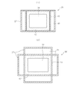
この実施形態における電気機器用防音装置21は、図1に示すように、コンクリート基礎22上に載置されるH型鋼などのベース23が取付けられた平面矩形状の底板部24と、その底板部24の周縁部から起立するように一体的に設けられた壁板部25と、その壁板部25の内側に収容された電気機器26のハウジング27の上方開口部を閉塞すると共に壁板部25の上方開口部に覆い被せられた蓋板部28とを備えている。
As shown in FIG. 1, the
なお、電気機器26の周囲四方を囲撓する壁板部25の内面には吸音材29が取り付けられている。また、壁板部25の外面には、運搬時や設置時に防音装置全体を吊り下げるための吊手30が設けられている。
A
蓋板部28は、電気機器26のハウジング27の上方開口部に対してその上方開口部を隙間なく密封するように閉塞し、図2に示すように、壁板部25の上方開口部に対してその上方開口部との間に隙間31を介在させるようにして覆い被せられている。また、蓋板部28は、その周縁部を屈曲させて壁板部25の外周面に沿って延在するフランジ部32を有する。そのフランジ部32の内周面と壁板部25の外周面との間に隙間33を設けると共に、その壁板部25の外周面のフランジ部対向部位に防振ゴム等の防振部材34を全周に亘って配設している。
The
なお、この蓋板部28には、電気機器26の入出力端子を外部に導出するための碍子35が設けられている。また、蓋板部28の上面には、運搬時や組付時に蓋板部28を吊り下げるための吊手36が設けられている。
The
壁板部25の内側に収容された電気機器26は、そのハウジング27の底部と底板部24との間に配設された防振ゴム等の防振部材37を介して底板部24上にボルト38により締め付け固定される。このように、電気機器26と底板部24との間に防振部材37を介在させることにより、電気機器26が発する振動が底板部24を介してコンクリート基礎22に伝わらないようにして騒音の発生を抑制している。なお、ボルト38についても防振ゴム等の防振部材43を介して取り付けられている。
The
この電気機器26がコンデンサの場合、ハウジング27に収容された構成要素39から発せられる振動の伝搬方向が図中の矢印で示すように横方向となっていることから、電気機器26の四方側面と上面を覆うように底板部24に一体に設けられた壁板部25と蓋板部28とで防音装置21を構成している。
In the case where the
また、電気機器26は、図3(A)(B)に示すように、ハウジング27の内周に空間40を介して区画壁部41を備え、その区画壁部41の内部に絶縁油42を充填した状態で構成要素39(コンデンサ要素)を収容した構造を具備している。なお、電気機器26は、同図(B)に示すように区画壁部41の四方に独立した空間40を設けた構造以外に、区画壁部41の周囲に連続した環状空間を設けた構造であってもよい。
As shown in FIGS. 3A and 3B, the
以上の構成からなる電気機器用防音装置21では、電気機器26のハウジング27の上方開口部を蓋板部28で閉塞すると共に、その蓋板部28を壁板部25の上方開口部に覆い被せたことにより、この蓋板部28が、従来の防音装置3(図4参照)の天板部9と電気機器1のハウジング6の一部(上部)とに兼用された機能を発揮する。これにより、防音装置21のコンパクト化が図れる。また、電気機器26に蓋板部28を直接的に取り付け、その蓋板部28に碍子35を設けた構造であることから、従来の防音装置3における内部碍子12と外部碍子13とを電気的に接続する構造(図4参照)が省略できる点で、部品点数の削減も図れる。
In the electrical
このように、蓋板部28が従来の防音装置3(図4参照)の天板部9と電気機器1の一部とに兼用され、壁板部25の内側に収容した電気機器26を底板部24上に固定し、その底板部24にベース23が取り付けられた構造としている。このことから、電気機器26と防音装置21とのユニット化が可能となり、工場で電気機器26を組み込んだ防音装置21を現場に搬入してコンクリート基礎22上に設置するだけで済むため、従来と同等の防音性能を維持しつつ、現地での設置作業の簡易化が図れる。
As described above, the
また、蓋板部28が、図2に示すように、壁板部25の上方開口部に対してその上方開口部との間に隙間31を介在させた構造となっていることにより、電気機器26から発せられた振動が蓋板部28から壁板部25および底板部24を介してコンクリート基礎22に伝わらないようにして騒音の発生を抑制している。また、蓋板部28の周縁部にフランジ部32を設けていることから、電気機器26を屋外に設置する場合であっても、防音装置21の外部から雨水が侵入しにくい構造となっている。
Further, as shown in FIG. 2, the
ここで、フランジ部32の内周面と壁板部25の外周面との間に隙間33を設けているので、蓋板部28を組み付けるに際し、壁板部25に対して水平方向での位置決め誤差を吸収することができる。さらに、その壁板部25の外周面のフランジ部対向部位に防振部材34を全周に亘って配設していることから、フランジ部32が壁板部25に当接した状態となっても、蓋板部28から伝わってくる電気機器26の振動を防振部材34で吸収し、壁板部25および底板部24を介してコンクリート基礎22に伝わらないようにして騒音の発生を抑制している。
Here, since the
さらに、電気機器26は、図3(A)(B)に示すように、絶縁油42を充填した状態で構成要素39(コンデンサ要素)を収容した区画壁部41と、その区画壁部41との間に空間40を介在させたハウジング27との二重構造を具備していることから、構成要素39で発せられた振動に起因する騒音は、区画壁部41、空間40およびハウジング27を経て電気機器26の外部に出ることになり、電気機器26の外部に出る騒音をより一層抑制することが容易になっている。
Further, as shown in FIGS. 3A and 3B, the
本発明は前述した実施形態に何ら限定されるものではなく、本発明の要旨を逸脱しない範囲内において、さらに種々なる形態で実施し得ることは勿論のことであり、本発明の範囲は、特許請求の範囲によって示され、さらに特許請求の範囲に記載の均等の意味、および範囲内のすべての変更を含む。 The present invention is not limited to the above-described embodiments, and can of course be implemented in various forms without departing from the gist of the present invention. It includes the equivalent meanings recited in the claims and the equivalents recited in the claims, and all modifications within the scope.
22 基礎(コンクリート基礎)
23 ベース
24 底板部
25 壁板部
26 電気機器
27 ハウジング
28 蓋板部
32 フランジ部
33 隙間
34 防振部材
37 防振部材
39 構成要素
40 空間
41 区画壁部
22 Foundation (concrete foundation)
23
Claims (3)
Priority Applications (2)
| Application Number | Priority Date | Filing Date | Title |
|---|---|---|---|
| JP2010257729A JP6001819B2 (en) | 2010-11-18 | 2010-11-18 | Soundproofing equipment for electrical equipment |
| CN2011204714962U CN202332267U (en) | 2010-11-18 | 2011-11-18 | Sound arrester for electronic device |
Applications Claiming Priority (1)
| Application Number | Priority Date | Filing Date | Title |
|---|---|---|---|
| JP2010257729A JP6001819B2 (en) | 2010-11-18 | 2010-11-18 | Soundproofing equipment for electrical equipment |
Publications (2)
| Publication Number | Publication Date |
|---|---|
| JP2012108355A true JP2012108355A (en) | 2012-06-07 |
| JP6001819B2 JP6001819B2 (en) | 2016-10-05 |
Family
ID=46444239
Family Applications (1)
| Application Number | Title | Priority Date | Filing Date |
|---|---|---|---|
| JP2010257729A Active JP6001819B2 (en) | 2010-11-18 | 2010-11-18 | Soundproofing equipment for electrical equipment |
Country Status (2)
| Country | Link |
|---|---|
| JP (1) | JP6001819B2 (en) |
| CN (1) | CN202332267U (en) |
Cited By (4)
| Publication number | Priority date | Publication date | Assignee | Title |
|---|---|---|---|---|
| CN105374552A (en) * | 2015-12-17 | 2016-03-02 | 日新电机(无锡)有限公司 | Capacitor with soundproof cover |
| KR102026890B1 (en) * | 2019-05-10 | 2019-09-30 | 우진전기 주식회사 | Amorphous transformer with core frame and dual bottom layer outer housing for reduction of noise and vibration |
| KR102077127B1 (en) * | 2019-12-02 | 2020-02-14 | 주식회사 신성이엔티 | Noise reduction type transformer |
| WO2022157825A1 (en) * | 2021-01-19 | 2022-07-28 | 三菱電機株式会社 | Elevator control device |
Families Citing this family (1)
| Publication number | Priority date | Publication date | Assignee | Title |
|---|---|---|---|---|
| CN107068142A (en) * | 2017-05-16 | 2017-08-18 | 太仓市友达电气技术有限公司 | A kind of sound arrester for electronic device |
Citations (4)
| Publication number | Priority date | Publication date | Assignee | Title |
|---|---|---|---|---|
| JPS5180875U (en) * | 1974-12-23 | 1976-06-28 | ||
| JPH06186983A (en) * | 1992-12-21 | 1994-07-08 | Mitsubishi Electric Corp | Soundproof plate and soundproof device of static induction apparatus formed by using the plate |
| JPH072849U (en) * | 1993-05-31 | 1995-01-17 | 東陶機器株式会社 | Soundproof structure of functional parts in bathtub water circulation system |
| JP2003308073A (en) * | 2002-04-16 | 2003-10-31 | Nissin Electric Co Ltd | Soundproof device for electric apparatus |
-
2010
- 2010-11-18 JP JP2010257729A patent/JP6001819B2/en active Active
-
2011
- 2011-11-18 CN CN2011204714962U patent/CN202332267U/en not_active Expired - Lifetime
Patent Citations (4)
| Publication number | Priority date | Publication date | Assignee | Title |
|---|---|---|---|---|
| JPS5180875U (en) * | 1974-12-23 | 1976-06-28 | ||
| JPH06186983A (en) * | 1992-12-21 | 1994-07-08 | Mitsubishi Electric Corp | Soundproof plate and soundproof device of static induction apparatus formed by using the plate |
| JPH072849U (en) * | 1993-05-31 | 1995-01-17 | 東陶機器株式会社 | Soundproof structure of functional parts in bathtub water circulation system |
| JP2003308073A (en) * | 2002-04-16 | 2003-10-31 | Nissin Electric Co Ltd | Soundproof device for electric apparatus |
Cited By (5)
| Publication number | Priority date | Publication date | Assignee | Title |
|---|---|---|---|---|
| CN105374552A (en) * | 2015-12-17 | 2016-03-02 | 日新电机(无锡)有限公司 | Capacitor with soundproof cover |
| KR102026890B1 (en) * | 2019-05-10 | 2019-09-30 | 우진전기 주식회사 | Amorphous transformer with core frame and dual bottom layer outer housing for reduction of noise and vibration |
| KR102077127B1 (en) * | 2019-12-02 | 2020-02-14 | 주식회사 신성이엔티 | Noise reduction type transformer |
| WO2022157825A1 (en) * | 2021-01-19 | 2022-07-28 | 三菱電機株式会社 | Elevator control device |
| JP7400997B2 (en) | 2021-01-19 | 2023-12-19 | 三菱電機株式会社 | elevator control device |
Also Published As
| Publication number | Publication date |
|---|---|
| CN202332267U (en) | 2012-07-11 |
| JP6001819B2 (en) | 2016-10-05 |
Similar Documents
| Publication | Publication Date | Title |
|---|---|---|
| JP6001819B2 (en) | Soundproofing equipment for electrical equipment | |
| JP6597242B2 (en) | Vibration control structure of static induction equipment | |
| KR100910840B1 (en) | Rotary electric machine | |
| JP5498233B2 (en) | Static induction machine | |
| CN101641751A (en) | Power transformer/reactor | |
| KR20170000481A (en) | Earthquake-proof apparatus for distributing board | |
| JP6423688B2 (en) | Static induction machine | |
| KR20200068829A (en) | Encapsulated type dynamic vibration absorber | |
| JP6417189B2 (en) | Static induction machine | |
| JP2020188093A (en) | Transformer | |
| JP2010051135A (en) | Rotary electric machine | |
| KR200476729Y1 (en) | Motor fixing structure | |
| JP2970998B2 (en) | Stationary guidance equipment | |
| US9824814B2 (en) | Acoustic panels for transformers | |
| JP5828313B2 (en) | Electrical equipment case | |
| KR20190086734A (en) | Anti-vibration and anti-vibration engines | |
| JP2008301541A (en) | Terminal box of motor | |
| JP2015070180A (en) | Stationary induction electric device | |
| JP6173237B2 (en) | Stationary induction equipment | |
| JPH1116750A (en) | Stationary induction electric apparatus | |
| JP2017204546A (en) | Stationary induction machine | |
| JPH118135A (en) | Soundproof stationary induction electrical equipment | |
| JP2005337043A (en) | Noise reduction method of power generating device | |
| JP2003308073A (en) | Soundproof device for electric apparatus | |
| CN115966385A (en) | Oil tank composite sound insulation cover and oil-immersed transformer with same |
Legal Events
| Date | Code | Title | Description |
|---|---|---|---|
| A621 | Written request for application examination |
Free format text: JAPANESE INTERMEDIATE CODE: A621 Effective date: 20131114 |
|
| A977 | Report on retrieval |
Free format text: JAPANESE INTERMEDIATE CODE: A971007 Effective date: 20140905 |
|
| A131 | Notification of reasons for refusal |
Free format text: JAPANESE INTERMEDIATE CODE: A131 Effective date: 20140930 |
|
| A521 | Request for written amendment filed |
Free format text: JAPANESE INTERMEDIATE CODE: A523 Effective date: 20141128 |
|
| A02 | Decision of refusal |
Free format text: JAPANESE INTERMEDIATE CODE: A02 Effective date: 20150616 |
|
| A521 | Request for written amendment filed |
Free format text: JAPANESE INTERMEDIATE CODE: A523 Effective date: 20150909 |
|
| A521 | Request for written amendment filed |
Free format text: JAPANESE INTERMEDIATE CODE: A821 Effective date: 20150910 |
|
| A911 | Transfer to examiner for re-examination before appeal (zenchi) |
Free format text: JAPANESE INTERMEDIATE CODE: A911 Effective date: 20151008 |
|
| A912 | Re-examination (zenchi) completed and case transferred to appeal board |
Free format text: JAPANESE INTERMEDIATE CODE: A912 Effective date: 20151228 |
|
| A61 | First payment of annual fees (during grant procedure) |
Free format text: JAPANESE INTERMEDIATE CODE: A61 Effective date: 20160902 |
|
| R150 | Certificate of patent or registration of utility model |
Ref document number: 6001819 Country of ref document: JP Free format text: JAPANESE INTERMEDIATE CODE: R150 |
|
| R250 | Receipt of annual fees |
Free format text: JAPANESE INTERMEDIATE CODE: R250 |
|
| R250 | Receipt of annual fees |
Free format text: JAPANESE INTERMEDIATE CODE: R250 |
|
| R250 | Receipt of annual fees |
Free format text: JAPANESE INTERMEDIATE CODE: R250 |
|
| R250 | Receipt of annual fees |
Free format text: JAPANESE INTERMEDIATE CODE: R250 |
|
| R250 | Receipt of annual fees |
Free format text: JAPANESE INTERMEDIATE CODE: R250 |