JP2012108270A - Multi-display device - Google Patents

Multi-display device Download PDF

Info

Publication number
JP2012108270A
JP2012108270A JP2010256349A JP2010256349A JP2012108270A JP 2012108270 A JP2012108270 A JP 2012108270A JP 2010256349 A JP2010256349 A JP 2010256349A JP 2010256349 A JP2010256349 A JP 2010256349A JP 2012108270 A JP2012108270 A JP 2012108270A
Authority
JP
Japan
Prior art keywords
display
reflecting
reflective
frame
display device
Prior art date
Legal status (The legal status is an assumption and is not a legal conclusion. Google has not performed a legal analysis and makes no representation as to the accuracy of the status listed.)
Granted
Application number
JP2010256349A
Other languages
Japanese (ja)
Other versions
JP5722004B2 (en
Inventor
Tomokazu Miyazawa
友和 宮澤
Daisuke Saeki
太祐 佐伯
Kenji Tanaka
健二 田中
Current Assignee (The listed assignees may be inaccurate. Google has not performed a legal analysis and makes no representation or warranty as to the accuracy of the list.)
Sharp Corp
Original Assignee
Sharp Corp
Priority date (The priority date is an assumption and is not a legal conclusion. Google has not performed a legal analysis and makes no representation as to the accuracy of the date listed.)
Filing date
Publication date
Application filed by Sharp Corp filed Critical Sharp Corp
Priority to JP2010256349A priority Critical patent/JP5722004B2/en
Priority to PCT/JP2011/069931 priority patent/WO2012035988A1/en
Publication of JP2012108270A publication Critical patent/JP2012108270A/en
Application granted granted Critical
Publication of JP5722004B2 publication Critical patent/JP5722004B2/en
Active legal-status Critical Current
Anticipated expiration legal-status Critical

Links

Images

Abstract

PROBLEM TO BE SOLVED: To provide a multi-display device with which the deterioration of display quality due to exposure of non-display parts such as frames is prevented without any thermal accumulation with a simple structure and at low costs.SOLUTION: At each of frames 5 adjacent to each other of a plurality of liquid crystal panels 2 which are arranged in a matrix in a flat manner, have the frames 5 as non-display parts on their peripheries and have display regions formed for displaying images at positions closer to the inside than the frames 5, there is provided a reflection member 8 having reflection surfaces 6, 7 at which emission light from the display regions closer to the inside of the surface than the respective frames 5 is reflected. The reflection surfaces 6, 7 include bending portions 6a, 7a.

Description

本発明は、複数の表示パネルを隣接して配置し、1つの大画面を構成するマルチディスプレイ装置に関する。   The present invention relates to a multi-display device in which a plurality of display panels are arranged adjacent to each other to form one large screen.

近年、インフォメーションディスプレイおよび業務用ディスプレイとして、たとえば4台あるいは9台の表示パネルを縦横に隣接して配置し、1つの大きな画面を構成し、1台のパーソナルコンピュータから、DVI(Digital Visual Interface)やアナログRGB(Red Green Blue)映像信号、HDMI(High-Definition Multimedia Interface)などのインターフェイスを経由して接続された各表示パネルへ、1つの画像を分割した画面信号を送ることによって、各表示パネルに画像が個別に表示され、画面全体として一連の画像を表示することができるように構成されている。   In recent years, as information displays and business displays, for example, four or nine display panels are arranged adjacent to each other in the vertical and horizontal directions to form one large screen, and from one personal computer, DVI (Digital Visual Interface) or By sending a screen signal obtained by dividing one image to each display panel connected via an interface such as an analog RGB (Red Green Blue) video signal or HDMI (High-Definition Multimedia Interface), Images are displayed individually, and a series of images can be displayed as a whole screen.

このようなマルチディスプレイ装置は、複数の表示パネルによっていわゆるマルチ画面とも称される大形の画面を容易に構築することができるが、各表示パネルの額縁上には画像を表示することができないため、隣接する各表示パネル間の目地または継目などに対応する領域に、表示画面上に線が格子状に入ったように見え、表示品位が低下してしまうという問題がある。   Such a multi-display device can easily construct a large screen, which is also referred to as a so-called multi-screen, by a plurality of display panels, but cannot display an image on the frame of each display panel. In the area corresponding to the joints or joints between the adjacent display panels, lines appear on the display screen as if they were in a grid pattern, and the display quality is degraded.

このような問題を解決するための従来技術は、たとえば特許文献1に提案されている。特許文献1に記載される従来技術では、1つの画像を4画面を使用して大きく映し出しているときに、画像を格子状に区切って目障りとなるという問題を解決するために、互いに独立な駆動系を介して映像信号によって駆動される画像表示する複数の画像表示器の表示画面を2次元的に配列して大形画面を形成した多画面表示装置において、表示画面の隣接するもの同士の境界領域に補助表示器を配列したマルチディスプレイ装置が提案されている。   A conventional technique for solving such a problem is proposed in Patent Document 1, for example. In the prior art described in Patent Document 1, in order to solve the problem that when one image is projected greatly using four screens, the image is divided into a lattice shape, the drive is independent from each other. In a multi-screen display device in which a large screen is formed by two-dimensionally arranging display screens of a plurality of image display devices that display an image driven by a video signal through a system, a boundary between adjacent display screens A multi-display device in which auxiliary displays are arranged in the area has been proposed.

この従来技術では、額縁に設けた補助表示装置に発光ダイオードを用い、非表示領域を挟む画面近傍の平均輝度によって駆動するように構成されている。しかしながら、額縁上で液晶カラー表示素子、発光ダイオード、エレクトロルミネセンスなどの電子部品を制御するため、製造コストが高額となり、かつ消費電力が大きくなるという課題がある。   In this prior art, a light emitting diode is used for an auxiliary display device provided in a frame, and the display is driven by an average luminance in the vicinity of a screen across a non-display area. However, since electronic components such as a liquid crystal color display element, a light emitting diode, and electroluminescence are controlled on the frame, there are problems that the manufacturing cost is high and the power consumption is large.

また、前述のような電子部品を用いず光学的に解決する従来技術は、たとえば特許文献2,3に開示されている。これらの従来技術には、画面上に配置した凸レンズおよび凹レンズを用いて、画面表示光を屈折させ、額縁上まで拡張して表示する構成が提案されている。特許文献2に記載される従来技術では、複数のプラズマディスプレイパネル(Plasma
Display Panel、略称PDP)を縦横に並べて、各PDPの表示画面を繋ぎ合わせて1つの大画面として表示するために、各PDPの前面には、凸レンズ群の行列からなる第1のマルチレンズおよび第2のマルチレンズを配置して、PDPの表示画面に表示する表示画像の正立像を形成し、第2のマルチレンズの前面には、さらに、凹レンズを配置して、上記の正立像をPDP等の前面に配置した透過型スクリーン上に拡大して投影し、複数のPDPに表示した画像を連続した1つの画像として表示することができるマルチディスプレイ装置が提案されている。
Moreover, the prior art which solves optically without using the above electronic components is disclosed by patent document 2, 3, for example. In these prior arts, a configuration has been proposed in which screen display light is refracted by using a convex lens and a concave lens arranged on the screen, and is extended and displayed on the frame. In the prior art described in Patent Document 2, a plurality of plasma display panels (Plasma
Display panels (abbreviated as PDPs) are arranged vertically and horizontally, and the display screens of the respective PDPs are connected and displayed as one large screen. 2 is arranged to form an erect image of the display image to be displayed on the display screen of the PDP, and a concave lens is further arranged on the front surface of the second multi lens so that the above erect image is displayed on the PDP or the like. There has been proposed a multi-display device capable of displaying an image displayed on a plurality of PDPs as a single continuous image by enlarging and projecting the image on a transmission screen arranged in front of the display.

また特許文献3に記載される従来技術では、画像が投射されるスクリーンが前面に装着されるスクリーンブロックを多段に積み上げて大形の画面を形成してなるマルチ投射型スクリーンにおいて、マルチ画面で生じる目地を目立たなくするため、前記画像が投射される各平行平板スクリーンブロックの光出射側に周辺が凸レンズ構造で中央部が平板であるレンズ状透明スクリーンを装着したマルチディスプレイ装置が提案されている。   Further, in the prior art described in Patent Document 3, a multi-projection screen is formed on a multi-projection screen in which a large screen is formed by stacking screen blocks on which a screen on which an image is projected is mounted on the front surface. In order to make the joint inconspicuous, a multi-display device is proposed in which a lens-shaped transparent screen having a convex lens structure at the periphery and a flat plate at the center is provided on the light exit side of each parallel flat screen block on which the image is projected.

しかしながら、これらの特許文献2,3の各従来技術を実施するためには、画面を覆う大きさの凹レンズや、画面と同サイズのアクリル板の側端部をレンズ状に加工する必要があり、大形のディスプレイ装置になるほど高額な部品が必要となる上、表示画面とレンズとの間に熱が蓄積するという問題がある。   However, in order to implement each of the prior arts of these Patent Documents 2 and 3, it is necessary to process a concave lens having a size covering the screen and a side end of an acrylic plate having the same size as the screen into a lens shape, The larger the display device, the more expensive parts are required, and heat is accumulated between the display screen and the lens.

さらに他の従来技術として、たとえば特許文献4〜6には、光ファイバの束を用いて、画面表示を額縁上に偏移させ、非表示部としての額縁を見えなくすることが提案されている。特許文献4に記載される従来技術では、ディスプレイの外周に非表示部(目地)を有するマルチディスプレイ装置において、前記ディスプレイの発光面上に光軸が傾斜した光ファイバプレートを備えたマルチディスプレイ装置が提案されている。   As another conventional technique, for example, Patent Documents 4 to 6 propose using a bundle of optical fibers to shift the screen display onto the frame so as to make the frame as a non-display portion invisible. . In the prior art described in Patent Document 4, in a multi-display device having a non-display portion (joint) on the outer periphery of the display, a multi-display device including an optical fiber plate having an optical axis inclined on the light emitting surface of the display is disclosed. Proposed.

また特許文献5に記載される従来技術では、表示部とこの表示部を囲む額縁とを備えた平板状の表示ユニットの前面に、偏位手段を設け、この偏位手段によって表示ユニットに表示される分割画面を2次元方向に偏位させて分割画面を一体化させることによって、額縁による境界線のない大画面を形成することができるマルチディスプレイ装置が提案されている。   In the prior art described in Patent Document 5, a displacement unit is provided on the front surface of a flat display unit having a display unit and a frame surrounding the display unit, and is displayed on the display unit by the displacement unit. There has been proposed a multi-display device capable of forming a large screen without a border line by a frame by integrating the divided screens by shifting the divided screens in a two-dimensional direction.

さらに特許文献6に記載される従来技術では、複数の投影機と並列して投影部を設け、これと同様の導光体を投影機と同様に並べてスクリーン部を構成し、導光体の画像光入力端面に、対応する投影機から画像光を投影可能とし、該導光体の反対側の端面である画像光出力端面を、前記画像表示面よりも中心側に偏倚させて、画面内に額縁が生じることのない統一画像表示面を形成するマルチディスプレイ装置が提案されている。この従来技術の導光体は、光ファイバを束ねてなり、画像光入力端面から画像光出力端面の間で光路が、統一画像表示面の中心側寄りに設けられる。   Furthermore, in the prior art described in Patent Document 6, a projection unit is provided in parallel with a plurality of projectors, and a light guide similar to this is arranged in the same manner as the projector to form a screen unit. The image light can be projected from the corresponding projector onto the light input end surface, and the image light output end surface, which is the end surface on the opposite side of the light guide, is biased toward the center side with respect to the image display surface. There has been proposed a multi-display device that forms a unified image display surface in which no frame is generated. This prior art light guide is formed by bundling optical fibers, and an optical path between the image light input end surface and the image light output end surface is provided closer to the center side of the unified image display surface.

これらの特許文献4〜6に記載される各従来技術では、該従来技術に係るマルチディスプレイ装置を実現するために、画素数に相当する本数の光ファイバの束が必要となり、製造コストが高額になってしまうという問題がある。   In each of the prior arts described in Patent Documents 4 to 6, a bundle of optical fibers corresponding to the number of pixels is required to realize the multi-display device according to the prior art, and the manufacturing cost is high. There is a problem of becoming.

特開平3−38982号公報JP-A-3-38982 特開平10−222095号公報Japanese Patent Laid-Open No. 10-2222095 特開2000−180964号公報JP 2000-180964 A 特開平9−37194号公報JP-A-9-37194 特開平10−39780号公報JP 10-39780 A 特開2004−177632号公報JP 2004-177632 A

本発明の目的は、簡単な構成でかつ安価な製造コストで、熱の蓄積を生じず、額縁などの非表示部に起因する表示品位の低下を防止することができるマルチディスプレイ装置を提供することである。   An object of the present invention is to provide a multi-display device that has a simple configuration and low manufacturing cost, does not cause heat accumulation, and can prevent deterioration in display quality due to a non-display portion such as a frame. It is.

第1の本発明に係るマルチディスプレイ装置は、画像を表示する表示領域と、該表示領域を外囲する非表示部とを有し、互いに隣接して設けられる複数の表示パネルと、
前記非表示部に設けられ、前記表示領域からの出射光を反射する反射面を有する反射部材であって、前記反射面に外方に凸に湾曲した湾曲部分が設けられる反射部材とを含むことを特徴とするマルチディスプレイ装置である。
The multi-display device according to the first aspect of the present invention includes a display area for displaying an image, and a plurality of display panels provided adjacent to each other, each having a non-display portion surrounding the display area,
A reflective member that is provided in the non-display portion and has a reflective surface that reflects light emitted from the display region, the reflective member having a curved portion curved outwardly on the reflective surface. Is a multi-display device.

また、本発明のマルチディスプレイ装置において、前記反射部材は、前記非表示部から突出する2つの斜面を有する三角柱状の長尺材から成り、各斜面に前記反射面が形成される反射部を有し、該反射部の反射面の前記非表示部側の部分に、前記湾曲部分が形成されることを特徴とする。   In the multi-display device of the present invention, the reflecting member is formed of a long triangular prism-shaped material having two inclined surfaces protruding from the non-display portion, and has a reflecting portion on which the reflecting surface is formed on each inclined surface. And the said curved part is formed in the part by the side of the said non-display part of the reflective surface of this reflection part, It is characterized by the above-mentioned.

さらに、本発明のマルチディスプレイ装置において、前記反射部材は、前記湾曲部分を含む2つの反射面が形成される反射部と、該反射部に連なり、前記各表示パネルの互いに隣接する各非表示部によって挟持される挟持部とを有することを特徴とする。   Furthermore, in the multi-display device according to the present invention, the reflecting member includes a reflecting portion on which two reflecting surfaces including the curved portion are formed, and the non-display portions adjacent to each other of the display panels that are connected to the reflecting portion. And a sandwiching portion sandwiched between the two.

第2の本発明に係るマルチディスプレイ装置は、画像を表示する表示領域と、該表示領域を外囲する非表示部とを有し、互いに隣接して設けられる複数の表示パネルと、
前記非表示部に設けられ、前記表示領域からの出射光を反射する反射面を有する反射部材であって、前記反射面が、前記非表示部を覆い、かつ、該非表示部に対して傾斜した1つの平面状の反射面から成ることを特徴とするマルチディスプレイ装置である。
A multi-display device according to a second aspect of the present invention includes a display area that displays an image, and a plurality of display panels that are provided adjacent to each other, each having a non-display portion that surrounds the display area,
A reflective member provided in the non-display portion and having a reflective surface for reflecting light emitted from the display region, the reflective surface covering the non-display portion and inclined with respect to the non-display portion A multi-display device comprising a single planar reflecting surface.

また、本発明のマルチディスプレイ装置において、前記反射部材は、前記平面状の反射面が形成される反射部と、該反射部に連なり、前記各表示パネルの互いに隣接する各非表示部によって挟持される挟持部とを有することを特徴とする。   In the multi-display device of the present invention, the reflection member is sandwiched between a reflection portion on which the planar reflection surface is formed and non-display portions adjacent to each other of the display panels that are connected to the reflection portion. And a holding portion.

さらに、本発明のマルチディスプレイ装置において、前記反射部は、前記挟持部に対して、反射部材の長手方向に沿った軸線まわりに回動可能に連結され、前記反射面の前記非表示部に対する傾斜角度が調整可能に構成されることを特徴とする。   Furthermore, in the multi-display device according to the present invention, the reflecting portion is connected to the sandwiching portion so as to be rotatable about an axis along the longitudinal direction of the reflecting member, and the reflecting surface is inclined with respect to the non-display portion. The angle is configured to be adjustable.

第3の本発明に係るマルチディスプレイ装置は、画像を表示する表示領域と、該表示領域を外囲する非表示部とを有し、互いに隣接して設けられる複数の表示パネルと、
前記非表示部に設けられ、前記表示領域からの出射光を反射する反射面を有する反射部材であって、前記反射面が、粗面化された粗面化処理部を含むことを特徴とするマルチディスプレイ装置である。
A multi-display device according to a third aspect of the present invention includes a display area that displays an image, and a plurality of display panels that are provided adjacent to each other, each having a non-display portion that surrounds the display area,
A reflection member provided in the non-display portion and having a reflection surface that reflects light emitted from the display region, wherein the reflection surface includes a roughening treatment portion that is roughened. It is a multi-display device.

また、本発明のマルチディスプレイ装置において、前記反射部材は、前記非表示部から突出する2つの斜面を有し、かつ断面形状が三角形の柱状部材から成り、各斜面に前記反射面が形成されることを特徴とする。   In the multi-display device of the present invention, the reflection member has two inclined surfaces protruding from the non-display portion, and is formed of a columnar member having a triangular cross section, and the reflection surface is formed on each inclined surface. It is characterized by that.

さらに、本発明のマルチディスプレイ装置において、前記反射面の粗面化処理部は、前記非表示部から突出方向に向かって粗度が大きくなるように形成されることを特徴とする。   Furthermore, in the multi-display device of the present invention, the roughening processing portion of the reflecting surface is formed so that the roughness increases from the non-display portion toward the protruding direction.

さらに、本発明のマルチディスプレイ装置において、前記反射部材は、前記2つの反射面が形成される反射部と、該反射部に連なり、前記各表示パネルの互いに隣接する各非表示部によって挟持される挟持部とを有することを特徴とする。   Furthermore, in the multi-display device of the present invention, the reflecting member is sandwiched between a reflecting portion where the two reflecting surfaces are formed and non-display portions adjacent to each other of the display panels that are connected to the reflecting portion. And a holding portion.

第1の本発明に係るマルチディスプレイ装置によれば、平面状に並んで配置される複数の表示パネルの各非表示部に、表示領域からの出射光を反射する反射面を有する反射部材が設けられるので、各表示パネルを組立ててマルチスクリーンを構築した状態での表示画面に、非表示部が線状に露呈することを防止し、表示品位を向上することができる。しかも、反射面が湾曲部分を含むから、この湾曲部分によって、平面状の反射面に比べて非表示部により近い部位の表示領域からの出射光を反射させることができる。したがって、表示領域からの出射光による画像と、反射面からの反射光による画像との違和感をより少なくすることができる。さらに、隣接する表示領域からの出射光による画像の連続的視認性も改良される。また、反射部材は反射面を有する機械的部品によって実現され、前記従来技術のような電子部品あるいは光ファイバなどの光学部品を用いないため、安価な製造コストで非表示部が露呈しない低消費電力で、かつ蓄熱も伴わないマルチディスプレイ装置を実現することができる。   According to the multi-display device of the first aspect of the present invention, each non-display portion of the plurality of display panels arranged side by side is provided with a reflecting member having a reflecting surface that reflects the emitted light from the display area. Therefore, it is possible to prevent the non-display portion from being exposed in a linear shape on the display screen in a state in which each display panel is assembled to construct a multi-screen, and display quality can be improved. In addition, since the reflection surface includes a curved portion, it is possible to reflect the emitted light from the display region closer to the non-display portion than the planar reflection surface. Therefore, it is possible to further reduce the uncomfortable feeling between the image generated by the light emitted from the display area and the image generated by the reflected light from the reflecting surface. Furthermore, the continuous visibility of the image by the emitted light from the adjacent display area is also improved. In addition, since the reflecting member is realized by a mechanical part having a reflecting surface and does not use an electronic part or an optical part such as an optical fiber as in the prior art, low power consumption that does not expose a non-display part at a low manufacturing cost. In addition, it is possible to realize a multi-display device that does not accompany heat storage.

また本発明によれば、反射部材は断面形状が山形の柱状部材の各非表示部から突出する2つの斜面に反射面が形成されるので、各非表示部の両側の表示領域からの出射光を各反射面によってそれぞれ反射して、各非表示部が線状に露見されること防止し、各非表示部を介して隣接する各表示領域の表示画像を、外見上、実質的に連続した画像として視認することができる。しかも、反射面の前記非表示部側の部分が前記湾曲部分とされ、かつ、該湾曲部分より前記突出方向側の部分が断面三角形を成すよう形成されているので、湾曲部分が表示領域により近く位置することになる。これによって、表示領域からの画像と反射面からの画像との違和感をより少なくすることができるとともに、隣接する各表示領域における表示画像の連続視認性がより向上する。   Further, according to the present invention, the reflecting member is formed on the two inclined surfaces protruding from each non-display portion of the columnar member having a mountain-shaped cross section, so that the light emitted from the display regions on both sides of each non-display portion Are reflected by each reflecting surface to prevent each non-display portion from being exposed linearly, and the display image of each display area adjacent to each other through each non-display portion is substantially continuous in appearance. It can be visually recognized as an image. In addition, since the portion on the non-display portion side of the reflecting surface is the curved portion, and the portion on the protruding direction side from the curved portion is formed in a cross-sectional triangle, the curved portion is closer to the display area. Will be located. As a result, the discomfort between the image from the display area and the image from the reflecting surface can be reduced, and the continuous visibility of the display image in each adjacent display area is further improved.

さらに本発明によれば、前記反射部材は、前記湾曲部分を含む2つの反射面が形成される反射部と、該反射部に連なり、前記各表示パネルの互いに隣接する各側部によって挟持される挟持部とを有するので、反射部材を各表示パネルの各非表示部に正確に位置決めされた状態で容易かつ確実に設けることができる。   Further, according to the present invention, the reflecting member is sandwiched between a reflecting portion on which two reflecting surfaces including the curved portion are formed, and side portions adjacent to each other of the display panels that are connected to the reflecting portion. Therefore, the reflecting member can be easily and reliably provided in a state where the reflecting member is accurately positioned on each non-display portion of each display panel.

第2の本発明に係るマルチディスプレイ装置によれば、第1の本発明と同様に、平面状に並んで配置される複数の表示パネルの各非表示部に、表示領域からの出射光を反射する反射面を有する反射部材が設けられるので、各表示パネルを組立ててマルチスクリーンを構築した状態での表示画面に、非表示部が線状に露呈することを防止し、表示品位を向上することができる。しかも、本発明では、1個の平面状の反射面が非表示部に対して斜めに配されるから、反射部材を三角柱状体で構成する場合のように、反射面の中央に頂上部による線が視認されることがない。   According to the multi-display device of the second aspect of the present invention, similarly to the first aspect of the present invention, the emitted light from the display area is reflected on each non-display portion of the plurality of display panels arranged in a plane. Since a reflective member having a reflective surface is provided, it is possible to prevent the non-display portion from being exposed linearly on the display screen in a state in which each display panel is assembled to construct a multi-screen, thereby improving display quality. Can do. Moreover, in the present invention, since one planar reflection surface is arranged obliquely with respect to the non-display portion, the top of the reflection surface is formed at the center of the reflection surface as in the case where the reflection member is formed of a triangular prism. The line is not visible.

また本発明によれば、前記反射部材は、前記平面状の反射面が形成される反射部と、該反射部に連なり、前記各表示パネルの互いに隣接する各側部によって挟持される挟持部とを有するので、反射部材を各表示パネルの各非表示部に正確に位置決めされた状態で容易かつ確実に設けることができる。   According to the invention, the reflecting member includes a reflecting portion on which the planar reflecting surface is formed, and a sandwiching portion that is connected to the reflecting portion and is sandwiched between adjacent side portions of the display panels. Therefore, it is possible to easily and reliably provide the reflecting member in a state where the reflecting member is accurately positioned in each non-display portion of each display panel.

さらに本発明によれば、前記反射部は、前記挟持部に対して、反射部材の長手方向に沿った軸線回りに回動可能に連結され、前記反射面の前記非表示部に対する傾斜角度が調整可能とされているので、反射部材の設置位置に応じて反射面の最適傾斜角度を設定することができる。特に、マルチスクリーンの設置場所毎の看者の立つ位置を想定し、反射部材の設置位置に応じて反射面の最適傾斜角度を設定すれば、全体としての表示品位が一層向上する。   Further, according to the present invention, the reflecting portion is connected to the sandwiching portion so as to be rotatable around an axis along the longitudinal direction of the reflecting member, and an inclination angle of the reflecting surface with respect to the non-display portion is adjusted. Since it is possible, the optimal inclination angle of the reflecting surface can be set according to the installation position of the reflecting member. In particular, assuming the position where the observer stands for each installation place of the multi-screen, and setting the optimum inclination angle of the reflection surface according to the installation position of the reflection member, the overall display quality is further improved.

第3の本発明に係るマルチディスプレイ装置によれば、第1あるいは第2の本発明と同様に、平面状に並んで配置される複数の表示パネルの各非表示部に、表示領域からの出射光を反射する反射面を有する反射部材が設けられるので、各表示パネルを組立ててマルチスクリーンを構築した状態での表示画面に、非表示部が線状に露呈することを防止し、表示品位を向上することができる。しかも、本発明では、前記反射部材の反射面が、粗面化処理部を含むから、表示領域からの出射光は粗面化処理部で乱反射し、この乱反射光による映像はぼやけて視認される。したがって、隣接する表示領域において非表示部をまたがる斜線のような映像がある場合に、反射映像が左右あるいは上下に反転することによって、かえって見づらくなるようなことを防止するのに有効である。   According to the multi-display device of the third aspect of the present invention, as in the case of the first or second aspect of the present invention, the non-display portion of the plurality of display panels arranged in a plane is provided on the non-display portion from the display area. Since a reflective member having a reflective surface that reflects incident light is provided, the display screen in the state where each display panel is assembled to construct a multi-screen is prevented, and the non-display portion is prevented from being exposed linearly, and the display quality is improved. Can be improved. Moreover, in the present invention, since the reflecting surface of the reflecting member includes the roughening processing unit, the light emitted from the display area is irregularly reflected by the roughening processing unit, and the image of the irregularly reflected light is visually recognized. . Therefore, in the case where there is an image such as a slanting line across the non-display portion in the adjacent display region, it is effective to prevent the reflected image from becoming difficult to see by flipping left and right or up and down.

また本発明によれば、前記反射部材は、断面形状が三角形の柱状部材から成り、該柱状部材の前記非表示部から突出する2つの斜面が前記反射面とされているので、各非表示部の両側の表示領域からの出射光を各反射面によってそれぞれ反射して、各非表示部が線状に露見されること防止し、各非表示部を介して隣接する各表示領域の表示画像を、外見上、実質的に連続した画像として視認することができる。   According to the invention, the reflecting member is formed of a columnar member having a triangular cross-sectional shape, and the two inclined surfaces protruding from the non-displaying portion of the columnar member are the reflecting surfaces. The light emitted from the display areas on both sides of the screen is reflected by the respective reflecting surfaces to prevent the non-display parts from being exposed in a linear manner, and the display images of the adjacent display areas via the non-display parts are displayed. In appearance, it can be visually recognized as a substantially continuous image.

さらに本発明によれば、前記反射面の粗面化処理部は、前記非表示部から突出方向に向け、粗面化度合いが大きくなるよう形成されているので、非表示部から離れた位置の表示領域からの出射光がより乱反射し易く、これによって、前記反射映像の左右あるいは上下反転による視認性の不具合をより有効に防止することができる。   Further, according to the present invention, the roughening processing portion of the reflecting surface is formed so that the degree of roughening increases in the protruding direction from the non-display portion. The outgoing light from the display area is more likely to be diffusely reflected, and thereby, it is possible to more effectively prevent the visibility defect due to left-right or upside-down inversion of the reflected image.

さらに本発明によれば、前記反射部材は、前記2つの反射面が形成される反射部と、該反射部に連なり、前記各表示パネルの互いに隣接する各側部によって挟持される挟持部とを有するので、反射部材を各表示パネルの各非表示部に正確に位置決めされた状態で容易かつ確実に設けることができる。   Further, according to the present invention, the reflecting member includes a reflecting portion on which the two reflecting surfaces are formed, and a sandwiching portion that is connected to the reflecting portion and is sandwiched between the adjacent side portions of the display panels. Therefore, the reflecting member can be easily and reliably provided in a state where the reflecting member is accurately positioned in each non-display portion of each display panel.

第1の本発明に係るマルチディスプレイ装置1の一実施形態を示す断面図である。It is sectional drawing which shows one Embodiment of the multi-display apparatus 1 which concerns on 1st this invention. 図1のマルチディスプレイ装置1の一部分を簡素化して示す斜視図である。It is a perspective view which simplifies and shows a part of the multi-display apparatus 1 of FIG. 図2の切断面線III−IIIから見た断面図である。It is sectional drawing seen from the cut surface line III-III of FIG. 本実施形態における反射部材8を示す一部の拡大斜視図である。It is a partial expansion perspective view which shows the reflection member 8 in this embodiment. 反射部材8が隣接する2つの額縁5に設置された状態を示す一部の斜視図である。It is a partial perspective view which shows the state in which the reflection member 8 was installed in the two adjacent frame 5. 反射部材8aがマルチディスプレイ装置1の外側の額縁5に設置された状態を示す一部の斜視図である。FIG. 6 is a partial perspective view showing a state in which the reflecting member 8a is installed on the outer frame 5 of the multi-display device 1. 液晶パネル2からの出射光の反射パターンを示す図であり、図7(1)は本実施形態の反射部材8による反射パターンを示す図であり、図7(2)は比較例として反射部材の反射面が平面である場合の反射パターンを示す図である。It is a figure which shows the reflective pattern of the emitted light from the liquid crystal panel 2, FIG.7 (1) is a figure which shows the reflective pattern by the reflective member 8 of this embodiment, FIG.7 (2) is a reflection member as a comparative example. It is a figure which shows a reflective pattern in case a reflective surface is a plane. マルチディスプレイ装置1の表示状態を示す正面図であり、図8(1)は額縁5に反射部材8が設けられていないときの画面の表示状態を示し、図8(2)は額縁5に反射部材8を設けたときの画面の表示状態を示す図である。FIG. 8A is a front view showing a display state of the multi-display device 1, FIG. 8A shows a display state of the screen when the reflecting member 8 is not provided on the frame 5, and FIG. It is a figure which shows the display state of a screen when the member 8 is provided. 本発明の他の実施形態の反射部材8bを具備するマルチディスプレイ装置1aを示す一部の断面図である。It is a partial cross section figure which shows the multi-display apparatus 1a which comprises the reflection member 8b of other embodiment of this invention. 本発明のさらに他の実施形態の反射部材8cを具備するマルチディスプレイ装置1bを示す一部の断面図である。It is a partial cross section figure which shows the multi-display apparatus 1b which comprises the reflection member 8c of further another embodiment of this invention. 本発明のさらに他の実施形態の反射部材8dを具備するマルチディスプレイ装置1cを示す一部の断面図である。It is a partial cross section figure which shows the multi-display apparatus 1c which comprises the reflection member 8d of further another embodiment of this invention. 本発明のマルチディスプレイ装置1の全体斜視図と、同マルチディスプレイ装置1における反射部材8の交差部Aの一部を拡大して示す斜視図である。FIG. 2 is an overall perspective view of the multi-display device 1 of the present invention, and an enlarged perspective view showing a part of an intersection A of a reflecting member 8 in the multi-display device 1. 図12の交差部Aの拡大平面図である。FIG. 13 is an enlarged plan view of an intersection A in FIG. 12. 図13に示す反射部材8の交差部A側に配置される端部81の構造を示す図であり、図14(1)は反射部材8の端部81の平面図であり、図14(2)は反射部材8の端部81の側面図であり、図14(3)は反射部材8の端部81を図14(2)の右側から見た正面図である。It is a figure which shows the structure of the edge part 81 arrange | positioned at the cross | intersection part A side of the reflection member 8 shown in FIG. 13, FIG. 14 (1) is a top view of the edge part 81 of the reflection member 8, and FIG. ) Is a side view of the end portion 81 of the reflecting member 8, and FIG. 14 (3) is a front view of the end portion 81 of the reflecting member 8 viewed from the right side of FIG. 14 (2). 第2の本発明に係るマルチディスプレイ装置100の一実施形態における反射部材50が隣接する2つの額縁5に設置された状態を示す一部の斜視図である。It is a partial perspective view which shows the state in which the reflection member 50 in one Embodiment of the multi-display apparatus 100 based on 2nd this invention was installed in the two adjacent frame 5. 図15に示す反射部材50における反射面51および非反射面52の額縁5に対する傾斜角度を示す断面図である。It is sectional drawing which shows the inclination-angle with respect to the frame 5 of the reflective surface 51 and the non-reflective surface 52 in the reflection member 50 shown in FIG. 本実施形態のマルチディスプレイ装置100の表示状態を示す正面図の一部であり、図17(1)は額縁5に反射部材50が設けられているときの画面の表示状態を示し、図17(2)は比較例として額縁5に3つの角が全て鋭角の三角柱状の反射部材500を設けたときの画面の表示状態を示す図である。FIG. 17A is a part of a front view showing the display state of the multi-display device 100 of the present embodiment, and FIG. 17A shows the display state of the screen when the reflective member 50 is provided on the frame 5, FIG. 2) is a diagram showing a display state of a screen when a triangular prism-shaped reflecting member 500 having all three corners is provided on the frame 5 as a comparative example. 本実施形態の第1の変形例の反射部材50aを示す一部の拡大斜視図である。It is a partial expansion perspective view which shows the reflection member 50a of the 1st modification of this embodiment. 本実施形態の第2の変形例の反射部材50bを示す一部の拡大斜視図である。It is a partial expansion perspective view which shows the reflection member 50b of the 2nd modification of this embodiment. 第2の変形例の反射部材50bを用いたマルチディスプレイ装置100aを模式的に示す全体の斜視図と、各部位における反射部材50bの設置態様を側面から見て模式的に示す図である。It is the whole perspective view which shows typically the multi-display apparatus 100a using the reflection member 50b of the 2nd modification, and the figure which shows typically the installation aspect of the reflection member 50b in each site | part seeing from the side.

第3の本発明に係るマルチディスプレイ装置200の一実施形態における反射部材60が隣接する2つの額縁5に設置された状態を示す一部の斜視図である。It is a partial perspective view which shows the state in which the reflection member 60 in one Embodiment of the multi-display apparatus 200 which concerns on 3rd this invention was installed in the two adjacent frames 5. FIG. 図21に示す反射部材60による液晶パネル2からの出射光の反射パターンを示す図である。It is a figure which shows the reflection pattern of the emitted light from the liquid crystal panel 2 by the reflection member 60 shown in FIG.

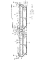
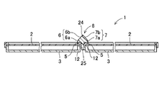
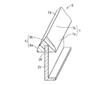
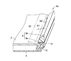
図1は第1の本発明に係るマルチディスプレイ装置1を示す断面図であり、図2は図1に示すマルチディスプレイ装置1の簡素化した斜視図であり、図3は図2の切断面線III−IIIから見た断面図であり、図4は反射部材8を示す一部の拡大斜視図である。なお、図2および図3は、理解を容易にするため、簡略化して示されている。   FIG. 1 is a cross-sectional view showing a multi-display device 1 according to the first aspect of the present invention, FIG. 2 is a simplified perspective view of the multi-display device 1 shown in FIG. 1, and FIG. FIG. 4 is a partial enlarged perspective view showing the reflecting member 8. 2 and 3 are shown in a simplified manner for easy understanding.

本実施形態において、マルチディスプレイ装置1は、平面的に縦横に並んで配置される表示パネルとしての複数の液晶パネル2と、各液晶パネル2が装着されるシャーシ3と、筐体4と、各液晶パネル2に表示面側(図1の上方)から装着され、各液晶パネル2を各シャーシ3に保持する非表示部である額縁5と、各液晶パネル2の互いに隣接する各額縁5に設けられ、各額縁5よりも面内側の表示領域の出射光を反射する反射面6,7を有する反射部材8と、光学シート9と、拡散板10とを含んで構成される。   In the present embodiment, the multi-display device 1 includes a plurality of liquid crystal panels 2 as display panels arranged side by side in a plane, a chassis 3 on which each liquid crystal panel 2 is mounted, a housing 4, Mounted on the liquid crystal panel 2 from the display surface side (upper side in FIG. 1) and provided on the frame 5 that is a non-display portion that holds each liquid crystal panel 2 in each chassis 3 and each frame 5 adjacent to each other on each liquid crystal panel The reflection member 8 having the reflection surfaces 6 and 7 that reflect the emitted light in the display area on the inner side of the frame 5, the optical sheet 9, and the diffusion plate 10 are included.

本実施形態において、マルチディスプレイ装置1は、テレビジョン受像機またはパーソナルコンピュータなどにおいて、画像情報を出力することによって、画像を表示画面に表示する表示装置によって実現される。各液晶パネル2は、平板状の形状に形成される。液晶パネル2において、厚み方向Zの2つの向きを前面側Z1および背面側Z2とする。   In the present embodiment, the multi-display device 1 is realized by a display device that displays an image on a display screen by outputting image information in a television receiver or a personal computer. Each liquid crystal panel 2 is formed in a flat plate shape. In the liquid crystal panel 2, two directions in the thickness direction Z are defined as a front side Z1 and a back side Z2.

液晶パネル2は、液晶表示素子によって、背後側からのバックライト11の光によって画像を前面2a側に表示することができる。シャーシ3は、液晶パネル2の固定に用いられる基台であり、液晶パネル2よりも背面2b側に配置される。   The liquid crystal panel 2 can display an image on the front surface 2a side by the light of the backlight 11 from the back side by the liquid crystal display element. The chassis 3 is a base used for fixing the liquid crystal panel 2 and is disposed closer to the back surface 2b than the liquid crystal panel 2.

前記筐体4は、液晶パネル2の固定を補助する複数の部材から成り、分割可能に構成されることが好ましい。筐体4は、枠体12を含んで構成される。枠体12は、乗載部分13と、接触部分14とを有する。乗載部分13は、液晶パネル2を厚み方向Zに見たときの液晶パネル2の外周部の少なくとも一部に、背面2b側から対向する。接触部分14は、外周部に対して液晶パネル2の面方向外方から接触する。額縁5は、液晶パネル2の外周部に前面2a側から対向し、筐体4とともに外周部を挟持する。これによって、液晶パネル2は、額縁5に対して前面2a側への相対的な変位が阻止される。   The casing 4 is preferably composed of a plurality of members that assist in fixing the liquid crystal panel 2 and is configured to be separable. The housing 4 includes a frame body 12. The frame body 12 includes a mounting portion 13 and a contact portion 14. The mounting portion 13 faces at least a part of the outer peripheral portion of the liquid crystal panel 2 when the liquid crystal panel 2 is viewed in the thickness direction Z from the back surface 2b side. The contact portion 14 contacts the outer peripheral portion from the outside in the surface direction of the liquid crystal panel 2. The frame 5 faces the outer peripheral portion of the liquid crystal panel 2 from the front surface 2 a side, and sandwiches the outer peripheral portion together with the housing 4. Accordingly, the liquid crystal panel 2 is prevented from being displaced relative to the frame 5 toward the front surface 2a.

マルチディスプレイ装置1において、液晶パネル2の周囲を面方向外方から囲繞する額縁5は、いわゆる狭額縁化されている。たとえば、マルチディスプレイシステムに用いる場合には、複数のマルチディスプレイ装置1を一方向に沿って、またはマトリクス状に配置する。このとき、互いに隣接するマルチディスプレイ装置1の境目に当たる部分、すなわち額縁5は画像が表示されない非表示部となる。   In the multi-display device 1, the frame 5 that surrounds the periphery of the liquid crystal panel 2 from the outside in the plane direction is a so-called narrow frame. For example, when used in a multi-display system, a plurality of multi-display devices 1 are arranged along one direction or in a matrix. At this time, the portion corresponding to the boundary between the multi-display devices 1 adjacent to each other, that is, the frame 5 is a non-display portion where no image is displayed.

各液晶パネル2に表示される各画像は、本来、面方向に連続する画像であるが、額縁5のZ方向から見た図1において左右方向の幅が大きいと、非表示部の幅が大きくなってしまう。マルチディスプレイシステムに用いるようなマルチディスプレイ装置1では、非表示部の幅をなるべく小さくするために、額縁5の幅を小さくする狭額縁化が求められる。本実施形態において、マルチディスプレイ装置1は、各液晶パネル2の対角線方向に長さが60インチで、縦横比率が9対16の狭額縁化された液晶表示装置である。   Each image displayed on each liquid crystal panel 2 is originally an image continuous in the plane direction. However, if the width in the left-right direction in FIG. 1 as viewed from the Z direction of the frame 5 is large, the width of the non-display portion is large. turn into. In the multi-display device 1 used in the multi-display system, in order to reduce the width of the non-display portion as much as possible, it is necessary to narrow the frame to reduce the width of the frame 5. In the present embodiment, the multi-display device 1 is a liquid crystal display device having a narrow frame with a length of 60 inches in the diagonal direction of each liquid crystal panel 2 and an aspect ratio of 9:16.

前記バックライト11は、液晶パネル2よりも背面側Z2に配置される複数の光源を含んで構成される。バックライト11は、シャーシ3に取付けられ、光源から出射された光は、拡散板10、光学シート9を通過し、さらに液晶パネル2を介してマルチディスプレイ装置1よりも前面側Z1に放射され、画像表示を行う表示光として使用される。光源としては、たとえば冷陰極線管などの蛍光管、LED(Light Emitting Diode)などの各種発光部品を用いることができる。   The backlight 11 includes a plurality of light sources arranged on the back side Z2 with respect to the liquid crystal panel 2. The backlight 11 is attached to the chassis 3, and the light emitted from the light source passes through the diffusion plate 10 and the optical sheet 9, and is further radiated to the front side Z 1 from the multi-display device 1 through the liquid crystal panel 2. Used as display light for image display. As the light source, for example, a fluorescent tube such as a cold cathode ray tube and various light emitting components such as an LED (Light Emitting Diode) can be used.

マルチディスプレイ装置1を、正面から背面側Z2に見て、額縁5および液晶パネル2は長方形に形成される。この長方形は、マルチディスプレイ装置1が映像を表示するときの使用時の設置状態において、縦長に配置されても横長に配置されてもよいが、本実施形態では横長に配置される。   When the multi-display device 1 is viewed from the front to the back side Z2, the frame 5 and the liquid crystal panel 2 are formed in a rectangular shape. The rectangle may be arranged vertically or horizontally in the installed state when the multi-display device 1 displays an image, but is arranged horizontally in the present embodiment.

前記額縁5は、厚み方向Zに垂直な平板状部分15と、平板状部分15に直角に連なり、液晶パネル2をその面方向外方から囲繞する外周部16とを含む。平板状部分15は、枠体12の前記乗載部分13とともに液晶パネル2の外周部分を挟持する。   The frame 5 includes a flat plate-like portion 15 perpendicular to the thickness direction Z and an outer peripheral portion 16 that is connected to the flat plate-like portion 15 at a right angle and surrounds the liquid crystal panel 2 from the outside in the surface direction. The flat plate portion 15 sandwiches the outer peripheral portion of the liquid crystal panel 2 together with the mounting portion 13 of the frame body 12.

液晶パネル2は、図示を省略する2枚の基板を含み、厚み方向Zに見て長方形の板状に形成される。液晶パネル2は、TFT(Thin Film Transistor)等のスイッチング素子を含み、2枚の基板の隙間には液晶が注入されている。液晶パネル2は、背面側Z2のバックライト11からの光が照射されることによって、表示機能を発揮する透過型液晶表示装置である。前記2枚の基板には、液晶パネル2における各画素の駆動制御用のドライバ(ソースドライバ)および配線が設けられている。   The liquid crystal panel 2 includes two substrates that are not shown, and is formed in a rectangular plate shape when viewed in the thickness direction Z. The liquid crystal panel 2 includes a switching element such as a TFT (Thin Film Transistor), and liquid crystal is injected into the gap between the two substrates. The liquid crystal panel 2 is a transmissive liquid crystal display device that exhibits a display function when irradiated with light from the backlight 11 on the back side Z2. The two substrates are provided with drivers (source drivers) and wirings for driving control of each pixel in the liquid crystal panel 2.

筐体4は、液晶パネル2よりも背面側Z2、かつシャーシ3よりも前面側Z1に配置され、シャーシ3に取付けられる。筐体4には、光学シート9、拡散板10、バックライト11および反射シート18が配置される。バックライト11の光源は、たとえば、複数本の蛍光管を含み、各蛍光管は、図示しないランプホルダによってシャーシ3に取付けられる。蛍光管よりも前面側Z1には、拡散板10が配置され、拡散板10よりも前面側Z1には前記光学シート9が配置される。拡散板10および光学シート9は、液晶パネル2に平行に配置される。   The housing 4 is disposed on the back side Z2 with respect to the liquid crystal panel 2 and on the front side Z1 with respect to the chassis 3, and is attached to the chassis 3. In the housing 4, an optical sheet 9, a diffusion plate 10, a backlight 11, and a reflection sheet 18 are disposed. The light source of the backlight 11 includes, for example, a plurality of fluorescent tubes, and each fluorescent tube is attached to the chassis 3 by a lamp holder (not shown). The diffusion plate 10 is disposed on the front side Z1 from the fluorescent tube, and the optical sheet 9 is disposed on the front side Z1 from the diffusion plate 10. The diffusion plate 10 and the optical sheet 9 are arranged in parallel to the liquid crystal panel 2.

拡散板10は、蛍光管から発せられた光を、面方向に拡散することによって、輝度が局所的に偏ることを防止する。光学シート9は、複数の光学シートで構成され、本実施形態では、2枚の光学シート9aおよび光学シート9bによって構成され、たとえばカラーフィルタから成る。   The diffusion plate 10 prevents the luminance from being locally biased by diffusing light emitted from the fluorescent tube in the surface direction. The optical sheet 9 includes a plurality of optical sheets. In the present embodiment, the optical sheet 9 includes two optical sheets 9a and 9b, and includes, for example, a color filter.

拡散板10では、輝度が面方向に偏ることを防ぐために、光の進行方向は、ベクトル成分として、面方向の成分を多く含む。これに対し光学シート9は、面方向のベクトル成分を多く含む光の進行方向を、厚み方向Zの成分を多く含む光の進行方向に変換する。具体的には、光学シート9は、レンズまたはプリズム状に形成される部分が面方向に多数並んで形成され、これによって、厚み方向Zに進行する光の拡散度を小さくする。したがって、マルチディスプレイ装置1による表示において、輝度を上昇させることができる。   In the diffusing plate 10, in order to prevent the luminance from being biased in the surface direction, the traveling direction of light includes many components in the surface direction as vector components. On the other hand, the optical sheet 9 converts the traveling direction of light including a lot of vector components in the plane direction into the traveling direction of light including many components in the thickness direction Z. Specifically, the optical sheet 9 is formed with a large number of lens or prism-shaped portions arranged in the plane direction, thereby reducing the diffusivity of light traveling in the thickness direction Z. Therefore, the luminance can be increased in the display by the multi-display device 1.

シャーシ3は、厚み方向Zに垂直な平板状の底部19と、底部19に連なり底部19から立ち上がる側壁部20と、側壁部20のうち底部19が連なる部分とは反対側の部分に連なり、底部19と平行に広がる平板状のフランジ部21とを含んで形成される。底部19は、厚み方向Zに見て長方形に形成される。   The chassis 3 is connected to a flat bottom portion 19 perpendicular to the thickness direction Z, a side wall portion 20 connected to the bottom portion 19 and rising from the bottom portion 19, and a portion of the side wall portion 20 opposite to a portion where the bottom portion 19 is connected. 19 and a flat plate-like flange portion 21 extending in parallel. The bottom portion 19 is formed in a rectangular shape when viewed in the thickness direction Z.

反射シート18は、前記シャーシ3における底部19の前面側Z1の表面の少なくとも一部と、前記フランジ部21とに接触して配置される。反射シート18は、前記側壁部20に対しては接触して配置されてもよく、また接触せず配置されてもよい。反射シート18の少なくとも前面側Z1に臨む表面は、バックライト11からの光に対して高い反射率、理想的には100%の反射率を有する。   The reflection sheet 18 is disposed in contact with at least a part of the surface of the front side Z1 of the bottom portion 19 in the chassis 3 and the flange portion 21. The reflection sheet 18 may be disposed in contact with the side wall portion 20 or may be disposed without contact. The surface facing at least the front side Z1 of the reflection sheet 18 has a high reflectance with respect to the light from the backlight 11, ideally a reflectance of 100%.

枠体12は、光学シート9および拡散板10の各外周部が乗載される段差部17と、段差部17から背面側Z2に連なり、シャーシ3の側壁部20を内周面側から覆い、シャーシ3に対してビスなどによって連結される第2周壁部22と、段差部17の外周部から前面側Z1に連なって立ち上がる第1周壁部23とを含む。   The frame body 12 is provided with a stepped portion 17 on which the outer peripheral portions of the optical sheet 9 and the diffusion plate 10 are mounted, and the stepped portion 17 is connected to the back side Z2, covering the side wall portion 20 of the chassis 3 from the inner peripheral surface side, A second peripheral wall portion 22 connected to the chassis 3 by screws or the like and a first peripheral wall portion 23 rising from the outer peripheral portion of the stepped portion 17 to the front side Z1 are included.

第1周壁部23の前面側Z1の領域には、前面側Z1に臨み、液晶パネル2の外周部に対向する前記乗載部分13と、乗載部分13よりも面方向外方において前面側Z1に突出し、液晶パネル2に面方向外方から接触する接触部分14とが形成される。この乗載部分13は、液晶パネル2の外周部を額縁5の平板状部分15とともに挟持する部分である。したがって、乗載部分13は、液晶パネル2の外周部に確実に対向する必要があり、また乗載部分13は、面方向の幅を狭く設定するほど、狭額縁化の実現を容易にすることができる。   In the region of the front side Z1 of the first peripheral wall portion 23, the mounting portion 13 that faces the front side Z1 and faces the outer peripheral portion of the liquid crystal panel 2, and the front side Z1 at the outer side of the mounting portion 13 in the plane direction. And a contact portion 14 that contacts the liquid crystal panel 2 from the outside in the surface direction is formed. The mounting portion 13 is a portion that sandwiches the outer peripheral portion of the liquid crystal panel 2 together with the flat portion 15 of the frame 5. Therefore, it is necessary for the mounting portion 13 to surely face the outer peripheral portion of the liquid crystal panel 2, and the mounting portion 13 facilitates the realization of a narrow frame as the width in the plane direction is set narrower. Can do.

液晶パネル2の各辺を成す外周部を支持する乗載部分13について、厚み方向Zおよび各辺の延びる方向に垂直な方向における乗載部分13の寸法を、「幅寸法b1」と称する。マルチディスプレイ装置1の一例として、たとえば各液晶パネル2が60インチのマルチディスプレイ装置1の場合、液晶パネル2のうち画像の表示領域は、およそ長辺方向Xの寸法が133cmで、短辺方向Yの寸法がおよそ75cmである。この場合、乗載部分13の幅寸法b1は、3mm程度に設定される。   Regarding the mounting portion 13 that supports the outer peripheral portion that forms each side of the liquid crystal panel 2, the dimension of the mounting portion 13 in the direction perpendicular to the thickness direction Z and the direction in which each side extends is referred to as a “width dimension b1”. As an example of the multi-display device 1, for example, when each liquid crystal panel 2 is a 60-inch multi-display device 1, the image display area of the liquid crystal panel 2 has a size of about 133 cm in the long side direction X and a short side direction Y The dimension is approximately 75 cm. In this case, the width dimension b1 of the mounting portion 13 is set to about 3 mm.

枠体12において、第2周壁部22は、液晶パネル2の厚み方向Zに平行に形成され、段差部17のうち、液晶パネル2に関する面方向内方の端部に連なり、背面側Z2に延びて形成される。   In the frame body 12, the second peripheral wall portion 22 is formed in parallel with the thickness direction Z of the liquid crystal panel 2, and is connected to the inner end portion in the surface direction of the step portion 17 with respect to the liquid crystal panel 2 and extends to the back side Z 2. Formed.

第1周壁部23は、液晶パネル2の厚み方向Zに平行に形成され、段差部17のうち、液晶パネル2に関する面方向外方の端部に連なり、前面側Z1に延びて形成される。第1周壁部23の前面側Z1には、前面側Z1に臨み、液晶パネル2の外周部に対向する乗載部分13と、乗載部分13よりも面方向外方において前面側Z1に突出し、液晶パネル2の外縁部に面方向外方から接触する接触部分14とが形成される。枠体12の乗載部分13は、液晶パネル2の外周部を額縁5の平板状部分15と協働して挟持する部分である。したがって、乗載部分13は、液晶パネル2の外周部に確実に対向させて安定に支持し、狭額縁化を図ることができる幅寸法b1に選ばれる。   The first peripheral wall portion 23 is formed in parallel to the thickness direction Z of the liquid crystal panel 2, is connected to the outer end portion in the surface direction with respect to the liquid crystal panel 2 in the stepped portion 17, and extends to the front surface side Z <b> 1. The front surface side Z1 of the first peripheral wall portion 23 faces the front surface side Z1, protrudes to the front surface side Z1 on the outer side in the plane direction from the mounting portion 13 facing the outer peripheral portion of the liquid crystal panel 2, A contact portion 14 that contacts the outer edge of the liquid crystal panel 2 from the outside in the surface direction is formed. The mounting portion 13 of the frame body 12 is a portion that sandwiches the outer peripheral portion of the liquid crystal panel 2 in cooperation with the flat plate-like portion 15 of the frame 5. Therefore, the mounting portion 13 is selected to have a width dimension b1 that can be reliably opposed to the outer peripheral portion of the liquid crystal panel 2 and can be stably supported to reduce the frame.

液晶パネル2の厚み方向Zにおいて、接触部分14の幅寸法(深さあるいは高さ寸法)b2は、液晶パネル2の厚み寸法Tに対してほぼ同一でかつわずかに小さく設定される。これによって、額縁5の平板状部分15が液晶パネル2の外周部に接触し、乗載部分13とともに液晶パネル2を挟持するときに、液晶パネル2が厚み方向Zにがたつくことを防止することができる。   In the thickness direction Z of the liquid crystal panel 2, the width dimension (depth or height dimension) b <b> 2 of the contact portion 14 is set to be substantially the same and slightly smaller than the thickness dimension T of the liquid crystal panel 2. This prevents the flat panel portion 15 of the frame 5 from coming into contact with the outer peripheral portion of the liquid crystal panel 2 and prevents the liquid crystal panel 2 from rattling in the thickness direction Z when the liquid crystal panel 2 is sandwiched together with the mounting portion 13. it can.

前記反射部材8は、たとえばアクリル樹脂製の断面形状が山形の柱状部材から成り、各額縁5に沿って延び、かつ頂部を挟んで隣接する2つの斜面に反射面6,7が形成される山形柱状の反射部24と、反射部24に連なり、各液晶パネル2の互いに隣接する額縁5の外周部16によって各液晶パネル2の互いに隣接する各側部によって挟持される挟持部25とを有する。すなわち、挟持部25は各液晶パネル2の互いに隣接する各側部によって、間接的に挟持される。各反射面6,7は、三角柱状の反射部24の裾部、すなわち額縁5側に位置する湾曲部分6a,7aと、この湾曲部分6a,7aより連なり反射部24の頂部側に連なる平坦面6b,7bとによって、断面が三角柱状に形成される。各反射面6,7は、アルミニウム合金等の金属薄膜を前記反射部24の2つの斜面に対して、たとえば蒸着によって形成し、この金属薄膜を白鏡面仕上げ、鏡面加工、メッキ処理などの各種の処理を行うことによって鏡面に加工されて形成される。   The reflection member 8 is formed of a columnar member made of, for example, an acrylic resin and has a mountain-shaped cross-section, and extends along each frame 5 and has reflection surfaces 6 and 7 formed on two inclined surfaces sandwiching the top. It has a columnar reflecting portion 24, and a holding portion 25 that is connected to the reflecting portion 24 and is sandwiched between the adjacent side portions of each liquid crystal panel 2 by the outer peripheral portion 16 of the adjacent frame 5 of each liquid crystal panel 2. That is, the sandwiching portion 25 is indirectly sandwiched by the side portions adjacent to each other of the liquid crystal panels 2. Each reflective surface 6, 7 is a flat surface that is connected to the bottom of the triangular prism-shaped reflective portion 24, that is, the curved portions 6 a, 7 a located on the frame 5 side, and the curved portions 6 a, 7 a and the top side of the reflective portion 24. The cross section is formed in a triangular prism shape by 6b and 7b. Each of the reflecting surfaces 6 and 7 is formed by forming a metal thin film such as an aluminum alloy on the two inclined surfaces of the reflecting portion 24 by, for example, vapor deposition, and performing various processes such as white mirror finishing, mirror finishing, and plating treatment. By processing, it is formed into a mirror surface.

反射部24と挟持部25とは、図1〜図3に示すように一体の成型体から成るものでもよく、あるいは、図4に示すように反射部24の底面から頂部に向って凹状に、かつ反射部24の長手方向に沿って形成された溝30に、挟持部25を嵌め込むことによって接続されるものであってもよい。反射部24は、断面形状が山形であり、各額縁5の各液晶パネル2の一辺を成す部分に全長にわたって延びる棒状体から成る。挟持部25は、断面がL字状の長尺材であり、反射部24の長さ全長にわたって延びていてもよく、また反射部24の長さの全長より短い部材が複数接続されていてもよい。挟持部25は、反射部24と同様にアクリル樹脂から成ってもよく、あるいはポリ塩化ビニル、アルミニウム合金など、その他の素材から成ってもよい。   The reflecting portion 24 and the sandwiching portion 25 may be formed of an integral molded body as shown in FIGS. 1 to 3, or, as shown in FIG. 4, in a concave shape from the bottom surface to the top portion of the reflecting portion 24, And it may be connected by fitting the clamping part 25 into the groove 30 formed along the longitudinal direction of the reflection part 24. The reflecting portion 24 has a mountain shape in cross section, and is composed of a rod-like body that extends over the entire length to a portion that forms one side of each liquid crystal panel 2 of each frame 5. The sandwiching portion 25 is a long material having an L-shaped cross section, and may extend over the entire length of the reflecting portion 24, or a plurality of members shorter than the entire length of the reflecting portion 24 may be connected. Good. The clamping part 25 may be made of an acrylic resin like the reflection part 24, or may be made of other materials such as polyvinyl chloride and an aluminum alloy.

このように挟持部25の断面がL字状に形成されることによって、挟持部25を両側から額縁5によって挟持しかつ片側の枠体12およびシャーシ3によって背面側Z2から係止して抜止めし、反射部材8を各額縁5上に確実に位置決めして保持することができる。また挟持部25は、他の実施形態では、断面が逆T字状に形成されてもよい。挟持部25の断面が逆T字状に形成されることによって、挟持部25を両側から額縁5によって挟持しかつ抜止めして、反射部材8を各額縁5上に確実に位置決めされた状態で抜止めし、安定に保持することができる。また挟持部25は、他の実施形態では、断面がI字状に形成されてもよい。挟持部25の断面がI字状に形成されることによって、マルチディスプレイを設置した後から、各液晶パネル2の互いに隣接する額縁5の各側部の間に挿入し、取付けることができる。   By forming the sandwiching portion 25 in an L shape in this way, the sandwiching portion 25 is sandwiched by the frame 5 from both sides and locked from the back side Z2 by the frame body 12 and the chassis 3 on one side to prevent it from being removed. Thus, the reflecting member 8 can be reliably positioned and held on each frame 5. Moreover, the clamping part 25 may be formed in an inverted T shape in cross section in other embodiments. With the cross-section of the sandwiching portion 25 formed in an inverted T shape, the sandwiching portion 25 is sandwiched and secured by the frame 5 from both sides, and the reflecting member 8 is reliably positioned on each frame 5. It can be secured and kept stable. Moreover, the clamping part 25 may be formed in an I-shaped cross section in other embodiments. Since the cross section of the sandwiching portion 25 is formed in an I shape, the multi-display can be inserted and attached between the side portions of the frame 5 adjacent to each other after the multi-display is installed.

このような反射部材8によって、各液晶パネル2を組立ててマルチディスプレイ装置1を構築した状態での表示画面に、非表示部である各額縁5が線状に露呈することを防止し、表示品位を向上することができる。また、反射部材8は、反射面6,7を有する機械的部品によって実現され、前記従来技術のような電子部品あるいは光ファイバなどの光学部品を用いないため、安価な製造コストで非表示部が露呈しない消費電力の少ないマルチディスプレイ装置1を実現することができる。   Such a reflective member 8 prevents each frame 5 that is a non-display portion from being exposed in a linear manner on the display screen in a state where the liquid crystal panels 2 are assembled and the multi-display device 1 is constructed. Can be improved. Further, the reflecting member 8 is realized by a mechanical part having the reflecting surfaces 6 and 7, and does not use an electronic part or an optical part such as an optical fiber as in the prior art. A multi-display device 1 with low power consumption that is not exposed can be realized.

また、反射部材8は、隣接する各額縁5に沿って延びる2つの表面に反射面6,7が形成される断面形状が山形の柱状部材から成るので、各額縁5の両側の表示画面の表示光を各反射面によってそれぞれ反射し、各額縁5を介して隣接する各表示画面の表示を、外見上、実質的に連続した一連の画像として視認することができ、各額縁5が線状に露見されること防止することができる。したがって、マルチディスプレイ装置1を正面から見ると、上下、左右のそれぞれに額縁5の近辺の画像が反射面6,7によって反射され、その反射像が目に入るために、額縁線を目立たなくすることができる。特に、本実施形態では、反射部材8の反射部24の断面が山形の柱状に形成され、額縁5の線を隠蔽して目立たなくすることができる。   Further, since the reflecting member 8 is formed of a columnar member having a mountain-shaped cross section in which the reflecting surfaces 6 and 7 are formed on two surfaces extending along each adjacent frame 5, the display screens on both sides of each frame 5 are displayed. The light is reflected by each reflecting surface, and the display on each display screen adjacent through each frame 5 can be visually recognized as a substantially continuous series of images, and each frame 5 is linear. It is possible to prevent exposure. Therefore, when the multi-display device 1 is viewed from the front, the images in the vicinity of the frame 5 are reflected by the reflecting surfaces 6 and 7 on the top, bottom, left and right, respectively, and the reflected image enters the eyes, thereby making the frame line inconspicuous. be able to. In particular, in this embodiment, the cross section of the reflecting portion 24 of the reflecting member 8 is formed in a mountain-shaped column shape, and the line of the frame 5 can be concealed so as to be inconspicuous.

さらに、反射部材8は、隣接する各額縁5に沿って延びる2つの表面に反射面6,7が形成される山形柱状の反射部24と、反射部24に連なり、各液晶パネル2の互いに隣接する各側部によって挟持される挟持部25とを有するので、反射部材8を各液晶パネル2の各額縁5に正確に位置決めされた状態で容易かつ確実に設けることができる。   Further, the reflecting member 8 is connected to the reflecting portion 24 having a mountain-shaped columnar shape in which reflecting surfaces 6 and 7 are formed on two surfaces extending along the adjacent frame 5, and adjacent to each other of the liquid crystal panels 2. Therefore, the reflecting member 8 can be provided easily and reliably in a state where the reflecting member 8 is accurately positioned on each frame 5 of each liquid crystal panel 2.

前述の実施形態の反射部材8は、非表示部として額縁5を隠蔽する幅を有する構成について述べたが、本発明の他の実施形態では、額縁5を隠蔽しかつ額縁5よりも内側の液晶パネル2の有効表示領域の外縁まで覆う幅に形成されてもよい。   The reflection member 8 of the above-described embodiment has been described with a configuration having a width that hides the frame 5 as a non-display portion. However, in another embodiment of the present invention, the liquid crystal that hides the frame 5 and is inside the frame 5 is used. The panel 2 may be formed to have a width that covers the outer edge of the effective display area.

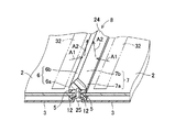
図5は反射部材8が隣接する2つの額縁5に設置された状態を示す一部の斜視図であり、図6は反射部材8がマルチディスプレイ装置1の周縁部の額縁5に設置された状態を示す一部の斜視図である。前述のマルチディスプレイ装置1において、前記反射部材8は、図5に示すように、同一面上で隣接する2つの液晶パネル2の額縁5に設置されるとともに、マルチディスプレイ装置1の周縁部、すなわち面方向外方に配置される額縁5には、図6に示すように、表示画面に臨む斜辺に対応する片側の表面だけに反射面6を有する断面が半山形形状の反射部材8aが、たとえば両面粘着テープ31によって接着されて設けられる。各反射部材8,8aの各反射面6,7は、表示画面の額縁5近傍の反射対象領域32から矢符A1で示すように放射される光を矢符A2で示すように反射するため、額縁5は正面から表示画面を視認する看者には認識されず、実質的に額縁5を隠蔽し、マルチディスプレイ装置1全体としての表示画像の額縁5による表示品位の低下を防止することができる。   FIG. 5 is a partial perspective view showing a state in which the reflecting member 8 is installed in two adjacent frames 5, and FIG. 6 is a state in which the reflecting member 8 is installed in the frame 5 at the peripheral portion of the multi-display device 1. FIG. In the multi-display device 1 described above, the reflecting member 8 is installed on the frame 5 of the two liquid crystal panels 2 adjacent on the same plane as shown in FIG. As shown in FIG. 6, the frame 5 arranged outwardly in the plane direction includes a reflecting member 8 a having a reflecting surface 6 on only one surface corresponding to the oblique side facing the display screen and having a semi-mountain cross section. Adhered by a double-sided adhesive tape 31 is provided. The reflecting surfaces 6 and 7 of the reflecting members 8 and 8a reflect the light emitted from the reflection target region 32 in the vicinity of the frame 5 of the display screen as indicated by the arrow A1, as indicated by the arrow A2. The frame 5 is not recognized by a viewer who visually recognizes the display screen from the front, and the frame 5 is substantially concealed, so that deterioration of display quality due to the frame 5 of the display image as the entire multi-display device 1 can be prevented. .

図6に示すようなマルチディスプレイ装置1の周縁部の額縁5に設けられる反射部材8aは、本発明の他の実施形態においては、表示上の支障がない場合には、省略されてもよい。   The reflective member 8a provided on the frame 5 at the peripheral edge of the multi-display device 1 as shown in FIG. 6 may be omitted in the other embodiment of the present invention when there is no problem in display.

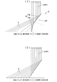
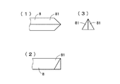
図7は液晶パネル2からの出射光の反射パターンを示す図であり、図7(1)は本実施形態の反射部材8による反射パターンを示す図であり、図7(2)は比較例として反射部材の反射面が傾斜した平面である場合の反射パターンを示す図である。本実施形態の反射部材8による場合、図7(1)に示すように、液晶パネル2の額縁5に近い部分からの出射光をも反射させることができ、これによって、液晶パネル2からの出射光による画像と、反射面6,7からの反射光による画像との違和感をより少なくすることができる。さらに、隣接する液晶パネル2からの出射光による画像の連続的視認性も改良される。これに比べて、図7(2)に示す比較例では、液晶パネル2の額縁5に近い部分からの出射光の反射が充分に成されないため、前記のような違和感や、連続的視認性の点において不充分さがある。   FIG. 7 is a diagram showing a reflection pattern of light emitted from the liquid crystal panel 2, FIG. 7 (1) is a diagram showing a reflection pattern by the reflecting member 8 of this embodiment, and FIG. 7 (2) is a comparative example. It is a figure which shows a reflective pattern in case the reflective surface of a reflective member is a flat plane. In the case of the reflecting member 8 according to the present embodiment, as shown in FIG. 7A, it is possible to reflect the emitted light from the portion near the frame 5 of the liquid crystal panel 2, thereby the light emitted from the liquid crystal panel 2. The uncomfortable feeling between the image by the incident light and the image by the reflected light from the reflecting surfaces 6 and 7 can be further reduced. Furthermore, the continuous visibility of the image by the light emitted from the adjacent liquid crystal panel 2 is also improved. In contrast, in the comparative example shown in FIG. 7 (2), the reflected light from the portion close to the frame 5 of the liquid crystal panel 2 is not sufficiently reflected. There is insufficiency in terms.

なお、額縁5上においては、反転された映像、すなわちマルチディスプレイ装置1に表示される映像に対して、反射部24の長手方向が上下になるように取付けた場合は左右反転像、反射部24の長手方向が左右になるように取付けた場合は上下反転像が表示される。各液晶パネル2の大形画面化および狭額縁化によって、額縁5のサイズは、各液晶パネル2の画面全体のサイズに比較して非常に微細な範囲であるため、反転されていても目立たない。また、文字などの細かい表示の場合、額縁線上にかからないよう、すなわち額縁5が反射面6,7に移り込まないように配置することによって、反転表示を防止することが可能である。しかも、本実施形態では、山形形状の反射部24の裾部に、反射面6,7の一部を成す湾曲部分6a,7aが形成され、これによって、前述のとおり液晶パネル2の額縁5に近い部分からの出射光の反射が充分に成されるから、文字などの細かい表示を反射面6,7に移り込まないように配置することがより容易となる。   On the frame 5, when the reflection unit 24 is mounted so that the longitudinal direction of the reflection unit 24 is up and down with respect to the inverted image, that is, the image displayed on the multi-display device 1, When it is mounted so that its longitudinal direction is left and right, a vertically inverted image is displayed. Due to the large screen and narrow frame of each liquid crystal panel 2, the size of the frame 5 is in a very fine range compared to the size of the entire screen of each liquid crystal panel 2, so it is not noticeable even if it is inverted. . Further, in the case of fine display of characters or the like, it is possible to prevent the reverse display by arranging the frame 5 so as not to lie on the frame line, that is, so that the frame 5 does not move to the reflecting surfaces 6 and 7. In addition, in the present embodiment, the curved portions 6a and 7a forming part of the reflecting surfaces 6 and 7 are formed at the skirt of the mountain-shaped reflecting portion 24, whereby the frame 5 of the liquid crystal panel 2 is formed as described above. Since the outgoing light from the near part is sufficiently reflected, it becomes easier to arrange fine displays such as characters so as not to be transferred to the reflecting surfaces 6 and 7.

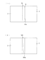
図8はマルチディスプレイ装置1の表示状態を示す正面図であり、図8(1)は額縁5に反射部材8が設けられていないときの画面の表示状態を示し、図8(2)は額縁5に反射部材8を設けたときの画面の表示状態を示す図である。前述のマルチディスプレイ装置1は、図8(2)から明らかなように、反射部材8が額縁5に設けられることによって、互いに隣接する各液晶パネル2間および各液晶パネル2の外周部に配置される各額縁5が、図8(1)のような額縁線が認識されることを防ぎ、表示品位の高い画像を実現することができる。   FIG. 8 is a front view showing a display state of the multi-display device 1, FIG. 8 (1) shows a screen display state when the reflecting member 8 is not provided on the frame 5, and FIG. 8 (2) is a frame. 5 is a diagram showing a display state of a screen when a reflecting member 8 is provided in FIG. As is clear from FIG. 8 (2), the multi-display device 1 described above is disposed between the liquid crystal panels 2 adjacent to each other and at the outer peripheral portion of each liquid crystal panel 2 by providing the reflecting member 8 on the frame 5. Each frame 5 is prevented from recognizing a frame line as shown in FIG. 8A, and an image with high display quality can be realized.

図9は本発明の他の実施形態の反射部材8bを具備するマルチディスプレイ装置1aを示す一部の断面図である。なお、前述の各実施形態と対応する部分には同一の参照符を付す。本実施形態では、反射部材8bは、隣接する各額縁5に沿って延びる2つの表面に前記と同様の反射面6,7が形成される山形柱状の反射部24のみから成り、すなわち、前記のような挟持部25を有さず、かつ隣接する各額縁5に両面粘着テープ31bによって固着される。このような構成によって、反射部材8bを容易に各額縁5へ高い強度で取付けることができる。   FIG. 9 is a partial cross-sectional view showing a multi-display device 1a including a reflecting member 8b according to another embodiment of the present invention. Note that the same reference numerals are given to portions corresponding to the above-described embodiments. In the present embodiment, the reflecting member 8b is composed only of the angled columnar reflecting portion 24 in which the reflecting surfaces 6 and 7 similar to the above are formed on the two surfaces extending along the adjacent frame 5, that is, Such a sandwiching portion 25 is not provided, and is fixed to each adjacent frame 5 by a double-sided adhesive tape 31b. With this configuration, the reflecting member 8b can be easily attached to each frame 5 with high strength.

図10は本発明のさらに他の実施形態の反射部材8cを具備するマルチディスプレイ装置1bを示す一部の断面図である。なお、前述の各実施形態と対応する部分には同一の参照符を付す。本実施形態では、反射部材8cは、隣接する各額縁5に沿って延びる2つの表面に前記と同様の反射面6,7が形成される山形柱状の反射部24のみから成り、すなわち、前記のような挟持部25を有さず、隣接する各額縁5の一方に両面粘着テープ31cによって固着され、かつ各非表示部の他方に帯状にスペーサである合成樹脂製のシート体31dを介して乗載されるので、各非表示部の近接/離反する方向に相対変位しても、反射部材8cは一方の額縁5に両面粘着テープ31cによって固着され、かつ他方の額縁5にシート体31dを介して乗載されるので、反射部材8cが固着されている側の額縁5に追従して移動し、他方の額縁5に固着されたシート体31d上を摺動することができ、前記相対変位を許容することができる。一方の非表示部は他方の非表示部よりも幅が大きいので、反射部材8cを前記一方の非表示部に対して高い強度で接合することができる。   FIG. 10 is a partial cross-sectional view showing a multi-display device 1b including a reflecting member 8c according to still another embodiment of the present invention. Note that the same reference numerals are given to portions corresponding to the above-described embodiments. In the present embodiment, the reflecting member 8c is composed only of the angled columnar reflecting portions 24 in which the reflecting surfaces 6 and 7 similar to the above are formed on two surfaces extending along the adjacent frame 5, that is, Such a sandwiching portion 25 is not provided, and is fixed to one of the adjacent frames 5 by a double-sided adhesive tape 31c, and is placed on the other non-display portion via a synthetic resin sheet body 31d that is a strip-like spacer. Therefore, even if each non-display portion is relatively displaced in the approaching / separating direction, the reflecting member 8c is fixed to one frame 5 by the double-sided adhesive tape 31c, and the other frame 5 via the sheet body 31d. Therefore, it is possible to move following the frame 5 on the side where the reflecting member 8c is fixed and slide on the sheet body 31d fixed to the other frame 5, and the relative displacement can be reduced. Can be tolerated. Since one non-display part is wider than the other non-display part, the reflecting member 8c can be bonded to the one non-display part with high strength.

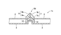
図11は本発明のさらに他の実施形態の反射部材8dを具備するマルチディスプレイ装置1cを示す一部の断面図である。なお、前述の各実施形態と対応する部分には同一の参照符を付す。本実施形態では、反射部材8dが前述の額縁5および枠体12を兼ねた構造体として一体に形成される。これによってもまた、前述の各実施形態と同様に額縁5が線として認識されることを抑制し、または防止することができるとともに、額縁5と反射部材8dとを一体成形によって同時に製造することができ、製造コストの削減を図ることができる。   FIG. 11 is a partial cross-sectional view showing a multi-display device 1c including a reflecting member 8d according to still another embodiment of the present invention. Note that the same reference numerals are given to portions corresponding to the above-described embodiments. In the present embodiment, the reflecting member 8d is integrally formed as a structure that serves as the frame 5 and the frame body 12 described above. Also by this, it is possible to suppress or prevent the frame 5 from being recognized as a line as in the above-described embodiments, and to simultaneously manufacture the frame 5 and the reflecting member 8d by integral molding. The manufacturing cost can be reduced.

図12は本発明のマルチディスプレイ装置1の全体斜視図と、本マルチディスプレイ装置1における反射部材8の交差部Aの一部を拡大して示す斜視図であり、図13は図12の交差部Aの拡大平面図である。図14は図13に示す反射部材8の交差部A側に配置される端部81の構造を示す図であり、図14(1)は反射部材8の端部81の平面図であり、図14(2)は反射部材8の端部81の側面図であり、図14(3)は反射部材8の端部81を図14(2)の右側から見た正面図である。なお、本実施形態の反射部材8の端部81の構成は、前述の各実施形態の反射部材8,8a〜8dの全てに適用可能であるため、反射部材8について説明し、残余の反射部材8a〜8dについては重複を避けて説明は省略する。   12 is an overall perspective view of the multi-display device 1 according to the present invention, and a perspective view showing an enlarged part of the crossing portion A of the reflecting member 8 in the multi-display device 1. FIG. 13 is a cross-sectional view of FIG. It is an enlarged plan view of A. 14 is a view showing the structure of the end portion 81 arranged on the intersection A side of the reflecting member 8 shown in FIG. 13, and FIG. 14 (1) is a plan view of the end portion 81 of the reflecting member 8. FIG. 14 (2) is a side view of the end portion 81 of the reflecting member 8, and FIG. 14 (3) is a front view of the end portion 81 of the reflecting member 8 viewed from the right side of FIG. 14 (2). In addition, since the structure of the edge part 81 of the reflection member 8 of this embodiment is applicable to all the reflection members 8 and 8a-8d of each above-mentioned embodiment, the reflection member 8 is demonstrated and the remaining reflection members The description of 8a to 8d is omitted to avoid duplication.

複数(図12では16)の液晶パネル2が各画像表示面にて共通な一平面を成すようにマトリクス状に配置されたマルチディスプレイ装置1において、前記反射部材8は各額縁5上に前述のように搭載され、複数の交差部Aを有する。各交差部Aでは、各反射部材8の端部81が隙間なく接触した状態とするため、交差部Aにおける各画像表示面を含む共通な仮想一表面に垂直な中心軸線Lに関して軸対称または中心軸線Lを含む仮想一平面に関して面対称に、略三角錐状に形成される。   In the multi-display device 1 in which a plurality of (16 in FIG. 12) liquid crystal panels 2 are arranged in a matrix so as to form a common plane on each image display surface, the reflection member 8 is placed on each frame 5 as described above. And has a plurality of intersections A. In each intersection A, the end portions 81 of the reflecting members 8 are in contact with each other without a gap, so that the axis 81 is symmetrical or centered with respect to a central axis L perpendicular to a common virtual surface including each image display surface in the intersection A. It is formed in a substantially triangular pyramid shape symmetrical with respect to a virtual plane including the axis L.

図15〜図20は第2の本発明に係るマルチディスプレイ装置100を示し、図15はマルチディスプレイ装置100の一実施形態における反射部材50が隣接する2つの額縁5に設置された状態を示す一部の斜視図であり、図16は図5に示す反射部材50における反射面51および非反射面52の額縁5に対する傾斜角度を示す断面図であり、図17は本実施形態のマルチディスプレイ装置100の表示状態を示す正面図の一部である。図17(1)は額縁5に反射部材50が設けられているときの画面の表示状態を示し、図17(2)は比較例として額縁5に3つの角が全て鋭角の三角柱状の反射部材500を設けたときの画面の表示状態を示す図である。また、図18は本実施形態の第1の変形例の反射部材50aを示す一部の拡大斜視図であり、図19は本実施形態の第2の変形例の反射部材50bを示す一部の拡大斜視図である。図20は第2の変形例の反射部材50bを用いたマルチディスプレイ装置100aの全体斜視図と、各部位における反射部材50bの設置態様を示す図である。   15 to 20 show a multi-display device 100 according to the second aspect of the present invention, and FIG. 15 shows a state in which the reflecting member 50 in one embodiment of the multi-display device 100 is installed on two adjacent frames 5. FIG. 16 is a cross-sectional view showing the inclination angle of the reflecting surface 51 and the non-reflecting surface 52 with respect to the frame 5 in the reflecting member 50 shown in FIG. 5, and FIG. 17 is a multi-display device 100 of the present embodiment. It is a part of front view which shows the display state. FIG. 17 (1) shows a display state of the screen when the reflection member 50 is provided on the frame 5, and FIG. 17 (2) shows a triangular prism-like reflection member having all three corners on the frame 5 as a comparative example. It is a figure which shows the display state of a screen when 500 is provided. FIG. 18 is a partial enlarged perspective view showing the reflecting member 50a of the first modification of the present embodiment, and FIG. 19 is a part of the reflecting member 50b of the second modification of the present embodiment. It is an expansion perspective view. FIG. 20 is an overall perspective view of the multi-display device 100a using the reflective member 50b of the second modification, and a diagram showing how the reflective member 50b is installed in each part.

図15および図16において、反射部材50を除くマルチディスプレイ装置100の構成部材は、図5に示す例と同様であるので対応する部分には同一の参照符を付す。本実施形態の反射部材50は、非表示部としての額縁5を覆い、かつ、この額縁5に対して斜めに配される1個の平面状の反射面51を含む。そして、この反射部材50は、たとえばアクリル樹脂から成り、前記平面状の反射面51が形成される反射部53と、各液晶パネル2の互いに隣接する額縁5の各外周部16によって挟持される挟持部54とを有する。本実施形態の反射部53は、底角が鋭角と鈍角の三角形状の柱状体から成り、鋭角側の斜面が反射面51とされ、鈍角側の斜面が非反射面52とされる。反射面51に対して、前記と同様に、アルミニウム合金等の金属薄膜をたとえば蒸着によって形成し、この金属薄膜を白鏡面仕上げ、鏡加工、メッキ処理などの各種の処理を行うことによって鏡面に加工されて形成される。本実施形態では、挟持部54は反射部53とともに樹脂の一体成型によって形成されている。   In FIG. 15 and FIG. 16, the constituent members of the multi-display device 100 excluding the reflecting member 50 are the same as those in the example shown in FIG. The reflecting member 50 of the present embodiment includes a single planar reflecting surface 51 that covers the frame 5 as a non-display portion and is arranged obliquely with respect to the frame 5. The reflecting member 50 is made of, for example, acrylic resin, and is sandwiched between the reflecting portion 53 where the planar reflecting surface 51 is formed and the outer peripheral portions 16 of the frame 5 adjacent to each other of the liquid crystal panels 2. Part 54. The reflecting portion 53 of the present embodiment is formed of a triangular columnar body whose base angle is an acute angle and an obtuse angle. The acute angle side slope is the reflection surface 51, and the obtuse angle side slope is the non-reflection surface 52. As described above, a metal thin film such as an aluminum alloy is formed on the reflecting surface 51 by vapor deposition, for example, and this metal thin film is processed into a mirror surface by performing various processes such as white mirror finishing, mirror processing, and plating. To be formed. In this embodiment, the clamping part 54 is formed by integral molding of resin together with the reflection part 53.

本実施形態において、反射面51の額縁5における平板状部分15に対する傾斜角度αは、45°<α<90°、非反射面52の平板状部分15に対する傾斜角度βは、45°<α≦90°でかつα<βになるよう設定される。これによって、反射部24の底部の幅寸法を隣接する額縁5の両平板状部分15の両端部間寸法に整合するよう設定すれば、平面視において隣接する額縁5が反射面51によって完全に覆われることになる。そして、図15に示すように、反射面51の傾斜立ち上がり基部51a側の液晶パネル2における反射対象領域32から矢符A1で示すように放射される光を、反射面51によって矢符A2で示すように反射するため、額縁5は正面から表示画面を視認する看者には認識されず、実質的に額縁5を隠蔽し、マルチディスプレイ装置1全体としての表示画像の額縁5による表示品位の低下を防止することができる。   In this embodiment, the inclination angle α of the reflecting surface 51 with respect to the flat plate-like portion 15 in the frame 5 is 45 ° <α <90 °, and the inclination angle β of the non-reflecting surface 52 with respect to the flat plate-like portion 15 is 45 ° <α ≦. It is set to 90 ° and α <β. Accordingly, if the width dimension of the bottom portion of the reflecting portion 24 is set so as to match the dimension between both end portions of both flat plate portions 15 of the adjacent frame 5, the adjacent frame 5 is completely covered by the reflecting surface 51 in plan view. It will be. Then, as shown in FIG. 15, the light emitted as indicated by the arrow A <b> 1 from the reflection target region 32 in the liquid crystal panel 2 on the inclined rising base 51 a side of the reflection surface 51 is indicated by the arrow A <b> 2 by the reflection surface 51. Therefore, the frame 5 is not recognized by a viewer who visually recognizes the display screen from the front. The frame 5 is substantially hidden, and the display quality is deteriorated by the frame 5 of the display image of the multi-display device 1 as a whole. Can be prevented.

図17(1)は、図15および図16に示すように額縁5に反射部材50が設けられているときの画面の表示状態を平面的に示しており、前記反射対象領域32からの放射光が平面状の反射面51の全面から反射されるから、この反射光画像には、反射対象領域32からの放射光画像以外の筋などが視認されない。これに対して図17(2)に示すように、断面形状が三角形の反射部材500(たとえば、前記先願に開示された反射部材)を用いると、その反射光画像の中央部に三角形の頂部に対応する線500aが視認される。   FIG. 17A is a plan view showing a screen display state when the reflecting member 50 is provided on the frame 5 as shown in FIGS. 15 and 16, and the emitted light from the reflection target region 32. Is reflected from the entire surface of the planar reflecting surface 51, and therefore, a line other than the radiation light image from the reflection target region 32 is not visually recognized in the reflected light image. On the other hand, as shown in FIG. 17 (2), when a reflecting member 500 having a triangular cross-sectional shape (for example, the reflecting member disclosed in the prior application) is used, the top of the triangle is formed at the center of the reflected light image. A line 500a corresponding to is visually recognized.

図18は、本実施形態の第1の変形例の反射部材50aを示す一部の拡大斜視図である。この例では、反射部53が平板状部材から成り、この平板状の反射部53が挟持部54に対して所定の傾斜角度となるよう一体に固定されている。そして、反射部53の挟持部54による固定部とは反対側の傾斜面が反射面51とされている。   FIG. 18 is a partial enlarged perspective view showing the reflecting member 50a of the first modification of the present embodiment. In this example, the reflecting portion 53 is made of a flat plate member, and this flat plate-like reflecting portion 53 is fixed integrally with the holding portion 54 so as to have a predetermined inclination angle. And the inclined surface on the opposite side to the fixing part by the clamping part 54 of the reflection part 53 is used as the reflection surface 51.

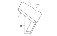
また、図19は、第2の変形例の反射部材50bを示す一部の拡大斜視図である。この例では、反射部53が第1の変形例と同様に平板状部材から成るが、反射部53は断面形状が直状(I字状)の挟持部55に対して、該挟持部55の上端に反射部材50bの長手方向に沿って固着された支持軸56の軸線56a回りに回動可能に連結され、反射面51の前記額縁5に対する傾斜角度α(図16参照)が調整可能とされている。そして、挟持部55がI字状に形成されることによって、マルチディスプレイを設置した後から、各液晶パネル2の互いに隣接する額縁5の各外周部16の間に挿入し、取付けることができるとともに、額縁5からの反射部材50bの突出高さを調整することができる。反射部53の下面には、前記支持軸56に同心的に嵌合する断面扇形(扇角が180°以上)の開環状の嵌合部材57が固着されている。嵌合部材57の内径は、支持軸56の外径よりやや小とされ、嵌合部材57は支持軸56に対してフリクションを持って嵌合されている。したがって、反射部材50bは、嵌合部材57の支持軸56に対する嵌合によって、支持軸56の軸線56a回りに回動可能に支持されるとともに、任意の回動位置に保持され、反射面51の傾斜角度αの任意設定が可能とされている。   FIG. 19 is a partial enlarged perspective view showing the reflecting member 50b of the second modification. In this example, the reflecting portion 53 is made of a flat plate member as in the first modification. However, the reflecting portion 53 has a cross-sectional shape that is straight (I-shaped). It is connected to the upper end so as to be rotatable around the axis 56a of the support shaft 56 fixed along the longitudinal direction of the reflecting member 50b, and the inclination angle α (see FIG. 16) of the reflecting surface 51 with respect to the frame 5 can be adjusted. ing. And since the clamping part 55 is formed in I shape, after installing a multi-display, it can insert and attach between each outer peripheral part 16 of the mutually adjacent frame 5 of each liquid crystal panel 2. The protrusion height of the reflecting member 50b from the frame 5 can be adjusted. An open annular fitting member 57 having a sectional fan shape (fan angle is 180 ° or more) concentrically fitted to the support shaft 56 is fixed to the lower surface of the reflecting portion 53. The inner diameter of the fitting member 57 is slightly smaller than the outer diameter of the support shaft 56, and the fitting member 57 is fitted to the support shaft 56 with friction. Therefore, the reflection member 50b is supported so as to be rotatable around the axis 56a of the support shaft 56 by fitting the fitting member 57 to the support shaft 56, and is held at an arbitrary rotation position. Arbitrary setting of the inclination angle α is possible.

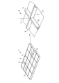
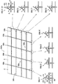
図20は、第2の変形例の反射部材50bを用いたマルチディスプレイ装置100aの模式的全体斜視図と、各部位における反射部材50bの設置態様を側面して示す模式図である。このマルチディスプレイ装置100aは、5×5(=25)枚の液晶パネル2をマトリックス状に並べて構成されている。マルチディスプレイ装置100aの周縁部分には、額縁(図示せず)のみで反射部材50bは設けられていない。そして、隣接する各額縁5間には反射部材50bが設けられるが、縦方向(上下方向)には、縦方向全長に亘り連続する反射部材50bが各1本ずつ計4本設けられ、横方向(左右方向)には、隣接する液晶パネル2毎に反射部材50bが計20本設けられている。左右方向に並ぶ縦向きの4本の反射部材50b(1)〜50b(4)のうち、左右両端の反射部材50b(1),50b(4)は、反射面51が互いに向き合うとともに、反射面51の傾斜角度が大きく設定され、かつ、額縁5からの突出位置が高くなるよう挟持部55が隣接する額縁5間に挟持されている。また、中間部の反射部材50b(2),50b(3)は、反射面51が互いに向き合うとともに、反射部材50b(1),50b(4)より反射面51の傾斜角度が小さく設定され、かつ、額縁5からの突出位置が低くなるよう挟持部55が隣接する額縁5間に挟持されている。さらに、上下方向に並ぶ横向きの反射部材50b(5)〜50b(8)は、いずれも反射面51が下方に向けられ、上端の反射部材50b(5)から下端の反射部材50b(8)にかけて、反射面51の傾斜角度が徐々に小さくなるよう設定され、かつ、額縁5からの突出位置が徐々に低くなるよう挟持部55が隣接する額縁5間に挟持されている。   FIG. 20 is a schematic overall perspective view of a multi-display device 100a using the reflective member 50b of the second modified example, and a schematic view showing the installation mode of the reflective member 50b in each part in a side view. The multi-display device 100a is configured by arranging 5 × 5 (= 25) liquid crystal panels 2 in a matrix. The reflection member 50b is not provided only on the frame (not shown) at the peripheral portion of the multi-display device 100a. A reflecting member 50b is provided between the adjacent frame frames 5. In the longitudinal direction (vertical direction), four reflecting members 50b that are continuous over the entire length in the longitudinal direction are provided, one in each, in the lateral direction. In the left-right direction, a total of 20 reflecting members 50 b are provided for each adjacent liquid crystal panel 2. Of the four vertical reflecting members 50b (1) to 50b (4) arranged in the left-right direction, the reflecting members 50b (1), 50b (4) at the left and right ends have the reflecting surface 51 facing each other and the reflecting surface The sandwiching portion 55 is sandwiched between the adjacent frame 5 so that the inclination angle 51 is set large and the protruding position from the frame 5 is higher. Further, the reflecting members 50b (2) and 50b (3) in the middle part have the reflecting surface 51 facing each other, and the inclination angle of the reflecting surface 51 is set smaller than that of the reflecting members 50b (1) and 50b (4), and The sandwiching portion 55 is sandwiched between the adjacent frame 5 so that the protruding position from the frame 5 is lowered. Further, in the horizontal reflecting members 50b (5) to 50b (8) arranged in the vertical direction, the reflecting surface 51 is directed downward, and from the upper reflecting member 50b (5) to the lower reflecting member 50b (8). The holding portion 55 is sandwiched between the adjacent frames 5 so that the inclination angle of the reflecting surface 51 is gradually decreased and the protruding position from the frame 5 is gradually decreased.

なお、横向きの反射部材50b(5)〜50b(8)においては、各列の横方向に並ぶ各5本の反射部材50bは、それぞれ同様の設置態様とされる。   In the horizontal reflecting members 50b (5) to 50b (8), each of the five reflecting members 50b arranged in the horizontal direction of each row has the same installation mode.

図20に示すような大画面のマルチディスプレイ装置100aの場合、看者はマルチディスプレイ装置100aの中央の少し離れた位置からやや見上げるように位置することが想定される。したがって、前記のような態様で各反射部材50bを設置することによって、反射部材50bによる表示画面からの反射光が看者の視点に集まりやすくなり、額縁5が露呈して表示品位が低下することを可及的に少なくすることができる。   In the case of a large-screen multi-display device 100a as shown in FIG. 20, it is assumed that the viewer is positioned so as to look up slightly from a position slightly away from the center of the multi-display device 100a. Therefore, by installing each reflecting member 50b in the above-described manner, the reflected light from the display screen by the reflecting member 50b is likely to gather at the viewer's viewpoint, and the frame 5 is exposed to reduce the display quality. Can be reduced as much as possible.

図21は、第3の本発明に係るマルチディスプレイ装置200の一実施形態における反射部材60が隣接する2つの額縁5に設置された状態を示す一部の斜視図である。また、図22は図21に示す反射部材60による液晶パネル2からの出射光の反射パターンを示す図である。図21において、反射部材60を除くマルチディスプレイ装置200の構成部材は、図5に示す例と同様であるので対応する部分には同一の参照符を付す。本実施形態の反射部材60は、断面形状が三角形の柱状部材から成り、2つの斜面による反射面61,62を有する反射部63と、この反射部63に連なり、隣接する額縁5の各外周部16に挟持される挟持部64とを含む。前記反射面61は、粗面化処理部65を含む。図21の拡大部は、粗面化処理部65を誇張して示す拡大断面図である。粗面化処理部65は、反射面61の全面に亘り形成してもよいが、本実施形態では、額縁5から離れるに従って粗面化度合いが大きくなるよう形成されている。粗面化処理部65は、ショットブラスト、エッチング処理、その他の公知の処理法によって形成される。   FIG. 21 is a partial perspective view showing a state in which the reflection member 60 in one embodiment of the multi-display device 200 according to the third aspect of the present invention is installed on two adjacent frames 5. FIG. 22 is a diagram showing a reflection pattern of emitted light from the liquid crystal panel 2 by the reflecting member 60 shown in FIG. In FIG. 21, the constituent members of the multi-display apparatus 200 excluding the reflecting member 60 are the same as those in the example shown in FIG. The reflecting member 60 of the present embodiment includes a columnar member having a triangular cross-sectional shape, and a reflecting portion 63 having reflecting surfaces 61 and 62 with two inclined surfaces, and each outer peripheral portion of the adjacent frame 5 connected to the reflecting portion 63. 16 and a clamping part 64 that is clamped by 16. The reflection surface 61 includes a roughening processing unit 65. The enlarged portion of FIG. 21 is an enlarged cross-sectional view showing the roughening processing portion 65 in an exaggerated manner. The roughening processing unit 65 may be formed over the entire reflecting surface 61, but in this embodiment, the roughening processing unit 65 is formed so that the degree of roughening increases as the distance from the frame 5 increases. The roughening processing section 65 is formed by shot blasting, etching processing, or other known processing methods.

このような反射部材60が設けられたマルチディスプレイ装置200においては、液晶パネル2の反射対象領域32から矢符A1で示すように放射される光は、反射部材60の反射面61によって反射される。このとき、反射面61には粗面化処理部65が形成されているから、この粗面化処理部65によって図21の矢符A2,A3、および図22の反射光で示すように乱反射する。この乱反射によって、反射映像をぼやかすことができる。本実施形態では、粗面化処理部65が、額縁5から離れるに従って粗面化度合いが大きくなるよう形成されているから、隣接する液晶パネル2からの反射映像が違和感なく視覚される。特に、反射部分で反転することにより、その部分が目立ち、見づらくなるような映像が多用される場合には、額縁5から離れるに従ってぼやけた映像を表示させることは、スムーズな表示に有効である。   In the multi-display device 200 provided with such a reflection member 60, the light emitted from the reflection target region 32 of the liquid crystal panel 2 as indicated by the arrow A1 is reflected by the reflection surface 61 of the reflection member 60. . At this time, since the roughening processing unit 65 is formed on the reflection surface 61, the roughening processing unit 65 performs irregular reflection as indicated by the arrows A2 and A3 in FIG. 21 and the reflected light in FIG. . This irregular reflection can blur the reflected image. In the present embodiment, since the roughening processing unit 65 is formed so that the degree of roughening increases as the distance from the frame 5 increases, the reflected image from the adjacent liquid crystal panel 2 is visually recognized. In particular, in the case where an image that makes the portion conspicuous and becomes difficult to see by being inverted at the reflection portion is often used, displaying a blurred image as the distance from the frame 5 is effective for smooth display.

なお、第3の本発明に係る粗面化処理部を、第1および第2の本発明に係る反射部材8、50にも適用することは可能である。これによって、第1および第2の本発明と、第3の本発明との複合した効果が得られる。また、第1および第3の本発明においても、看者の視点Bが最も集まりやすい位置を想定して反射方向を設定した反射部材を実装してマルチディスプレイ装置を構成することによって、それぞれの反射部材が表示画面からの光を反射し、額縁5が露呈して表示品位が低下することを可及的に少なくすることができる。また、図9〜図11に示す実施形態を第2の本発明あるいは第3の本発明に適用することも可能である。   Note that the roughening treatment section according to the third aspect of the present invention can also be applied to the reflecting members 8 and 50 according to the first and second aspects of the present invention. As a result, the combined effects of the first and second aspects of the present invention and the third aspect of the present invention are obtained. Also in the first and third aspects of the present invention, each reflection can be achieved by configuring a multi-display device by mounting a reflection member whose reflection direction is set on the assumption that the viewer's viewpoint B is most likely to gather. It is possible to reduce as much as possible that the member reflects light from the display screen and the frame 5 is exposed and the display quality is deteriorated. Also, the embodiment shown in FIGS. 9 to 11 can be applied to the second invention or the third invention.

1,1a,1b,1c,100,100a,200 マルチディスプレイ装置
2 液晶パネル
3 シャーシ
4 筐体
5 額縁
6,7,51,61 反射面
6a,7a 湾曲部分
8,8b,8c,8d,50,50a,50b,60 反射部材
24,54,55,64 挟持部
15 平板状部分
16 外周部
56a 軸線
65 粗面化処理部
Z1 前面側
Z2 背面側
α 傾斜角度
1, 1a, 1b, 1c, 100, 100a, 200 Multi-display device 2 Liquid crystal panel 3 Chassis 4 Case 5 Frame 6, 7, 51, 61 Reflecting surface 6a, 7a Curved portion 8, 8b, 8c, 8d, 50, 50a, 50b, 60 Reflective member 24, 54, 55, 64 Nipping part 15 Flat part 16 Outer part 56a Axis 65 Surface roughening part Z1 Front side Z2 Back side α Inclination angle

Claims (10)

画像を表示する表示領域と、該表示領域を外囲する非表示部とを有し、互いに隣接して設けられる複数の表示パネルと、
前記非表示部に設けられ、前記表示領域からの出射光を反射する反射面を有する反射部材であって、前記反射面に外方に凸に湾曲した湾曲部分が設けられる反射部材とを含むことを特徴とするマルチディスプレイ装置。
A plurality of display panels provided adjacent to each other, each having a display region for displaying an image and a non-display portion surrounding the display region;
A reflective member that is provided in the non-display portion and has a reflective surface that reflects light emitted from the display region, the reflective member having a curved portion curved outwardly on the reflective surface. A multi-display device characterized by the above.
前記反射部材は、前記非表示部から突出する2つの斜面を有する三角柱状の長尺材から成り、各斜面に前記反射面が形成される反射部を有し、該反射部の反射面の前記非表示部側の部分に、前記湾曲部分が形成されることを特徴とする請求項1に記載のマルチディスプレイ装置。   The reflecting member is made of a triangular prism-like long material having two inclined surfaces protruding from the non-display portion, and has a reflecting portion on which the reflecting surface is formed, and the reflecting surface of the reflecting portion has the reflecting surface. The multi-display apparatus according to claim 1, wherein the curved portion is formed in a portion on a non-display portion side. 前記反射部材は、前記湾曲部分を含む2つの反射面が形成される反射部と、該反射部に連なり、前記各表示パネルの互いに隣接する各非表示部によって挟持される挟持部とを有することを特徴とする請求項2に記載のマルチディスプレイ装置。   The reflective member includes a reflective portion in which two reflective surfaces including the curved portion are formed, and a sandwiching portion that is connected to the reflective portion and is sandwiched between non-display portions adjacent to each other of the display panels. The multi-display apparatus according to claim 2. 画像を表示する表示領域と、該表示領域を外囲する非表示部とを有し、互いに隣接して設けられる複数の表示パネルと、
前記非表示部に設けられ、前記表示領域からの出射光を反射する反射面を有する反射部材であって、前記反射面が、前記非表示部を覆い、かつ、該非表示部に対して傾斜した1つの平面状の反射面から成ることを特徴とするマルチディスプレイ装置。
A plurality of display panels provided adjacent to each other, each having a display region for displaying an image and a non-display portion surrounding the display region;
A reflective member provided in the non-display portion and having a reflective surface for reflecting light emitted from the display region, the reflective surface covering the non-display portion and inclined with respect to the non-display portion A multi-display device comprising one planar reflecting surface.
前記反射部材は、前記平面状の反射面が形成される反射部と、該反射部に連なり、前記各表示パネルの互いに隣接する各非表示部によって挟持される挟持部とを有することを特徴とする請求項4に記載のマルチディスプレイ装置。   The reflective member includes a reflective portion in which the planar reflective surface is formed, and a sandwiching portion that is connected to the reflective portion and is sandwiched between non-display portions adjacent to each other of the display panels. The multi-display device according to claim 4. 前記反射部は、前記挟持部に対して、反射部材の長手方向に沿った軸線まわりに回動可能に連結され、前記反射面の前記非表示部に対する傾斜角度が調整可能に構成されることを特徴とする請求項5に記載のマルチディスプレイ装置。   The reflection portion is connected to the sandwiching portion so as to be rotatable about an axis along the longitudinal direction of the reflection member, and the inclination angle of the reflection surface with respect to the non-display portion is configured to be adjustable. 6. The multi-display device according to claim 5, wherein 画像を表示する表示領域と、該表示領域を外囲する非表示部とを有し、互いに隣接して設けられる複数の表示パネルと、
前記非表示部に設けられ、前記表示領域からの出射光を反射する反射面を有する反射部材であって、前記反射面が、粗面化された粗面化処理部を含むことを特徴とするマルチディスプレイ装置。
A plurality of display panels provided adjacent to each other, each having a display region for displaying an image and a non-display portion surrounding the display region;
A reflection member provided in the non-display portion and having a reflection surface that reflects light emitted from the display region, wherein the reflection surface includes a roughening treatment portion that is roughened. Multi display device.
前記反射部材は、前記非表示部から突出する2つの斜面を有し、かつ断面形状が三角形の柱状部材から成り、各斜面に前記反射面が形成されることを特徴とする請求項7に記載のマルチディスプレイ装置。   The said reflecting member has two inclined surfaces which protrude from the said non-display part, and a cross-sectional shape consists of a columnar member with a triangle, The said reflective surface is formed in each inclined surface, The said reflecting surface is formed. Multi-display device. 前記反射面の粗面化処理部は、前記非表示部から突出方向に向かって粗度が大きくなるように形成されることを特徴とする請求項8に記載のマルチディスプレイ装置。   The multi-display apparatus according to claim 8, wherein the roughening processing unit of the reflection surface is formed so that the roughness increases from the non-display unit in a protruding direction. 前記反射部材は、前記2つの反射面が形成される反射部と、該反射部に連なり、前記各表示パネルの互いに隣接する各非表示部によって挟持される挟持部とを有することを特徴とする請求項8または9に記載のマルチディスプレイ装置。   The reflective member includes a reflective portion in which the two reflective surfaces are formed, and a sandwiching portion that is connected to the reflective portion and is sandwiched between the non-display portions adjacent to each other of the display panels. The multi-display device according to claim 8 or 9.
JP2010256349A 2010-09-14 2010-11-16 Multi display device Active JP5722004B2 (en)

Priority Applications (2)

Application Number Priority Date Filing Date Title
JP2010256349A JP5722004B2 (en) 2010-11-16 2010-11-16 Multi display device
PCT/JP2011/069931 WO2012035988A1 (en) 2010-09-14 2011-09-01 Multi-display device

Applications Claiming Priority (1)

Application Number Priority Date Filing Date Title
JP2010256349A JP5722004B2 (en) 2010-11-16 2010-11-16 Multi display device

Publications (2)

Publication Number Publication Date
JP2012108270A true JP2012108270A (en) 2012-06-07
JP5722004B2 JP5722004B2 (en) 2015-05-20

Family

ID=46493965

Family Applications (1)

Application Number Title Priority Date Filing Date
JP2010256349A Active JP5722004B2 (en) 2010-09-14 2010-11-16 Multi display device

Country Status (1)

Country Link
JP (1) JP5722004B2 (en)

Cited By (5)

* Cited by examiner, † Cited by third party
Publication number Priority date Publication date Assignee Title
JP2016168277A (en) * 2015-03-13 2016-09-23 株式会社三共 Game machine
JP2017006186A (en) * 2015-06-17 2017-01-12 株式会社三共 Game machine
JP2017049367A (en) * 2015-08-31 2017-03-09 シャープ株式会社 Display device and electronic apparatus
JP2017221537A (en) * 2016-06-17 2017-12-21 株式会社三共 Game machine
US11092835B2 (en) 2019-03-20 2021-08-17 Sakai Display Products Corporation Display apparatus having light guide member with tapered optical fibers

Citations (6)

* Cited by examiner, † Cited by third party
Publication number Priority date Publication date Assignee Title
JPS61250674A (en) * 1985-04-30 1986-11-07 沖電気工業株式会社 Large display unit
JPH04101582U (en) * 1991-02-08 1992-09-02 株式会社エヌケービー large display device
JP2003322875A (en) * 2002-05-03 2003-11-14 Taida Electronic Ind Co Ltd Composite liquid crystal panel
JP2005003989A (en) * 2003-06-12 2005-01-06 Seiko Epson Corp Picture display device
JP2006308707A (en) * 2005-04-27 2006-11-09 Hitachi Displays Ltd Display apparatus
JP3157886U (en) * 2009-12-18 2010-03-04 岡谷電機産業株式会社 Display device

Patent Citations (6)

* Cited by examiner, † Cited by third party
Publication number Priority date Publication date Assignee Title
JPS61250674A (en) * 1985-04-30 1986-11-07 沖電気工業株式会社 Large display unit
JPH04101582U (en) * 1991-02-08 1992-09-02 株式会社エヌケービー large display device
JP2003322875A (en) * 2002-05-03 2003-11-14 Taida Electronic Ind Co Ltd Composite liquid crystal panel
JP2005003989A (en) * 2003-06-12 2005-01-06 Seiko Epson Corp Picture display device
JP2006308707A (en) * 2005-04-27 2006-11-09 Hitachi Displays Ltd Display apparatus
JP3157886U (en) * 2009-12-18 2010-03-04 岡谷電機産業株式会社 Display device

Cited By (5)

* Cited by examiner, † Cited by third party
Publication number Priority date Publication date Assignee Title
JP2016168277A (en) * 2015-03-13 2016-09-23 株式会社三共 Game machine
JP2017006186A (en) * 2015-06-17 2017-01-12 株式会社三共 Game machine
JP2017049367A (en) * 2015-08-31 2017-03-09 シャープ株式会社 Display device and electronic apparatus
JP2017221537A (en) * 2016-06-17 2017-12-21 株式会社三共 Game machine
US11092835B2 (en) 2019-03-20 2021-08-17 Sakai Display Products Corporation Display apparatus having light guide member with tapered optical fibers

Also Published As

Publication number Publication date
JP5722004B2 (en) 2015-05-20

Similar Documents

Publication Publication Date Title
JP4481245B2 (en) Curved liquid crystal display device and method for forming and installing reflector or reflector sheet for curved liquid crystal display device
JP6261505B2 (en) Curved bezel concealed display device cover and display device without bezel
JP5378569B2 (en) Display device and electronic device
KR101426726B1 (en) Multi-screen dispaly device having a transparent cover of invisible bezel
JP5269983B2 (en) Display device
JP4787224B2 (en) Seamless display manufacturing method
KR102634179B1 (en) Display device
JP2009162999A (en) Image display device and multi-display system
JPWO2012102349A1 (en) Multi-display system and translucent cover used therefor
JP2005017491A (en) Liquid crystal display device
JP5722004B2 (en) Multi display device
WO2012035988A1 (en) Multi-display device
JP4465862B2 (en) Large screen display device
JP5622498B2 (en) Multi display device
JP2012150366A (en) Light guide member and multi-display device including the same
WO2013046604A1 (en) Display device and multi-display device
KR101589959B1 (en) Bezel free multi-screen display device with flat panel transparent cover and fastening device of flat panel transparent cover
KR102355821B1 (en) Display Device having Multiple Display Panel
JP4483233B2 (en) Surface light source and liquid crystal display device
JP5722005B2 (en) Multi display device
CN115167033B (en) Backlight module, display device and spliced display device
JP4882109B2 (en) Display device
JP2003157031A (en) Multi-display device
JP2017097256A (en) Display device
KR102344296B1 (en) Display Device having Multiple Display Panel and Plate-type Optical Member therefor

Legal Events

Date Code Title Description
A621 Written request for application examination

Free format text: JAPANESE INTERMEDIATE CODE: A621

Effective date: 20131001

A131 Notification of reasons for refusal

Free format text: JAPANESE INTERMEDIATE CODE: A131

Effective date: 20141007

A521 Written amendment

Free format text: JAPANESE INTERMEDIATE CODE: A523

Effective date: 20141121

TRDD Decision of grant or rejection written
A01 Written decision to grant a patent or to grant a registration (utility model)

Free format text: JAPANESE INTERMEDIATE CODE: A01

Effective date: 20150303

A61 First payment of annual fees (during grant procedure)

Free format text: JAPANESE INTERMEDIATE CODE: A61

Effective date: 20150325

R150 Certificate of patent or registration of utility model

Ref document number: 5722004

Country of ref document: JP

Free format text: JAPANESE INTERMEDIATE CODE: R150