JP2012107663A - Blind rivet and fastening method thereof - Google Patents
Blind rivet and fastening method thereof Download PDFInfo
- Publication number
- JP2012107663A JP2012107663A JP2010255623A JP2010255623A JP2012107663A JP 2012107663 A JP2012107663 A JP 2012107663A JP 2010255623 A JP2010255623 A JP 2010255623A JP 2010255623 A JP2010255623 A JP 2010255623A JP 2012107663 A JP2012107663 A JP 2012107663A
- Authority
- JP
- Japan
- Prior art keywords
- sleeve
- mandrel
- flange
- rivet
- washer
- Prior art date
- Legal status (The legal status is an assumption and is not a legal conclusion. Google has not performed a legal analysis and makes no representation as to the accuracy of the status listed.)
- Granted
Links
- 238000000034 method Methods 0.000 title claims description 11
- 230000002093 peripheral effect Effects 0.000 claims abstract description 8
- 230000000149 penetrating effect Effects 0.000 claims description 3
- 239000000463 material Substances 0.000 description 3
- 229910000831 Steel Inorganic materials 0.000 description 2
- 229910052751 metal Inorganic materials 0.000 description 2
- 239000002184 metal Substances 0.000 description 2
- 239000010959 steel Substances 0.000 description 2
- 229910000838 Al alloy Inorganic materials 0.000 description 1
- 229910052782 aluminium Inorganic materials 0.000 description 1
- XAGFODPZIPBFFR-UHFFFAOYSA-N aluminium Chemical compound [Al] XAGFODPZIPBFFR-UHFFFAOYSA-N 0.000 description 1
Images


Classifications
-
- F—MECHANICAL ENGINEERING; LIGHTING; HEATING; WEAPONS; BLASTING
- F16—ENGINEERING ELEMENTS AND UNITS; GENERAL MEASURES FOR PRODUCING AND MAINTAINING EFFECTIVE FUNCTIONING OF MACHINES OR INSTALLATIONS; THERMAL INSULATION IN GENERAL
- F16B—DEVICES FOR FASTENING OR SECURING CONSTRUCTIONAL ELEMENTS OR MACHINE PARTS TOGETHER, e.g. NAILS, BOLTS, CIRCLIPS, CLAMPS, CLIPS OR WEDGES; JOINTS OR JOINTING
- F16B19/00—Bolts without screw-thread; Pins, including deformable elements; Rivets
- F16B19/04—Rivets; Spigots or the like fastened by riveting
- F16B19/08—Hollow rivets; Multi-part rivets
- F16B19/10—Hollow rivets; Multi-part rivets fastened by expanding mechanically
- F16B19/1027—Multi-part rivets
- F16B19/1036—Blind rivets
- F16B19/1045—Blind rivets fastened by a pull - mandrel or the like
- F16B19/1063—Blind rivets fastened by a pull - mandrel or the like with a sleeve or collar sliding over the hollow rivet body during the pulling operation
-
- F—MECHANICAL ENGINEERING; LIGHTING; HEATING; WEAPONS; BLASTING
- F16—ENGINEERING ELEMENTS AND UNITS; GENERAL MEASURES FOR PRODUCING AND MAINTAINING EFFECTIVE FUNCTIONING OF MACHINES OR INSTALLATIONS; THERMAL INSULATION IN GENERAL
- F16B—DEVICES FOR FASTENING OR SECURING CONSTRUCTIONAL ELEMENTS OR MACHINE PARTS TOGETHER, e.g. NAILS, BOLTS, CIRCLIPS, CLAMPS, CLIPS OR WEDGES; JOINTS OR JOINTING
- F16B19/00—Bolts without screw-thread; Pins, including deformable elements; Rivets
- F16B19/04—Rivets; Spigots or the like fastened by riveting
- F16B19/08—Hollow rivets; Multi-part rivets
- F16B19/10—Hollow rivets; Multi-part rivets fastened by expanding mechanically
- F16B19/1027—Multi-part rivets
- F16B19/1036—Blind rivets
- F16B19/1045—Blind rivets fastened by a pull - mandrel or the like
- F16B19/1054—Blind rivets fastened by a pull - mandrel or the like the pull-mandrel or the like being frangible
-
- F—MECHANICAL ENGINEERING; LIGHTING; HEATING; WEAPONS; BLASTING
- F16—ENGINEERING ELEMENTS AND UNITS; GENERAL MEASURES FOR PRODUCING AND MAINTAINING EFFECTIVE FUNCTIONING OF MACHINES OR INSTALLATIONS; THERMAL INSULATION IN GENERAL
- F16B—DEVICES FOR FASTENING OR SECURING CONSTRUCTIONAL ELEMENTS OR MACHINE PARTS TOGETHER, e.g. NAILS, BOLTS, CIRCLIPS, CLAMPS, CLIPS OR WEDGES; JOINTS OR JOINTING
- F16B43/00—Washers or equivalent devices; Other devices for supporting bolt-heads or nuts
-
- Y—GENERAL TAGGING OF NEW TECHNOLOGICAL DEVELOPMENTS; GENERAL TAGGING OF CROSS-SECTIONAL TECHNOLOGIES SPANNING OVER SEVERAL SECTIONS OF THE IPC; TECHNICAL SUBJECTS COVERED BY FORMER USPC CROSS-REFERENCE ART COLLECTIONS [XRACs] AND DIGESTS
- Y10—TECHNICAL SUBJECTS COVERED BY FORMER USPC
- Y10T—TECHNICAL SUBJECTS COVERED BY FORMER US CLASSIFICATION
- Y10T29/00—Metal working
- Y10T29/49—Method of mechanical manufacture
- Y10T29/49826—Assembling or joining
- Y10T29/49947—Assembling or joining by applying separate fastener
- Y10T29/49954—Fastener deformed after application
- Y10T29/49956—Riveting
Landscapes
- Engineering & Computer Science (AREA)
- General Engineering & Computer Science (AREA)
- Mechanical Engineering (AREA)
- Insertion Pins And Rivets (AREA)
Abstract
【課題】被取付部材の取付孔の内径が、リベット本体のフランジの外径より大きくても、パネルを締結することができるブラインドリベット。
【解決手段】取付孔を有する複数の被取付部材を締結するためのブラインドリベットは、スリーブ(11)とフランジ(12)と貫通孔(13)を有するリベット本体(10)と、細長い軸部(21)と頭部(23)とを有するマンドレル(20)と、ワッシャ(30)とを備える。マンドレルの頭部が、リベット本体のスリーブ側端部に隣接して配置され、マンドレルの軸部は、リベット本体の貫通孔を通ってフランジ側端部から延び出るように組み合わされ、ワッシャはリベット本体のスリーブの外周にフランジに隣接して取付けられる。フランジに隣接するスリーブの外周面の一部をスエージング加工して凹部を形成し、他の位置の外径を大きくし、ワッシャを押し込んで固定する。スリーブの拡径した端部とワッシャの間に被取付部材を締結する。
【選択図】図7A blind rivet capable of fastening a panel even when an inner diameter of a mounting hole of a mounted member is larger than an outer diameter of a flange of a rivet body.
A blind rivet for fastening a plurality of attached members having attachment holes includes a sleeve (11), a flange (12), a rivet body (10) having a through hole (13), an elongated shaft portion ( 21) and a mandrel (20) having a head (23) and a washer (30). The mandrel head is arranged adjacent to the sleeve end of the rivet body, the shaft of the mandrel is combined so as to extend from the flange end through the through hole of the rivet body, and the washer is combined with the rivet body. Attached to the outer periphery of the sleeve adjacent to the flange. A part of the outer peripheral surface of the sleeve adjacent to the flange is swaged to form a recess, the outer diameter of the other position is increased, and the washer is pushed in and fixed. The member to be attached is fastened between the end of the sleeve whose diameter is increased and the washer.
[Selection] Figure 7
Description
本発明は、ブラインドリベットに関する。特に、ワッシャを有するブラインドリベットにより、大きい取付孔を有する被取付部材を締結することができるブラインドリベット及びその締結方法に関する。 The present invention relates to blind rivets. In particular, the present invention relates to a blind rivet that can fasten a mounted member having a large mounting hole by a blind rivet having a washer and a fastening method thereof.
スリーブ及びそのスリーブの一端のフランジからなる中空の金属製リベット本体と、リベット本体を貫通してスリーブのフランジから軸部が延び出る金属製マンドレルを包含するブラインドリベットは良く知られている。ブラインドリベットは、複数のパネルを一方の側からだけの作業で連結できるという利点がある。
ブラインドリベットのリベット本体は、一端にフランジが形成され、フランジから延びる筒状の中空スリーブを有する。ブラインドリベットのマンドレルは、スリーブの内径より大径の頭部を端部に有し、リベット本体を貫通する外径の軸部を有する。マンドレルは、リベット本体のフランジとは反対側のスリーブの一端部にマンドレルの頭部が隣接配置されて、フランジから軸部が延び出るようにリベット本体の貫通孔に挿入されて、ブラインドリベットとして組み付けられる。ブラインドリベットをマンドレルの頭部を先頭にして、パネル等の被取付部材の孔に挿入し、スリーブのフランジを被取付部材の孔の周囲に当接させる。この状態で、スリーブのフランジを締結工具で保持して、マンドレルの軸部を把持してリベットのフランジ側から強く引き抜くと、リベット本体のスリーブの一端部が拡径するように変形し、マンドレルは軸部の細い破断可能部で破断し、リベット本体のフランジと拡径したスリーブの一端部の間にパネル等の被取付部材を締結することができる。
A blind rivet including a hollow metal rivet body including a sleeve and a flange at one end of the sleeve and a metal mandrel extending through the rivet body and extending from the flange of the sleeve is well known. The blind rivet has an advantage that a plurality of panels can be connected by an operation only from one side.
The rivet body of the blind rivet has a cylindrical hollow sleeve having a flange formed at one end and extending from the flange. The mandrel of the blind rivet has a head having a diameter larger than the inner diameter of the sleeve at the end, and has an outer diameter shaft portion penetrating the rivet body. The mandrel is inserted into the through-hole of the rivet body so that the head part of the mandrel is adjacent to one end of the sleeve opposite to the flange of the rivet body, and the shaft part extends from the flange, and assembled as a blind rivet. It is done. The blind rivet is inserted into the hole of the attached member such as a panel with the head of the mandrel at the head, and the flange of the sleeve is brought into contact with the periphery of the hole of the attached member. In this state, holding the sleeve flange with a fastening tool, gripping the mandrel shaft and pulling it strongly from the flange side of the rivet, the one end of the sleeve of the rivet body is deformed so that its diameter increases, A member to be attached such as a panel can be fastened between the flange of the rivet body and one end portion of the sleeve whose diameter has been expanded.
従来のブラインドリベットは、リベット本体のフランジの外径が、締結する被取付部材の孔の内径より大きいことが前提である。リベット本体のフランジの外径が、締結する被取付部材の孔の内径より小さいと、パネルを締結することができなかった。
そのため、被取付部材の孔径に合わせて、フランジ径の異なる色々のリベット本体を用意しておく必要があった。
The conventional blind rivet is premised on the outer diameter of the flange of the rivet body being larger than the inner diameter of the hole of the attached member to be fastened. If the outer diameter of the flange of the rivet body is smaller than the inner diameter of the hole of the attached member to be fastened, the panel could not be fastened.
Therefore, it is necessary to prepare various rivet bodies having different flange diameters in accordance with the hole diameter of the attached member.
特許文献1は、自己閉塞タイプのブラインドリベットを開示する。特許文献1のブラインドリベットは、胴とその一端のリベット頭を有するリベット本体と、軸幹テール部と折れやすい部分により接続され螺旋状の溝が形成されプラグ体と、端部を有する軸幹とを備える。ブラインドリベットを締結すると、リベット頭の材料が螺旋状の溝に入り締結される。リベット頭を回転させると、比較的容易にリベットの締結を解除することができる。
しかし、特許文献2のブラインドリベットは、締結するパネルの孔径がリベット本体のフランジ径より大きいと、ブラインドリベットを締結することができなかった。
Patent Document 1 discloses a self-closing type blind rivet. The blind rivet of Patent Document 1 includes a barrel, a rivet main body having a rivet head at one end thereof, a plug body that is connected to a shaft tail portion by a portion that is easily broken, a plug body, and a shaft having an end portion. Is provided. When the blind rivet is fastened, the material of the rivet head enters the spiral groove and is fastened. When the rivet head is rotated, the fastening of the rivet can be released relatively easily.
However, the blind rivet of Patent Document 2 cannot be fastened if the hole diameter of the panel to be fastened is larger than the flange diameter of the rivet body.
そのため、締結するパネルの孔の内径が、リベット本体のフランジの外径より大きくても、パネルを締結することができるブラインドリベットが求められていた。
色々の孔径の被取付部材を締結することができるブラインドリベットが求められていた。
Therefore, there has been a demand for a blind rivet that can fasten the panel even if the inner diameter of the hole of the panel to be fastened is larger than the outer diameter of the flange of the rivet body.
There has been a demand for blind rivets capable of fastening attachment members having various hole diameters.
従って、本発明の目的は、締結するパネル等の被取付部材の孔の内径が、リベット本体のフランジの外径より大きくても、パネルを締結することができるブラインドリベットを提供することである。
また、色々の孔径の被取付部材を締結することができるブラインドリベットを提供することである。
Accordingly, an object of the present invention is to provide a blind rivet capable of fastening a panel even if the inner diameter of a hole of a member to be attached such as a panel to be fastened is larger than the outer diameter of a flange of a rivet body.
Moreover, it is providing the blind rivet which can fasten the to-be-attached member of various hole diameters.
この目的を達成するため、本発明では、リベット本体のフランジに隣接して、締結するパネルの孔の内径より大きい外径のワッシャを取り付け、大きい取付孔を有するパネルを締結することができるようにする。 In order to achieve this object, in the present invention, a washer having an outer diameter larger than the inner diameter of the hole of the panel to be fastened is attached adjacent to the flange of the rivet body so that a panel having a large mounting hole can be fastened. To do.
本発明の第1の態様は、取付孔を有する複数の被取付部材を締結するためのブラインドリベットであって、
中空のスリーブと、前記スリーブの一端に形成されたフランジとを有し、スリーブ側端部からフランジ側端部まで貫通する貫通孔が形成されたリベット本体と、
前記スリーブの内径より小さい外径で前記リベット本体より長い細長い軸部と、前記スリーブの内径より大きい外径の頭部とを有するマンドレルと、
前記フランジの外径より小さい内径で、前記フランジの外径より大きい外径のワッシャとを備え、
前記マンドレルの前記頭部が、前記リベット本体の前記スリーブ側端部に隣接して配置され、前記マンドレルの前記軸部は、前記リベット本体の前記貫通孔を通って前記フランジ側端部から延び出るように組み合わされ、前記ワッシャは前記リベット本体の前記スリーブの外周に前記フランジに隣接して取付けられているブラインドリベットである。
その結果、締結する被取付部材の孔の内径が、リベット本体のフランジの外径より大きくても、被取付部材を締結することができる。
A first aspect of the present invention is a blind rivet for fastening a plurality of attached members having attachment holes,
A rivet body having a hollow sleeve and a flange formed at one end of the sleeve, and having a through hole penetrating from the sleeve side end to the flange side end;
A mandrel having an elongated shaft portion having an outer diameter smaller than the inner diameter of the sleeve and longer than the rivet body, and a head portion having an outer diameter larger than the inner diameter of the sleeve;
A washer having an inner diameter smaller than the outer diameter of the flange and an outer diameter larger than the outer diameter of the flange;
The head portion of the mandrel is disposed adjacent to the sleeve side end portion of the rivet body, and the shaft portion of the mandrel extends from the flange side end portion through the through hole of the rivet body. The washer is a blind rivet attached to the outer periphery of the sleeve of the rivet body adjacent to the flange.
As a result, the attached member can be fastened even if the inner diameter of the hole of the attached member to be fastened is larger than the outer diameter of the flange of the rivet body.
前記リベット本体の前記フランジに隣接する前記スリーブの外周面の一部を押し込み加工して凹部を形成し、前記凹部と異なる位置の前記スリーブの外径を大きくした拡径部に、前記ワッシャを押し込んで取付けることができる。 A portion of the outer peripheral surface of the sleeve adjacent to the flange of the rivet body is pressed to form a recess, and the washer is pressed into an enlarged diameter portion where the outer diameter of the sleeve is increased at a position different from the recess. Can be installed at.
前記凹部は、前記スリーブの外周面の円周方向に反対側の2箇所に形成され、前記スリーブの外周面上の前記凹部の間の部分を外径が大きい拡径部とすることができる。
こうすると、拡径部にワッシャの内周を嵌め込んで固定することができる。
The concave portions are formed at two locations on the outer circumferential surface of the sleeve opposite to each other in the circumferential direction, and a portion between the concave portions on the outer circumferential surface of the sleeve can be an enlarged portion having a large outer diameter.
If it carries out like this, the inner periphery of a washer can be fitted and fixed to an enlarged diameter part.
前記凹部を形成する加工は、前記リベット本体と前記マンドレルとを組み合わせた状態で行うことができる。
こうすると、凹部を加工するときに、リベット本体のスリーブの内径が変形しにくく、マンドレルがリベット本体に固定されること、又はリベット本体に挿入できなくなることはない。
The processing for forming the concave portion can be performed in a state where the rivet body and the mandrel are combined.
In this way, when processing the recess, the inner diameter of the sleeve of the rivet body is not easily deformed, and the mandrel is not fixed to the rivet body or cannot be inserted into the rivet body.
前記リベット本体の前記フランジに隣接する前記スリーブの外周面を半径方向の両側から押して断面を楕円形とし、前記スリーブの外径を大きくした長径部に、前記ワッシャを押し込んで固定することができる。
こうすると、簡単にスリーブに外径の大きい部分を形成し、ワッシャの内周を固定することができる。
前記リベット本体の前記スリーブの外周部の前記フランジに隣接する部分に凸部を成形しておき、前記凸部に前記ワッシャを押し込んで固定することができる。
The outer peripheral surface of the sleeve adjacent to the flange of the rivet body can be pushed from both sides in the radial direction to make the cross section elliptical, and the washer can be pushed into and fixed to the long diameter portion with the outer diameter of the sleeve increased.
In this way, a portion having a large outer diameter can be easily formed on the sleeve, and the inner periphery of the washer can be fixed.
A convex portion can be formed in a portion adjacent to the flange of the outer peripheral portion of the sleeve of the rivet body, and the washer can be pushed into the convex portion and fixed.
前記被取付部材を締結するとき、前記ブラインドリベットを前記マンドレルの頭部から、前記被取付部材の取付孔に挿入し、前記ワッシャの面を前記被取付部材の前記取付孔の周りに当接し、
前記リベット本体の前記フランジを支持して、前記フランジの側から前記マンドレルの前記軸部を引き抜くとき、前記スリーブの端部が、前記頭部により押されて拡径し、前記スリーブの拡径した端部と、前記ワッシャとの間に前記被取付部材を締結するブラインドリベットでもよい。
When fastening the mounted member, the blind rivet is inserted into the mounting hole of the mounted member from the head of the mandrel, and the surface of the washer abuts around the mounting hole of the mounted member,
When supporting the flange of the rivet body and pulling out the shaft portion of the mandrel from the flange side, the end of the sleeve is pushed by the head to increase the diameter, and the diameter of the sleeve is increased. A blind rivet that fastens the attached member between an end and the washer may be used.
被取付部材を締結するとき、前記マンドレルは、前記軸部の小径の破断可能部で破断し、前記破断可能部から前記頭部の側は締結部に残留するブラインドリベットでもよい。 When the attachment member is fastened, the mandrel may be a blind rivet that breaks at a breakable portion having a small diameter of the shaft portion and the head side from the breakable portion remains in the fastening portion.
本発明の第2の態様は、被取付部材をブラインドリベットで締結する方法であって、
中空のスリーブと、前記スリーブの一端のフランジを有し、貫通孔が形成されたリベット本体と、
前記スリーブの内径より小さい外径で前記スリーブより長い細長い軸部と、前記スリーブの内径より大きい外径の頭部とを有するマンドレルと、
前記フランジの外径より小さい内径で、前記フランジの外径より大きい外径のワッシャとを用意し、
前記リベット本体と前記マンドレルとワッシャとを組み合わせて、ブラインドリベットとし、
前記ブラインドリベットを前記マンドレルの頭部から、前記被取付部材の取付孔に挿入し、前記ワッシャの面を前記被取付部材の前記取付孔の周りに当接し、
前記リベット本体の前記フランジを支持して、前記フランジの側から前記マンドレルの前記軸部を引き抜き、前記スリーブの端部が、前記頭部により押されて拡径し、前記スリーブの拡径した端部と、前記ワッシャとの間に前記被取付部材を締結する、
段階を備えることを特徴とする方法である。
A second aspect of the present invention is a method of fastening a mounted member with a blind rivet,
A hollow sleeve, a rivet body having a flange at one end of the sleeve and having a through-hole formed therein;
A mandrel having an elongated shaft portion having an outer diameter smaller than the inner diameter of the sleeve and longer than the sleeve; and a head having an outer diameter larger than the inner diameter of the sleeve;
A washer having an inner diameter smaller than the outer diameter of the flange and an outer diameter larger than the outer diameter of the flange;
The rivet body, the mandrel and the washer are combined to form a blind rivet,
The blind rivet is inserted from the head of the mandrel into the mounting hole of the mounted member, and the surface of the washer abuts around the mounting hole of the mounted member,
The flange of the rivet body is supported, the shaft portion of the mandrel is pulled out from the flange side, and the end of the sleeve is pushed by the head to expand the diameter, and the diameter-expanded end of the sleeve Fastening the attached member between the portion and the washer;
A method comprising the steps.
前記リベット本体と前記マンドレルとワッシャとを組み合わせて、ブラインドリベットとする段階は、
前記リベット本体のスリーブ側端部から、前記マンドレルを先端部から前記貫通孔に挿入し、前記マンドレルの前記頭部が前記スリーブ側端部に当接して止まり、
前記リベット本体の前記スリーブの一部を押し込み加工して凹部を形成し、前記凹部と異なる位置の前記スリーブの外径を大きくして拡径部とし、
前記ワッシャを前記マンドレルの前記頭部の側から前記拡径部に押し込んで固定することを備えることができる。
The step of combining the rivet body, the mandrel and the washer into a blind rivet includes:
From the sleeve side end of the rivet body, the mandrel is inserted into the through hole from the tip, and the head of the mandrel abuts against the sleeve side end and stops,
A part of the sleeve of the rivet body is pressed to form a recess, and the outer diameter of the sleeve at a position different from the recess is increased to form an enlarged diameter part,
The washer may be fixed by being pushed into the enlarged diameter portion from the head side of the mandrel.
本発明によれば、締結する被取付部材の孔の内径が、リベット本体のフランジの外径より大きくても、被取付部材を締結することができるブラインドリベットを得ることができる。
また、異なる外径のワッシャと組み合わせれば、色々の孔径の被取付部材を締結することができるブラインドリベットを得ることができる。
ADVANTAGE OF THE INVENTION According to this invention, even if the internal diameter of the hole of the to-be-attached member to fasten is larger than the outer diameter of the flange of a rivet main body, the blind rivet which can fasten a to-be-attached member can be obtained.
Further, when combined with washers having different outer diameters, blind rivets capable of fastening attachment members having various hole diameters can be obtained.
以下、図面を参照して、本発明の実施形態によるワッシャを備えるブラインドリベットについて説明する。 Hereinafter, a blind rivet including a washer according to an embodiment of the present invention will be described with reference to the drawings.
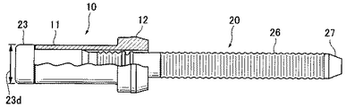
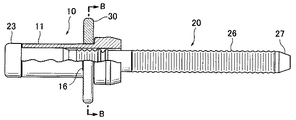
図1は、本発明の実施形態のブラインドリベットの一部を断面とした正面図である。ブラインドリベットは、リベット本体10と、マンドレル20とを含む。リベット本体10のスリーブ側端部14から、マンドレル20を挿入し、マンドレル20の頭部23が、リベット本体10のスリーブ側端部14に隣接するように配置されている。
FIG. 1 is a front view of a section of a blind rivet according to an embodiment of the present invention. The blind rivet includes a
以下、図2〜4を参照して、ブラインドリベットを構成するリベット本体10と、マンドレル20と、ワッシャ30について説明する。
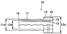
図2は、本発明の実施形態のブラインドリベットに使用するリベット本体10の一部を断面とした正面図である。リベット本体10は、円筒状のスリーブ11と、スリーブ11の一端に形成され、スリーブ11より大径のフランジ12とを含む。フランジ12の先端部は、テーパ状に外径が小さくなる斜面部19となり、フランジ側端部15で終わる。斜面部19は、ブラインドリベットを締結するとき、締結工具の把持部材51により外周から押され内径が小さくなる。
Hereinafter, the
FIG. 2 is a front view in which a part of the
スリーブ11のフランジ12と反対側はスリーブ側端部14である。リベット本体10のフランジ側端部15と、スリーブ側端部14との間に貫通孔13が延びる。貫通孔13の内径13dは、マンドレル20の軸部21を挿入できる大きさであるが、マンドレル20の頭部23の外径より小さく、頭部23がスリーブ側端部14に当接して止まるようになっている。
スリーブ11の外径11dは、被取付部材の取付孔の直径より少し小さく、取付孔を通ることができる大きさである。
リベット本体10は、マンドレル20より軟質の材料、例えばアルミニウム、アルミニウム合金等で作られる。又は、マンドレル20と同じスチール等で作ることもできる。
On the opposite side of the
The
The
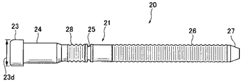
図3は、本発明の実施形態のブラインドリベットに使用するマンドレル20の正面図である。マンドレル20は、細長い軸部21と、軸部21の一端部の頭部23とを備える。頭部23の外径23dは、リベット本体10の貫通孔13の内径13dより大きい。頭部23の外径23dは、被取付部材40の取付孔42の内径42dより小さく、取付孔42を通ることができる。軸部21は円柱状で、リベット本体10の貫通孔13の内径13dより小さい外径を有し、貫通孔13内に挿入することができる。軸部21の長さは、リベット本体10の貫通孔13の長さより長く、マンドレル20の軸部21をリベット本体10の貫通孔13に挿入すると、軸部21の先端は、リベット本体10のフランジ側端部15から突き出す。
FIG. 3 is a front view of the
マンドレル20の軸部21は、頭部23の側から、円柱部24と、係止部28と、破断可能部25と、把持部26と、先端部27とを含む。頭部23に隣接して、円柱状の円柱部24がある。円柱部24の外径は、貫通孔13の内径13dより若干大きく、貫通孔13に圧入する。これにより、マンドレルのスリーブからの抜けを防止している。
円柱部24に隣接して、係止部28がある。係止部28には周上に離間した周溝が形成され、溝の間は係止山となっている。ブラインドリベットを締結するとき、フランジ12の部分が外周より押されて内径が小さくなり、係止山は、内径が小さくなった貫通孔13の内周に係合し、マンドレルの部分がリベット本体10から脱落しないようにする。
The
Adjacent to the
係止部28に隣接して、係止部28より外径の小さい、破断可能部25がある。破断可能部25は、ブラインドリベットを組み立てた状態で、リベット本体10の貫通孔13に収容される部分にある。破断可能部25は、締結工具でマンドレル20の軸部21を引き抜くとき、ある引抜力を超えると破断する部分である。
破断可能部25に隣接して、破断可能部25より径の大きい把持部26がある。把持部26には締結工具で把持する場合スリップしないように多段の係止溝が形成されている。軸部21の先端部27は先が細くなり、締結工具に挿入しやすいように、先が細くなっている。
マンドレル20の材質はスチール等である。
Adjacent to the locking
Adjacent to the
The material of the
図4は、本発明の実施形態のブラインドリベットに使用するワッシャ30の断面図である。ワッシャ30は、中心部分に軸方向に断面が円形の中心孔31が開いた円板状の部材である。中心孔31の内径31dは、マンドレル20の頭部23の外径23dより少し大きく、スリーブ11の外径11dとほぼ等しいか少し大きく、マンドレル20とリベット本体10を組み合わせたブラインドリベットに、マンドレル20の頭部23の側から、ワッシャ30をスリーブ11に挿入することができる。中心孔31の内径31dは、スリーブ11を少し変形させ膨らんだ拡径部を形成すると、ワッシャ30はスリーブ11の外周上に固定されるような大きさである。
FIG. 4 is a cross-sectional view of the
図5〜8を参照して、ブラインドリベットについて、リベット本体10のスリーブ11の一部を押し込んでスエージング加工し、スリーブ11の一部の外形の大きくなった部分に、ワッシャ30を押し込み、本発明の実施形態のワッシャ付きブラインドリベットとする工程を説明する。
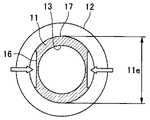
図5は、本発明の実施形態のブラインドリベットのリベット本体10のスリーブ11の一部を押し込んでスエージング加工した状態を示す一部を断面とした正面図である。図6は、図5のブラインドリベットのA−A断面の拡大断面図である。
まず、リベット本体10とマンドレル20を組み合わせる。リベット本体10のスリーブ側端部14から、マンドレル20を先端部27を先頭にして、貫通孔13に挿入していく。マンドレル20の頭部23がスリーブ側端部14に当接して止まる。
5-8, with respect to the blind rivet, a part of the
FIG. 5 is a front view, partly in section, showing a state in which a part of the
First, the
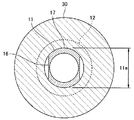
次に、リベット本体10とマンドレル20を組み合わせたブラインドリベットについて、スエージング加工機により、リベット本体10のスリーブ11の半径方向に反対側の2箇所を、押し込み加工して、凹部16を形成する。このとき、凹部16と直角方向のスリーブ11の外径は、元の外径11dから少し大きい外径11eの拡径部17になる。
ワッシャ30の中心孔31の内径31dは、スリーブ11の拡大した拡径部17の外径11eより少し小さく、ワッシャ30を拡径部17に押し込むと固定されるようになっている。
Next, with respect to the blind rivet in which the rivet
The
スエージング加工は、リベット本体10とマンドレル20を組み合わせた状態で行うのが好ましい。リベット本体10に凹部16を形成するとき、貫通孔13の内周がマンドレルの軸部で支えられ、貫通孔13の内周が変形することがないからである。又は、リベット本体10の貫通孔13に、貫通孔13の内径に適合した硬質の円柱状の部材を入れた状態でスエージング加工し、その後マンドレル20と組み合わせることもできる。
The swaging process is preferably performed in a state where the
本実施形態では、リベット本体10のスリーブ11の外周部のフランジ12に隣接する部分に凹部16を形成した。凹部16を形成しなくても、スリーブ11の半径方向反対側の2箇所を押して、スリーブ11の部分を楕円形にし、その長径がワッシャ30の中心孔31の内径31dより少し大きい拡径部となるように成形して、拡径部にワッシャ30を固定しても良い。
又は、リベット本体10のスリーブ11の外周部のフランジ12に隣接する部分に凸部を成形しておき、凸部がワッシャ30の内径に係合するようにして固定することもできる。
In the present embodiment, the
Alternatively, a convex portion may be formed in a portion adjacent to the
図7は、図5のブラインドリベットにワッシャ30を取付けた後の状態を示す一部を断面とした正面図である。図8は、図7のブラインドリベットのB−B断面の拡大断面図である。
ワッシャ30をスリーブ11に挿入し、拡径部17に押し込んで固定する。こうして、本発明の実施形態のワッシャ付きブラインドリベットができる。
FIG. 7 is a front view, partly in section, showing a state after the
The
図9〜11を参照して、本発明の実施形態のブラインドリベットにより、被取付部材40,41を締結する動作について説明する。図9は、ブラインドリベットを被取付部材40,41にセットした状態を示す一部を断面とした正面図である。図9の左側がブラインド側であり、右側からブラインドリベットを取り付ける作業をする。
With reference to FIGS. 9-11, the operation | movement which fastens the to-
図9では、被取付部材40の取付孔43は、被取付部材41の取付孔42より大きい。被取付部材40の取付孔43の内径は、フランジ12の外径12dより大きい。この場合、従来のブラインドリベットでは、フランジが被取付部材40の取付孔43に入ってしまうため、被取付部材40と41を締結することはできなかった。本発明の実施形態では、被取付部材40の取付孔43の内径より大きい外径のワッシャ30を使用するので、被取付部材40と41を締結することができる。
In FIG. 9, the mounting
被取付部材40と41を被取付部材40の取付孔43と被取付部材41の取付孔42の位置があうように重ね合わせる。
リベット本体10とマンドレル20を組み合わせワッシャ30を取付けた図7のブラインドリベットを被取付部材40,41の孔に図9の右側から挿入し、リベット本体10に取付けたワッシャ30が被取付部材40の取付孔43の周りの表面に当接するようにする。
The mounted
The blind rivet of FIG. 7 in which the
図10は、ブラインドリベットにより被取付部材40を締結する中間段階を示す一部を断面とした正面図である。取付工具のノーズピース50でリベット本体10のフランジ12の先端に近い斜面部19を保持しながら、マンドレル20の把持部26を取付工具の把持部材51で把持して引き抜いていく。このとき、マンドレル20の頭部23は、リベット本体10のスリーブ11のスリーブ側端部14を押し潰し、膨張部18を形成する。膨張部18は被取付部材41の取付孔42の周りに当接する。
FIG. 10 is a front view, partly in section, showing an intermediate stage in which the attached
図11は、マンドレル20の把持部26を更に引き抜き、ブラインドリベットにより被取付部材40,41を締結した状態を示す一部を断面とした正面図である。ノーズピース50は、フランジ20の斜面部19を外周から押しながら、フランジ20の外径12dを径が小さくなるように変形させていき、外径は12d'となる。このとき、フランジ20の部分の貫通孔13の内周は、内径13dより径が小さくなるように変形し、マンドレル20の係止部28の係止山に係合する。
FIG. 11 is a front view, partly in section, showing a state in which the gripping
ノーズピース50は、その先端の面がワッシャ30の表面に当接すると停止する。ブラインドリベットは、拡径した膨張部18と、ワッシャ30との間に被取付部材40,41を挟む。その後、マンドレル20は、破断可能部25で破断し、破断可能部25から頭部23の側は締結した部分に残る。リベット本体10のフランジ12の内周が、マンドレル20の係止部28に係合するので、ブラインドリベットに残留したマンドレル20の部分は、ブラインドリベットから脱落しない。残留したマンドレル20の部分は、リベット本体10に固く固着するので、高い締結力を得ることができる。この後、ノーズピース50を図11の右方向に後退させて、締結は完了する。
The
ブラインドリベットで被取付部材を締結する場合、通常は、被取付部材の取付孔の内径は、フランジ12の外径12dより小さい。本発明の実施形態では、取付孔43の内径は、フランジ12の外径12dより大きいが、取付孔43の内径より大きい外径を有するワッシャ30を取り付けてあるので、ワッシャ30が被取付部材40に当接し、被取付部材40と41とを締結することができる。
被取付部材の取付孔の内径が異なる場合は、その内径にあった異なる外径のワッシャを使用すれば、被取付部材を締結することができる。そのため、異なる外径のワッシャを用意しておき、1種類のリベット本体10とマンドレル20を、異なる外径のワッシャと組み合わせることにより、色々の内径の取付孔に対応することができる。
When fastening a member to be attached with a blind rivet, the inner diameter of the attachment hole of the member to be attached is usually smaller than the
When the inner diameters of the mounting holes of the mounted member are different, the mounted member can be fastened by using washers having different outer diameters that match the inner diameter. Therefore, by preparing washers having different outer diameters and combining one type of
10 リベット本体
11 スリーブ
12 フランジ
13 貫通孔
14 スリーブ側端部
15 フランジ側端部
16 凹部
17 拡径部
18 膨張部
19 斜面部
20 マンドレル
21 軸部
23 頭部
24 円中部
25 破断可能部
26 把持部
27 先端部
28 係止山
30 ワッシャ
31 中心孔
40 被取付部材
41 被取付部材
42 取付孔
43 取付孔
50 ノーズピース
51 把持部材
10 Rivet body
11 sleeve
12 Flange
13 Through hole
14 Sleeve end
15 Flange end
16 recess
17 Expanded part
18 Expansion part
19 Slope
20 Mandrel
21 Shaft
23 head
24 yen
25 Breakable part
26 Grip part
27 Tip
28 Locking mountain
30 washer
31 Center hole
40 Mounted member
41 Mounted member
42 Mounting hole
43 Mounting hole
50 Nosepiece
51 Holding member
Claims (9)
中空のスリーブと、前記スリーブの一端に形成されたフランジとを有し、スリーブ側端部からフランジ側端部まで貫通する貫通孔が形成されたリベット本体と、
前記スリーブの内径より小さい外径で前記リベット本体より長い細長い軸部と、前記スリーブの内径より大きい外径の頭部とを有するマンドレルと、
前記フランジの外径より小さい内径で、前記フランジの外径より大きい外径のワッシャとを備え、
前記マンドレルの前記頭部が、前記リベット本体の前記スリーブ側端部に隣接して配置され、前記マンドレルの前記軸部は、前記リベット本体の前記貫通孔を通って前記フランジ側端部から延び出るように組み合わされ、前記ワッシャは前記リベット本体の前記スリーブの外周に前記フランジに隣接して取付けられていることを特徴とするブラインドリベット。 A blind rivet for fastening a plurality of attached members having attachment holes,
A rivet body having a hollow sleeve and a flange formed at one end of the sleeve, and having a through hole penetrating from the sleeve side end to the flange side end;
A mandrel having an elongated shaft portion having an outer diameter smaller than the inner diameter of the sleeve and longer than the rivet body, and a head portion having an outer diameter larger than the inner diameter of the sleeve;
A washer having an inner diameter smaller than the outer diameter of the flange and an outer diameter larger than the outer diameter of the flange;
The head portion of the mandrel is disposed adjacent to the sleeve side end portion of the rivet body, and the shaft portion of the mandrel extends from the flange side end portion through the through hole of the rivet body. A blind rivet characterized in that the washer is attached to the outer periphery of the sleeve of the rivet body adjacent to the flange.
前記リベット本体の前記フランジを支持して、前記フランジの側から前記マンドレルの前記軸部を引き抜くとき、前記スリーブの端部が、前記頭部により押されて拡径し、前記スリーブの拡径した端部と、前記ワッシャとの間に前記被取付部材を締結するブラインドリベット。 The blind rivet according to any one of claims 1 to 5, wherein when the mounted member is fastened, the blind rivet is inserted into the mounting hole of the mounted member from the head of the mandrel, Abut the face of the washer around the mounting hole of the mounted member;
When supporting the flange of the rivet body and pulling out the shaft portion of the mandrel from the flange side, the end of the sleeve is pushed by the head to increase the diameter, and the diameter of the sleeve is increased. The blind rivet which fastens the said to-be-attached member between an edge part and the said washer.
中空のスリーブと、前記スリーブの一端のフランジを有し、貫通孔が形成されたリベット本体と、
前記スリーブの内径より小さい外径で前記スリーブより長い細長い軸部と、前記スリーブの内径より大きい外径の頭部とを有するマンドレルと、
前記フランジの外径より小さい内径で、前記フランジの外径より大きい外径のワッシャとを用意し、
前記リベット本体と前記マンドレルとワッシャとを組み合わせて、ブラインドリベットとし、
前記ブラインドリベットを前記マンドレルの頭部から、前記被取付部材の取付孔に挿入し、前記ワッシャの面を前記被取付部材の前記取付孔の周りに当接し、
前記リベット本体の前記フランジを支持して、前記フランジの側から前記マンドレルの前記軸部を引き抜き、前記スリーブの端部が、前記頭部により押されて拡径し、前記スリーブの拡径した端部と、前記ワッシャとの間に前記被取付部材を締結する、
段階を備えることを特徴とする方法。 A method of fastening a mounted member with a blind rivet,
A hollow sleeve, a rivet body having a flange at one end of the sleeve and having a through-hole formed therein;
A mandrel having an elongated shaft portion having an outer diameter smaller than the inner diameter of the sleeve and longer than the sleeve; and a head having an outer diameter larger than the inner diameter of the sleeve;
A washer having an inner diameter smaller than the outer diameter of the flange and an outer diameter larger than the outer diameter of the flange;
The rivet body, the mandrel and the washer are combined to form a blind rivet,
The blind rivet is inserted from the head of the mandrel into the mounting hole of the mounted member, and the surface of the washer abuts around the mounting hole of the mounted member,
The flange of the rivet body is supported, the shaft portion of the mandrel is pulled out from the flange side, and the end of the sleeve is pushed by the head to expand the diameter, and the diameter-expanded end of the sleeve Fastening the attached member between the portion and the washer;
A method comprising steps.
前記リベット本体のスリーブ側端部から、前記マンドレルを先端部から前記貫通孔に挿入し、前記マンドレルの前記頭部が前記スリーブ側端部に当接して止まり、
前記リベット本体の前記スリーブの一部を押し込み加工して凹部を形成し、前記凹部と異なる位置の前記スリーブの外径を大きくして拡径部とし、
前記ワッシャを前記マンドレルの前記頭部の側から前記拡径部に押し込んで固定することを備える方法。 The method according to claim 8, wherein the step of combining the rivet body, the mandrel and the washer into a blind rivet comprises:
From the sleeve side end of the rivet body, the mandrel is inserted into the through hole from the tip, and the head of the mandrel abuts against the sleeve side end and stops,
A part of the sleeve of the rivet body is pressed to form a recess, and the outer diameter of the sleeve at a position different from the recess is increased to form an enlarged diameter part,
Pressing the washer from the head side of the mandrel into the enlarged diameter portion to fix the washer.
Priority Applications (3)
| Application Number | Priority Date | Filing Date | Title |
|---|---|---|---|
| JP2010255623A JP5649921B2 (en) | 2010-11-16 | 2010-11-16 | Blind rivet and its fastening method |
| US13/295,395 US9011057B2 (en) | 2010-11-16 | 2011-11-14 | Blind rivet and fastening method thereof |
| EP11189089.3A EP2453142B1 (en) | 2010-11-16 | 2011-11-15 | A blind rivet and fastening method thereof |
Applications Claiming Priority (1)
| Application Number | Priority Date | Filing Date | Title |
|---|---|---|---|
| JP2010255623A JP5649921B2 (en) | 2010-11-16 | 2010-11-16 | Blind rivet and its fastening method |
Publications (2)
| Publication Number | Publication Date |
|---|---|
| JP2012107663A true JP2012107663A (en) | 2012-06-07 |
| JP5649921B2 JP5649921B2 (en) | 2015-01-07 |
Family
ID=45093353
Family Applications (1)
| Application Number | Title | Priority Date | Filing Date |
|---|---|---|---|
| JP2010255623A Active JP5649921B2 (en) | 2010-11-16 | 2010-11-16 | Blind rivet and its fastening method |
Country Status (3)
| Country | Link |
|---|---|
| US (1) | US9011057B2 (en) |
| EP (1) | EP2453142B1 (en) |
| JP (1) | JP5649921B2 (en) |
Cited By (2)
| Publication number | Priority date | Publication date | Assignee | Title |
|---|---|---|---|---|
| JP2016011752A (en) * | 2014-06-27 | 2016-01-21 | ザ・ボーイング・カンパニーTheBoeing Company | Method and apparatus for containing sparks in a fuel tank |
| KR20180002904U (en) * | 2017-03-31 | 2018-10-11 | 김준영 | Rivet for preventing scratch |
Families Citing this family (4)
| Publication number | Priority date | Publication date | Assignee | Title |
|---|---|---|---|---|
| DE102017115248B4 (en) * | 2017-07-07 | 2020-03-12 | Saf-Holland Gmbh | System for fixing a pivot bolt to a vehicle frame, vehicle frame for connecting a pivot bolt and method for mounting a pivot bolt on a vehicle frame |
| US12350531B2 (en) * | 2018-05-23 | 2025-07-08 | 3M Innovative Properties Company | Impact indicator for a fall-protection apparatus, and method of using |
| US12276294B2 (en) * | 2019-05-15 | 2025-04-15 | Howmet Aerospace Inc. | Blind fasteners and methods of fastening |
| US20230235770A1 (en) * | 2020-05-27 | 2023-07-27 | Volvo Truck Corporation | A fastening element and a vehicle arrangement |
Citations (8)
| Publication number | Priority date | Publication date | Assignee | Title |
|---|---|---|---|---|
| US2114493A (en) * | 1935-05-14 | 1938-04-19 | Huxon Holding Corp | Rivet and rivet setting |
| JPS4820821Y1 (en) * | 1968-01-10 | 1973-06-16 | ||
| JPS61223316A (en) * | 1985-03-29 | 1986-10-03 | 昭和飛行機工業株式会社 | Blind nut rotation prevention structure |
| JPS6387312U (en) * | 1986-11-28 | 1988-06-07 | ||
| JPS63254212A (en) * | 1987-03-19 | 1988-10-20 | アブデル・リミテッド | Self-closing blind rivet |
| JPH03121205U (en) * | 1990-03-23 | 1991-12-12 | ||
| JPH0563035U (en) * | 1992-01-31 | 1993-08-20 | マルコン電子株式会社 | Aluminum electrolytic capacitor |
| JP2008115976A (en) * | 2006-11-07 | 2008-05-22 | Union Seimitsu:Kk | Fastening component and equipment having fastening structure |
Family Cites Families (17)
| Publication number | Priority date | Publication date | Assignee | Title |
|---|---|---|---|---|
| USRE22792E (en) | 1932-08-03 | 1946-09-17 | Riveted structure and method of | |
| GB425469A (en) | 1933-07-20 | 1935-03-04 | Louis Charles Huck | Improved method of rivetting and an improved rivet for use with such method |
| US3215024A (en) | 1957-07-11 | 1965-11-02 | Huck Mfg Co | Fastener |
| FR1322847A (en) | 1962-01-17 | 1963-04-05 | Improvements to articles such as screws, with washers | |
| GB943980A (en) * | 1961-10-21 | 1963-12-11 | George Goodman Ltd | Improved fastening device |
| US3298270A (en) * | 1962-01-17 | 1967-01-17 | Launay Pierre | Fixation device comprising a screw and a ring |
| CA1096666A (en) * | 1976-12-10 | 1981-03-03 | Dieter Mauer | Fastening |
| SE8005318L (en) * | 1980-07-23 | 1982-01-24 | Sven Bertil Larsson | DEVICE FOR THE BLINDNITES |
| US4509243A (en) * | 1982-02-08 | 1985-04-09 | Gas Research Institute | Blind side sealer apparatus and method |
| US4585382A (en) * | 1983-12-01 | 1986-04-29 | Usm Corporation | Easily removable rivet with tab |
| US4687217A (en) * | 1985-01-22 | 1987-08-18 | Stewart Derrel N | Shield for automotive vehicle |
| JP2505089B2 (en) * | 1992-02-20 | 1996-06-05 | 勝美 池田 | Fastening member, fastening machine element set, method of joining fastening machine elements |
| US5762456A (en) * | 1996-05-17 | 1998-06-09 | Asar Group, Inc. | Self tapping blind setting bolt rivet assembly |
| US6092968A (en) * | 1998-05-29 | 2000-07-25 | Mcgard, Inc. | Fastener structure |
| US7699570B2 (en) * | 2002-06-07 | 2010-04-20 | Illinois Tool Works Inc. | Grommet connector |
| DE102005003770B3 (en) | 2005-01-27 | 2006-07-06 | Knorr-Bremse Systeme für Nutzfahrzeuge GmbH | Brake e.g. disc brake, connection for commercial vehicle, has form fit units to connect brake caliper of brake with axle connector of axle for torque transmission from brake to axle and lying in recesses of connector and caliper |
| US7954517B1 (en) * | 2009-10-29 | 2011-06-07 | Vittorio Marinelli | Rivet plumbing repair apparatus and method |
-
2010
- 2010-11-16 JP JP2010255623A patent/JP5649921B2/en active Active
-
2011
- 2011-11-14 US US13/295,395 patent/US9011057B2/en active Active
- 2011-11-15 EP EP11189089.3A patent/EP2453142B1/en active Active
Patent Citations (8)
| Publication number | Priority date | Publication date | Assignee | Title |
|---|---|---|---|---|
| US2114493A (en) * | 1935-05-14 | 1938-04-19 | Huxon Holding Corp | Rivet and rivet setting |
| JPS4820821Y1 (en) * | 1968-01-10 | 1973-06-16 | ||
| JPS61223316A (en) * | 1985-03-29 | 1986-10-03 | 昭和飛行機工業株式会社 | Blind nut rotation prevention structure |
| JPS6387312U (en) * | 1986-11-28 | 1988-06-07 | ||
| JPS63254212A (en) * | 1987-03-19 | 1988-10-20 | アブデル・リミテッド | Self-closing blind rivet |
| JPH03121205U (en) * | 1990-03-23 | 1991-12-12 | ||
| JPH0563035U (en) * | 1992-01-31 | 1993-08-20 | マルコン電子株式会社 | Aluminum electrolytic capacitor |
| JP2008115976A (en) * | 2006-11-07 | 2008-05-22 | Union Seimitsu:Kk | Fastening component and equipment having fastening structure |
Cited By (3)
| Publication number | Priority date | Publication date | Assignee | Title |
|---|---|---|---|---|
| JP2016011752A (en) * | 2014-06-27 | 2016-01-21 | ザ・ボーイング・カンパニーTheBoeing Company | Method and apparatus for containing sparks in a fuel tank |
| KR20180002904U (en) * | 2017-03-31 | 2018-10-11 | 김준영 | Rivet for preventing scratch |
| KR200489466Y1 (en) * | 2017-03-31 | 2019-10-01 | 김준영 | Rivet for preventing scratch |
Also Published As
| Publication number | Publication date |
|---|---|
| US9011057B2 (en) | 2015-04-21 |
| JP5649921B2 (en) | 2015-01-07 |
| EP2453142B1 (en) | 2016-08-24 |
| EP2453142A1 (en) | 2012-05-16 |
| US20120117786A1 (en) | 2012-05-17 |
Similar Documents
| Publication | Publication Date | Title |
|---|---|---|
| JP5711593B2 (en) | Blind rivet and its fastening method | |
| US10704582B2 (en) | Blind fasteners | |
| JP5649921B2 (en) | Blind rivet and its fastening method | |
| US20170218996A1 (en) | Fastening structure and fastening method | |
| JP2014043951A (en) | Fastener and installation method thereof | |
| JP5782106B2 (en) | fastener | |
| JP2005034910A (en) | Three-component blind fastener | |
| JP2018136022A5 (en) | ||
| US8985923B2 (en) | Blind Fastener | |
| JP2013119883A (en) | Fastener | |
| JP7183439B2 (en) | Blind fasteners and their installation methods | |
| JP2013249850A (en) | Blind rivet and method of fastening the same | |
| JP2017120096A (en) | Fastener and fastening structure | |
| JP2012189124A (en) | Blind rivet and fastening method thereof | |
| JP6131363B1 (en) | Rivet fastener and rivet fastening method | |
| JP2009180347A (en) | Blind rivet | |
| JP2008255687A (en) | Anchor for concrete | |
| JP5057977B2 (en) | Lock bolt system | |
| JP2006057671A (en) | Blind rivet | |
| JP5359435B2 (en) | Ball joint fastening structure | |
| JP2004160486A (en) | Nose piece for blind nut caulking tool | |
| JP2022092703A (en) | Structure of connection part and connection method |
Legal Events
| Date | Code | Title | Description |
|---|---|---|---|
| A621 | Written request for application examination |
Free format text: JAPANESE INTERMEDIATE CODE: A621 Effective date: 20130819 |
|
| A977 | Report on retrieval |
Free format text: JAPANESE INTERMEDIATE CODE: A971007 Effective date: 20140314 |
|
| A131 | Notification of reasons for refusal |
Free format text: JAPANESE INTERMEDIATE CODE: A131 Effective date: 20140723 |
|
| A521 | Request for written amendment filed |
Free format text: JAPANESE INTERMEDIATE CODE: A523 Effective date: 20140811 |
|
| TRDD | Decision of grant or rejection written | ||
| A01 | Written decision to grant a patent or to grant a registration (utility model) |
Free format text: JAPANESE INTERMEDIATE CODE: A01 Effective date: 20141104 |
|
| A61 | First payment of annual fees (during grant procedure) |
Free format text: JAPANESE INTERMEDIATE CODE: A61 Effective date: 20141112 |
|
| R150 | Certificate of patent or registration of utility model |
Ref document number: 5649921 Country of ref document: JP Free format text: JAPANESE INTERMEDIATE CODE: R150 |
|
| R250 | Receipt of annual fees |
Free format text: JAPANESE INTERMEDIATE CODE: R250 |
|
| R250 | Receipt of annual fees |
Free format text: JAPANESE INTERMEDIATE CODE: R250 |
|
| R250 | Receipt of annual fees |
Free format text: JAPANESE INTERMEDIATE CODE: R250 |
|
| R250 | Receipt of annual fees |
Free format text: JAPANESE INTERMEDIATE CODE: R250 |
|
| R250 | Receipt of annual fees |
Free format text: JAPANESE INTERMEDIATE CODE: R250 |
|
| R250 | Receipt of annual fees |
Free format text: JAPANESE INTERMEDIATE CODE: R250 |
|
| R250 | Receipt of annual fees |
Free format text: JAPANESE INTERMEDIATE CODE: R250 |
|
| R250 | Receipt of annual fees |
Free format text: JAPANESE INTERMEDIATE CODE: R250 |