EP2453142A1 - A blind rivet and fastening method thereof - Google Patents
A blind rivet and fastening method thereof Download PDFInfo
- Publication number
- EP2453142A1 EP2453142A1 EP11189089A EP11189089A EP2453142A1 EP 2453142 A1 EP2453142 A1 EP 2453142A1 EP 11189089 A EP11189089 A EP 11189089A EP 11189089 A EP11189089 A EP 11189089A EP 2453142 A1 EP2453142 A1 EP 2453142A1
- Authority
- EP
- European Patent Office
- Prior art keywords
- sleeve
- diameter
- mandrel
- flange
- rivet
- Prior art date
- Legal status (The legal status is an assumption and is not a legal conclusion. Google has not performed a legal analysis and makes no representation as to the accuracy of the status listed.)
- Granted
Links
- 230000002093 peripheral effect Effects 0.000 claims abstract description 12
- 239000000463 material Substances 0.000 description 3
- 229910000831 Steel Inorganic materials 0.000 description 2
- 229910052751 metal Inorganic materials 0.000 description 2
- 239000002184 metal Substances 0.000 description 2
- 239000010959 steel Substances 0.000 description 2
- 229910000838 Al alloy Inorganic materials 0.000 description 1
- 229910052782 aluminium Inorganic materials 0.000 description 1
- XAGFODPZIPBFFR-UHFFFAOYSA-N aluminium Chemical compound [Al] XAGFODPZIPBFFR-UHFFFAOYSA-N 0.000 description 1
Images


Classifications
-
- F—MECHANICAL ENGINEERING; LIGHTING; HEATING; WEAPONS; BLASTING
- F16—ENGINEERING ELEMENTS AND UNITS; GENERAL MEASURES FOR PRODUCING AND MAINTAINING EFFECTIVE FUNCTIONING OF MACHINES OR INSTALLATIONS; THERMAL INSULATION IN GENERAL
- F16B—DEVICES FOR FASTENING OR SECURING CONSTRUCTIONAL ELEMENTS OR MACHINE PARTS TOGETHER, e.g. NAILS, BOLTS, CIRCLIPS, CLAMPS, CLIPS OR WEDGES; JOINTS OR JOINTING
- F16B19/00—Bolts without screw-thread; Pins, including deformable elements; Rivets
- F16B19/04—Rivets; Spigots or the like fastened by riveting
- F16B19/08—Hollow rivets; Multi-part rivets
- F16B19/10—Hollow rivets; Multi-part rivets fastened by expanding mechanically
- F16B19/1027—Multi-part rivets
- F16B19/1036—Blind rivets
- F16B19/1045—Blind rivets fastened by a pull - mandrel or the like
- F16B19/1063—Blind rivets fastened by a pull - mandrel or the like with a sleeve or collar sliding over the hollow rivet body during the pulling operation
-
- F—MECHANICAL ENGINEERING; LIGHTING; HEATING; WEAPONS; BLASTING
- F16—ENGINEERING ELEMENTS AND UNITS; GENERAL MEASURES FOR PRODUCING AND MAINTAINING EFFECTIVE FUNCTIONING OF MACHINES OR INSTALLATIONS; THERMAL INSULATION IN GENERAL
- F16B—DEVICES FOR FASTENING OR SECURING CONSTRUCTIONAL ELEMENTS OR MACHINE PARTS TOGETHER, e.g. NAILS, BOLTS, CIRCLIPS, CLAMPS, CLIPS OR WEDGES; JOINTS OR JOINTING
- F16B19/00—Bolts without screw-thread; Pins, including deformable elements; Rivets
- F16B19/04—Rivets; Spigots or the like fastened by riveting
- F16B19/08—Hollow rivets; Multi-part rivets
- F16B19/10—Hollow rivets; Multi-part rivets fastened by expanding mechanically
- F16B19/1027—Multi-part rivets
- F16B19/1036—Blind rivets
- F16B19/1045—Blind rivets fastened by a pull - mandrel or the like
- F16B19/1054—Blind rivets fastened by a pull - mandrel or the like the pull-mandrel or the like being frangible
-
- F—MECHANICAL ENGINEERING; LIGHTING; HEATING; WEAPONS; BLASTING
- F16—ENGINEERING ELEMENTS AND UNITS; GENERAL MEASURES FOR PRODUCING AND MAINTAINING EFFECTIVE FUNCTIONING OF MACHINES OR INSTALLATIONS; THERMAL INSULATION IN GENERAL
- F16B—DEVICES FOR FASTENING OR SECURING CONSTRUCTIONAL ELEMENTS OR MACHINE PARTS TOGETHER, e.g. NAILS, BOLTS, CIRCLIPS, CLAMPS, CLIPS OR WEDGES; JOINTS OR JOINTING
- F16B43/00—Washers or equivalent devices; Other devices for supporting bolt-heads or nuts
-
- Y—GENERAL TAGGING OF NEW TECHNOLOGICAL DEVELOPMENTS; GENERAL TAGGING OF CROSS-SECTIONAL TECHNOLOGIES SPANNING OVER SEVERAL SECTIONS OF THE IPC; TECHNICAL SUBJECTS COVERED BY FORMER USPC CROSS-REFERENCE ART COLLECTIONS [XRACs] AND DIGESTS
- Y10—TECHNICAL SUBJECTS COVERED BY FORMER USPC
- Y10T—TECHNICAL SUBJECTS COVERED BY FORMER US CLASSIFICATION
- Y10T29/00—Metal working
- Y10T29/49—Method of mechanical manufacture
- Y10T29/49826—Assembling or joining
- Y10T29/49947—Assembling or joining by applying separate fastener
- Y10T29/49954—Fastener deformed after application
- Y10T29/49956—Riveting
Definitions
- the present invention relates to a blind rivet. More specifically, the present invention relates to a blind rivet and fastening method therefor in which mounted components with large mounting holes can be fastened together using a blind rivet with a washer.
- a well-known blind rivet contains a hollow metal rivet body composed of a sleeve and a flange at one end of the sleeve, and a metal mandrel whose stem extends from the flange of the sleeve and passes through the rivet body.
- This blind rivet is advantageously able to fasten together a plurality of panels by performing an operation on only one side.
- a flange is formed in one end of the rivet body of the blind rivet, and the rivet body has a cylindrical hollow sleeve extending from the flange.
- the mandrel in the blind rivet has in the end portion a head whose outer diameter is greater than the inner diameter of the sleeve, and a stem whose outer diameter is able to pass through the rivet body.
- the head of the mandrel is arranged adjacent to the end of the sleeve which is on the opposite side relative to the flange of the rivet body, and the stem of the mandrel is inserted into the through hole in the rivet body from the flange so as to extend out and complete the assembled blind rivet.
- the blind rivet is inserted into holes in mounted components such as panels with the head of the mandrel inserted first, and the flange on the sleeve makes contact with the area surrounding the hole in a mounted component. In this state, the flange on the sleeve is held with a fastening tool, and the stem of the mandrel is gripped and pulled strongly from the flange side of the rivet.
- EP 0 286 244 A1 discloses a self-locking blind rivet.
- the blind rivet includes a rivet body having a shank and a rivet head at one end of the shank, a plug in which a spiral-shaped groove has been formed and which is connected by a bendable portion to an axial stem tail portion, and an axial stem having an end portion.
- material from the rivet head enters the spiral-shaped groove and becomes fastened.
- the plug is turned relative to the rivet head, the fastened rivet can be released fairly easily.
- the known blind rivet cannot be fastened when the hole diameter in the panels to be fastened is greater than the flange diameter of the rivet body.
- an object of the present invention is to provide a blind rivet that can fasten together mounted components such as panels even when the inner diameter of the mounting hole in the mounted components is greater than the outer diameter of the flange of the rivet body.
- Another object of the present invention is to provide a blind rivet able to fasten together mounted components with different hole diameters.
- this object is achieved by attaching a washer whose outer diameter is greater than the inner diameter of the holes in the fastened panels near the flange of the rivet body so that panels with large mounting holes can be fastened together.
- the first aspect of the present invention is a blind rivet for fastening together a plurality of mounted components with mounting holes
- the blind rivet comprises a rivet body having a hollow sleeve and a flange formed in one end of the sleeve, a through hole being formed so as to pass from the sleeve-side end portion to the flange-side end portion, a mandrel having a slender stem whose outer diameter is smaller than the inner diameter of the sleeve and whose length is greater than the length of the rivet body, and a head whose outer diameter is greater than the inner diameter of the sleeve, and a washer whose inner diameter is smaller than the outer diameter of the flange and whose outer diameter is greater than the outer diameter of the flange, and wherein the head of the mandrel is arranged adjacent to the sleeve-side end portion of the rivet body, the stem of the mandrel is configured so as to extend through the rivet body and from the flange-
- a portion of the outer peripheral surface of the sleeve adjacent to the flange of the rivet body can be pushed in or pressed in to form a recessed portion, and the washer can be pushed into and mounted on the expanded-diameter portion of the sleeve in a portion other than the recessed portion.
- a recessed portion can be formed in two locations on the outer periphery of the sleeve on opposite sides circumferentially, and the portion between the recessed portions on the outer periphery of the sleeve can be the expanded-diameter portion with a larger outer diameter.
- the inner periphery of the washer is fitted onto the expanded-diameter portion and secured.
- the recessed portion can be formed with the rivet body and mandrel already assembled. In this way, when the recessed portion is formed, the inner diameter of the sleeve of the rivet body is more difficult to deform, and the mandrel can be kept from becoming fixed to the rivet body or unable to be inserted into the rivet body.
- the outer peripheral surface of the sleeve adjacent to the flange of the rivet body can be pushed on both sides radially to form an oval-shaped cross-section, and the washer can be pushed onto and secured to the enlarged-diameter portion of the sleeve with a larger outer diameter. In this way, a portion with a large outer diameter can be easily formed in the sleeve to secure the inner periphery of the washer.
- a protrusion can be formed in an outer peripheral portion of the sleeve in the rivet body adjacent to the flange, and a washer can be pushed onto the protrusion and secured.
- the blind rivet can be inserted into the mounting holes of mounted components with the head of the mandrel in front so the surface of the washer contacts the periphery of the mounting holes of the mounted components when the mounted components are fastened, and the end portion of the sleeve can be pushed by the head to expand the diameter and fasten the mounted components between the expanded-diameter end portion of the sleeve and the washer when the flange of the rivet body is supported and the stem of the mandrel is pulled out from the flange end.
- the mandrel can be broken at the small diameter breakable portion of the stem and the section from the breakable portion to the side with the head remains when the mounted components are fastened.
- the second aspect of the present invention is a method for fastening together mounted components using a blind rivet, wherein a rivet body having a hollow sleeve, a flange formed in one end of the sleeve, and a through hole, a mandrel having a slender stem whose outer diameter is smaller than the inner diameter of the sleeve and whose length is greater than the rivet body, and a head whose outer diameter is greater than the inner diameter of the sleeve, and a washer whose inner diameter is smaller than the outer diameter of the flange and whose outer diameter is greater than the outer diameter of the flange are prepared, wherein the rivet body, the mandrel and the washer are combined to form a blind rivet, and wherein the blind rivet is inserted into the mounting holes of mounted components from the head of the mandrel and the surface of the washer contacts the periphery of the mounting holes of the mounted components when the mounted components are fastened, and the end portion of the sleeve is
- the mandrel can be inserted with the tip portion leading into the through hole from the sleeve-side end portion of the rivet body, the head of the mandrel contacting the sleeve-side end portion and stopping, a portion of the sleeve in the rivet body can be pushed in to form a recessed portion and an expanded-diameter portion in a position on the sleeve other than the recessed portion whose outer diameter is larger, and a washer can be pushed into the expanded-diameter portion from the head side of the mandrel and secured.
- a blind rivet is provided that can fasten together mounted components even when the inner diameter of the mounting hole in the mounted components is greater than the outer diameter of the flange of the rivet body. If combined with washers of different outer diameters, a blind rivet able to fasten together mounted components with different hole diameters can be provided.
- FIG. 1 is a cross-sectional front view of a portion of the blind rivet in an embodiment of the present invention.
- the blind rivet includes a rivet body 10 and a mandrel 20.
- the mandrel 20 is inserted from the sleeve-side end portion 14 of the rivet body 10, and the head 23 of the mandrel 20 is arranged adjacent to the sleeve-side end portion 14 of the rivet body 10.
- FIG. 2 is a cross-sectional front view of a portion of the rivet body 10 used in the blind rivet of the embodiment of the present invention.
- the rivet body 10 has a cylindrical sleeve 11, and a flange 12 formed at one end of the sleeve 11 whose diameter is greater than that of the sleeve 11.
- the tip portion of the flange 12 has an inclined portion 19 whose outer diameter is reduced to a tapered shape, and end portion at the flange-side end portion 15.
- the inclined portion 19 is pushed by the nose piece 50 of the fastening tool from the outer periphery and reduced.
- the opposite side of the sleeve 11 from the flange 12 is the sleeve-side end portion 14.
- a through hole 13 extends between the flange-side end portion 15 of the rivet body 10 and the sleeve-side end portion 14.
- the inner diameter 13d of the through hole 13 is large enough to allow the stem 21 of the mandrel 20 to be inserted, but smaller than the outer diameter of the head 23 of the mandrel 20 so that the head 23 makes contact with the sleeve-side end portion 14 and stops.
- the outer diameter 11 d of the sleeve 11 is somewhat smaller than the diameter of the mounting holes in the components to be mounted but a size that allows it to pass through the mounting holes.
- the rivet body 10 can be made of a material softer than the mandrel 20 such as aluminum or an aluminum alloy. It can also be made of the same material as the mandrel 20 such as steel.
- FIG. 3 is a front view of the mandrel 20 in the blind rivet of the embodiment of the present invention.
- the mandrel 20 is equipped with a slender stem 21 and a head 23 on one end of the stem 21.
- the outer diameter 23d of the head 23 is greater than the inner diameter 13d of the through hole 13 in the rivet body 10.
- the outer diameter 23d of the head 23 is smaller than the inner diameter 42d of the mounting holes 42 in the mounted components 40 so that it can pass through the mounting holes 42.
- the stem 21 is column-shaped and has an outer diameter smaller than the inner diameter 13d of the through hole 13 in the rivet body 10 so that it can be inserted into the through hole 13.
- the length of the stem 21 is greater than the length of the through hole 13 of the rivet body 10.
- the stem 21 of the mandrel 20 includes from the head 23, a column-shaped portion 24, an engagement portion 28, a breakable portion 25, a gripped portion 26, and a tip portion 27.
- the column-shaped portion 24 is adjacent to the head 23.
- the outer diameter of the column-shaped portion 24 is somewhat larger than the inner diameter 13d of the through hole 13, and is forcibly inserted into the through hole 13. This keeps the mandrel from coming out of the sleeve.
- the engagement portion 28 is adjacent to the column-shaped portion 24. Two circumferential grooves are formed circumferentially at a given interval in the engagement portion 28, and an engagement protrusion is formed between the grooves.
- the breakable portion 25 which has an outer diameter smaller than that of the engagement portion 28, is adjacent to the engagement portion 28.
- the breakable portion 25 is a portion accommodated in the through hole 13 of the rivet body 10 when the blind rivet is assembled.
- the gripped portion 26, which has a diameter greater than that of the breakable portion 25, is adjacent to the breakable portion 25.
- a plurality of engagement grooves are formed in the gripped portion 26 so that it does not slip when gripped by the fastening tool.
- the tip portion 27 of the stem 21 has a slender tip. The tip is slender so that it can be more easily inserted into the fastening tool.
- the mandrel 20 is made of steel.
- FIG. 4 is a cross-sectional view of the washer 30 used in the blind rivet of the embodiment of the present invention.
- the washer 30 is a disk-shaped component.
- a center hole 31 is opened in the center portion with a round cross-section viewed axially.
- the inner diameter 31 d of the center hole 31 is somewhat smaller than the outer diameter 23d of the head 23 of the mandrel 20, and equal to or somewhat greater than the outer diameter 11 d of the sleeve 11.
- the inner diameter 31 d of the center hole 31 is large enough to fix the washer 30 to the outer periphery of the sleeve 11 when the sleeve 11 has been slightly deformed to form an expanded-diameter portion.
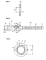
- FIG. 5 is a cross-sectional front view of a portion of the blind rivet in the embodiment of the present invention showing the swaged portion of the sleeve 11 in the rivet body 10.
- FIG. 6 is an enlarged cross-sectional view of the blind rivet from A-A in FIG. 5 .
- the mandrel 20 is inserted into the through hole 13 from the sleeve-side end portion 14 of the rivet body 10.
- the tip portion 27 of the mandrel is inserted first.
- the head 23 of the mandrel 20 makes contact with the sleeve-side end portion 14 and stops.
- the blind rivet in which the rivet body 10 and the mandrel 20 have been combined is pushed in at two locations on the sleeve 11 of the rivet body 10 on opposite ends radially using a swaging machine to form recessed portions 16.
- the outer diameter of the sleeve 11 in the direction perpendicular to the recessed portions 16 is made an expanded-diameter portion 17 whose outer diameter 11e is somewhat greater than the original outer diameter 11 d.
- the inner diameter 31 d of the center hole 31 in the washer 30 is somewhat smaller than the outer diameter 11 e of the expanded-diameter portion 17 which enlarges the sleeve 11 so that it becomes fixed when the washer 30 is pushed onto the expanded-diameter portion 17.
- the swaging is performed after the rivet body 10 has been combined with the mandrel 20.
- the swaging can be performed with a hard column-shaped component conforming to the inner diameter of the through hole 13 inserted into the through hole 13 of the rivet body 10. The mandrel 20 can be inserted afterwards.
- the recessed portions 16 are formed in the portion of the outer peripheral surface of the sleeve 11 in the rivet body 10 adjacent to the flange 12. Even if recessed portions 16 are not formed, the sleeve 11 can be pushed in at two locations on opposite sides radially to give the portion of the sleeve 11 an oval shape. This forms an expanded-diameter portion whose outer diameter is slightly greater than the inner diameter 31 d of the center hole 31 of the washer 30. The washer 30 can thus be fixed to the expanded-diameter portion.
- protrusions can be formed in a portion of the outer peripheral surface of the sleeve 11 in the rivet body 10 adjacent to the flange. These protrusions engage and secure the inner diameter of the washer 30.
- FIG. 7 is a cross-sectional front view of a portion of the embodiment of the present invention showing the washer 30 mounted on the blind rivet.
- FIG. 8 is an enlarged cross-sectional view of the blind rivet from B-B in FIG. 7 .
- the washer 30 is inserted over the sleeve 11, pushed into the expanded-diameter portion 17, and secured. This completes the blind rivet with washer in the embodiment of the present invention.
- FIG. 9 is a cross-sectional front view of a portion showing the blind rivet set in the mounted components 40, 41.
- the left side is the blind side
- the blind rivet is mounted from the right side.
- the mounting hole 43 in mounted component 40 is larger than the mounting hole 42 in mounted component 41.
- the inner diameter of the mounting hole 43 in mounted component 40 is greater than the outer diameter 12d of the flange 12.
- the mounted components 40, 41 cannot be fastened using a blind rivet of the prior art because the flange passes through the mounting hole 43 in mounted component 40.
- the embodiment of the present invention uses a washer 30 whose outer diameter is greater than the inner diameter of the mounting hole 43 in mounted component 40, mounted components 40 and 41 can be fastened.
- the mounted components 40, 41 are placed together so that the positions of the mounting hole 43 in mounted component 40 and the mounting hole 42 in mounted component 41 are aligned.
- the rivet body 10 and the mandrel 20 are assembled, and a washer 30 is mounted to obtain the blind rivet in FIG. 7 , which is inserted into the holes in the mounted components 40, 41 from the right side of FIG. 9 .
- the washer 30 mounted on the rivet body 10 makes contact with the peripheral surface of the mounting hole 43 in the mounted component 40.
- FIG. 10 is a cross-sectional front view of a portion of the intermediate stage in which mounted component 40 is fastened using the blind rivet. While holding the inclined portion 19 near the tip of the flange 12 in the rivet body 10 using the nose piece 50 of a fastening tool, the gripped portion 26 of the mandrel 20 is gripped with the gripping component 51 of the fastening tool and pulled. At this time, the head 23 of the mandrel 20 is pushed ogjnto the sleeve-side end portion 14 of the sleeve 11 in the rivet body 10 to form an expanded portion 18. The expanded portion 18 makes contact with the periphery of the mounting hole 42 in mounted component 41.
- FIG. 11 is a cross-sectional front view of a portion showing the mounted components 40, 41 fastened together by the blind rivet when the gripped portion 26 of the mandrel 20 is again pulled. While the inclined portion 19 of the flange 20 is pulled from the outer periphery by the nose piece 50, the flange 20 becomes deformed such that its outer diameter 12d is reduced to become the smaller outer diameter 12d'. At this time, the inner peripheral surface of the through hole 13 in a portion of the flange 20 is deformed such that its diameter becomes smaller than inner diameter 13d. This engages the engagement protrusions in the engagement portion 28 of the mandrel 20.
- the tip face of the nose piece 50 makes contact with the surface of the washer 30 and stops.
- the mounted components 40, 41 are interposed between the expanded-diameter portion 18 and the washer 30 of the blind rivet.
- the mandrel 20 is broken in the breakable portion 25, and the section from the breakable portion 25 to the head 23 remains in the fastened portion. Because the inner periphery of the flange 12 in the rivet body 10 is engaged with the engagement portion 28 of the mandrel 20, the portion of the mandrel 20 remaining in the blind rivet does not come off the blind rivet. Because the remaining portion of the mandrel 20 is fixed securely in the rivet body 10, high fastening force can be obtained. Afterwards, the nose piece 50 is withdrawn to the right in FIG. 11 , and the fastening operation is complete.
- the inner diameter of the mounting holes in the mounted components is usually smaller than the outer diameter 12d of the flange 12.
- the inner diameter of the mounting holes 43 is larger than the outer diameter 12d of the flange 12.
- a washer 30 is attached whose outer diameter is greater than the inner diameter of the mounting holes 43, the washer 30 makes contact with mounted component 40, and mounted components 40 and 41 can be fastened together.
- the inner diameter of the mounting holes in the mounted components is different, the mounted components can be fastened together if a washer with an outer diameter different from the inner diameters is used.
- mounting holes with various inner diameters can be accommodated by preparing washers with different outer diameters and combining one type of rivet body 10 and mandrel 20 with washers of varying outer diameters.
Abstract
Description
- The present invention relates to a blind rivet. More specifically, the present invention relates to a blind rivet and fastening method therefor in which mounted components with large mounting holes can be fastened together using a blind rivet with a washer.
- A well-known blind rivet contains a hollow metal rivet body composed of a sleeve and a flange at one end of the sleeve, and a metal mandrel whose stem extends from the flange of the sleeve and passes through the rivet body. This blind rivet is advantageously able to fasten together a plurality of panels by performing an operation on only one side. A flange is formed in one end of the rivet body of the blind rivet, and the rivet body has a cylindrical hollow sleeve extending from the flange. The mandrel in the blind rivet has in the end portion a head whose outer diameter is greater than the inner diameter of the sleeve, and a stem whose outer diameter is able to pass through the rivet body. The head of the mandrel is arranged adjacent to the end of the sleeve which is on the opposite side relative to the flange of the rivet body, and the stem of the mandrel is inserted into the through hole in the rivet body from the flange so as to extend out and complete the assembled blind rivet. The blind rivet is inserted into holes in mounted components such as panels with the head of the mandrel inserted first, and the flange on the sleeve makes contact with the area surrounding the hole in a mounted component. In this state, the flange on the sleeve is held with a fastening tool, and the stem of the mandrel is gripped and pulled strongly from the flange side of the rivet. This deforms one end of the sleeve in the blind rivet and expands the diameter. The mandrel breaks off in the slender breakable portion of the stem, and the panels or other mounted components are fastened between the flange on the rivet body and the expanded-diameter end of the sleeve.
- In the case of a blind rivet of the prior art, it is assumed that the outer diameter of the rivet body is greater than the inner diameter of the holes in the mounted components to be fastened. When the outer diameter of the flange on the rivet body is smaller than the inner diameter of the holes in the mounted components to be fastened, the panels or other mounted components cannot be fastened together. As a result, various rivet bodies with different flange diameters have to be prepared based on the hole diameter of the mounted components.
-
EP 0 286 244 A1 discloses a self-locking blind rivet. The blind rivet includes a rivet body having a shank and a rivet head at one end of the shank, a plug in which a spiral-shaped groove has been formed and which is connected by a bendable portion to an axial stem tail portion, and an axial stem having an end portion. When the blind rivet is fastened, material from the rivet head enters the spiral-shaped groove and becomes fastened. When the plug is turned relative to the rivet head, the fastened rivet can be released fairly easily. The known blind rivet cannot be fastened when the hole diameter in the panels to be fastened is greater than the flange diameter of the rivet body. - Therefore, there is demand for a blind rivet that can be used to fasten together panels even when the inner diameter of the holes in the panels to be fastened is greater than the outer diameter of the flange in the rivet body. There is also demand for a blind rivet that can fasten mounted components with different hole diameters.
- Thus, an object of the present invention is to provide a blind rivet that can fasten together mounted components such as panels even when the inner diameter of the mounting hole in the mounted components is greater than the outer diameter of the flange of the rivet body. Another object of the present invention is to provide a blind rivet able to fasten together mounted components with different hole diameters.
- According to the present invention this object is achieved by attaching a washer whose outer diameter is greater than the inner diameter of the holes in the fastened panels near the flange of the rivet body so that panels with large mounting holes can be fastened together.
- The first aspect of the present invention is a blind rivet for fastening together a plurality of mounted components with mounting holes, wherein the blind rivet comprises a rivet body having a hollow sleeve and a flange formed in one end of the sleeve, a through hole being formed so as to pass from the sleeve-side end portion to the flange-side end portion, a mandrel having a slender stem whose outer diameter is smaller than the inner diameter of the sleeve and whose length is greater than the length of the rivet body, and a head whose outer diameter is greater than the inner diameter of the sleeve, and a washer whose inner diameter is smaller than the outer diameter of the flange and whose outer diameter is greater than the outer diameter of the flange, and wherein the head of the mandrel is arranged adjacent to the sleeve-side end portion of the rivet body, the stem of the mandrel is configured so as to extend through the rivet body and from the flange-side end portion, and the washer is mounted near the flange on the outer periphery of the sleeve of the rivet body.
- A portion of the outer peripheral surface of the sleeve adjacent to the flange of the rivet body can be pushed in or pressed in to form a recessed portion, and the washer can be pushed into and mounted on the expanded-diameter portion of the sleeve in a portion other than the recessed portion.
- A recessed portion can be formed in two locations on the outer periphery of the sleeve on opposite sides circumferentially, and the portion between the recessed portions on the outer periphery of the sleeve can be the expanded-diameter portion with a larger outer diameter. Here, the inner periphery of the washer is fitted onto the expanded-diameter portion and secured.
- The recessed portion can be formed with the rivet body and mandrel already assembled. In this way, when the recessed portion is formed, the inner diameter of the sleeve of the rivet body is more difficult to deform, and the mandrel can be kept from becoming fixed to the rivet body or unable to be inserted into the rivet body.
- The outer peripheral surface of the sleeve adjacent to the flange of the rivet body can be pushed on both sides radially to form an oval-shaped cross-section, and the washer can be pushed onto and secured to the enlarged-diameter portion of the sleeve with a larger outer diameter. In this way, a portion with a large outer diameter can be easily formed in the sleeve to secure the inner periphery of the washer. A protrusion can be formed in an outer peripheral portion of the sleeve in the rivet body adjacent to the flange, and a washer can be pushed onto the protrusion and secured.
- Alternatively, the blind rivet can be inserted into the mounting holes of mounted components with the head of the mandrel in front so the surface of the washer contacts the periphery of the mounting holes of the mounted components when the mounted components are fastened, and the end portion of the sleeve can be pushed by the head to expand the diameter and fasten the mounted components between the expanded-diameter end portion of the sleeve and the washer when the flange of the rivet body is supported and the stem of the mandrel is pulled out from the flange end.
- In the blind rivet, the mandrel can be broken at the small diameter breakable portion of the stem and the section from the breakable portion to the side with the head remains when the mounted components are fastened.
- The second aspect of the present invention is a method for fastening together mounted components using a blind rivet, wherein a rivet body having a hollow sleeve, a flange formed in one end of the sleeve, and a through hole, a mandrel having a slender stem whose outer diameter is smaller than the inner diameter of the sleeve and whose length is greater than the rivet body, and a head whose outer diameter is greater than the inner diameter of the sleeve, and a washer whose inner diameter is smaller than the outer diameter of the flange and whose outer diameter is greater than the outer diameter of the flange are prepared, wherein the rivet body, the mandrel and the washer are combined to form a blind rivet, and wherein the blind rivet is inserted into the mounting holes of mounted components from the head of the mandrel and the surface of the washer contacts the periphery of the mounting holes of the mounted components when the mounted components are fastened, and the end portion of the sleeve is pushed by the head to expand the diameter and fasten the mounted components between the expanded-diameter end portion of the sleeve and the washer when the flange of the rivet body is supported and the stem of the mandrel is pulled out from the flange end.
- In this method, during the step in which the rivet body, mandrel and washer are combined to form a blind rivet, the mandrel can be inserted with the tip portion leading into the through hole from the sleeve-side end portion of the rivet body, the head of the mandrel contacting the sleeve-side end portion and stopping, a portion of the sleeve in the rivet body can be pushed in to form a recessed portion and an expanded-diameter portion in a position on the sleeve other than the recessed portion whose outer diameter is larger, and a washer can be pushed into the expanded-diameter portion from the head side of the mandrel and secured.
- In the present invention, a blind rivet is provided that can fasten together mounted components even when the inner diameter of the mounting hole in the mounted components is greater than the outer diameter of the flange of the rivet body. If combined with washers of different outer diameters, a blind rivet able to fasten together mounted components with different hole diameters can be provided.
- The present invention will become more fully understood from the detailed description and the accompanying drawings, wherein:
-
FIG. 1 is a cross-sectional front view of a portion of the blind rivet in an embodiment of the present invention, -
FIG. 2 is a cross-sectional front view of a portion of the rivet body in the blind rivet ofFIG. 1 , -
FIG. 3 is a front view of the mandrel in the blind rivet ofFIG. 1 , -
FIG. 4 is a cross-sectional view of the washer in the embodiment of the present invention, -
FIG. 5 is a cross-sectional front view of a portion of the blind rivet in the embodiment of the present invention showing the swaged portion of the sleeve in the rivet body, -
FIG. 6 is an enlarged cross-sectional view of the blind rivet from A-A inFIG. 5 , -
FIG. 7 is a cross-sectional front view of a portion of the embodiment of the present invention showing the washer mounted on the blind rivet, -
FIG. 8 is an enlarged cross-sectional view of the blind rivet from B-B inFIG. 7 , -
FIG. 9 is a cross-sectional front view of a portion showing the blind rivet inFIG. 7 inserted into the holes in the mounted components, -
FIG. 10 is a cross-sectional front view of a portion of the intermediate stage for fastening together mounted components using the blind rivet inFIG. 7 , and -
FIG. 11 is a cross-sectional front view of a portion showing the mounted components fastened together using the blind rivet inFIG. 7 . - The following is an explanation with reference to the figures of the blind rivet equipped with a washer in an embodiment of the present invention.
-
FIG. 1 is a cross-sectional front view of a portion of the blind rivet in an embodiment of the present invention. The blind rivet includes arivet body 10 and amandrel 20. Themandrel 20 is inserted from the sleeve-side end portion 14 of therivet body 10, and thehead 23 of themandrel 20 is arranged adjacent to the sleeve-side end portion 14 of therivet body 10. - The following is an explanation with reference to
FIG. 2 through FIG. 4 of therivet body 10,mandrel 20, and washer 30 constituting the blind rivet.FIG. 2 is a cross-sectional front view of a portion of therivet body 10 used in the blind rivet of the embodiment of the present invention. Therivet body 10 has acylindrical sleeve 11, and aflange 12 formed at one end of thesleeve 11 whose diameter is greater than that of thesleeve 11. The tip portion of theflange 12 has aninclined portion 19 whose outer diameter is reduced to a tapered shape, and end portion at the flange-side end portion 15. When the blind rivet is fastened, theinclined portion 19 is pushed by thenose piece 50 of the fastening tool from the outer periphery and reduced. - The opposite side of the
sleeve 11 from theflange 12 is the sleeve-side end portion 14. A throughhole 13 extends between the flange-side end portion 15 of therivet body 10 and the sleeve-side end portion 14. Theinner diameter 13d of thethrough hole 13 is large enough to allow thestem 21 of themandrel 20 to be inserted, but smaller than the outer diameter of thehead 23 of themandrel 20 so that thehead 23 makes contact with the sleeve-side end portion 14 and stops. Theouter diameter 11 d of thesleeve 11 is somewhat smaller than the diameter of the mounting holes in the components to be mounted but a size that allows it to pass through the mounting holes. Therivet body 10 can be made of a material softer than themandrel 20 such as aluminum or an aluminum alloy. It can also be made of the same material as themandrel 20 such as steel. -
FIG. 3 is a front view of themandrel 20 in the blind rivet of the embodiment of the present invention. Themandrel 20 is equipped with aslender stem 21 and ahead 23 on one end of thestem 21. Theouter diameter 23d of thehead 23 is greater than theinner diameter 13d of the throughhole 13 in therivet body 10. Theouter diameter 23d of thehead 23 is smaller than the inner diameter 42d of the mountingholes 42 in the mountedcomponents 40 so that it can pass through the mounting holes 42. Thestem 21 is column-shaped and has an outer diameter smaller than theinner diameter 13d of the throughhole 13 in therivet body 10 so that it can be inserted into the throughhole 13. The length of thestem 21 is greater than the length of the throughhole 13 of therivet body 10. When thestem 21 of themandrel 20 is inserted into the throughhole 13 in therivet body 10, the tip of thestem 21 protrudes from the flange-side end portion 15 of therivet body 10. - The
stem 21 of themandrel 20 includes from thehead 23, a column-shapedportion 24, anengagement portion 28, abreakable portion 25, a grippedportion 26, and atip portion 27. The column-shapedportion 24 is adjacent to thehead 23. The outer diameter of the column-shapedportion 24 is somewhat larger than theinner diameter 13d of the throughhole 13, and is forcibly inserted into the throughhole 13. This keeps the mandrel from coming out of the sleeve. Theengagement portion 28 is adjacent to the column-shapedportion 24. Two circumferential grooves are formed circumferentially at a given interval in theengagement portion 28, and an engagement protrusion is formed between the grooves. When the blind rivet is fastened, a portion of theflange 12 is pushed from the outer periphery and its inner diameter is reduced. The engagement protrusion engages the inner periphery of the throughhole 13 which has a smaller inner diameter, and a portion of the mandrel is kept from coming out of therivet body 10. - The
breakable portion 25, which has an outer diameter smaller than that of theengagement portion 28, is adjacent to theengagement portion 28. Thebreakable portion 25 is a portion accommodated in the throughhole 13 of therivet body 10 when the blind rivet is assembled. When thestem 21 of themandrel 20 is pulled out strongly using a fastening tool, thebreakable portion 25 breaks once a certain withdrawal force is exceeded. The grippedportion 26, which has a diameter greater than that of thebreakable portion 25, is adjacent to thebreakable portion 25. A plurality of engagement grooves are formed in the grippedportion 26 so that it does not slip when gripped by the fastening tool. Thetip portion 27 of thestem 21 has a slender tip. The tip is slender so that it can be more easily inserted into the fastening tool. Themandrel 20 is made of steel. -
FIG. 4 is a cross-sectional view of thewasher 30 used in the blind rivet of the embodiment of the present invention. Thewasher 30 is a disk-shaped component. Acenter hole 31 is opened in the center portion with a round cross-section viewed axially. Theinner diameter 31 d of thecenter hole 31 is somewhat smaller than theouter diameter 23d of thehead 23 of themandrel 20, and equal to or somewhat greater than theouter diameter 11 d of thesleeve 11. When themandrel 20 and therivet body 10 have been assembled, thewasher 30 can be inserted on thesleeve 11 of the blind rivet from thehead 23 side of themandrel 20. Theinner diameter 31 d of thecenter hole 31 is large enough to fix thewasher 30 to the outer periphery of thesleeve 11 when thesleeve 11 has been slightly deformed to form an expanded-diameter portion. - The following is an explanation with reference to
FIG. 5 through FIG. 8 of the steps performed to create the blind rivet with a washer in the embodiment of the present invention. Here, one end of thesleeve 11 on therivet body 10 of the blind rivet is pushed in and swaged, and thewasher 30 is pushed onto the portion with an external shape greater than the swaged portion of thesleeve 11.FIG. 5 is a cross-sectional front view of a portion of the blind rivet in the embodiment of the present invention showing the swaged portion of thesleeve 11 in therivet body 10.FIG. 6 is an enlarged cross-sectional view of the blind rivet from A-A inFIG. 5 . First, therivet body 10 and themandrel 20 are combined. Themandrel 20 is inserted into the throughhole 13 from the sleeve-side end portion 14 of therivet body 10. Thetip portion 27 of the mandrel is inserted first. Thehead 23 of themandrel 20 makes contact with the sleeve-side end portion 14 and stops. - Next, the blind rivet in which the
rivet body 10 and themandrel 20 have been combined is pushed in at two locations on thesleeve 11 of therivet body 10 on opposite ends radially using a swaging machine to form recessedportions 16. At this time, the outer diameter of thesleeve 11 in the direction perpendicular to the recessedportions 16 is made an expanded-diameter portion 17 whoseouter diameter 11e is somewhat greater than the originalouter diameter 11 d. Theinner diameter 31 d of thecenter hole 31 in thewasher 30 is somewhat smaller than theouter diameter 11 e of the expanded-diameter portion 17 which enlarges thesleeve 11 so that it becomes fixed when thewasher 30 is pushed onto the expanded-diameter portion 17. - Preferably, the swaging is performed after the
rivet body 10 has been combined with themandrel 20. In this way, when the recessedportions 16 are formed in therivet body 10, the inner peripheral surface of the throughhole 13 is supported by the stem of the mandrel so that the inner peripheral surface of the throughhole 13 is not deformed. Alternatively, the swaging can be performed with a hard column-shaped component conforming to the inner diameter of the throughhole 13 inserted into the throughhole 13 of therivet body 10. Themandrel 20 can be inserted afterwards. - In this embodiment, the recessed
portions 16 are formed in the portion of the outer peripheral surface of thesleeve 11 in therivet body 10 adjacent to theflange 12. Even if recessedportions 16 are not formed, thesleeve 11 can be pushed in at two locations on opposite sides radially to give the portion of thesleeve 11 an oval shape. This forms an expanded-diameter portion whose outer diameter is slightly greater than theinner diameter 31 d of thecenter hole 31 of thewasher 30. Thewasher 30 can thus be fixed to the expanded-diameter portion. Alternatively, protrusions can be formed in a portion of the outer peripheral surface of thesleeve 11 in therivet body 10 adjacent to the flange. These protrusions engage and secure the inner diameter of thewasher 30. -
FIG. 7 is a cross-sectional front view of a portion of the embodiment of the present invention showing thewasher 30 mounted on the blind rivet.FIG. 8 is an enlarged cross-sectional view of the blind rivet from B-B inFIG. 7 . Thewasher 30 is inserted over thesleeve 11, pushed into the expanded-diameter portion 17, and secured. This completes the blind rivet with washer in the embodiment of the present invention. - The following is an explanation with reference to
FIG. 9 through FIG. 11 of the operations performed to fasten together mountedcomponents FIG. 9 is a cross-sectional front view of a portion showing the blind rivet set in the mountedcomponents FIG. 9 , the left side is the blind side, and the blind rivet is mounted from the right side. - In
FIG. 9 , the mountinghole 43 in mountedcomponent 40 is larger than the mountinghole 42 in mountedcomponent 41. The inner diameter of the mountinghole 43 in mountedcomponent 40 is greater than theouter diameter 12d of theflange 12. In this case, the mountedcomponents hole 43 in mountedcomponent 40. Because the embodiment of the present invention uses awasher 30 whose outer diameter is greater than the inner diameter of the mountinghole 43 in mountedcomponent 40, mountedcomponents - The mounted
components hole 43 in mountedcomponent 40 and the mountinghole 42 in mountedcomponent 41 are aligned. Therivet body 10 and themandrel 20 are assembled, and awasher 30 is mounted to obtain the blind rivet inFIG. 7 , which is inserted into the holes in the mountedcomponents FIG. 9 . Thewasher 30 mounted on therivet body 10 makes contact with the peripheral surface of the mountinghole 43 in the mountedcomponent 40. -
FIG. 10 is a cross-sectional front view of a portion of the intermediate stage in which mountedcomponent 40 is fastened using the blind rivet. While holding theinclined portion 19 near the tip of theflange 12 in therivet body 10 using thenose piece 50 of a fastening tool, the grippedportion 26 of themandrel 20 is gripped with the grippingcomponent 51 of the fastening tool and pulled. At this time, thehead 23 of themandrel 20 is pushed ogjnto the sleeve-side end portion 14 of thesleeve 11 in therivet body 10 to form an expandedportion 18. The expandedportion 18 makes contact with the periphery of the mountinghole 42 in mountedcomponent 41. -
FIG. 11 is a cross-sectional front view of a portion showing the mountedcomponents portion 26 of themandrel 20 is again pulled. While theinclined portion 19 of theflange 20 is pulled from the outer periphery by thenose piece 50, theflange 20 becomes deformed such that itsouter diameter 12d is reduced to become the smallerouter diameter 12d'. At this time, the inner peripheral surface of the throughhole 13 in a portion of theflange 20 is deformed such that its diameter becomes smaller thaninner diameter 13d. This engages the engagement protrusions in theengagement portion 28 of themandrel 20. - When the tip face of the
nose piece 50 makes contact with the surface of thewasher 30 and stops. The mountedcomponents diameter portion 18 and thewasher 30 of the blind rivet. Afterwards, themandrel 20 is broken in thebreakable portion 25, and the section from thebreakable portion 25 to thehead 23 remains in the fastened portion. Because the inner periphery of theflange 12 in therivet body 10 is engaged with theengagement portion 28 of themandrel 20, the portion of themandrel 20 remaining in the blind rivet does not come off the blind rivet. Because the remaining portion of themandrel 20 is fixed securely in therivet body 10, high fastening force can be obtained. Afterwards, thenose piece 50 is withdrawn to the right inFIG. 11 , and the fastening operation is complete. - When mounted components are fastened together using a blind rivet, the inner diameter of the mounting holes in the mounted components is usually smaller than the
outer diameter 12d of theflange 12. In the embodiment of the present invention, the inner diameter of the mounting holes 43 is larger than theouter diameter 12d of theflange 12. However, because awasher 30 is attached whose outer diameter is greater than the inner diameter of the mountingholes 43, thewasher 30 makes contact with mountedcomponent 40, and mountedcomponents rivet body 10 andmandrel 20 with washers of varying outer diameters.
Claims (9)
- A blind rivet for fastening together a plurality of mounted components with mounting holes,
wherein the blind rivet comprises a rivet body (10) having a hollow sleeve (11) and a flange (12) formed in one end of the sleeve (11), a through hole (13) being formed so as to pass from a sleeve-side end portion (14) to a flange-side end portion (15),
a mandrel (20) having a slender stem (21) whose outer diameter is smaller than the inner diameter (13d) of the sleeve (11) and whose length is greater than the length of the rivet body (10), and a head (23) whose outer diameter (23d) is greater than the inner diameter (13d) of the sleeve (11), characterised by
a washer (30) whose inner diameter (31 d) is smaller than the outer diameter (12d) of the flange (12) and whose outer diameter is greater than the outer diameter (12d) of the flange (12), and
wherein the head (23) of the mandrel (20) is arranged adjacent to the sleeve-side end portion (14) of the rivet body (10), the stem (21) of the mandrel (20) is configured so as to extend through the rivet body (10) and from the flange-side end portion (15), and the washer (30) is mounted near the flange (12) on the outer periphery of the sleeve (11) of the rivet body (10). - The blind rivet of claim 1, wherein a portion of the outer peripheral surface of the sleeve (11) adjacent to the flange (12) of the rivet body (10) is swaged to form a recessed portion (16), and an expanded-diameter portion (17), and wherein the washer (30) is pushed onto and mounted on the expanded-diameter portion (17) of the sleeve (11) in a portion other than the recessed portion (16).
- The blind rivet of claim 2, wherein recessed portions (16) are formed in two locations on the outer periphery of the sleeve (11) on opposite sides circumferentially, and wherein the portion between the recessed portions (16) on the outer periphery of the sleeve is the expanded-diameter portion (17) with a larger outer diameter.
- The blind rivet of claim 2, wherein the recessed portion (16) is formed with the rivet body (10) and mandrel (20) assembled.
- The blind rivet of claim 1, wherein the outer peripheral surface of the sleeve (11) adjacent to the flange (12) of the rivet body (10) is pushed on both sides radially to form an oval-shaped cross-section, and wherein the washer (30) is pushed on and secured to the enlarged-diameter portion of the oval-shaped cross-section of the sleeve (11).
- The blind rivet in any one of claims 1 through 5, wherein the blind rivet is inserted into mounting holes (42, 43) of mounted components (41, 40) with the head (23) of the mandrel (20) in front and the surface of the washer (30) contacts the periphery of the mounting hole (43) of the adjacent mounted component (40) when the mounted components (41, 40) are fastened, and wherein the sleeve-side end portion (14) of the sleeve (11) is pushed by the head (23) to expand the diameter of the sleeve (11) to form an expanded-diameter end portion (18) and to fasten the mounted components (41, 40) between the expanded-diameter end portion (18) of the sleeve (11) and the washer (30) when the flange (12) of the rivet body (10) is supported and the stem (21) of the mandrel (20) is pulled out from the flange end (15).
- The blind rivet of claim 6, wherein the mandrel (20) is broken at a small diameter breakable portion (25) of the stem (21) and the section extending from the breakable portion (25) to the head (23) remains in the rivet body (10) when the mounted components (41, 40) are fastened.
- A method for fastening together mounted components (41, 40) using a blind rivet, wherein
a rivet body (10) having a hollow sleeve (11), a flange (12) formed in one end of the sleeve (11), and a through hole (13),
a mandrel (20) having a slender stem (21) whose outer diameter is smaller than the inner diameter of the sleeve (11) and whose length is greater than the length of the rivet body (10), and a head (23) whose outer diameter is greater than the inner diameter of the sleeve (11), characterized in that
a washer (30) is prepared having an inner diameter that is smaller than the outer diameter of the flange (12) and outer diameter that is greater than the outer diameter of the flange (12),
wherein the rivet body (10), the mandrel (20) and the washer (30) are combined to form a blind rivet, and
wherein the blind rivet is inserted into the mounting holes (42, 43) of mounted components (41, 40) with the head (23) of the mandrel (20) in front and the surface of the washer (30) contacts the periphery of the mounting hole (43) of the adjacent mounted component (40) when the mounted components (41, 40) are fastened, and the sleeve-side end portion (14) of the sleeve (11) is pushed by the head (23) to expand the diameter of the sleeve (11) to form an expanded-diameter end portion (18) and to fasten the mounted components (41, 40) between the expanded-diameter end portion (18) and the washer (30) when the flange (12) of the rivet body (10) is supported and the stem (21) of the mandrel (20) is pulled out from the flange end (15). - The method of claim 8, wherein, during the step in which the rivet body (10), mandrel (20) and washer (30) are combined to form a blind rivet, the mandrel (20) is inserted with the tip portion (27) in front into the through hole (13) from the sleeve-side end portion (14) of the rivet body (10), the head (23) of the mandrel (20) contacts the sleeve-side end portion (14) and stops, a portion of the sleeve (11) in the rivet body (10) is pushed in to form a recessed portion (16) and, in a position on the sleeve (11) other than the recessed portion (16), an expanded-diameter portion (17) having a larger outer diameter, and a washer (30) is pushed onto the expanded-diameter portion (17) from the head side end of the mandrel (20) and secured.
Applications Claiming Priority (1)
| Application Number | Priority Date | Filing Date | Title |
|---|---|---|---|
| JP2010255623A JP5649921B2 (en) | 2010-11-16 | 2010-11-16 | Blind rivet and its fastening method |
Publications (2)
| Publication Number | Publication Date |
|---|---|
| EP2453142A1 true EP2453142A1 (en) | 2012-05-16 |
| EP2453142B1 EP2453142B1 (en) | 2016-08-24 |
Family
ID=45093353
Family Applications (1)
| Application Number | Title | Priority Date | Filing Date |
|---|---|---|---|
| EP11189089.3A Active EP2453142B1 (en) | 2010-11-16 | 2011-11-15 | A blind rivet and fastening method thereof |
Country Status (3)
| Country | Link |
|---|---|
| US (1) | US9011057B2 (en) |
| EP (1) | EP2453142B1 (en) |
| JP (1) | JP5649921B2 (en) |
Cited By (1)
| Publication number | Priority date | Publication date | Assignee | Title |
|---|---|---|---|---|
| CN105197248A (en) * | 2014-06-27 | 2015-12-30 | 波音公司 | Method And Apparatus For Fuel Tank Spark Containment |
Families Citing this family (2)
| Publication number | Priority date | Publication date | Assignee | Title |
|---|---|---|---|---|
| KR200489466Y1 (en) * | 2017-03-31 | 2019-10-01 | 김준영 | Rivet for preventing scratch |
| DE102017115248B4 (en) * | 2017-07-07 | 2020-03-12 | Saf-Holland Gmbh | System for fixing a pivot bolt to a vehicle frame, vehicle frame for connecting a pivot bolt and method for mounting a pivot bolt on a vehicle frame |
Citations (5)
| Publication number | Priority date | Publication date | Assignee | Title |
|---|---|---|---|---|
| GB1000561A (en) * | 1962-01-17 | 1965-08-04 | Pierre Launay | Improvements in fixation devices comprising a screw and a ring |
| GB2081833A (en) * | 1980-07-23 | 1982-02-24 | Larsson Sven Bertil | Extractable blind rivets |
| US4585382A (en) * | 1983-12-01 | 1986-04-29 | Usm Corporation | Easily removable rivet with tab |
| EP0286244A1 (en) | 1987-03-19 | 1988-10-12 | Avdel Systems Limited | Self-plugging blind rivet |
| DE102005003770B3 (en) * | 2005-01-27 | 2006-07-06 | Knorr-Bremse Systeme für Nutzfahrzeuge GmbH | Brake e.g. disc brake, connection for commercial vehicle, has form fit units to connect brake caliper of brake with axle connector of axle for torque transmission from brake to axle and lying in recesses of connector and caliper |
Family Cites Families (20)
| Publication number | Priority date | Publication date | Assignee | Title |
|---|---|---|---|---|
| USRE22792E (en) | 1932-08-03 | 1946-09-17 | Riveted structure and method of | |
| GB425469A (en) | 1933-07-20 | 1935-03-04 | Louis Charles Huck | Improved method of rivetting and an improved rivet for use with such method |
| US2114493A (en) * | 1935-05-14 | 1938-04-19 | Huxon Holding Corp | Rivet and rivet setting |
| US3215024A (en) | 1957-07-11 | 1965-11-02 | Huck Mfg Co | Fastener |
| GB943980A (en) * | 1961-10-21 | 1963-12-11 | George Goodman Ltd | Improved fastening device |
| US3298270A (en) * | 1962-01-17 | 1967-01-17 | Launay Pierre | Fixation device comprising a screw and a ring |
| JPS4820821Y1 (en) * | 1968-01-10 | 1973-06-16 | ||
| CA1096666A (en) * | 1976-12-10 | 1981-03-03 | Dieter Mauer | Fastening |
| US4509243A (en) * | 1982-02-08 | 1985-04-09 | Gas Research Institute | Blind side sealer apparatus and method |
| US4687217A (en) * | 1985-01-22 | 1987-08-18 | Stewart Derrel N | Shield for automotive vehicle |
| JPS61223316A (en) * | 1985-03-29 | 1986-10-03 | 昭和飛行機工業株式会社 | Detent device for blind nut |
| JPS6387312U (en) * | 1986-11-28 | 1988-06-07 | ||
| JPH03121205U (en) * | 1990-03-23 | 1991-12-12 | ||
| JPH0563035U (en) * | 1992-01-31 | 1993-08-20 | マルコン電子株式会社 | Aluminum electrolytic capacitor |
| JP2505089B2 (en) * | 1992-02-20 | 1996-06-05 | 勝美 池田 | Fastening member, fastening machine element set, method of joining fastening machine elements |
| US5762456A (en) * | 1996-05-17 | 1998-06-09 | Asar Group, Inc. | Self tapping blind setting bolt rivet assembly |
| US6092968A (en) * | 1998-05-29 | 2000-07-25 | Mcgard, Inc. | Fastener structure |
| US7699570B2 (en) * | 2002-06-07 | 2010-04-20 | Illinois Tool Works Inc. | Grommet connector |
| JP4651117B2 (en) * | 2006-11-07 | 2011-03-16 | 株式会社ユニオン精密 | Fastening parts and equipment having a fastening structure |
| US7954517B1 (en) * | 2009-10-29 | 2011-06-07 | Vittorio Marinelli | Rivet plumbing repair apparatus and method |
-
2010
- 2010-11-16 JP JP2010255623A patent/JP5649921B2/en active Active
-
2011
- 2011-11-14 US US13/295,395 patent/US9011057B2/en active Active
- 2011-11-15 EP EP11189089.3A patent/EP2453142B1/en active Active
Patent Citations (5)
| Publication number | Priority date | Publication date | Assignee | Title |
|---|---|---|---|---|
| GB1000561A (en) * | 1962-01-17 | 1965-08-04 | Pierre Launay | Improvements in fixation devices comprising a screw and a ring |
| GB2081833A (en) * | 1980-07-23 | 1982-02-24 | Larsson Sven Bertil | Extractable blind rivets |
| US4585382A (en) * | 1983-12-01 | 1986-04-29 | Usm Corporation | Easily removable rivet with tab |
| EP0286244A1 (en) | 1987-03-19 | 1988-10-12 | Avdel Systems Limited | Self-plugging blind rivet |
| DE102005003770B3 (en) * | 2005-01-27 | 2006-07-06 | Knorr-Bremse Systeme für Nutzfahrzeuge GmbH | Brake e.g. disc brake, connection for commercial vehicle, has form fit units to connect brake caliper of brake with axle connector of axle for torque transmission from brake to axle and lying in recesses of connector and caliper |
Cited By (4)
| Publication number | Priority date | Publication date | Assignee | Title |
|---|---|---|---|---|
| CN105197248A (en) * | 2014-06-27 | 2015-12-30 | 波音公司 | Method And Apparatus For Fuel Tank Spark Containment |
| EP2960159A1 (en) * | 2014-06-27 | 2015-12-30 | The Boeing Company | Method and apparatus for fuel tank spark containment |
| US9551373B2 (en) | 2014-06-27 | 2017-01-24 | The Boeing Company | Apparatus for fuel tank spark containment |
| US10393161B2 (en) | 2014-06-27 | 2019-08-27 | The Boeing Company | Method for fuel tank spark containment |
Also Published As
| Publication number | Publication date |
|---|---|
| US9011057B2 (en) | 2015-04-21 |
| EP2453142B1 (en) | 2016-08-24 |
| JP2012107663A (en) | 2012-06-07 |
| JP5649921B2 (en) | 2015-01-07 |
| US20120117786A1 (en) | 2012-05-17 |
Similar Documents
| Publication | Publication Date | Title |
|---|---|---|
| JP5711593B2 (en) | Blind rivet and its fastening method | |
| EP2337959B1 (en) | Blind fastener | |
| US7156596B2 (en) | Blind rivet and fastening method | |
| JP5782106B2 (en) | fastener | |
| JP2005514566A5 (en) | ||
| US20170218996A1 (en) | Fastening structure and fastening method | |
| JP2011069442A (en) | Plastic blind rivet | |
| EP2453142A1 (en) | A blind rivet and fastening method thereof | |
| US9573187B2 (en) | Blind, bulbing, tacking rivet and method of installation | |
| US8430613B2 (en) | Blind rivet | |
| EP2436935A1 (en) | A blind rivet and fastening method thereof | |
| JP2009041699A (en) | Blind rivet | |
| JPH07208423A (en) | Plastic made blind rivet | |
| CA2900081C (en) | Blind, bulbing, tacking rivet and method of installation | |
| JP2008255687A (en) | Anchor for concrete | |
| JP2012189124A (en) | Blind rivet and fastening method thereof | |
| JP2006057671A (en) | Blind rivet | |
| JP6131363B1 (en) | Rivet fastener and rivet fastening method | |
| JP2010144806A (en) | Fastening member and its mounting method |
Legal Events
| Date | Code | Title | Description |
|---|---|---|---|
| PUAI | Public reference made under article 153(3) epc to a published international application that has entered the european phase |
Free format text: ORIGINAL CODE: 0009012 |
|
| AK | Designated contracting states |
Kind code of ref document: A1 Designated state(s): AL AT BE BG CH CY CZ DE DK EE ES FI FR GB GR HR HU IE IS IT LI LT LU LV MC MK MT NL NO PL PT RO RS SE SI SK SM TR |
|
| AX | Request for extension of the european patent |
Extension state: BA ME |
|
| 17P | Request for examination filed |
Effective date: 20121023 |
|
| GRAP | Despatch of communication of intention to grant a patent |
Free format text: ORIGINAL CODE: EPIDOSNIGR1 |
|
| RAP1 | Party data changed (applicant data changed or rights of an application transferred) |
Owner name: NEWFREY LLC |
|
| INTG | Intention to grant announced |
Effective date: 20160419 |
|
| GRAS | Grant fee paid |
Free format text: ORIGINAL CODE: EPIDOSNIGR3 |
|
| GRAA | (expected) grant |
Free format text: ORIGINAL CODE: 0009210 |
|
| AK | Designated contracting states |
Kind code of ref document: B1 Designated state(s): AL AT BE BG CH CY CZ DE DK EE ES FI FR GB GR HR HU IE IS IT LI LT LU LV MC MK MT NL NO PL PT RO RS SE SI SK SM TR |
|
| REG | Reference to a national code |
Ref country code: GB Ref legal event code: FG4D |
|
| REG | Reference to a national code |
Ref country code: CH Ref legal event code: EP |
|
| REG | Reference to a national code |
Ref country code: AT Ref legal event code: REF Ref document number: 823385 Country of ref document: AT Kind code of ref document: T Effective date: 20160915 |
|
| REG | Reference to a national code |
Ref country code: IE Ref legal event code: FG4D |
|
| REG | Reference to a national code |
Ref country code: DE Ref legal event code: R096 Ref document number: 602011029560 Country of ref document: DE |
|
| REG | Reference to a national code |
Ref country code: FR Ref legal event code: PLFP Year of fee payment: 6 |
|
| REG | Reference to a national code |
Ref country code: LT Ref legal event code: MG4D |
|
| REG | Reference to a national code |
Ref country code: NL Ref legal event code: MP Effective date: 20160824 |
|
| REG | Reference to a national code |
Ref country code: AT Ref legal event code: MK05 Ref document number: 823385 Country of ref document: AT Kind code of ref document: T Effective date: 20160824 |
|
| PG25 | Lapsed in a contracting state [announced via postgrant information from national office to epo] |
Ref country code: HR Free format text: LAPSE BECAUSE OF FAILURE TO SUBMIT A TRANSLATION OF THE DESCRIPTION OR TO PAY THE FEE WITHIN THE PRESCRIBED TIME-LIMIT Effective date: 20160824 Ref country code: RS Free format text: LAPSE BECAUSE OF FAILURE TO SUBMIT A TRANSLATION OF THE DESCRIPTION OR TO PAY THE FEE WITHIN THE PRESCRIBED TIME-LIMIT Effective date: 20160824 Ref country code: NO Free format text: LAPSE BECAUSE OF FAILURE TO SUBMIT A TRANSLATION OF THE DESCRIPTION OR TO PAY THE FEE WITHIN THE PRESCRIBED TIME-LIMIT Effective date: 20161124 Ref country code: IT Free format text: LAPSE BECAUSE OF FAILURE TO SUBMIT A TRANSLATION OF THE DESCRIPTION OR TO PAY THE FEE WITHIN THE PRESCRIBED TIME-LIMIT Effective date: 20160824 Ref country code: NL Free format text: LAPSE BECAUSE OF FAILURE TO SUBMIT A TRANSLATION OF THE DESCRIPTION OR TO PAY THE FEE WITHIN THE PRESCRIBED TIME-LIMIT Effective date: 20160824 Ref country code: FI Free format text: LAPSE BECAUSE OF FAILURE TO SUBMIT A TRANSLATION OF THE DESCRIPTION OR TO PAY THE FEE WITHIN THE PRESCRIBED TIME-LIMIT Effective date: 20160824 Ref country code: LT Free format text: LAPSE BECAUSE OF FAILURE TO SUBMIT A TRANSLATION OF THE DESCRIPTION OR TO PAY THE FEE WITHIN THE PRESCRIBED TIME-LIMIT Effective date: 20160824 |
|
| PG25 | Lapsed in a contracting state [announced via postgrant information from national office to epo] |
Ref country code: LV Free format text: LAPSE BECAUSE OF FAILURE TO SUBMIT A TRANSLATION OF THE DESCRIPTION OR TO PAY THE FEE WITHIN THE PRESCRIBED TIME-LIMIT Effective date: 20160824 Ref country code: ES Free format text: LAPSE BECAUSE OF FAILURE TO SUBMIT A TRANSLATION OF THE DESCRIPTION OR TO PAY THE FEE WITHIN THE PRESCRIBED TIME-LIMIT Effective date: 20160824 Ref country code: SE Free format text: LAPSE BECAUSE OF FAILURE TO SUBMIT A TRANSLATION OF THE DESCRIPTION OR TO PAY THE FEE WITHIN THE PRESCRIBED TIME-LIMIT Effective date: 20160824 Ref country code: AT Free format text: LAPSE BECAUSE OF FAILURE TO SUBMIT A TRANSLATION OF THE DESCRIPTION OR TO PAY THE FEE WITHIN THE PRESCRIBED TIME-LIMIT Effective date: 20160824 Ref country code: GR Free format text: LAPSE BECAUSE OF FAILURE TO SUBMIT A TRANSLATION OF THE DESCRIPTION OR TO PAY THE FEE WITHIN THE PRESCRIBED TIME-LIMIT Effective date: 20161125 Ref country code: PT Free format text: LAPSE BECAUSE OF FAILURE TO SUBMIT A TRANSLATION OF THE DESCRIPTION OR TO PAY THE FEE WITHIN THE PRESCRIBED TIME-LIMIT Effective date: 20161226 Ref country code: BE Free format text: LAPSE BECAUSE OF NON-PAYMENT OF DUE FEES Effective date: 20161130 |
|
| PG25 | Lapsed in a contracting state [announced via postgrant information from national office to epo] |
Ref country code: EE Free format text: LAPSE BECAUSE OF FAILURE TO SUBMIT A TRANSLATION OF THE DESCRIPTION OR TO PAY THE FEE WITHIN THE PRESCRIBED TIME-LIMIT Effective date: 20160824 Ref country code: RO Free format text: LAPSE BECAUSE OF FAILURE TO SUBMIT A TRANSLATION OF THE DESCRIPTION OR TO PAY THE FEE WITHIN THE PRESCRIBED TIME-LIMIT Effective date: 20160824 |
|
| REG | Reference to a national code |
Ref country code: DE Ref legal event code: R097 Ref document number: 602011029560 Country of ref document: DE |
|
| PG25 | Lapsed in a contracting state [announced via postgrant information from national office to epo] |
Ref country code: CZ Free format text: LAPSE BECAUSE OF FAILURE TO SUBMIT A TRANSLATION OF THE DESCRIPTION OR TO PAY THE FEE WITHIN THE PRESCRIBED TIME-LIMIT Effective date: 20160824 Ref country code: SM Free format text: LAPSE BECAUSE OF FAILURE TO SUBMIT A TRANSLATION OF THE DESCRIPTION OR TO PAY THE FEE WITHIN THE PRESCRIBED TIME-LIMIT Effective date: 20160824 Ref country code: BG Free format text: LAPSE BECAUSE OF FAILURE TO SUBMIT A TRANSLATION OF THE DESCRIPTION OR TO PAY THE FEE WITHIN THE PRESCRIBED TIME-LIMIT Effective date: 20161124 Ref country code: BE Free format text: LAPSE BECAUSE OF FAILURE TO SUBMIT A TRANSLATION OF THE DESCRIPTION OR TO PAY THE FEE WITHIN THE PRESCRIBED TIME-LIMIT Effective date: 20160824 Ref country code: PL Free format text: LAPSE BECAUSE OF FAILURE TO SUBMIT A TRANSLATION OF THE DESCRIPTION OR TO PAY THE FEE WITHIN THE PRESCRIBED TIME-LIMIT Effective date: 20160824 Ref country code: SK Free format text: LAPSE BECAUSE OF FAILURE TO SUBMIT A TRANSLATION OF THE DESCRIPTION OR TO PAY THE FEE WITHIN THE PRESCRIBED TIME-LIMIT Effective date: 20160824 Ref country code: DK Free format text: LAPSE BECAUSE OF FAILURE TO SUBMIT A TRANSLATION OF THE DESCRIPTION OR TO PAY THE FEE WITHIN THE PRESCRIBED TIME-LIMIT Effective date: 20160824 |
|
| PLBE | No opposition filed within time limit |
Free format text: ORIGINAL CODE: 0009261 |
|
| REG | Reference to a national code |
Ref country code: CH Ref legal event code: PL |
|
| STAA | Information on the status of an ep patent application or granted ep patent |
Free format text: STATUS: NO OPPOSITION FILED WITHIN TIME LIMIT |
|
| PG25 | Lapsed in a contracting state [announced via postgrant information from national office to epo] |
Ref country code: LI Free format text: LAPSE BECAUSE OF NON-PAYMENT OF DUE FEES Effective date: 20161130 Ref country code: CH Free format text: LAPSE BECAUSE OF NON-PAYMENT OF DUE FEES Effective date: 20161130 |
|
| 26N | No opposition filed |
Effective date: 20170526 |
|
| REG | Reference to a national code |
Ref country code: IE Ref legal event code: MM4A |
|
| PG25 | Lapsed in a contracting state [announced via postgrant information from national office to epo] |
Ref country code: SI Free format text: LAPSE BECAUSE OF FAILURE TO SUBMIT A TRANSLATION OF THE DESCRIPTION OR TO PAY THE FEE WITHIN THE PRESCRIBED TIME-LIMIT Effective date: 20160824 |
|
| PG25 | Lapsed in a contracting state [announced via postgrant information from national office to epo] |
Ref country code: LU Free format text: LAPSE BECAUSE OF NON-PAYMENT OF DUE FEES Effective date: 20161130 |
|
| REG | Reference to a national code |
Ref country code: FR Ref legal event code: PLFP Year of fee payment: 7 |
|
| PG25 | Lapsed in a contracting state [announced via postgrant information from national office to epo] |
Ref country code: IE Free format text: LAPSE BECAUSE OF NON-PAYMENT OF DUE FEES Effective date: 20161115 |
|
| PGFP | Annual fee paid to national office [announced via postgrant information from national office to epo] |
Ref country code: DE Payment date: 20171108 Year of fee payment: 7 |
|
| PG25 | Lapsed in a contracting state [announced via postgrant information from national office to epo] |
Ref country code: CY Free format text: LAPSE BECAUSE OF FAILURE TO SUBMIT A TRANSLATION OF THE DESCRIPTION OR TO PAY THE FEE WITHIN THE PRESCRIBED TIME-LIMIT Effective date: 20160824 Ref country code: HU Free format text: LAPSE BECAUSE OF FAILURE TO SUBMIT A TRANSLATION OF THE DESCRIPTION OR TO PAY THE FEE WITHIN THE PRESCRIBED TIME-LIMIT; INVALID AB INITIO Effective date: 20111115 |
|
| PG25 | Lapsed in a contracting state [announced via postgrant information from national office to epo] |
Ref country code: MK Free format text: LAPSE BECAUSE OF FAILURE TO SUBMIT A TRANSLATION OF THE DESCRIPTION OR TO PAY THE FEE WITHIN THE PRESCRIBED TIME-LIMIT Effective date: 20160824 Ref country code: MC Free format text: LAPSE BECAUSE OF FAILURE TO SUBMIT A TRANSLATION OF THE DESCRIPTION OR TO PAY THE FEE WITHIN THE PRESCRIBED TIME-LIMIT Effective date: 20160824 Ref country code: IS Free format text: LAPSE BECAUSE OF FAILURE TO SUBMIT A TRANSLATION OF THE DESCRIPTION OR TO PAY THE FEE WITHIN THE PRESCRIBED TIME-LIMIT Effective date: 20160824 Ref country code: TR Free format text: LAPSE BECAUSE OF FAILURE TO SUBMIT A TRANSLATION OF THE DESCRIPTION OR TO PAY THE FEE WITHIN THE PRESCRIBED TIME-LIMIT Effective date: 20160824 |
|
| PG25 | Lapsed in a contracting state [announced via postgrant information from national office to epo] |
Ref country code: MT Free format text: LAPSE BECAUSE OF NON-PAYMENT OF DUE FEES Effective date: 20161115 |
|
| REG | Reference to a national code |
Ref country code: FR Ref legal event code: PLFP Year of fee payment: 8 |
|
| PG25 | Lapsed in a contracting state [announced via postgrant information from national office to epo] |
Ref country code: AL Free format text: LAPSE BECAUSE OF FAILURE TO SUBMIT A TRANSLATION OF THE DESCRIPTION OR TO PAY THE FEE WITHIN THE PRESCRIBED TIME-LIMIT Effective date: 20160824 |
|
| REG | Reference to a national code |
Ref country code: DE Ref legal event code: R119 Ref document number: 602011029560 Country of ref document: DE |
|
| PG25 | Lapsed in a contracting state [announced via postgrant information from national office to epo] |
Ref country code: DE Free format text: LAPSE BECAUSE OF NON-PAYMENT OF DUE FEES Effective date: 20190601 |
|
| PGFP | Annual fee paid to national office [announced via postgrant information from national office to epo] |
Ref country code: GB Payment date: 20230921 Year of fee payment: 13 |
|
| PGFP | Annual fee paid to national office [announced via postgrant information from national office to epo] |
Ref country code: FR Payment date: 20230911 Year of fee payment: 13 |