JP2012105974A - Toilet facility unit - Google Patents

Toilet facility unit Download PDF

Info

Publication number
JP2012105974A
JP2012105974A JP2011235350A JP2011235350A JP2012105974A JP 2012105974 A JP2012105974 A JP 2012105974A JP 2011235350 A JP2011235350 A JP 2011235350A JP 2011235350 A JP2011235350 A JP 2011235350A JP 2012105974 A JP2012105974 A JP 2012105974A
Authority
JP
Japan
Prior art keywords
toilet
urine
stool
storage tank
box
Prior art date
Legal status (The legal status is an assumption and is not a legal conclusion. Google has not performed a legal analysis and makes no representation as to the accuracy of the status listed.)
Pending
Application number
JP2011235350A
Other languages
Japanese (ja)
Inventor
Sogo Kato
宗▲悟▼ 加藤
Current Assignee (The listed assignees may be inaccurate. Google has not performed a legal analysis and makes no representation or warranty as to the accuracy of the list.)
Individual
Original Assignee
Individual
Priority date (The priority date is an assumption and is not a legal conclusion. Google has not performed a legal analysis and makes no representation as to the accuracy of the date listed.)
Filing date
Publication date
Application filed by Individual filed Critical Individual
Priority to JP2011235350A priority Critical patent/JP2012105974A/en
Publication of JP2012105974A publication Critical patent/JP2012105974A/en
Pending legal-status Critical Current

Links

Images

Landscapes

  • Non-Flushing Toilets (AREA)

Abstract

PROBLEM TO BE SOLVED: To provide a toilet facility unit that can be easily installed as temporary toilet facilities in a time of emergency, thus improving convenience for users.SOLUTION: The toilet facility unit 10 includes: an underground storage tank provided with an accommodation space embedded in the ground; and a toilet facility assembly 70 that is accommodated in the underground storage tank in an assembled state, and is taken out, when used, from the underground storage tank to make temporary toilets 20 and temporary urinals 30.

Description

本発明は、トイレユニットに関する。   The present invention relates to a toilet unit.

都市部において発生した震災により建物の崩壊や生活基盤を支えるライフラインの破壊が招かれると、被災者の生活は著しく不便なものとなる。特に、水道の断水や、下水道の破壊に伴い水洗トイレが使用不可能な状態に陥ると、復旧までの間における被災者の生活は極めて困窮したものとなる。このため、簡易式の仮設トイレを避難場所や公園等に設置するなどして迅速な対応を行うことが望まれる。しかしながら、現在用いられている一般的な仮設トイレには、搬送面や運用面において以下のような課題がある。   If an earthquake disaster occurs in an urban area that causes the collapse of buildings or the lifeline that supports the living infrastructure, the lives of the victims will be significantly inconvenient. In particular, if the flush toilet becomes unusable due to water supply interruption or sewer destruction, the lives of the victims until the restoration will be extremely difficult. For this reason, it is desirable to perform a quick response by installing a simple temporary toilet in an evacuation site or a park. However, a general temporary toilet currently used has the following problems in terms of transportation and operation.

第一に、建設現場やイベント会場等に設置される一般的な仮設トイレは、予め組み立てられた状態で車両等を利用して搬送される。このため、震災によって交通インフラが破壊されるような場合、避難場所への搬送に多大な労力および時間を費やすことになる。第二に、被災状況下ではその設置場所が左右されるため、設置箇所を予め計画的に選定しておくことができない。このため、設置場所に関する被災者への情報伝達性が悪い。第三に、一般的な仮設トイレは男女共有のものを1個単位で設置するものであるため、便槽の容積が比較的小さい。より多くの被災者に対応するためには、設置数を増加させることが必要であり、仮設トイレを設置する地上部分に広大な設置面積を確保することが必要になる。また、便槽の容積が小さいため、排泄物を汲み出す回数や排泄物の搬送回数が増加し、多大な手間を費やすことになる。   First, a general temporary toilet installed at a construction site or an event site is transported using a vehicle or the like in a preassembled state. For this reason, when a traffic infrastructure is destroyed by an earthquake disaster, much labor and time will be spent on the transportation to an evacuation site. Second, since the installation location depends on the disaster situation, the installation location cannot be selected in advance in a planned manner. For this reason, the information transmission nature to the victim about an installation place is bad. Thirdly, a general temporary toilet is a unit that is shared by men and women in units of one, so the volume of the toilet is relatively small. In order to cope with more victims, it is necessary to increase the number of installations, and it is necessary to secure a vast installation area on the ground part where temporary toilets are installed. Moreover, since the volume of the toilet bowl is small, the number of times of excretion excretion and the number of excretion transport increases, and a great deal of time is spent.

これらの問題の解決にあたり、地下に埋設させた便槽、および便槽内に折り畳んだ状態で収容させることが可能なトイレ壁組立体を備えるトイレ設備が提案されている(特許文献1を参照)。   In order to solve these problems, a toilet facility including a toilet tub buried underground and a toilet wall assembly that can be accommodated in a folded state in the toilet tub has been proposed (see Patent Document 1). .

特開2007−186921号公報JP 2007-186922 A

特許文献1に記載されたトイレ設備にあっては、仮設トイレや排泄物を搬送させるための搬送作業に伴う利便性の低下や、設置場所に関する情報伝達性の低下は抑制し得る。しかしながら、仮設トイレを使用可能な状態にするためには、折り畳まれた状態のトイレ壁組立体を利用者自らが地下の便槽から取り出して組み立て作業を行わなければならない。仮設トイレを準備するための作業が煩雑なものとなるため、非常時に迅速に対応することが困難である。   In the toilet facility described in Patent Literature 1, it is possible to suppress a decrease in convenience associated with a temporary toilet and a transport operation for transporting excrement and a decrease in information transmission regarding an installation location. However, in order to make the temporary toilet usable, the user must take out the toilet wall assembly in a folded state from the underground toilet tub and perform assembly work. Since the work for preparing the temporary toilet becomes complicated, it is difficult to respond quickly in an emergency.

本発明は、非常時に使用される仮設トイレの準備作業をより簡易に行うことを可能にし、もって利用者の利便性を向上させ得るトイレユニットを提供することを目的としている。   It is an object of the present invention to provide a toilet unit that makes it possible to easily prepare a temporary toilet used in an emergency, thereby improving user convenience.

上記目的を達成するための本発明のトイレユニットは、非常時に使用される仮設トイレを備えるトイレユニットであって、地下に埋設された収容空間を備える地下貯蔵槽と、予め組み立てられた状態で地下貯蔵槽に収容されており、使用に際し地下貯蔵槽から地面に取り出されて仮設トイレを使用可能な状態にするトイレ組立品と、を有している。   To achieve the above object, a toilet unit of the present invention is a toilet unit including a temporary toilet used in an emergency, and an underground storage tank including a storage space buried underground, and a basement in an assembled state. A toilet assembly that is housed in a storage tub and that is taken out of the underground storage tub to the ground when in use to make the temporary toilet usable.

本発明のトイレユニットによれば、予め組み立てられた状態のトイレ組立品を地下に埋設させた地下貯蔵槽から地上に取り出して組み付けるだけの簡易な作業によって仮設トイレを使用可能な状態にすることができる。震災時などの非常時においても短時間で仮設トイレを提供することができるため、利用者の利便性の向上を図ることができる。   According to the toilet unit of the present invention, the temporary toilet can be used by a simple operation of taking out and assembling the pre-assembled toilet assembly from the underground storage tank buried underground. it can. Since a temporary toilet can be provided in a short time even in the event of an emergency such as an earthquake disaster, the convenience of the user can be improved.

実施形態に係るトイレユニットの全体構成を簡略化して示す図であり、仮設トイレの使用状態を示す斜視図である。It is a figure which simplifies and shows the whole structure of the toilet unit which concerns on embodiment, and is a perspective view which shows the use condition of a temporary toilet. 実施形態に係るトイレユニットの全体構成を簡略化して示す図であり、仮設トイレの使用状態を示す平面図である。It is a figure which simplifies and shows the whole structure of the toilet unit which concerns on embodiment, and is a top view which shows the use condition of a temporary toilet. 実施形態に係るトイレユニットの全体構成を簡略化して示す図であり、図2の矢印3A方向から見た矢視図である。It is a figure which simplifies and shows the whole structure of the toilet unit which concerns on embodiment, and is the arrow line view seen from the arrow 3A direction of FIG. 実施形態に係るトイレユニットの全体構成を簡略化して示す図であり、仮設トイレの不使用時の状態を示す斜視図である。It is a figure which simplifies and shows the whole structure of the toilet unit which concerns on embodiment, and is a perspective view which shows the state at the time of non-use of a temporary toilet. 地下貯蔵槽を説明するための図であり、図4の矢印5A−5A線に沿う部分断面図である。It is a figure for demonstrating an underground storage tank, and is a fragmentary sectional view which follows the arrow 5A-5A line of FIG. 図6は、トイレ組立品を説明するための図であり、(A)は、トイレボックスの外観斜視図、(B)は、補助正面パネル部材および補助背面パネル部材の外観斜視図である。6A and 6B are views for explaining a toilet assembly, in which FIG. 6A is an external perspective view of a toilet box, and FIG. 6B is an external perspective view of an auxiliary front panel member and an auxiliary back panel member. 大便用仮設トイレの使用状態を示す図であり、図2の矢印7A−7A線に沿う部分断面図である。It is a figure which shows the use condition of the temporary toilet for stool, and is a fragmentary sectional view which follows the arrow 7A-7A line | wire of FIG. 図8は、大便用仮設トイレを説明するための図であり、(A)は、大便用便器を隠蔽するための隠蔽部材が備える側壁部材にトイレボックスを組み付けた状態を示す平面図、(B)は、隠蔽部材が備える屋根部材の裏面を示す平面図、(C)は、側壁部材とトイレボックスとの固定方法を説明するための図であり、(A)の矢印8C−8C線に沿う断面を拡大して示す図である。FIG. 8 is a diagram for explaining a stool temporary toilet, and FIG. 8A is a plan view showing a state in which a toilet box is assembled to a side wall member included in a concealing member for concealing a toilet bowl, (B) ) Is a plan view showing the back surface of the roof member provided in the concealing member, and (C) is a diagram for explaining a fixing method between the side wall member and the toilet box, and is taken along the arrow 8C-8C line in (A). It is a figure which expands and shows a cross section. 小便用仮設トイレの使用状態を示す図であり、図2の矢印9A−9A線に沿う部分断面図である。It is a figure which shows the use condition of the temporary toilet for piss, and is a fragmentary sectional view which follows the arrow 9A-9A line of FIG. 図10は、小便用仮設トイレの組み付け方法を説明するための図であり、(A)は、小便トイレ用収容槽の排尿口を示す平面図、(B)は、図2の矢印10A−10A線に沿う部分断面図である。10A and 10B are diagrams for explaining a method of assembling the urinal temporary toilet, FIG. 10A is a plan view showing a urination port of the urinal toilet storage tank, and FIG. 10B is an arrow 10A-10A in FIG. It is a fragmentary sectional view which follows a line. 実施形態に係る拡散器の外観斜視図である。It is an external appearance perspective view of the diffuser which concerns on embodiment. 防水シートと防水シートを支持するパイプ材との固定方法を説明するための図であり、図3の破線部12Aで示す部分の拡大断面図である。It is a figure for demonstrating the fixing method of the waterproof sheet and the pipe material which supports a waterproof sheet, and is an expanded sectional view of the part shown with the broken-line part 12A of FIG. 変形例に係る大便用仮設トイレを説明するための図であって、大便用仮設トイレの使用状態を示す部分断面図である。It is a figure for demonstrating the temporary toilet for stool which concerns on a modification, Comprising: It is a fragmentary sectional view which shows the use condition of the temporary toilet for stool. 図14は、変形例に係る大便仮設用トイレを説明するための図であって、図14(A)は、図13の矢印14A−14A線に沿う断面図であり、図14(B)は、図14(A)の矢印14B−14B線に沿う断面図である。FIG. 14 is a view for explaining a toilet for temporary toilet according to a modification, in which FIG. 14 (A) is a cross-sectional view taken along the line 14A-14A in FIG. 13, and FIG. It is sectional drawing which follows the arrow 14B-14B line | wire of FIG. 14 (A). 図15は、変形例に係る大便用仮設トイレの天井部分を説明するための図であって、図15(A)は、大便用仮設トイレの天井部分の断面図であり、図15(B)は、図15(A)の破線部15Bで示す部分の拡大断面図である。FIG. 15 is a view for explaining a ceiling portion of a temporary toilet for stool according to a modification, and FIG. 15A is a cross-sectional view of the ceiling portion of the temporary toilet for stool, and FIG. These are the expanded sectional views of the part shown with the broken-line part 15B of FIG. 15 (A). 図16は、変形例に係る小便用仮設トイレを説明するための図であって、図16(A)は、不使用時の小便用仮設トイレを示す部分断面図、図16(B)は、小便用便器の平面図である。FIG. 16 is a view for explaining a urinal temporary toilet according to a modified example, in which FIG. 16A is a partial cross-sectional view showing a urinal temporary toilet when not in use, and FIG. It is a top view of a toilet for urine. 小便用仮設トイレの使用状態を示す外観斜視図である。It is an external appearance perspective view which shows the use condition of the temporary toilet for piss.

以下、添付した図面を参照しながら本発明の実施形態を説明する。なお、図面の説明において同一の要素には同一の符号を付し、重複する説明を省略する。また、図面の寸法比率は説明の都合上誇張されており、実際の比率とは異なる場合がある。   Hereinafter, embodiments of the present invention will be described with reference to the accompanying drawings. In the description of the drawings, the same elements are denoted by the same reference numerals, and redundant description is omitted. In addition, the dimensional ratios in the drawings are exaggerated for convenience of explanation, and may differ from actual ratios.

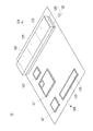
図1〜図3および図5に示すように、実施形態に係るトイレユニット10は、地下に埋設された収容空間55、65を備える地下貯蔵槽40と、予め組み立てられた状態で地下貯蔵槽40に収容されており、使用に際し地下貯蔵槽40から地面に取り出されて大便用仮設トイレ20および小便用仮設トイレ30を使用可能な状態にするトイレ組立品70とを有している。   As shown in FIGS. 1 to 3 and 5, the toilet unit 10 according to the embodiment includes an underground storage tank 40 including accommodation spaces 55 and 65 embedded underground, and an underground storage tank 40 in a preassembled state. And a toilet assembly 70 that is taken out of the underground storage tank 40 to the ground when in use and makes the temporary toilet 20 for stool and the temporary toilet 30 for urine usable.

トイレユニット10は、震災時等の非常時に備えて、区画された所定の土地に予め設置されている。図示例では、幅(W)3000mm(図1中の矢印a方向)、奥行き(D)4000mm(図1中の矢印b方向)に区画された12m程度の面積の土地にトイレユニット10一式を設置させている。トイレユニット10を設置させる土地としては、例えば、災害時の指定非難場所や、公園、空き地などが挙げられる。 The toilet unit 10 is installed in advance on a predetermined predetermined area in preparation for an emergency such as an earthquake disaster. In the illustrated example, the toilet unit 10 set is set on a land of about 12 m 2 divided into a width (W) of 3000 mm (in the direction of arrow a in FIG. 1) and a depth (D) of 4000 mm (in the direction of arrow b in FIG. 1). It is installed. Examples of the land on which the toilet unit 10 is installed include a designated condemned place at the time of a disaster, a park, and a vacant land.

図4に示すように、大便用仮設トイレ20および小便用仮設トイレ30は不使用時には、地下貯蔵槽40の開口部を覆うハッチ57、67や、トイレ用備品などを収容させる隠蔽部材120を地上に露出させた状態で配置される。   As shown in FIG. 4, when the stool temporary toilet 20 and the urine temporary toilet 30 are not in use, the hatches 57 and 67 covering the opening of the underground storage tank 40 and the concealing member 120 for accommodating toilet fixtures are provided on the ground. It is arranged in an exposed state.

トイレユニット10は、地下に埋設された大便用便槽100と、大便用便槽100に連通させて地上に設置された大便用便器110とを有している(図7をも参照)。大便用便器110は、3つを1セットとして並設される。大便用仮設トイレ20の不使用時は、それぞれの大便用便器111、112、113を隠蔽部材120によって覆わせる。これにより、大便用便器111、112、113を外部から隠蔽させた状態で保持できる。   The toilet unit 10 includes a stool toilet 100 embedded in the basement and a stool toilet 110 installed on the ground in communication with the stool toilet 100 (see also FIG. 7). The toilet bowls 110 for stool are arranged side by side as one set. When the stool temporary toilet 20 is not used, the stool toilets 111, 112, 113 are covered with the concealment member 120. Thereby, toilet bowl 111, 112, 113 for stool can be hold | maintained in the state concealed from the outside.

図5に示すように、大便用便槽100は、コンクリート製の内壁によって区画された収容空間105を備える。大便用便槽100の大きさは、例えば、幅(W)3000mm、奥行き(D)1400mm、深さ(H)1800mm程度に形成される。大便用便槽100の大きさは、要求される排泄物の収容能力に応じて適宜変更することが可能なものであり、上記の寸法例に限定されるものではない。   As shown in FIG. 5, the stool stool 100 includes an accommodation space 105 partitioned by a concrete inner wall. The size of the toilet stool 100 is, for example, formed to have a width (W) of 3000 mm, a depth (D) of 1400 mm, and a depth (H) of about 1800 mm. The size of the toilet stool 100 can be appropriately changed according to the required capacity for excreta, and is not limited to the above-described dimension example.

大便用便槽100は、開口部106と、開口部106を覆うように取り付けられるハッチ107とを有している。大便用便槽100内に収容した排泄物は、開口部106を介して地上に汲み上げることが可能になっている。   The stool stool 100 includes an opening 106 and a hatch 107 attached to cover the opening 106. The excrement stored in the toilet stool 100 can be pumped up to the ground through the opening 106.

開口部106の周囲には、開口部106とハッチ107との間から大便用便槽100内へ雨水が流入することを防止するための雨水止め金具109を設けている。雨水止め金具109は、開口部106の周囲を囲ませるように配置される。ハッチ107は、雨水止め金具109に引っ掛け自在なL字金具108を有している。ハッチ107には、トイレボックス収容槽50の内部を覗き見ることを可能にするための覗き窓などを適宜設けることが可能である。   Around the opening 106, there is provided a rainwater stopper 109 for preventing rainwater from flowing into the toilet stool 100 from between the opening 106 and the hatch 107. The rainwater stopper 109 is arranged so as to surround the periphery of the opening 106. The hatch 107 has an L-shaped metal fitting 108 that can be hooked on the rainwater stopping metal fitting 109. The hatch 107 can be appropriately provided with a viewing window or the like for allowing the inside of the toilet box storage tank 50 to be peeked.

図4、図8(A)に示すように、隠蔽部材120は、大便用便器111、112、113の周囲を囲む側壁部材121と、側壁部材121に着脱自在に取り付けられる屋根部材126とを有している。   As shown in FIGS. 4 and 8A, the concealment member 120 has a side wall member 121 surrounding the toilet bowl 111, 112, 113 and a roof member 126 that is detachably attached to the side wall member 121. is doing.

側壁部材121は、プレキャストコンクリート(PCコンクリート)によって製作している。側壁部材121は、高さ450mm程度に形成している。   The side wall member 121 is made of precast concrete (PC concrete). The side wall member 121 is formed with a height of about 450 mm.

屋根部材126は、鉄板によって製作している。側壁部材121と屋根部材126とによって区画された内部空間125内には、大便用便槽100以外にもトイレ用備品等を収納させておくことが可能である。この内部空間125は、大便用仮設トイレ20の使用時にはトイレ空間75の一部を構成する(図8(A)をも参照)。   The roof member 126 is made of an iron plate. In the internal space 125 defined by the side wall member 121 and the roof member 126, toilet fixtures and the like can be stored in addition to the toilet stool 100. The internal space 125 constitutes a part of the toilet space 75 when the stool temporary toilet 20 is used (see also FIG. 8A).

大便用仮設トイレ20の不使用時は、屋根部材126をベンチなどして利用することが可能である。また、通行人等が誤ってつまずくようなことがないように、屋根部材126とともに側壁部材121を所定の高さだけ地上に露出させて配置している。   When the stool temporary toilet 20 is not used, the roof member 126 can be used as a bench or the like. Further, the side wall member 121 is arranged with a predetermined height exposed on the ground together with the roof member 126 so that a passerby or the like does not trip accidentally.

隠蔽部材120の内部空間125は、側壁部材121によって大便用便器111、112、113ごとに区画されている。1つの大便用便器の周囲には、例えば、幅900mm、奥行き800mm程度の空間が形成される。大便用便器111、112、113は、例えば、内部空間125内においてボルト締めによって固定して設置される。   The internal space 125 of the concealing member 120 is partitioned by the side wall member 121 for each toilet bowl 111, 112, 113. For example, a space having a width of about 900 mm and a depth of about 800 mm is formed around one toilet bowl. The toilet bowls 111, 112, and 113 for stool are fixedly installed in the internal space 125 by bolting, for example.

隠蔽部材120の内部空間125内には、各大便用便器111、112、113をそれぞれ識別させるための識別プレート129を取り付けている。識別プレート129には、アルファベットや数字などが表示されており、使用者がどの大便用便器111、112、113を使用しているのかということなどを外部から確認することが可能になっている(図1を参照)。   In the internal space 125 of the concealing member 120, an identification plate 129 for identifying each toilet bowl 111, 112, 113 is attached. Alphabets and numbers are displayed on the identification plate 129, and it is possible to confirm from the outside which urinal 111, 112, 113 the user is using, etc. ( (See FIG. 1).

屋根部材126には、簡易式の鍵(図中省略)を備え付けさせることができる。大便用仮設トイレ20の不使用時に屋根部材126が取り外されることを防止するためである。これにより、内部空間125内に収納させたトイレ用備品の盗難などを防止することが可能になる。   The roof member 126 can be provided with a simple key (not shown). This is to prevent the roof member 126 from being removed when the stool temporary toilet 20 is not used. As a result, theft of toilet equipment stored in the internal space 125 can be prevented.

図6、図10(B)に示すように、トイレ組立品70は、外壁部材73および外壁部材73に開閉自在に取り付けられたドア部材80を備えたトイレボックス71と、地上に設置された2つのトイレボックス71間にトイレ空間75を区画するために用いられる補助正面パネル部材91および補助背面パネル部材93と、小便用仮設トイレ30に用いられる小便用便器をなす尿壁板130とを備える。   As shown in FIGS. 6 and 10B, a toilet assembly 70 includes an outer wall member 73 and a toilet box 71 having a door member 80 attached to the outer wall member 73 so as to be openable and closable, and 2 installed on the ground. The auxiliary front panel member 91 and the auxiliary back panel member 93 used for partitioning the toilet space 75 between the two toilet boxes 71, and the urine wall plate 130 forming the toilet for urine used for the temporary toilet 30 for urine are provided.

外壁部材73は、平板状のパネル部材によって構成される。1つのトイレボックスにつき、両側面用、および背面用の3枚のパネル部材が用いられる。   The outer wall member 73 is configured by a flat panel member. Three panel members for both sides and for the back are used for one toilet box.

トイレボックス71のドア部材80は、トイレボックス71の正面側に配置される(図6を参照)。トイレボックス71の背面側に位置する背面パネル部材74がドア部材80に向かい合わせるように配置される。また、トイレボックス71の両側面に位置する側面パネル部材73は互いに向かい合わせて配置される。   The door member 80 of the toilet box 71 is disposed on the front side of the toilet box 71 (see FIG. 6). The back panel member 74 located on the back side of the toilet box 71 is disposed so as to face the door member 80. Further, the side panel members 73 located on both side surfaces of the toilet box 71 are arranged facing each other.

ドア部材80は、ヒンジ81を介してパネル部材73に開閉自在に取り付けられる。図6(A)中の左側に示すトイレボックス71は、図7中の左側に配置された他の大便用便器112の周囲を覆うように配置される。このトイレボックス71には、補助正面パネル部材91の軸部材92を連結させるための連結ヒンジ82を設けている。一方、図6(A)中の右側に示すトイレボックス71は、図7中の右側に配置された他の大便用便器113の周囲を覆うように配置される。   The door member 80 is attached to the panel member 73 through a hinge 81 so as to be freely opened and closed. The toilet box 71 shown on the left side in FIG. 6A is arranged so as to cover the periphery of another toilet bowl 112 arranged on the left side in FIG. The toilet box 71 is provided with a connecting hinge 82 for connecting the shaft member 92 of the auxiliary front panel member 91. On the other hand, the toilet box 71 shown on the right side in FIG. 6A is arranged so as to cover the periphery of another toilet bowl 113 arranged on the right side in FIG.

パネル部材73を構成する材料にはポリエチレンを利用している。ドア部材80を構成する材料にもポリエチレンを利用している。トイレボックス71は、高さ1600mm程度に形成している。   Polyethylene is used as the material constituting the panel member 73. Polyethylene is also used as a material constituting the door member 80. The toilet box 71 has a height of about 1600 mm.

トイレボックス71のドア部材80の上端側およびトイレボックス71の背面パネル部材74にはトイレボックス71内の空気を換気させるための換気口83を設けている。換気口83は、例えば、高さ50mm、幅600mm程度に形成することが可能である。換気口83は、トイレボックス71を使用する際に、トイレボックス71の内部とトイレボックス71の外部とにおいて空気を循環させるために用いられる。   The upper end side of the door member 80 of the toilet box 71 and the back panel member 74 of the toilet box 71 are provided with a vent 83 for ventilating the air in the toilet box 71. The ventilation port 83 can be formed to have a height of about 50 mm and a width of about 600 mm, for example. The vent 83 is used to circulate air inside the toilet box 71 and outside the toilet box 71 when the toilet box 71 is used.

トイレボックス71は、隠蔽部材120の側壁部材121に連結可能に設けられる。図8(A)、図8(C)に示すように、トイレボックス71の側壁に設置した固定プレート86によって隠蔽部材120の側壁部材121に対してトイレボックス71を固定させることが可能である。   The toilet box 71 is provided so as to be connectable to the side wall member 121 of the concealing member 120. As shown in FIGS. 8A and 8C, the toilet box 71 can be fixed to the side wall member 121 of the concealing member 120 by a fixing plate 86 installed on the side wall of the toilet box 71.

側壁部材121から取り外した屋根部材126は、トイレボックス71の天井部分74に連結される。屋根部材126の裏面に設けられた枠材127に、トイレボックス71の上端部をはめ込むことによって、トイレボックス71と屋根部材126とを連結させることができる(図8(B)を参照)。図7に示すように、トイレボックス71の天井部分74に屋根部材126を取り付けることによって、大便用便器111、112、113が外部から隠蔽される。   The roof member 126 removed from the side wall member 121 is connected to the ceiling portion 74 of the toilet box 71. The toilet box 71 and the roof member 126 can be coupled by fitting the upper end of the toilet box 71 into the frame member 127 provided on the back surface of the roof member 126 (see FIG. 8B). As shown in FIG. 7, the toilet member 111, 112, 113 is concealed from the outside by attaching the roof member 126 to the ceiling portion 74 of the toilet box 71.

大便用仮設トイレ20の使用時、使用者を外部から隠蔽させために、例えば、地上からトイレボックス71の天井部分74までの高さを2000mm程度に設定することが望ましい。ただし、トイレボックス71自体の高さを2000mmとすると、地下貯蔵槽40からのトイレボックス71の取り出し作業や、地上におけるトイレボックス71の組み付け作業が煩雑なものとなる虞がある。そこで、側壁部材121の高さを450mm程度とし、側壁部材121に連結されるトイレボックス71の高さを1600mm程度とし、側壁部材121とトイレボックス71とを連結させることによって、約2000mm程度の高さのトイレ空間75を区画させている。トイレボックス71の大型化を抑制することによって、トイレボックス71の取り扱いが煩雑になることが防止される。   In order to conceal the user from outside when using the temporary toilet 20 for stool, for example, the height from the ground to the ceiling portion 74 of the toilet box 71 is preferably set to about 2000 mm. However, if the height of the toilet box 71 itself is 2000 mm, the work of taking out the toilet box 71 from the underground storage tank 40 and the work of assembling the toilet box 71 on the ground may be complicated. Therefore, the height of the side wall member 121 is set to about 450 mm, the height of the toilet box 71 connected to the side wall member 121 is set to about 1600 mm, and the side wall member 121 and the toilet box 71 are connected to each other, thereby increasing the height of about 2000 mm. The toilet space 75 is partitioned. By suppressing the enlargement of the toilet box 71, the handling of the toilet box 71 is prevented from becoming complicated.

トイレボックス71は、側壁部材121に連結させた状態で側壁部材121に対して固定させられる。固定は、トイレボックス71の側面に位置するパネル部材73に溶接された固定プレート86を側壁部材121に対してネジ止めして行っている(図8(C)を参照)。側壁部材121には、固定プレート86を固定させるためのネジ穴が予め設けられる。   The toilet box 71 is fixed to the side wall member 121 while being connected to the side wall member 121. The fixing is performed by screwing a fixing plate 86 welded to the panel member 73 located on the side surface of the toilet box 71 to the side wall member 121 (see FIG. 8C). The side wall member 121 is provided with a screw hole for fixing the fixing plate 86 in advance.

補助正面パネル部材91および補助背面パネル部材93は、3つの大便用便器を1セットにして並設させて使用する際に、使用するトイレボックス71の個数を減らすために用いられるものである。図8(A)に示すように、トイレユニット10にあっては、一の大便用便器111を設置し、一の大便用便器111の両隣に他の大便用便器112、113を並設させている。トイレボックス71を他の大便用便器112、113のそれぞれに配置することによって、他の大便用便器112、113の周囲にトイレ空間75が区画される。また、一の大便用便器111の側方において、トイレボックス71の側壁が向かい合わせて配置される。したがって、一の大便用便器111の正面側に補助正面パネル部材91を配置し、一の大便用便器111の背面側に補助背面パネル部材93を配置することによって、一の大便用便器111の周囲を覆うトイレ空間75を区画することができる。   The auxiliary front panel member 91 and the auxiliary back panel member 93 are used to reduce the number of toilet boxes 71 to be used when three toilet bowls are used in parallel. As shown in FIG. 8A, in the toilet unit 10, one toilet bowl 111 is installed, and the other toilet bowls 112 and 113 are arranged in parallel on both sides of the one toilet bowl 111. Yes. By disposing the toilet box 71 in each of the other toilet bowls 112 and 113, a toilet space 75 is partitioned around the other toilet bowls 112 and 113. In addition, on the side of one toilet bowl 111, the side wall of the toilet box 71 is disposed facing each other. Therefore, by arranging the auxiliary front panel member 91 on the front side of the one toilet bowl 111 and arranging the auxiliary rear panel member 93 on the back side of the one toilet bowl 111, Can be partitioned.

補助正面パネル部材91を構成する材料にはポリエチレンを利用している。補助正面パネル部材91は、トイレボックス71に組み付けられるドアとして構成されている。補助正面パネル部材91の軸部材92をトイレボックス71の連結ヒンジ82にはめ込むことによって、トイレボックス71に連結させられる(図6を参照)。   Polyethylene is used as the material constituting the auxiliary front panel member 91. The auxiliary front panel member 91 is configured as a door that is assembled to the toilet box 71. By inserting the shaft member 92 of the auxiliary front panel member 91 into the connecting hinge 82 of the toilet box 71, the auxiliary front panel member 91 is connected to the toilet box 71 (see FIG. 6).

補助背面パネル部材93を構成する材料にはポリエチレンを利用している。補助背面パネル部材93は、トイレボックス71の背面側に予め取り付けられた連結部材72に連結可能に構成されている。また、補助背面パネル部材93は、屋根部材126の裏面に設けられた枠部材127を介して屋根部材126に連結させることが可能になっている。   Polyethylene is used as the material constituting the auxiliary back panel member 93. The auxiliary back panel member 93 is configured to be connectable to a connecting member 72 attached in advance to the back side of the toilet box 71. The auxiliary back panel member 93 can be connected to the roof member 126 via a frame member 127 provided on the back surface of the roof member 126.

図10(B)に示すように、尿壁板130は、排泄された尿を受ける斜壁部131と、鉛直方向に伸びる背面部133と、上端側に配置された平板部135とを有している。尿壁板130は、内部に空洞部分が形成されるように鉄骨を組み付けて構成している。このように構成することによって、尿壁板130の軽量化を図っている。   As shown in FIG. 10 (B), the urine wall plate 130 includes a slanted wall portion 131 that receives excreted urine, a back surface portion 133 that extends in the vertical direction, and a flat plate portion 135 that is disposed on the upper end side. ing. The urine wall plate 130 is constructed by assembling a steel frame so that a hollow portion is formed inside. By configuring in this way, the weight of the urine wall board 130 is reduced.

尿壁板130の平板部135は、尿壁板130を収容する小便トイレ用収容槽60の排尿口61の周囲に設けた枠材64に引っ掛け自在な引っ掛け部138を有している(図5を参照)。尿壁板130の背面部133には、排尿口61の近傍に設けられた棒形状の支持部材63を挿通させるための筒部材139を取り付けている(図10(A)を参照)。   The flat plate portion 135 of the urine wall plate 130 has a hook portion 138 that can be hooked on a frame member 64 provided around the urine outlet 61 of the urinal toilet storage tank 60 that stores the urine wall plate 130 (FIG. 5). See). A cylindrical member 139 for inserting a rod-shaped support member 63 provided in the vicinity of the urination port 61 is attached to the back surface portion 133 of the urine wall plate 130 (see FIG. 10A).

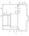
図5に示すように、地下貯蔵槽40は、トイレボックス71を収容するトイレボックス収容槽50と、尿壁板130を収容する小便トイレ用収容槽60とを有している。トイレボックス収容槽50内には、トイレボックス71以外にも、トイレユニット10に用いられるトイレ用備品を収容させている。   As shown in FIG. 5, the underground storage tank 40 includes a toilet box storage tank 50 for storing the toilet box 71 and a urinal toilet storage tank 60 for storing the urine wall plate 130. In addition to the toilet box 71, toilet equipment used for the toilet unit 10 is accommodated in the toilet box accommodation tank 50.

トイレボックス収容槽50は、コンクリート製の内壁によって区画された収容空間55を備えている。トイレボックス収容槽50は、例えば、幅(W)3000mm、奥行き(D)1200mm、深さ(H)1600mm程度に形成される。トイレボックス収容槽50の大きさは、収容させるトイレ組立品70やトイレ用備品の大きさ、外形形状などに応じて適宜変更することが可能なものであり、上記の寸法例に特に限定されるものではない。   The toilet box storage tank 50 includes a storage space 55 defined by a concrete inner wall. The toilet box storage tank 50 is formed to have a width (W) of 3000 mm, a depth (D) of 1200 mm, and a depth (H) of about 1600 mm, for example. The size of the toilet box storage tank 50 can be appropriately changed according to the size of the toilet assembly 70 and toilet equipment to be accommodated, the outer shape, and the like, and is particularly limited to the above dimension example. It is not a thing.

トイレボックス収容槽50は、開口部56と、開口部56を覆うように取り付けられるハッチ57とを有している。トイレボックス収容槽50内からトイレボックス71を取り出す際に、ハッチ57が取り外される。平常時は、開口部56を覆わせた状態でハッチ57を地上に配置させている(図4を参照)。   The toilet box storage tank 50 includes an opening 56 and a hatch 57 attached so as to cover the opening 56. When the toilet box 71 is taken out from the toilet box storage tank 50, the hatch 57 is removed. In normal times, the hatch 57 is arranged on the ground with the opening 56 covered (see FIG. 4).

開口部56の周囲には、開口部56とハッチ57との間からトイレボックス収容槽50内へ雨水が流入することを防止するための雨水止め金具59を設けている。雨水止め金具59は、開口部56の周囲を囲むように配置している。ハッチ57は、雨水止め金具59に引っ掛け自在なL字金具58を有している。   Around the opening 56, a rainwater stopper 59 is provided to prevent rainwater from flowing into the toilet box storage tank 50 from between the opening 56 and the hatch 57. The rainwater stop fitting 59 is arranged so as to surround the periphery of the opening 56. The hatch 57 has an L-shaped metal fitting 58 that can be hooked on the rainwater stopping metal fitting 59.

ハッチ57には、簡易に開け閉めを行うことが可能な小型の小蓋部53を設置している。小蓋部53は、例えば、作業者が開け閉めを容易に行うことが可能となるように、20cm×30cm程度の大きさのものを準備することが好ましい。また、ハッチ57には、トイレボックス収容槽50の内部を覗き見ることを可能にするための覗き窓などを適宜設けることが可能である。   The hatch 57 is provided with a small small lid portion 53 that can be easily opened and closed. For example, it is preferable to prepare a small lid portion 53 having a size of about 20 cm × 30 cm so that an operator can easily open and close the small lid portion 53. The hatch 57 can be appropriately provided with a viewing window or the like for allowing the inside of the toilet box storage tank 50 to be peeked.

トイレボックス71を使用する際、すなわち、大便用仮設トイレ20の使用時は、トイレボックス収容槽50の内部が空の状態となるため、トイレボックス収容槽50を廃棄物を収容させるためのゴミ箱として利用することが可能である。震災時などの非常時においては、高齢者や身体障害者などが排出する廃棄物が多量に排出されることが予測される。例えば、このような廃棄物を収容するためのごみ箱としてトイレボックス収容槽50を活用することができる。トイレボックス収容槽50をゴミ箱として利用する際、比較的小型の小蓋部53を開け閉めすることにより、開口部56を介したゴミの投下を安全かつ円滑に行うことが可能になる。   When the toilet box 71 is used, that is, when the stool temporary toilet 20 is used, the inside of the toilet box storage tank 50 is empty, so that the toilet box storage tank 50 is used as a trash can for storing waste. It is possible to use. In the event of an emergency such as an earthquake disaster, it is predicted that a large amount of waste will be discharged by elderly people and persons with disabilities. For example, the toilet box storage tank 50 can be utilized as a trash box for storing such waste. When the toilet box storage tank 50 is used as a trash box, by opening and closing the relatively small small lid portion 53, it becomes possible to drop the trash through the opening 56 safely and smoothly.

トイレボックス収容槽50には、ゴミ捕集用のネット182を装着させるためのガイドレール181を取り付けている。トイレボックス収容槽50をゴミ箱として使用する際、ゴミ捕集用のネット182をトイレボックス収容槽50の収容空間55内に設置し、開口部56から投げ込まれるゴミを捕集させることを可能にしている。ゴミ捕集用のネット182は、ナイロン材質の紐を網目状に結んで構成された公知のものである。ゴミ捕集用のネット182の両端には、ガイドレール181に対してゴミ捕集用のネット182を移動可能に取り付けるためのローラー183を設置している。ゴミ捕集用のネット182は、未使用時は、折り畳んだ状態でトイレボックス収容槽50内に収容させておくことが可能である。   A guide rail 181 for attaching a net 182 for collecting garbage is attached to the toilet box storage tank 50. When the toilet box storage tank 50 is used as a trash box, a net 182 for collecting garbage is installed in the storage space 55 of the toilet box storage tank 50 so that the trash thrown from the opening 56 can be collected. Yes. The net 182 for collecting garbage is a publicly known one configured by connecting nylon strings in a mesh shape. At both ends of the dust collection net 182, rollers 183 are installed for movably attaching the dust collection net 182 to the guide rail 181. The garbage collection net 182 can be stored in the toilet box storage tank 50 in a folded state when not in use.

ゴミ捕集用のネット182をトイレボックス収容槽50の長手方向に設置したガイドレール181に沿ってスライド移動可能に取り付けることによって、捕集させたゴミを開口部56の側に手繰り寄せることを可能にしている。これにより、開口部56からのゴミの取り出し作業の作業性の向上を図ることができる(図2を参照)。   By attaching the net 182 for collecting garbage so as to be slidable along the guide rail 181 installed in the longitudinal direction of the toilet box storage tank 50, it is possible to pull the collected garbage to the opening 56 side. I have to. As a result, it is possible to improve the workability of taking out dust from the opening 56 (see FIG. 2).

小便トイレ用収容槽60は、コンクリート製の内壁によって区画された収容空間65を備えている。小便トイレ用収容槽60は、例えば、幅(W)3000mm、奥行き(D)1000mm、深さ(H)1100mm程度に形成される。小便トイレ用収容槽60の大きさは、収容させるトイレ組立品70やトイレ用備品の大きさ、外形形状などに応じて適宜変更することが可能なものであり、上記の寸法例に特に限定されるものではない。   The urinal toilet storage tank 60 includes a storage space 65 defined by a concrete inner wall. The urinal toilet storage tank 60 is formed with, for example, a width (W) of 3000 mm, a depth (D) of 1000 mm, and a depth (H) of about 1100 mm. The size of the urinal toilet storage tank 60 can be appropriately changed according to the size of the toilet assembly 70 and toilet equipment to be accommodated, the outer shape, and the like, and is particularly limited to the above dimension example. It is not something.

図5、図9に示すように、小便トイレ用収容槽60は、尿壁板130を収容および取り出し可能に設けられた排尿口61と、地上に連通する開口部66と、開口部66を覆うように取り付けられるハッチ67とを有している。ハッチ67には、雨水を貯水させるための貯水タンク150を配置させる台座151を取り付けている。   As shown in FIGS. 5 and 9, the urinal toilet storage tank 60 covers the urination port 61 provided so as to accommodate and take out the urine wall plate 130, the opening 66 communicating with the ground, and the opening 66. And a hatch 67 attached in this manner. A pedestal 151 on which a water storage tank 150 for storing rainwater is disposed is attached to the hatch 67.

小便トイレ用収容槽60の排尿口61の周囲には、排尿口61から小便トイレ用収容槽60内へ雨水が流入することを防止するための枠材64を設けている(図10(B)を参照)。   A frame member 64 for preventing rainwater from flowing into the urinal toilet storage tank 60 from the urine outlet 61 is provided around the urination opening 61 of the urinal toilet storage tank 60 (FIG. 10B). See).

小便トイレ用収容槽60の開口部66の周囲には、開口部66から小便トイレ用収容槽60内へ雨水が流入することを防止するための雨水止め金具69を設けている。ハッチ67は、雨水止め金具69に引っ掛け自在なL字金具68を有している。ハッチ67には、小便トイレ用収容槽60の内部を覗き見ることを可能にするための覗き窓などを適宜設けることが可能である。   A rainwater stop fitting 69 is provided around the opening 66 of the urinal toilet storage tank 60 to prevent rainwater from flowing into the urinal toilet storage tank 60 from the opening 66. The hatch 67 has an L-shaped metal fitting 68 that can be hooked on the rainwater stopping metal fitting 69. The hatch 67 can be appropriately provided with a viewing window or the like for allowing the inside of the urinal toilet storage tank 60 to be peeked.

尿壁板130の不使用時には、尿壁板130の平板部135が、排尿口61を覆う覆い蓋として機能する(図4を参照)。尿壁板130の平板部135に設けた引っ掛け部138を排尿口61の周囲に設けられた枠材64に引っ掛けさせることにより、尿壁板130に位置ずれが生じることを防止することが可能になっている。   When the urine wall plate 130 is not used, the flat plate portion 135 of the urine wall plate 130 functions as a cover lid that covers the urination port 61 (see FIG. 4). By hooking the hook portion 138 provided on the flat plate portion 135 of the urine wall plate 130 to the frame member 64 provided around the urination port 61, it is possible to prevent the urine wall plate 130 from being displaced. It has become.

図10(A)に示すように、排尿口61の近傍には、回転可能に設けられた受け板62と、棒形状の支持部材63とを設置している。尿壁板130を使用する際は、小便トイレ用収容槽60の排尿口61に向けて直上に尿壁板130を持ち上げて地上に取り出す。取り出した尿壁板130は、受け板62の上に配置させる。また、尿壁板130の背面部133に設けた筒部材139内に支持部材63を挿入させることにより、尿壁板130を固定させることが可能になっている(図10(B)を参照)。尿壁板130を使用する際、すなわち、小便用仮設トイレ30の使用時は、小便トイレ用収容槽60の内部が空の状態となる。このため、小便トイレ用収容槽60を尿壁板130に対して排泄された排泄物を収容するための小便用便槽として利用することができる。   As shown in FIG. 10A, in the vicinity of the urination port 61, a receiving plate 62 provided rotatably and a bar-shaped support member 63 are installed. When the urine wall board 130 is used, the urine wall board 130 is lifted right above the urine outlet 61 of the urinal toilet storage tank 60 and taken out to the ground. The removed urine wall plate 130 is placed on the receiving plate 62. In addition, the urine wall plate 130 can be fixed by inserting the support member 63 into the cylindrical member 139 provided on the back surface portion 133 of the urine wall plate 130 (see FIG. 10B). . When the urine wall board 130 is used, that is, when the urinal temporary toilet 30 is used, the interior of the urinal toilet storage tank 60 is empty. For this reason, the urinal toilet storage tank 60 can be used as a urinal toilet tank for storing excreta excreted with respect to the urine wall board 130.

図10(B)に示すように、トイレユニット10は、小便用仮設トイレ30に組み付けて用いられるガイド板140を有している。ガイド板140には、傾斜面141が設けられており、使用者が排泄した排泄物を排尿口61へ導くことができる。   As shown in FIG. 10B, the toilet unit 10 includes a guide plate 140 that is used by being assembled in the temporary toilet 30 for urine. The guide plate 140 is provided with an inclined surface 141, and excrement excreted by the user can be guided to the urination port 61.

ガイド板140の下端部は、排尿口61の周囲に設置させた枠材64にはめ込んで連結させることが可能になっている(図10(A)を参照)。ガイド板140の背面部には、棒形状の支持部材143を取り付けている。トイレユニット10が設置された地上部分には、支持部材143が挿入可能な筒部材144を予め設置している。ガイド板140の使用時は、ガイド板140の下端部を枠材64にはめ込んで連結させるとともに、支持部材143を筒部材144内に挿入して固定させている。固定させる際、ガイド板140の下端部と排尿口61との間に所定の間隔を設けることによって、ガイド板140に排泄された排泄物をガイド板140の傾斜面141を伝わらせて小便トイレ用収容槽60内に流れ込ませることを可能にしている。   The lower end portion of the guide plate 140 can be fitted and connected to the frame member 64 installed around the urination port 61 (see FIG. 10A). A bar-shaped support member 143 is attached to the back surface of the guide plate 140. A cylindrical member 144 into which the support member 143 can be inserted is installed in advance on the ground portion where the toilet unit 10 is installed. When the guide plate 140 is used, the lower end portion of the guide plate 140 is fitted and connected to the frame member 64, and the support member 143 is inserted into the cylindrical member 144 and fixed. When fixing, a predetermined interval is provided between the lower end portion of the guide plate 140 and the urination port 61, so that excrement excreted by the guide plate 140 is transmitted along the inclined surface 141 of the guide plate 140 for the urinal toilet It is possible to flow into the storage tank 60.

図5に示すように、小便用仮設トイレ30の不使用時には、ガイド板140をトイレボックス収容槽50に収容させることができる。   As shown in FIG. 5, the guide plate 140 can be stored in the toilet box storage tank 50 when the urinal temporary toilet 30 is not used.

図7、図11に示すように、トイレユニット10は、トイレボックス71のドア部材80に取り付けられるとともに大便用便槽100内に伸び、ドア部材80の開閉に伴い大便用便槽100内に収容された排泄物を拡散させてならす拡散器145を有している。   As shown in FIGS. 7 and 11, the toilet unit 10 is attached to the door member 80 of the toilet box 71 and extends into the stool tub 100, and is accommodated in the stool tub 100 as the door member 80 is opened and closed. A diffuser 145 for diffusing the excreted waste.

拡散器145は、トイレボックス71のドア部材80に取り付けられる棒状部147と、大便用便槽100内に配置される先端部149とを有している。先端部149は、波状に形成されており、ドア部材80の開閉に伴って排泄物を引っ掛けて拡散させる。拡散に伴い大便用便槽100内の排泄物の貯留高さが全体的に均一にならされる。   The diffuser 145 has a rod-shaped portion 147 attached to the door member 80 of the toilet box 71 and a tip portion 149 disposed in the toilet stool 100. The distal end portion 149 is formed in a wave shape, and catches and diffuses excrement as the door member 80 is opened and closed. Along with the diffusion, the stored height of the excrement in the stool tank 100 is made uniform as a whole.

大便用仮設トイレ20の不使用時は、隠蔽部材120の床に設けた穴部128に拡散器145の棒状部147を挿通させて配置し、拡散器145の先端部149を大便用便槽100内に収容させた状態で配置しておく(図8(A)を参照)。大便用仮設トイレ20の使用に際し、トイレボックス71を設置させた後、トイレボックス71のドア部材80の内側に拡散器145の棒状部147を固定させることによって、拡散器145を使用することが可能になる。固定方法は、ネジ止めなどを適宜採用することが可能である。   When the stool temporary toilet 20 is not used, the rod-shaped portion 147 of the diffuser 145 is inserted into the hole 128 provided in the floor of the concealing member 120, and the tip 149 of the diffuser 145 is placed in the toilet stool 100. It arrange | positions in the state accommodated in (refer FIG. 8 (A)). It is possible to use the diffuser 145 by fixing the rod-shaped portion 147 of the diffuser 145 inside the door member 80 of the toilet box 71 after installing the toilet box 71 when using the temporary toilet 20 for stool. become. As a fixing method, screwing or the like can be appropriately employed.

図1〜図3に示すように、トイレユニット10は、雨水を貯水させるための貯水タンク150と、仮設トイレの設置箇所周辺の地面を覆うように張設される防水シート160と、防水シート160を地面に対して支持するとともに防水シート160上に滞留させた雨水を貯水タンク150へ導流するパイプ材170とを有している。   As shown in FIGS. 1 to 3, the toilet unit 10 includes a water storage tank 150 for storing rainwater, a waterproof sheet 160 stretched so as to cover the ground around the installation location of the temporary toilet, and a waterproof sheet 160. And a pipe material 170 that guides rainwater retained on the waterproof sheet 160 to the water storage tank 150.

図5に示すように、貯水タンク150や防水シート160、パイプ材170は、不使用時には、トイレボックス収容槽50内に収容させている。   As shown in FIG. 5, the water storage tank 150, the waterproof sheet 160, and the pipe material 170 are accommodated in the toilet box accommodation tank 50 when not in use.

貯水タンク150は、ドラム缶に簡易式の蛇口を取り付けたものである。簡素な構成のものを用いることによって、トイレユニット10のコストの削減を図っている。   The water storage tank 150 is a drum can provided with a simple faucet. By using a simple configuration, the cost of the toilet unit 10 is reduced.

貯水タンク150を使用する際は、小便トイレ用収容槽60の開口部66を覆うハッチ67を裏返して配置し、ハッチ67に取り付けた台座151上に貯水タンク150を配置させている。貯水タンク150の底部が地面よりも高い位置にかさ上げされた状態で貯水タンク150に貯水させた雨水を使用することを可能にし、使用者の利便性を向上させている。   When the water storage tank 150 is used, the hatch 67 that covers the opening 66 of the urinal toilet storage tank 60 is turned upside down, and the water storage tank 150 is disposed on the base 151 attached to the hatch 67. It is possible to use rainwater stored in the water storage tank 150 in a state where the bottom of the water storage tank 150 is raised to a position higher than the ground, thereby improving user convenience.

防水シート160は、撥水加工が施された公知のビニールシートである。大便用仮設トイレ20の空きを待つ待機者や、小便用仮設トイレ30の使用者を雨水や日射から保護する機能を発揮する。   The waterproof sheet 160 is a known vinyl sheet that has been subjected to a water-repellent finish. The function of protecting the waiting person who waits for the vacant stool temporary toilet 20 and the user of the urinal temporary toilet 30 from rainwater and solar radiation is exhibited.

パイプ材170は、防水シート160の略中央位置に配置される主支柱パイプ181と、主支柱パイプ181に連結され防水シート160に滞留した雨水を貯水タンク150へ導流するための雨水パイプ191と、防水シート160を四隅において支持する補助支柱パイプ193と、補助支柱パイプ193同士を地面と略平行な方向において連結する補助連結パイプ195とを有している。各パイプは、鉄を材料とする公知のものである。   The pipe material 170 includes a main support pipe 181 disposed substantially at the center of the waterproof sheet 160, and a rainwater pipe 191 that is connected to the main support pipe 181 and guides rainwater staying in the waterproof sheet 160 to the water storage tank 150. The auxiliary support pipe 193 that supports the waterproof sheet 160 at the four corners, and the auxiliary connection pipe 195 that connects the auxiliary support pipes 193 in a direction substantially parallel to the ground. Each pipe is a known pipe made of iron.

主支柱パイプ181および補助支柱パイプ193は、地面に予め埋設させたパイプ材(図中省略)内に下端部を挿入させることによって建て付けられる。補助支柱パイプ193と補助連結パイプ195との連結は、はめ込み式の簡素な連結具196を利用して連結させられる。   The main support pipe 181 and the auxiliary support pipe 193 are built by inserting a lower end portion into a pipe material (not shown) embedded in the ground in advance. The auxiliary strut pipe 193 and the auxiliary connecting pipe 195 are connected using a simple fitting tool 196 of a fitting type.

主支柱パイプ181は、それぞれの補助支柱パイプ193に連結された梁部材198を備えている。梁部材198は、金属製のワイヤで構成されている。   The main column pipe 181 includes a beam member 198 connected to each auxiliary column pipe 193. The beam member 198 is made of a metal wire.

防水シート160は、梁部材198上に載置させることができる。防水シート160は、強風時などに備えて紐部材(図中省略)を利用して補助連結パイプ195に結び付けることができる。   The waterproof sheet 160 can be placed on the beam member 198. The waterproof sheet 160 can be tied to the auxiliary connecting pipe 195 using a string member (not shown) in preparation for a strong wind.

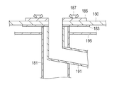
図12に示すように、雨水パイプ191は、主支柱パイプ181に一部を内挿させた状態で組み付けられる。雨水パイプ191は、貯水タンク160へ雨水を流すことが可能となるように、所定の角度の勾配を付けて設置される。防水シート160は、主支柱パイプ181に取り付けた受け皿183と押さえ蓋185との間に挟み込ませている。防水シート160は、取り付け用のボルト187によって主支柱パイプ181に固定される。   As shown in FIG. 12, the rainwater pipe 191 is assembled in a state where a part of the rainwater pipe 181 is inserted into the main support pipe 181. The rainwater pipe 191 is installed with a predetermined angle of gradient so that rainwater can flow into the water storage tank 160. The waterproof sheet 160 is sandwiched between a tray 183 attached to the main column pipe 181 and a presser lid 185. The waterproof sheet 160 is fixed to the main support pipe 181 with mounting bolts 187.

各パイプの内径寸法等は、特に限定されないが、防水シート160上に滞留させた雨水を貯水タンク150へ良好に導流させるためには、例えば、主支柱パイプ181の内径を60mm程度とし、雨水パイプ191の内径を50mm程度とすることが好ましい。   The inner diameter dimension of each pipe is not particularly limited, but in order to guide the rainwater retained on the waterproof sheet 160 to the water storage tank 150 satisfactorily, for example, the main strut pipe 181 has an inner diameter of about 60 mm and the rainwater The inner diameter of the pipe 191 is preferably about 50 mm.

図1、図8(A)に示すように、トイレユニット10は、大便用仮設トイレ20の使用時にトイレボックス71の背面側に設置される補強用パイプ材210を有している。補強用パイプ材210は、連結金具211を介してトイレボックス71の背面に連結される。補強用パイプ材210によってトイレボックス71の剛性が高められる。補強用パイプ材210は、鉄を材料とする公知のものである。   As shown in FIGS. 1 and 8A, the toilet unit 10 has a reinforcing pipe member 210 that is installed on the back side of the toilet box 71 when the stool temporary toilet 20 is used. The reinforcing pipe member 210 is connected to the back surface of the toilet box 71 via the connecting fitting 211. The rigidity of the toilet box 71 is increased by the reinforcing pipe member 210. The reinforcing pipe material 210 is a known material made of iron.

図1、図9に示すように、トイレユニット10は、小便用仮設トイレ30の使用時に小便用仮設トイレ30の背面側に設置される支持パイプ材220を有している。支持パイプ材220は、尿壁板130を支持し、尿壁板130が背面側へ倒れ込むことを防止する。支持パイプ材220は、鉄を材料とする公知のものである。   As shown in FIGS. 1 and 9, the toilet unit 10 includes a support pipe material 220 that is installed on the back side of the urinal temporary toilet 30 when the urinal temporary toilet 30 is used. The support pipe member 220 supports the urine wall plate 130 and prevents the urine wall plate 130 from falling to the back side. The support pipe material 220 is a known material made of iron.

支持パイプ材220には布材221を吊るしている。布材221は、小便用仮設トイレ30の背面側から小便用仮設トイレ30の使用者が視認されることを防止するための目隠しとして利用される。   A cloth material 221 is suspended from the support pipe material 220. The cloth material 221 is used as a blindfold for preventing the user of the temporary toilet 30 for urine from being visually recognized from the back side of the temporary toilet 30 for urine.

実施形態に係るトイレユニットの作用について説明する。   The operation of the toilet unit according to the embodiment will be described.

予め組み立てられた状態のトイレ組立品70を地下に埋設させた地下貯蔵槽40内に収容させておくことができる。使用時には、地下貯蔵槽40からトイレ組立品70を地上に取り出して組み付けるだけの簡易な作業によって、大便用仮設トイレ20および小便用仮設トイレ30を使用可能な状態にすることができる。地上においてトイレ組立品70の煩雑な組み立て作業を行う必要がないため、短時間で大便用仮設トイレ20および小便用仮設トイレ30を提供することができ、非常時における利便性の向上を図ることができる。   The toilet assembly 70 in a preassembled state can be accommodated in the underground storage tank 40 buried underground. At the time of use, the stool temporary toilet 20 and the urine temporary toilet 30 can be brought into a usable state by a simple operation of taking out the toilet assembly 70 from the underground storage tank 40 and assembling it. Since it is not necessary to perform complicated assembly work of the toilet assembly 70 on the ground, the stool temporary toilet 20 and the urine temporary toilet 30 can be provided in a short time, and the convenience in an emergency can be improved. it can.

震災時等に避難場所への搬送を行う手間が省かれるため、搬送に要する労力を軽減することができる。さらに、トイレユニット70の設置箇所を予め選定して設置箇所を周知させておくことにより、被災者への設置場所に関する情報伝達性を高めることができる。くわえて、便槽を地下に埋設する方式を採用しているため、便槽の容積を比較的大きく設計することができ、より多くの被災者に対応することができる。便槽の容積が大きくなるため、排泄物の汲み出し、および排泄物の搬送に費やす手間を軽減することができる。   Since the trouble of transporting to an evacuation site in the event of an earthquake or the like is saved, labor required for transport can be reduced. Furthermore, by selecting the installation location of the toilet unit 70 in advance and making the installation location known, it is possible to improve the information transmission regarding the installation location to the victim. In addition, since the toilet tank is embedded in the basement, the volume of the toilet tank can be designed to be relatively large, and more disaster victims can be accommodated. Since the volume of the toilet bowl is increased, it is possible to reduce the effort spent for pumping out excreta and transporting excreta.

大便用便器112の周囲にトイレ空間75を区画するためのトイレボックス71を、予め組み立てた状態でトイレボックス収容槽50内に収容させている。トイレボックス収容槽50から地上に取り出したトイレボックス71を大便用便器110の周囲に配置させる簡単な作業によって大便用仮設トイレ20を使用可能な状態にすることができる。さらに、トイレボックス71を取り出した後は、トイレボックス収容槽50を廃棄物を収容させるためのゴミ箱として利用することができるため、地下に埋設させた収容空間55を有効に活用することができる。   A toilet box 71 for partitioning the toilet space 75 around the toilet bowl 112 is housed in the toilet box housing tank 50 in a preassembled state. The stool temporary toilet 20 can be put into a usable state by a simple operation of placing the toilet box 71 taken out from the toilet box storage tank 50 around the stool toilet 110. Furthermore, after the toilet box 71 is taken out, the toilet box storage tank 50 can be used as a trash box for storing waste, so that the storage space 55 buried underground can be used effectively.

大便用仮設トイレ30の不使用時は、側壁部材121と屋根部材126とによって、大便用便器110を覆わせて外部から隠蔽させておくことができる。大便用便器110の破損などを防止することができ、長期間にわたって保管することが可能になる。大便用仮設トイレ30の使用時は、屋根部材126をトイレボックス71の天井部分74に取り付けることによって、トイレボックス71の屋根として転用することができる。トイレユニット10の部品点数を減らすことによって、コストの削減を図ることができる。   When the stool temporary toilet 30 is not used, the toilet member 110 can be covered and concealed from the outside by the side wall member 121 and the roof member 126. The toilet bowl 110 can be prevented from being damaged, and can be stored for a long time. When the stool temporary toilet 30 is used, the roof member 126 can be used as the roof of the toilet box 71 by attaching the roof member 126 to the ceiling portion 74 of the toilet box 71. The cost can be reduced by reducing the number of parts of the toilet unit 10.

一の大便用便器111を設置し、一の大便用便器111の両隣に他の大便用便器112、113を並設させることができる。トイレボックス71を他の大便用便器112、113にそれぞれ配置させ、それぞれのトイレボックス71の側壁によって一の大便用便器111の側方を囲ませている。このため、一の大便用便器111の正面側に補助正面パネル部材91を配置し、一の大便用便器111の背面側に補助背面パネル部材93を配置することによって、一の大便用便器111の周囲にトイレ空間75を区画することができる。トイレボックス71の側壁を一の大便用便器111と他の大便用便器112、113とにおいて共用化させているため、トイレボックス71の使用数を減らすことができ、コストの削減を図ることができる。さらに、大便用便器110を増設させているため、被災時などにはより多くの被災者に大便用仮設トイレ20を提供することができる。   One toilet bowl 111 can be installed, and other toilet bowls 112 and 113 can be juxtaposed on both sides of the one toilet bowl 111. The toilet box 71 is disposed in each of the other toilet bowls 112 and 113, and the side wall of the toilet bowl 111 is surrounded by the side wall of each toilet box 71. For this reason, the auxiliary front panel member 91 is arranged on the front side of the one toilet bowl 111, and the auxiliary rear panel member 93 is arranged on the back side of the one toilet bowl 111. A toilet space 75 can be defined around the periphery. Since the side wall of the toilet box 71 is shared by one toilet bowl 111 and the other toilet bowls 112 and 113, the number of toilet boxes 71 used can be reduced, and the cost can be reduced. . Furthermore, since the toilet toilet 110 is additionally provided, the stool temporary toilet 20 can be provided to more victims in the event of a disaster.

トイレボックス71のドア部材80に取り付けられた拡散器145が、ドア部材80を開閉させるたびに大便用便槽100内に収容させた排泄物を拡散させてならす。排泄物の貯留高さが全体的に均一になるため、より多くの排泄物を大便用便槽100内に収容させることができる。   The diffuser 145 attached to the door member 80 of the toilet box 71 diffuses excrement accommodated in the toilet bowl 100 each time the door member 80 is opened and closed. Since the stored height of the excrement becomes uniform as a whole, more excrement can be accommodated in the toilet stool 100.

尿壁板130を収容する小便トイレ用収容槽60を、尿壁板130に対して排泄された排泄物を収容するための小便用便槽として利用することができる。トイレユニット10に小便用仮設トイレ30を備えさせることができ、大便用仮設トイレ20および小便用仮設トイレ30を備える男性用のトイレ設備を提供することができる。   The urinal toilet storage tank 60 for storing the urine wall board 130 can be used as a urinal toilet tank for storing excretion excreted with respect to the urine wall board 130. The toilet unit 10 can be provided with a temporary toilet 30 for urine, and a male toilet facility including the temporary toilet 20 for stool and the temporary toilet 30 for urine can be provided.

防水シート160によって、大便用仮設トイレ20の空きを待つ待機者や小便用仮設トイレ30の使用者を雨水や日射から保護することができる。さらに、防水シート160に滞留させた雨水を貯水タンク150において貯水させることによって、雨水の再利用を行うことができる。震災時などのように水が不足する場合においても、トイレユニット10の清掃などに必要な水を確保することができる。   The waterproof sheet 160 can protect the waiting person waiting for the empty stool temporary toilet 20 and the user of the urine temporary toilet 30 from rainwater and solar radiation. Further, the rainwater retained in the waterproof sheet 160 can be stored in the water storage tank 150 so that the rainwater can be reused. Even when there is a shortage of water, such as during an earthquake, water necessary for cleaning the toilet unit 10 can be secured.

(他の改変例)
小便用仮設トイレ30に用いられる小便トイレ用収容槽60や尿壁板130が備えられていない形態のトイレユニット10を女性専用のトイレ設備として提供することが可能である。
(Other modifications)
It is possible to provide the toilet unit 10 in a form in which the urinal toilet storage tank 60 and the urine wall plate 130 used for the temporary toilet 30 for urine are not provided as a toilet facility dedicated to women.

女性専用のトイレ設備には、小便用仮設トイレ30に用いられる設備等が不要である。不要な設備を設けないことにより、トイレユニット10を女性専用のトイレ設備として提供することができる。   The toilet facilities for women only do not require the facilities used for the temporary toilet 30 for urine. By not providing unnecessary equipment, the toilet unit 10 can be provided as a female-only toilet equipment.

上述した実施形態は、適宜改変することが可能である。   The embodiment described above can be modified as appropriate.

隠蔽部材120の屋根部材126をトイレボックス71の屋根として転用させる実施形態を説明したが、例えば、トイレボックス71の天井部分74に通気性を有するすだれなどを配置し、これを屋根部材126の代わりに用いることも可能である。トイレ空間内に直接的に太陽光が照射されることを防止しつつ、トイレボックス内部の熱を効率的に逃がすことができ、使用者の快適性をより向上させることが可能になる。   Although the embodiment in which the roof member 126 of the concealing member 120 is diverted as the roof of the toilet box 71 has been described, for example, a blind that has air permeability is arranged on the ceiling portion 74 of the toilet box 71 and this is replaced with the roof member 126. It can also be used. While preventing sunlight from being directly irradiated into the toilet space, the heat inside the toilet box can be efficiently released, and the user's comfort can be further improved.

大便用便槽105内の臭気を低減させる対策として、例えば、大便用便槽100と地上とを連通する換気口などを適宜設置することが可能である。   As a measure for reducing the odor in the stool stool 105, for example, a ventilation port that communicates the stool stool 100 with the ground can be installed as appropriate.

大便用便器の設置数などは、使用予定者の人数に合わせて適宜変更することが可能である。例えば、3つの大便用便器を1セットとして増設することも可能であるし、大便用便器を1つずつ増設させることも可能である。   The number of toilet bowls installed can be appropriately changed according to the number of persons scheduled to use. For example, it is possible to add three toilet bowls as a set, or it is possible to add one toilet bowl one by one.

(大便用仮設トイレの変形例)
本変形例においては、大便用仮設トイレを使用可能な状態にするトイレボックスには、高さ方向に伸びる円筒形状の外形形状に形成された外壁部材を備えるトイレボックスが使用される。このような点において、平板状のパネル部材によって構成された外壁部材を備えるトイレボックスが使用される上述の実施形態と相違する。以下、図面を参照して本変形例について説明する。なお、同一の部材には同一の符号を付して、その説明を一部省略する。
(Modified example of temporary toilet for stool)
In the present modification, a toilet box including an outer wall member formed in a cylindrical outer shape extending in the height direction is used as a toilet box that makes a temporary toilet for stool usable. In such a point, it differs from the above-mentioned embodiment in which a toilet box provided with an outer wall member constituted by a flat panel member is used. Hereinafter, this modification will be described with reference to the drawings. In addition, the same code | symbol is attached | subjected to the same member and the description is partially abbreviate | omitted.

図13、図14を参照して、トイレボックス271が備える外壁部材273は、高さが約1600mm程度に形成された円筒形状に形成されている。隠蔽部材120の側壁部材121にトイレボックス271を取り付けた状態では、トイレボックス271の天井部分までの高さは、地面から約2000mm程度の高さとなる。大便用便器210の設置数は特に限定されないが、本変形例においては、大便用便器は1つのみ設置している。   Referring to FIGS. 13 and 14, the outer wall member 273 provided in the toilet box 271 is formed in a cylindrical shape having a height of about 1600 mm. In a state where the toilet box 271 is attached to the side wall member 121 of the concealing member 120, the height to the ceiling portion of the toilet box 271 is about 2000 mm from the ground. The number of installed toilet bowls 210 is not particularly limited, but in the present modification, only one toilet bowl is installed.

外壁部材273の内部には、トイレボックス271の高さ方向に伸びる所定の内部空間が形成されている。上述した実施形態に係るトイレボックス71と同様に、隠蔽部材120の側壁部材121に外壁部材273を組み付けることによって大便用便器210の周囲にトイレ空間275を区画させることができる。トイレ空間275を区画させることによって、大便用仮設トイレ220が使用可能な状態になる。使用時には、トイレ空間275の下側に位置するように換気口83が設けられる。   A predetermined internal space extending in the height direction of the toilet box 271 is formed inside the outer wall member 273. Similarly to the toilet box 71 according to the embodiment described above, the toilet space 275 can be partitioned around the toilet bowl 210 by assembling the outer wall member 273 to the side wall member 121 of the concealment member 120. By partitioning the toilet space 275, the stool temporary toilet 220 can be used. At the time of use, the ventilation opening 83 is provided so that it may be located under the toilet space 275.

トイレボックス271の外壁部材273には、断熱材292を取り付けることができる(図14(B)を参照)。断熱材には、例えば、家屋などに一般的に用いられるシート状の断熱材を使用できる。   A heat insulating material 292 can be attached to the outer wall member 273 of the toilet box 271 (see FIG. 14B). As the heat insulating material, for example, a sheet-shaped heat insulating material generally used in a house or the like can be used.

トイレボックス271の外壁部材273は、例えば、アルミ等の比較的軽量な部材によって構成することが好ましい。   The outer wall member 273 of the toilet box 271 is preferably constituted by a relatively lightweight member such as aluminum.

側壁部材121への外壁部材273の取り付けは、外壁部材273に設けられた支持部291を利用して行われる(図14(B)を参照)。図中省略するが、支持部291および側壁部材121には、ねじ穴が予め設けられており、支持部291を側壁部材121に載せた状態でねじを使用して固定を行うことが可能になっている。なお、側壁部材121への外壁部材273の取り付けは、このような形態に限定されず、両部材を強固に固定し得る限りにおいて適宜変更することが可能である。   Attachment of the outer wall member 273 to the side wall member 121 is performed using a support portion 291 provided on the outer wall member 273 (see FIG. 14B). Although not shown in the drawing, the support portion 291 and the side wall member 121 are provided with screw holes in advance, and can be fixed using screws with the support portion 291 placed on the side wall member 121. ing. The attachment of the outer wall member 273 to the side wall member 121 is not limited to such a form, and can be appropriately changed as long as both members can be firmly fixed.

トイレボックス271に取り付けられる屋根部材226は、トイレボックス271の天井側へトイレ空間275内の空気の流れが誘導されるように、半円形の内面形状を有している。後述する脱臭部材293による臭気の吸着を効率的に行うことを可能にするためである。なお、上述した実施形態と同様に、屋根部材226を、隠蔽部材120の屋根部材として共用する構成を採用することも可能である。このような構成における屋根部材の着脱、および外壁部材への屋根部材の取付け方法は、上述した実施形態において説明した方法と同様の方法を採用することができるため、説明は省略する。   The roof member 226 attached to the toilet box 271 has a semicircular inner surface shape so that the air flow in the toilet space 275 is guided to the ceiling side of the toilet box 271. This is because it is possible to efficiently perform odor adsorption by the deodorizing member 293 described later. In addition, it is also possible to employ | adopt the structure which shares the roof member 226 as a roof member of the concealment member 120 similarly to embodiment mentioned above. Since a method similar to the method demonstrated in embodiment mentioned above can be employ | adopted for the attachment or detachment method of the roof member in such a structure, and the attachment method of the roof member to an outer wall member, description is abbreviate | omitted.

屋根部材226の材質は、特に限定されないが、採光性を向上させるために、硬質の比較的薄肉な樹脂製パネル材などによって構成されることが好ましい。   The material of the roof member 226 is not particularly limited, but is preferably composed of a hard, relatively thin resin panel material or the like in order to improve daylighting.

トイレボックス271が備えるドア部材280には、外壁部材273の周方向に沿うスライド移動(図14(A)中の矢印で示す)によって開閉されるスライド開閉式のドア部材が用いられる。外壁部材273へのドア部材280の取り付けは、例えば、外壁部材273にスライド用のレールを設け、このレールに沿ってドアを移動させることを可能にする公知の取り付け方法を採用することができる。   As the door member 280 provided in the toilet box 271, a slide opening / closing type door member that is opened and closed by a sliding movement (indicated by an arrow in FIG. 14A) along the circumferential direction of the outer wall member 273 is used. For the attachment of the door member 280 to the outer wall member 273, for example, a known attachment method can be adopted in which a slide rail is provided on the outer wall member 273 and the door can be moved along the rail.

ドア部材280には、大便用便槽300へ伸びる拡散器140が取り付けられる。取り付け方法は、例えば、拡散器140の棒状部147をねじや接着材などによってドア部材280に固定させる方法が採用できる。なお、本変形例のように、ドア部材280にスライド開閉式のドア部材を利用する場合、押し引きして開閉が行われるドア部材を採用する場合と比較して、開閉時における大便用便槽300内の汚物の拡散を効率的に行うことができる。   A diffuser 140 that extends to the toilet stool 300 is attached to the door member 280. As an attachment method, for example, a method of fixing the rod-shaped portion 147 of the diffuser 140 to the door member 280 with a screw or an adhesive can be employed. In addition, when using a sliding opening / closing type door member for the door member 280 as in this modification, the toilet bowl for stool at the time of opening and closing is compared to the case of using a door member that is opened and closed by pushing and pulling. The filth in 300 can be diffused efficiently.

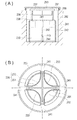
図15(A)、(B)を参照して、トイレボックス271は、トイレ空間275内の臭気を脱臭するための脱臭部材293を有している。脱臭部材293は、トイレ空間275の外部へ空気を流出し、空気を流出する際に臭気を脱臭することを可能にするものである。   Referring to FIGS. 15A and 15B, the toilet box 271 has a deodorizing member 293 for deodorizing the odor in the toilet space 275. The deodorizing member 293 allows air to flow out of the toilet space 275 and to deodorize the odor when the air flows out.

トイレボックス271にあっては、屋根部材226に脱臭部材293を取り付けている。これは、臭気の脱臭を効率的に行わせるためである。換気口63から取り入れられた空気aは、トイレボックス271内に滞留する空気a’とともにトイレボックス271の天井側へ上昇する。このため、トイレボックス271の天井側において効率的な脱臭を行うことが可能になる。   In the toilet box 271, a deodorizing member 293 is attached to the roof member 226. This is for efficiently deodorizing the odor. The air a taken in from the ventilation port 63 rises to the ceiling side of the toilet box 271 together with the air a ′ staying in the toilet box 271. For this reason, efficient deodorization can be performed on the ceiling side of the toilet box 271.

脱臭部材293は、網目を備える樹脂材質の筒部材によって構成されている。トイレ空間275内の空気が筒部材を通過する際、空気に含まれる臭気の要因となる微粒子が筒部材に吸着される。図示するように、脱臭部材293による吸着性を向上させるために、3つの筒部材を利用している。   The deodorizing member 293 is configured by a cylindrical member made of a resin material having a mesh. When the air in the toilet space 275 passes through the cylindrical member, fine particles that cause odor contained in the air are adsorbed by the cylindrical member. As shown in the drawing, in order to improve the adsorptivity by the deodorizing member 293, three cylindrical members are used.

外側に位置する筒部材の網目の間隔を、内側に位置する筒部材の網目の間隔よりも粗くすることにより、脱臭部材293全体における微粒子の吸着性を向上させている。脱臭部材293の上部には、着脱可能な蓋294を設置している。雨水がトイレ空間275内に流入することを防止するためである。   By making the intervals between the meshes of the cylindrical members located outside the meshes between the meshes of the cylindrical members located inside, the adsorptivity of the fine particles in the entire deodorizing member 293 is improved. A removable cover 294 is installed on the top of the deodorizing member 293. This is to prevent rainwater from flowing into the toilet space 275.

脱臭部材293として網目を備える筒部材を利用した形態を図示しているが、脱臭部材293は、空気が流通可能に設けられ、かつ臭気の要因となる微粒子を吸着可能な限りにおいて限定されず、例えば、多孔構造を備える金属プレートや樹脂プレートなどによって構成することも可能である。また、屋根部材226への脱臭部材293の取り付け方法は、特に限定されず、ねじ止めや接着、はめ込み式などの取り付け方法を適宜採用することが可能である。   Although a form using a cylindrical member provided with a mesh as the deodorizing member 293 is illustrated, the deodorizing member 293 is not limited as long as air is provided to be able to flow and fine particles that cause odor can be adsorbed, For example, a metal plate or a resin plate having a porous structure can be used. Moreover, the attachment method of the deodorizing member 293 to the roof member 226 is not specifically limited, It is possible to employ | adopt suitably attachment methods, such as screwing, adhesion | attachment, and a fitting type.

上述した本変形例に係る大便用仮設トイレ220を備えるトイレユニットによれば、トイレボックス271の外壁部材273の外形形状が円筒形状に形成されているため、強風などに対する耐久性を向上させることができ、使用時に倒壊などが発生することをより確実に防止することができる。また、トイレボックス271に設けた脱臭部材293によってトイレ空間275内の臭気を脱臭することができるため、使い心地の良い大便用仮設トイレ220を提供することができる。   According to the toilet unit including the stool temporary toilet 220 according to the above-described modification, the outer shape of the outer wall member 273 of the toilet box 271 is formed in a cylindrical shape, so that durability against strong winds can be improved. It is possible to more reliably prevent the occurrence of collapse during use. Moreover, since the odor in the toilet space 275 can be deodorized by the deodorizing member 293 provided in the toilet box 271, the temporary toilet 220 for stool that is comfortable to use can be provided.

(小便用仮設トイレの変形例)
本変形例においては、小便用仮設トイレを使用可能な状態にする尿壁板には、小便用便器を使用する一の使用者が向い合せられる一の尿壁側面と、一の尿壁側面に連なり一の使用者と異なる他の使用者が向い合せられる他の尿壁側面とを少なくとも有する尿壁板が使用される。このような点において、1つの尿壁側面を備える尿壁板が使用される上述の実施形態と相違する。以下、図面を参照して本変形例について説明する。なお、同一の部材には同一の符号を付して、その説明を一部省略する。
(Modified example of temporary toilet for urine)
In this modification, the urine wall plate that makes the temporary toilet for urine usable can be placed on one urine wall side faced by one user using the urinal toilet and on one urine wall side face. A urinary wall plate is used that has at least another urine wall side face to which a different user faces another user. In such a point, it is different from the above-described embodiment in which a urine wall plate having one urine wall side surface is used. Hereinafter, this modification will be described with reference to the drawings. In addition, the same code | symbol is attached | subjected to the same member and the description is partially abbreviate | omitted.

図16、図17を参照して、尿壁板230は、高さ方向に伸びる本体部231を有している。本体部231の軸回りの外周面には、4つの尿壁側面233が設けられている。各尿壁側面233は、尿壁板230の内側に凹状に湾曲した面形状を有している。小便用仮設トイレ330を使用する使用者は、各尿壁側面233の正面に立って排泄を行うことが可能になっている。したがって、図示される尿壁板230を使用する場合には、最大で4人が同時に排泄を行うことができる。また、尿壁板230の本体部231が高さ方向に伸びる柱形状に形成されているため、板状の尿壁板に比べて安定した状態で地上に設置することができ、使用時に倒壊等が生じることを効果的に防止することが可能になっている。   Referring to FIGS. 16 and 17, the urine wall plate 230 has a main body portion 231 extending in the height direction. Four urine wall side surfaces 233 are provided on the outer peripheral surface around the axis of the main body 231. Each urine wall side surface 233 has a surface shape curved concavely inside the urine wall plate 230. A user who uses the urinal temporary toilet 330 can perform excretion while standing in front of each urine wall side surface 233. Therefore, when using the illustrated urine wall board 230, a maximum of four people can excrete at the same time. Further, since the main body portion 231 of the urine wall plate 230 is formed in a column shape extending in the height direction, the urine wall plate 230 can be installed on the ground in a more stable state than the plate-like urine wall plate, and collapses during use. Can effectively be prevented.

尿壁板230の上端面235の上方には、小便用仮設トイレ330を使用する使用者の視線を隠すための目隠し部材236が設けられている。各目隠し部材236は、環状の補強部材237および補強部材237を支える支持部材238に取り付けている。目隠し部材236、補強部材237、および支持部材238をそれぞれ組み付けることによって、これらの部材の全体の剛性を高められる。   Above the upper end surface 235 of the urine wall plate 230, a blindfold member 236 for hiding the line of sight of the user who uses the urinal temporary toilet 330 is provided. Each blindfold member 236 is attached to an annular reinforcing member 237 and a support member 238 that supports the reinforcing member 237. By assembling the blindfold member 236, the reinforcing member 237, and the support member 238, the overall rigidity of these members can be increased.

尿壁板230には、尿壁板230内に収容保持することが可能な袖壁241を設置している。小便用仮設トイレ330を使用するときには、尿壁板230から取り出された袖壁241によって各尿壁側面233の周囲を仕切ることができ、袖壁241を目隠しとして用いることができる。   The urine wall plate 230 is provided with a sleeve wall 241 that can be accommodated and held in the urine wall plate 230. When the urinal temporary toilet 330 is used, the periphery of each urine wall side surface 233 can be partitioned by the sleeve wall 241 taken out from the urine wall plate 230, and the sleeve wall 241 can be used as a blindfold.

袖壁241には、袖壁241を地面に対して支持させるための柱状部材242を設けている。小便用仮設トイレ330の使用時には、柱状部材242によって袖壁241を地面に対して支持させるとともに、尿壁板230全体を地面に対して支持させることが可能になっている。   The sleeve wall 241 is provided with a columnar member 242 for supporting the sleeve wall 241 with respect to the ground. When the urinal temporary toilet 330 is used, the columnar member 242 can support the sleeve wall 241 with respect to the ground and the entire urine wall plate 230 with respect to the ground.

図16(A)に示すように、小便用仮設トイレ330の不使用時には、尿壁板230は小便トレイ用収容槽260内に収容される。収容時には、尿壁板230の支持穴243内に小便トレイ用収容槽260に予め設けられた支持棒244を挿通させた状態で収容が行われる。小便トレイ用収容槽260内での尿壁板230の不用意な位置ずれを防止するとともに、小便トレイ用収容槽260内からの尿壁板230の取り出しを円滑に行うことを可能にするためである。なお、収容時には、地面に設けられた雨水止め金具259に取り付け可能な蓋253で小便トレイ用収容槽260の開口部分261が覆われる。   As shown in FIG. 16A, the urine wall plate 230 is accommodated in the urine tray storage tank 260 when the urine temporary toilet 330 is not used. At the time of accommodation, accommodation is performed in a state in which a support bar 244 provided in advance in the urine tray accommodation tank 260 is inserted into the support hole 243 of the urine wall plate 230. In order to prevent inadvertent displacement of the urine wall plate 230 in the urine tray storage tank 260 and to smoothly remove the urine wall plate 230 from the urine tray storage tank 260. is there. At the time of storage, the opening 261 of the urine tray storage tank 260 is covered with a lid 253 that can be attached to a rainwater stop fitting 259 provided on the ground.

図17に示すように、小便トレイ用収容槽260の開口部分261の形状は、尿壁板230の上端面235の形状に近似した形状に形成されている。また、開口部分261は、尿壁板230の上端面235よりも僅かに大きく形成されている。このため、尿壁板230を地上に取り出すと、尿壁板230の周囲には小便トレイ用収容槽260内へ排泄物を流し込むことを可能にするための排尿口としての隙間262が形成される。   As shown in FIG. 17, the shape of the opening portion 261 of the urine tray storage tank 260 is formed to approximate the shape of the upper end surface 235 of the urine wall plate 230. Further, the opening 261 is formed to be slightly larger than the upper end surface 235 of the urine wall plate 230. For this reason, when the urine wall plate 230 is taken out to the ground, a gap 262 is formed around the urine wall plate 230 as a urine outlet for allowing excrement to flow into the urine tray storage tank 260. .

小便用仮設トイレ330を使用する際は、尿壁板230を地上に取り出した後、袖壁241を尿壁板230内から取り出し、尿壁板230の柱状部材242の下端を雨水止め金具259に引っ掛けさせる(図16(B)を参照)。これにより、尿壁板230を地上においてしっかりと支持させることができ、小便用仮設トイレ330を使用可能な状態にすることができる。尿壁板230には、小便トレイ用収容槽260の開口部分261を覆うために使用される蓋253がかぶせられる。これにより、使用者を雨等から防ぐことができる。   When the temporary toilet 330 for urine is used, after the urine wall plate 230 is taken out to the ground, the sleeve wall 241 is taken out from the urine wall plate 230, and the lower end of the columnar member 242 of the urine wall plate 230 is attached to the rainwater stop fitting 259. Hook (see FIG. 16B). Thereby, the urine wall board 230 can be firmly supported on the ground, and the temporary toilet 330 for urine can be put into a usable state. The urine wall plate 230 is covered with a lid 253 used to cover the opening 261 of the urine tray storage tank 260. Thereby, a user can be prevented from rain or the like.

上述した本変形例に係る小便用仮設トイレ330を備えるトイレユニットによれば、尿壁板230に各使用者が排泄を行うことが可能な複数の尿壁側面233が設けられているため、尿壁板230を同時に使用する使用者の数を増加させることができる。これにより、利便性がより向上された小便用仮設トイレ330を提供することができる。また、各尿壁側面233の面形状が、尿壁板230の内側に凹状に湾曲した面形状を備えるため、尿壁板230に対して排泄した排泄物の跳ね返りを効果的に防止することができ、より衛生的に使用できる小便用仮設トイレ330を提供することができる。   According to the toilet unit including the urinal temporary toilet 330 according to this modification described above, the urine wall plate 230 is provided with a plurality of urine wall side surfaces 233 that can be excreted by each user. The number of users who use the wall plate 230 at the same time can be increased. Thereby, the temporary toilet 330 for urine with improved convenience can be provided. In addition, since the surface shape of each urine wall side surface 233 includes a concavely curved surface shape inside the urine wall plate 230, it is possible to effectively prevent the excretion excreted from the urine wall plate 230 from rebounding effectively. The temporary toilet 330 for urine which can be used more hygienically can be provided.

なお、尿壁板230に少なくとも2つの尿壁側面233が設けられていることにより、1つ尿壁板230を同時に2人の使用者が使用することが可能になる。このため、尿壁板230に形成される尿壁側面233の数は、少なくとも2つ以上設けられていればよく、そのような限りにおいて適宜変更させることが可能である。   The urine wall plate 230 is provided with at least two urine wall side surfaces 233, so that two users can use one urine wall plate 230 at the same time. For this reason, the number of the urine wall side surfaces 233 formed on the urine wall plate 230 may be at least two, and can be changed as appropriate as long as such.

10 トイレユニット、
20、220 大便用仮設トイレ(仮設トイレ)、
30、330 小便用仮設トイレ(仮設トイレ)、
40 地下貯蔵槽、
50 トイレボックス収容槽、
55 収容空間、
60、260 小便トイレ用収容槽、
61 排尿口、
70 トイレ組立品、
71、271 トイレボックス、
73、273 外壁部材、
74 天井部分、
75、275 トイレ空間、
80、280 ドア部材、
91 補助正面パネル部材、
93 補助背面パネル部材、
100、300 大便用便槽、
105 収容空間、
110 大便用便器、
111 一の大便用便器、
112、113 他の大便用便器、
120 隠蔽部材、
121 側壁部材、
126、226 屋根部材、
130、230 尿壁板、
140 ガイド板、
145 拡散器、
150 貯水タンク、
160 防水シート、
170 パイプ材、
233 尿壁側面、
293 脱臭部材。
10 Toilet unit,
20, 220 Temporary toilet (temporary toilet) for stools,
30, 330 Temporary toilet for urine (temporary toilet),
40 underground storage tank,
50 Toilet box storage tank,
55 containment space,
60, 260 urinal storage tank,
61 Urination port,
70 Toilet assembly,
71,271 toilet box,
73, 273 outer wall member,
74 Ceiling part,
75, 275 toilet space,
80, 280 door member,
91 auxiliary front panel members,
93 auxiliary back panel members,
100, 300 Toilet stool,
105 containment space,
110 Toilet bowl,
111 One toilet bowl,
112, 113 Other toilet bowls,
120 concealment member,
121 side wall member,
126, 226 roof member,
130, 230 urine wall board,
140 guide plate,
145 diffuser,
150 water storage tank,
160 tarpaulin,
170 pipe material,
233 Urine wall side,
293 Deodorizing member.

Claims (11)

非常時に使用される仮設トイレを備えるトイレユニットであって、
地下に埋設された収容空間を備える地下貯蔵槽と、
予め組み立てられた状態で前記地下貯蔵槽に収容されており、使用に際し前記地下貯蔵槽から地面に取り出されて仮設トイレを使用可能な状態にするトイレ組立品と、を有するトイレユニット。
A toilet unit with a temporary toilet used in an emergency,
An underground storage tank with a storage space buried underground;
A toilet unit comprising: a toilet assembly that is housed in the underground storage tank in a pre-assembled state, and that is taken out of the underground storage tank to the ground in use to make the temporary toilet usable.
地下に埋設された大便用便槽と、前記大便用便槽に連通させて地上に設置された大便用便器と、を有し、
前記トイレ組立品は、大便用仮設トイレの外壁をなす外壁部材および前記外壁部材に開閉自在に取り付けられたドア部材を備え前記大便用便器の周囲にトイレ空間を区画することによって前記大便用仮設トイレを使用可能な状態にするトイレボックスを含み、
前記地下貯蔵槽は、前記トイレボックスが収容可能に設けられ前記トイレボックスを取り出して使用するときには非常時に排出された廃棄物を収容するトイレボックス収容槽を有する請求項1に記載のトイレユニット。
A stool stool buried underground, and a stool for stool installed on the ground in communication with the stool stool,
The toilet assembly includes an outer wall member that forms an outer wall of a temporary toilet for a stool and a door member that is attached to the outer wall member so as to be freely opened and closed, thereby partitioning a toilet space around the toilet toilet, Including toilet box to make it ready for use,
The said underground storage tank is a toilet unit of Claim 1 which has a toilet box accommodation tank which accommodates the waste discharged | emitted at the time of emergency when the said toilet box is provided so that accommodation is possible and the said toilet box is taken out and used.
前記大便用便器の周囲を囲む側壁部材と、
前記側壁部材に着脱自在に取り付けられ、前記大便用仮設トイレを使用するときは前記トイレボックスの天井部分に取り付けられる屋根部材と、をさらに有し、
前記外壁部材は、平板状のパネル部材によって構成されており、
前記大便用仮設トイレを使用するときは、前記側壁部材に前記トイレボックスを連結させるとともに前記トイレボックスの天井部分に前記屋根部材を取り付けることによって前記大便用便器を外部から隠蔽させる、請求項2に記載のトイレユニット。
A side wall member surrounding the toilet bowl,
A roof member that is detachably attached to the side wall member and is attached to a ceiling portion of the toilet box when using the temporary toilet for stool;
The outer wall member is constituted by a flat panel member,
When the temporary toilet for stool is used, the toilet box is connected to the side wall member, and the toilet member is concealed from the outside by attaching the roof member to a ceiling portion of the toilet box. Toilet unit as described.
一の前記大便用便器と、当該一の大便用便器の両隣にそれぞれ並設された他の前記大便用便器とが1セットになって前記大便用便器が設置されており、
前記トイレボックスは、前記他の大便用便器にそれぞれ設置され、
前記トイレ組立品は、前記トイレボックス間にトイレ空間を区画するための補助正面パネル部材および補助背面パネル部材を備える、請求項2または請求項3に記載のトイレユニット。
One stool toilet and the other stool toilet arranged in parallel on both sides of the one stool toilet are set as one set, and the stool toilet is installed,
The toilet box is installed in each of the other toilet bowls,
The toilet unit according to claim 2 or 3, wherein the toilet assembly includes an auxiliary front panel member and an auxiliary back panel member for partitioning a toilet space between the toilet boxes.
前記外壁部材は、前記トイレボックスの高さ方向に伸びる円筒形状の外形形状を有する請求項2に記載のトイレユニット。   The toilet unit according to claim 2, wherein the outer wall member has a cylindrical outer shape extending in a height direction of the toilet box. 前記トイレボックスは、前記トイレ空間内の空気を前記トイレ空間の外部へ流出可能に設けられるとともに前記空気を流出する際に前記空気に含まれる臭気を脱臭する脱臭部材を有する請求項5に記載のトイレユニット。   The said toilet box is provided so that the air in the said toilet space can flow out of the said toilet space, and has a deodorizing member which deodorizes the odor contained in the said air when flowing out the said air. Toilet unit. 前記ドア部材に取り付けられるとともに前記大便用便槽内に伸び、前記ドア部材の開閉に伴い前記大便用便槽に収容された排泄物を拡散させてならす拡散器をさらに有する請求項2〜6のいずれか1項に記載のトイレユニット。   7. The diffusing device according to claim 2, further comprising a diffuser that is attached to the door member and extends into the stool stool and diffuses the waste contained in the stool tub as the door member opens and closes. The toilet unit according to any one of the above. 前記トイレ組立品は、小便用仮設トイレに用いられる小便用便器をなす尿壁板を含み、
前記地下貯蔵槽は、前記尿壁板が収容可能に設けられ前記尿壁板を取り出して使用するときには前記尿壁板に対して排泄される排泄物を収容する小便トイレ用収容槽を有する請求項1〜7のいずれか1項に記載のトイレユニット。
The toilet assembly includes a urine wall plate forming a toilet for urine used for a temporary toilet for urine,
The said underground storage tank is provided with the said urine wall board so that accommodation is possible, and when it takes out and uses the said urine wall board, it has a storage tank for urinal toilets which accommodates the excretion excreted with respect to the said urine wall board. The toilet unit according to any one of 1 to 7.
前記尿壁板は、前記小便用便器を使用する一の使用者が向い合せられる一の尿壁側面と、前記一の尿壁側面に連なり前記一の使用者と異なる他の使用者が向い合せられる他の尿壁側面とを少なくとも有する請求項8に記載のトイレユニット。   The urine wall plate has one urine wall side faced by one user who uses the toilet for urine, and another user who is connected to the side face of the one urine wall and different from the one user faces the urine wall board. The toilet unit according to claim 8 having at least another urine wall side surface. 前記一の尿壁側面および前記他の尿壁側面は、前記尿壁板の内側に凹状に湾曲した面形状を有する請求項9に記載のトイレユニット。   10. The toilet unit according to claim 9, wherein the one urine wall side surface and the other urine wall side surface have a surface shape curved concavely inside the urine wall plate. 雨水を貯水させる貯水タンクと、
使用しないときは前記地下貯蔵槽に収容されており、使用されるときは前記仮設トイレの設置箇所周辺の地面を覆うように張設される防水シートと、
使用しないときは前記地下貯蔵槽に収容されており、使用されるときは前記防水シートを地面に対して支持するとともに前記防水シート上に滞留させた雨水を前記貯水タンクへ導流するパイプ材と、をさらに有する請求項1〜10のいずれか1項に記載のトイレユニット。
A water storage tank for storing rainwater,
When not used, it is housed in the underground storage tank, and when used, a waterproof sheet stretched to cover the ground around the installation location of the temporary toilet,
Pipe material that is housed in the underground storage tank when not in use, supports the waterproof sheet against the ground when used, and guides rainwater retained on the waterproof sheet to the water storage tank; The toilet unit according to any one of claims 1 to 10, further comprising:
JP2011235350A 2010-10-27 2011-10-26 Toilet facility unit Pending JP2012105974A (en)

Priority Applications (1)

Application Number Priority Date Filing Date Title
JP2011235350A JP2012105974A (en) 2010-10-27 2011-10-26 Toilet facility unit

Applications Claiming Priority (3)

Application Number Priority Date Filing Date Title
JP2010241361 2010-10-27
JP2011235350A JP2012105974A (en) 2010-10-27 2011-10-26 Toilet facility unit

Publications (1)

Publication Number Publication Date
JP2012105974A true JP2012105974A (en) 2012-06-07

Family

ID=46492260

Family Applications (1)

Application Number Title Priority Date Filing Date
JP2011235350A Pending JP2012105974A (en) 2010-10-27 2011-10-26 Toilet facility unit

Country Status (1)

Country Link
JP (1) JP2012105974A (en)

Similar Documents

Publication Publication Date Title
US20100058518A1 (en) Portable urinal
JP6241892B2 (en) Disaster restroom
JP7401611B2 (en) Temporary toilets and how to install them
JP2012105974A (en) Toilet facility unit
WO2013003436A2 (en) Portable compact toilet enclosure
CN201187155Y (en) Tent toilet
JP2012024328A (en) Manhole type toilet for disaster
JP3853475B2 (en) Emergency toilet
JP4477523B2 (en) Temporary piss toilet
JP3185372U (en) Underground storage toilet
JPH09250251A (en) Emergency prefabricated toilet
JP6781423B1 (en) Disaster prevention flush toilet system
JP2008114951A (en) Toilet apparatus in car of elevator
CA3007604A1 (en) Systeme de toilette sans eau a chasse hygienique, et methode
JPH08260751A (en) Disaster safety device
JP5308095B2 (en) Storage box for disaster prevention
JP5889600B2 (en) Disaster prevention complex facilities
JPH11264257A (en) Underground storage type outdoor lavatory structure
CN210685500U (en) Folding type mobile bathroom
JP3043555U (en) Prefabricated toilet for disaster
KR200303082Y1 (en) A portable toilet
TWM541482U (en) Movable public restroom
JP4671407B2 (en) Bio toilet
JP2010046224A (en) Toilet on disaster
JP3552012B2 (en) Variable buildings