JP2012105065A - Image processing system and program - Google Patents
Image processing system and program Download PDFInfo
- Publication number
- JP2012105065A JP2012105065A JP2010251831A JP2010251831A JP2012105065A JP 2012105065 A JP2012105065 A JP 2012105065A JP 2010251831 A JP2010251831 A JP 2010251831A JP 2010251831 A JP2010251831 A JP 2010251831A JP 2012105065 A JP2012105065 A JP 2012105065A
- Authority
- JP
- Japan
- Prior art keywords
- pixel
- binary image
- image
- value
- pixels
- Prior art date
- Legal status (The legal status is an assumption and is not a legal conclusion. Google has not performed a legal analysis and makes no representation as to the accuracy of the status listed.)
- Pending
Links
Images


Landscapes
- Image Processing (AREA)
- Facsimile Image Signal Circuits (AREA)
Abstract
Description
本発明は、画像処理システム及びプログラムに関する。 The present invention relates to an image processing system and a program.
下記、特許文献1には、多値画像を一の閾値で二値化してなる二値画像を多値化する技術が開示されている。
The following
本発明の目的は、多値画像を二値化してなる二値画像を多値化する場合において、本構成を有しない場合に比して、元の多値画像の画素値により近い画素値が得られるようにすることである。 An object of the present invention is to convert a binary image obtained by binarizing a multi-valued image into a multi-valued image, and to obtain a pixel value closer to the pixel value of the original multi-valued image than when not having this configuration. It is to be obtained.
上記課題を解決するための請求項1の発明は、多値画像である原画像をディザ法で二値化してなる基準二値画像、を取得する基準二値画像取得手段と、前記原画像を二値化してなる画像であって前記基準二値画像とは異なる画像である特定二値画像、を少なくとも一つ取得する特定二値画像取得手段と、前記少なくとも一つの特定二値画像に基づいて前記基準二値画像に含まれる画素それぞれの画素値を多値化する多値化手段と、を含み、前記多値化手段は、前記基準二値画像に含まれる画素のうちの一の画素の画素値を多値化する場合、前記一の画素を含む注目領域に含まれる画素それぞれの種別を、前記少なくとも一つの特定二値画像に基づいて複数の種別のうちで特定し、前記注目領域に含まれる画素のうちの前記一の画素と同種別の画素、のうちに予め定められた画素値を有する画素が含まれている割合に基づいて、前記一の画素の多値化後の画素値を決定することを特徴とする画像処理システムである。
The invention of
また、上記課題を解決するための請求項2の発明は、多値画像である原画像をディザ法で二値化してなる基準二値画像、を取得する基準二値画像取得手段、前記原画像を二値化してなる画像であって前記基準二値画像とは異なる画像である特定二値画像、を少なくとも一つ取得する特定二値画像取得手段、前記少なくとも一つの特定二値画像に基づいて前記基準二値画像に含まれる画素それぞれの画素値を多値化する多値化手段、としてコンピュータを機能させ、前記多値化手段は、前記基準二値画像に含まれる画素のうちの一の画素の画素値を多値化する場合、前記一の画素を含む注目領域に含まれる画素それぞれの種別を、前記少なくとも一つの特定二値画像に基づいて複数の種別のうちで特定し、前記注目領域に含まれる画素のうちの前記一の画素と同種別の画素、のうちに予め定められた画素値を有する画素が含まれている割合に基づいて、前記一の画素の多値化後の画素値を決定することを特徴とするプログラムである。
Further, the invention of
請求項1、請求項2の発明によれば、多値画像を二値化してなる二値画像を多値化する場合において、本構成を有しない場合に比して、元の多値画像の画素値により近い画素値を得ることができる。 According to the first and second aspects of the invention, in the case of binarizing a binary image formed by binarizing the multilevel image, the original multilevel image is compared with the case where the present configuration is not provided. A pixel value closer to the pixel value can be obtained.
以下、本発明の一実施形態の例について図面に基づき詳細に説明する。 Hereinafter, an example of an embodiment of the present invention will be described in detail with reference to the drawings.
[画像処理システム]
図1は、本発明の一実施形態に係る画像処理システム2の構成を例示する図である。本実施形態の場合、画像処理システム2は、マイクロプロセッサ6と、メモリ8と、通信インタフェース10(以下、通信IF10と記載する)と、画像処理回路12と、プリンタエンジン14と、を備えるページプリンタ4として実現される。マイクロプロセッサ6、メモリ8、通信IF10、画像処理回路12、プリンタエンジン14は、バス16に接続されている。ここでは、ページプリンタ4は、図示しないパーソナルコンピュータと通信可能に接続されている。
[Image processing system]
FIG. 1 is a diagram illustrating the configuration of an
[通信インタフェース]
通信インタフェース10は、上記パーソナルコンピュータと通信するためのインタフェースである。本実施形態の場合、通信インタフェース10は、多値画像である印刷対象画像の印刷を指示する印刷指示コマンドを受信し、マイクロプロセッサ6に供給する。印刷指示コマンドは、ページ記述言語で記述される。
[Communication interface]
The
[メモリ]
メモリ8は、例えばRAM及びROMを含んで構成される。メモリ8には各種情報が格納される。具体的には、メモリ8には、マイクロプロセッサ6の動作を制御するプログラムが格納される。このプログラムは、フレキシブルディスク、CD−ROM、DVD(登録商標)−ROM、磁気テープ、ハードディスク、MO、MD、ICカード等のコンピュータ読取可能な情報記憶媒体から読み出されてメモリ8に格納されてもよいし、インターネットなどの通信ネットワーク等の通信網から供給されてメモリ8に格納されてもよい。
[memory]
The memory 8 includes, for example, a RAM and a ROM. Various information is stored in the memory 8. Specifically, the memory 8 stores a program for controlling the operation of the
メモリ8に格納される情報の詳細については後述する。 Details of the information stored in the memory 8 will be described later.
[マイクロプロセッサ]
マイクロプロセッサ6は、メモリ8に記憶される上記プログラムに従って各種情報処理を実行する。
[Microprocessor]
The
すなわち、マイクロプロセッサ6は、通信IF10が印刷指示コマンドを受信すると、印刷指示コマンドを解釈し、印刷対象画像の色空間をYMCK色空間へと変換する。そして、マイクロプロセッサ6は、ラスタライズを行って、上記印刷対象画像を示すビットマップデータを生成する。
In other words, when the communication IF 10 receives the print instruction command, the
印刷対象画像では、各色が2N通り(Nは2以上の整数)の階調で表される。ここでは、各色が256通り(すなわち、8ビット)の階調で表される。すなわち、各色が「0」から「255」までの階調値で表される。 The printed image, each color is represented by a gray level of 2 N Street (N is an integer of 2 or more). Here, each color is expressed by 256 (ie, 8 bits) gradations. That is, each color is represented by a gradation value from “0” to “255”.
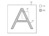
図2は、生成された印刷対象画像を例示する図である。同図に示すように、印刷対象画像は、ハッチングがなされた領域である前景領域18と、前景領域18以外の領域である背景領域20と、を含む。前景領域18は、文字、線、図面、及び写真等の前景に係る領域である。前景領域18に含まれる画素は前景を表す役割を有している。また、背景領域20は、背景に係る領域であり、背景領域20に含まれる画素は背景を表す役割を有している。なお、ここでは、前景領域18に含まれる画素の階調値がすべて「200」であり、背景領域20に含まれる画素の階調値がすべて「100」であるものとする。
FIG. 2 is a diagram illustrating the generated print target image. As shown in the figure, the print target image includes a
点線で囲まれる領域22の意義については後述する。
The significance of the
こうして、印刷対象画像を生成すると、マイクロプロセッサ6は、印刷対象画像をディザ法で二値化することによって、印刷対象画像をディザ法で二値化してなる基準二値画像を生成する。そして、マイクロプロセッサ6は、生成した基準二値画像をメモリ8に保存する。
When the print target image is generated in this way, the
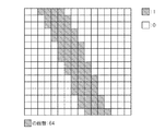
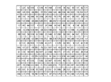
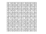
図3は、基準二値画像の一部の領域の画像を例示する図であり、基準二値画像の上記領域22の画像を例示する図である。また、図4は、領域22部分のディザマトリクスを例示する図である。ここで、領域22はタテの長さ及びヨコの長さがともに16画素である領域であり、一つ一つのマスが一つ一つの画素を示している。図4において画素内に記載されている数値は、その画素の二値化に用いる閾値を示している。階調値が閾値より大きい場合、階調値が「1」へと変換され、階調値が閾値以下である場合、階調値が「0」へと変換される。図3では、ハッチングされている画素は階調値が「1」の画素を示し、ハッチングされていない画素は階調値が「0」の画素を示している。
FIG. 3 is a diagram illustrating an image of a partial region of the reference binary image, and is a diagram illustrating an image of the
また、マイクロプロセッサ6は、基準二値画像を生成するだけでなく、印刷対象画像を単一の閾値(ここでは、「128」)で二値化することによって、印刷対象画像を二値化してなる特定二値画像を生成する。そして、マイクロプロセッサ6は、生成した特定二値画像をメモリ8に保存する。
Further, the
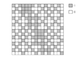
図5は、特定二値画像の一部の領域の画像を例示する図であり、特定二値画像の上記領域22の画像を例示する図である。図5では、前景領域18に含まれる画素の階調値が「1」へと変換され、上記背景領域20に含まれる画素の階調値が「0」へと変換されている。つまり、前景を表す役割を有する画素の階調値が「1」へと変換され、背景を表す役割を有する画素の階調値が「0」へと変換されている。
FIG. 5 is a diagram illustrating an image of a partial region of the specific binary image, and is a diagram illustrating an image of the
[画像処理回路、プリンタエンジン]
基準二値画像と特定二値画像とがメモリ8に格納されると、画像処理回路12は、基準二値画像と特定二値画像とを読み出し、読み出した特定二値画像に基づいて基準二値画像を多値化し、新たに印刷対象画像(以下、新印刷対象画像と記載する)を生成する。また、画像処理回路12は、新印刷対象画像にハーフトーン処理等の各種画像処理を施し、プリンタエンジン14へと出力する。そして、プリンタエンジン14が、新印刷対象画像を印刷出力する。なお、プリンタエンジン14は、画像出力部及び画像形成部などと呼ばれる場合もある。
[Image processing circuit, printer engine]
When the reference binary image and the specific binary image are stored in the memory 8, the
[機能ブロック]
この画像処理システム2では、印刷対象画像の階調値が再現されるように新印刷対象画像の生成が行われるようになっている。以下この点について説明する。
[Function block]
In the
図6は、画像処理システム2にて実現される機能群を示す機能ブロック図である。同図に示すように、画像処理システム2では、印刷対象画像生成部30と、基準二値画像取得部32と、特定二値画像取得部34と、多値化実行部36と、スクリーン処理部38と、出力部40と、が実現される。
FIG. 6 is a functional block diagram showing a function group realized in the
本実施形態の場合、印刷対象画像生成部30、基準二値画像取得部32、及び特定二値画像取得部34は、上記プログラムに従って動作するマイクロプロセッサ6によって実現される。また、多値化実行部36及びスクリーン処理部38は画像処理回路12によって実現される。また、出力部40はプリンタエンジン14によって実現される。なお、多値化実行部36及びスクリーン処理部38は上記プログラムに従って動作するマイクロプロセッサ6によって実現されてもよい。
In the case of the present embodiment, the print target
[印刷対象画像生成部、基準二値画像取得部、特定二値画像取得部]
印刷対象画像生成部30は、多値画像である印刷対象画像を示すビットマップデータを生成する(図2参照)。また、基準二値画像取得部32は、印刷対象画像をディザ法で二値化してなる基準二値画像(図3参照)を取得し、メモリ8に保存する。また、特定二値画像取得部34は、単一の閾値で印刷対象画像を二値化することによって基準二値画像とは異なる画像である特定二値画像(図5参照)を取得し、メモリ8に保存する。
[Print target image generation unit, reference binary image acquisition unit, specific binary image acquisition unit]
The print target
[多値化実行部]
多値化実行部36は、特定二値画像取得部34により取得された特定二値画像に基づいて、基準二値画像取得部32により取得された基準二値画像に含まれる画素それぞれの階調値を多値化する。すなわち、多値化実行部36は、基準二値画像と特定二値画像とをメモリ8から読み出し、特定二値画像に基づいて基準二値画像を多値化することによって新印刷対象画像を生成する。
[Multi-valued execution part]
Based on the specific binary image acquired by the specific binary
より詳しくは、多値化実行部36は、印刷対象画像の階調値が再現されるようにするために、一の画素(以下、注目画素と記載する)の画素値を多値化する場合、以下の処理を実行する。
More specifically, the multi-value
すなわち、多値化実行部36は、まず、注目画素に基づいて、注目画素を含む予め定められた形状の領域を注目領域として設定する。本実施形態の場合、注目領域のタテの長さ及びヨコの長さの双方とも16画素である。また、注目領域は、注目領域における注目画素の位置が定位置になるように設定される。図7に、注目領域における注目画素の位置を示す。ハッチングされている画素が注目画素を示している。
That is, first, the multi-value
また、多値化実行部36は、注目領域に含まれる画素それぞれの種別を、特定二値画像に基づいて特定する。すなわち、多値化実行部36は、注目領域に含まれる画素それぞれが、前景を表す役割を有する画素(以下、前景画素と記載する)であるか又は背景を表す役割を有する画素(以下、背景画素と記載する)であるかを特定する。例えば、ある画素の特定二値画像における階調値が「1」である場合、その画素は前景画素となる。一方、ある画素の特定二値画像における階調値が「0」である場合、その画素は背景画素となる。
Moreover, the multi-value
また、多値化実行部36は、注目領域に含まれる画素のうちの注目画素と同種別の画素、のうちに階調値が「1」の画素が含まれている割合Rに基づいて、注目画素の多値化後の階調値を決定する。
In addition, the multi-value
例えば、領域22(図2参照)が注目領域である場合を例に取り上げる。この場合、特定二値画像(図5参照)における注目画素(図7参照)の階調値が「1」であるので、多値化実行部36は、注目領域のうちで、特定二値画像における階調値が「1」である画素を特定し、特定した画素の数nを計数する。この場合、特定された画素の数nは「64」になる(図5参照)。
For example, a case where the region 22 (see FIG. 2) is a region of interest is taken as an example. In this case, since the gradation value of the pixel of interest (see FIG. 7) in the specific binary image (see FIG. 5) is “1”, the multi-value
また、多値化実行部36は、特定した画素のうちで、基準二値画像(図3参照)における階調値が「1」の画素を特定し、特定した画素の数mを計数する。図8は、特定された画素を示す。ハッチングされている画素が特定された画素を示している。なお、この場合、特定された画素の数mは「51」となる。その結果、上記割合Rは、「51」/「64」となる。
Further, the multi-value
そして、多値化実行部36は、階調値の最大値「255」と割合Rとの積に基づいて、多値化後の注目画素の階調値を決定する。例えば、多値化実行部36は、「255」と割合Rとの積の整数部分である「203」を、多値化後の注目画素の階調値として決定する。その結果、注目画素の階調値が、印刷対象画像における階調値「200」に近い値に設定される。
Then, based on the product of the maximum tone value “255” and the ratio R, the multi-value
多値化実行部36は、以上のようにして基準二値画像に含まれる画素それぞれの階調値を多値化することによって、新印刷対象画像を生成する。この画像処理システム2では、基準二値画像における階調値が「1」の画素が「注目領域に含まれる画素のうちの注目画素と同種別の画素」のうちに含まれる割合(上記R)に基づいて注目画素の画素値が多値化される。そのため、基準二値画像における階調値が「1」の画素が「注目領域に含まれる画素」のうちに含まれる割合に基づいて注目画素の画素値が多値化される場合に比して、多値化の精度が向上するようになる。
The
[スクリーン処理部、出力部]
多値化実行部36により新印刷対象画像のビットマップデータが生成されると、スクリーン処理部38は、ハーフトーン処理などの各種画像処理を新印刷対象画像に施し、出力部40に供給する。そして、出力部40は、新印刷対象画像を印刷出力することになる。
[Screen processing unit, output unit]
When the bitmap data of the new print target image is generated by the multilevel
なお、本発明の実施形態は上記実施形態だけに限らない。 The embodiment of the present invention is not limited to the above embodiment.
例えば、特定二値画像取得部34は、印刷対象画像を単一の閾値で二値化することによって特定二値画像(図5参照)を取得するのに代えて、以下に説明するようにして特定二値画像を取得するようにしてもよい。
For example, instead of acquiring the specific binary image (see FIG. 5) by binarizing the print target image with a single threshold, the specific binary
すなわち、特定二値画像取得部34は、基準二値画像の場合とは異なるディザマトリクス(以下、第1のディザマトリクスと記載する)で印刷対象画像を二値化した第1の特定二値画像と、基準二値画像の場合とは異なるディザマトリクスであって第1のディザマトリクスの閾値配列を一画素ずらしてなる第2のディザマトリクスで印刷対象画像を二値化した第2の特定二値画像と、に基づいて特定二値画像を生成する。
That is, the specific binary
より詳しくは、特定二値画像取得部34は、画素毎に、第1の特定二値画像における階調値と第2の特定二値画像における階調値との論理積を求めることによって、特定二値画像を生成する。その結果、特定二値画像に含まれる任意の画素Xの階調値は、画素Xの第1の特定二値画像における階調値と画素Xの第2の特定二値画像における階調値との論理積になる。
More specifically, the specific binary
図9Aは、第1の特定二値画像の一部の領域の画像を例示する図であり、第1の特定二値画像の上記領域22の画像を例示する図である。図9Bは、第2の特定二値画像の一部の領域の画像を例示する図であり、第2の特定二値画像の上記領域22の画像を例示する図である。ハッチングされている画素は階調値が「1」の画素を示し、ハッチングされていない画素は階調値が「0」の画素を示している。
FIG. 9A is a diagram illustrating an image of a partial region of the first specific binary image, and is a diagram illustrating an image of the
また、図10Aは、第1のディザマトリクスの一部を例示する図であり、第1のディザマトリクスの領域22に対応する部分を例示する図である。また、図10Bは、第2のディザマトリクスの一部を例示する図であり、第2のディザマトリクスの領域22に対応する部分を例示する図である。両図を見ても分かるように、第1のディザマトリクスの閾値配列を右に一画素ずらすと、第2のディザマトリクスとなる。
FIG. 10A is a diagram illustrating a part of the first dither matrix, and is a diagram illustrating a part corresponding to the
第1のディザマトリクスと第2のディザマトリクスとは上述したような関係にあるため、第1の特定二値画像と第2の特定二値画像とから特定二値画像を生成した場合、単一の閾値で印刷対象画像を二値化して特定二値画像を生成する場合と同様の特定二値画像(図5参照)が得られるようになる。そのため、第1の特定二値画像と第2の特定二値画像とから特定二値画像を生成するようにしても、単一の閾値で印刷対象画像を二値化して特定二値画像を生成する場合と同様に、上記前景画素に対して確実に階調値「1」が割り当てられたり、上記背景画素に対して確実に階調値「0」が割り当てられるようになる。そのため、第1の特定二値画像と第2の特定二値画像とから特定二値画像を生成するようにしても、単一の閾値で印刷対象画像を二値化して特定二値画像を生成する場合と同様に、注目領域に含まれる画素それぞれの種別が正確に特定されるようになり、その結果として多値化の精度が向上するようになる。 Since the first dither matrix and the second dither matrix have the relationship as described above, when a specific binary image is generated from the first specific binary image and the second specific binary image, a single dither matrix is generated. A specific binary image (see FIG. 5) similar to the case where the specific binary image is generated by binarizing the print target image with the threshold value of λ is obtained. Therefore, even if the specific binary image is generated from the first specific binary image and the second specific binary image, the print target image is binarized with a single threshold value to generate the specific binary image. As in the case of the above, the gradation value “1” is surely assigned to the foreground pixel, and the gradation value “0” is surely assigned to the background pixel. Therefore, even if the specific binary image is generated from the first specific binary image and the second specific binary image, the print target image is binarized with a single threshold value to generate the specific binary image. As in the case of doing so, the type of each pixel included in the region of interest is accurately specified, and as a result, the accuracy of multi-leveling is improved.
2 画像処理システム、4 ページプリンタ、6 マイクロプロセッサ、8 メモリ、10 通信インタフェース、12 画像処理回路、14 プリンタエンジン、18 前景領域、20 背景領域、22 領域、30 印刷対象画像生成部、32 基準二値画像取得部、34 特定二値画像取得部、36 多値化実行部、38 スクリーン処理部、40 出力部。 2 image processing system, 4 page printer, 6 microprocessor, 8 memory, 10 communication interface, 12 image processing circuit, 14 printer engine, 18 foreground area, 20 background area, 22 area, 30 print target image generation unit, 32 reference 2 A value image acquisition unit, 34 a specific binary image acquisition unit, 36 a multivalue conversion execution unit, a 38 screen processing unit, and an output unit.
Claims (2)
前記原画像を二値化してなる画像であって前記基準二値画像とは異なる画像である特定二値画像、を少なくとも一つ取得する特定二値画像取得手段と、
前記少なくとも一つの特定二値画像に基づいて前記基準二値画像に含まれる画素それぞれの画素値を多値化する多値化手段と、
を含み、
前記多値化手段は、
前記基準二値画像に含まれる画素のうちの一の画素の画素値を多値化する場合、前記一の画素を含む注目領域に含まれる画素それぞれの種別を、前記少なくとも一つの特定二値画像に基づいて複数の種別のうちで特定し、前記注目領域に含まれる画素のうちの前記一の画素と同種別の画素、のうちに予め定められた画素値を有する画素が含まれている割合に基づいて、前記一の画素の多値化後の画素値を決定すること、
を特徴とする画像処理システム。 A reference binary image acquisition means for acquiring a reference binary image obtained by binarizing an original image which is a multi-value image by a dither method;
Specific binary image acquisition means for acquiring at least one specific binary image that is an image obtained by binarizing the original image and is different from the reference binary image;
Multi-value quantization means for multi-value pixel values of each pixel included in the reference binary image based on the at least one specific binary image;
Including
The multi-value conversion means includes
When the pixel value of one of the pixels included in the reference binary image is multi-valued, the type of each pixel included in the region of interest including the one pixel is set as the at least one specific binary image. The ratio of pixels having the predetermined pixel value among the pixels of the same type as the one pixel among the pixels included in the region of interest specified among a plurality of types based on Determining a pixel value after multi-value conversion of the one pixel based on
An image processing system.
前記原画像を二値化してなる画像であって前記基準二値画像とは異なる画像である特定二値画像、を少なくとも一つ取得する特定二値画像取得手段、
前記少なくとも一つの特定二値画像に基づいて前記基準二値画像に含まれる画素それぞれの画素値を多値化する多値化手段、
としてコンピュータを機能させ、
前記多値化手段は、
前記基準二値画像に含まれる画素のうちの一の画素の画素値を多値化する場合、前記一の画素を含む注目領域に含まれる画素それぞれの種別を、前記少なくとも一つの特定二値画像に基づいて複数の種別のうちで特定し、前記注目領域に含まれる画素のうちの前記一の画素と同種別の画素、のうちに予め定められた画素値を有する画素が含まれている割合に基づいて、前記一の画素の多値化後の画素値を決定すること、
を特徴とするプログラム。 A reference binary image acquisition means for acquiring a reference binary image obtained by binarizing an original image which is a multi-valued image by a dither method;
Specific binary image acquisition means for acquiring at least one specific binary image that is an image obtained by binarizing the original image and different from the reference binary image;
Multi-value quantization means for multi-value pixel values of each pixel included in the reference binary image based on the at least one specific binary image;
Function as a computer
The multi-value conversion means includes
When the pixel value of one of the pixels included in the reference binary image is multi-valued, the type of each pixel included in the region of interest including the one pixel is set as the at least one specific binary image. The ratio of pixels having the predetermined pixel value among the pixels of the same type as the one pixel among the pixels included in the region of interest specified among a plurality of types based on Determining a pixel value after multi-value conversion of the one pixel based on
A program characterized by
Priority Applications (1)
| Application Number | Priority Date | Filing Date | Title |
|---|---|---|---|
| JP2010251831A JP2012105065A (en) | 2010-11-10 | 2010-11-10 | Image processing system and program |
Applications Claiming Priority (1)
| Application Number | Priority Date | Filing Date | Title |
|---|---|---|---|
| JP2010251831A JP2012105065A (en) | 2010-11-10 | 2010-11-10 | Image processing system and program |
Publications (1)
| Publication Number | Publication Date |
|---|---|
| JP2012105065A true JP2012105065A (en) | 2012-05-31 |
Family
ID=46394962
Family Applications (1)
| Application Number | Title | Priority Date | Filing Date |
|---|---|---|---|
| JP2010251831A Pending JP2012105065A (en) | 2010-11-10 | 2010-11-10 | Image processing system and program |
Country Status (1)
| Country | Link |
|---|---|
| JP (1) | JP2012105065A (en) |
Cited By (1)
| Publication number | Priority date | Publication date | Assignee | Title |
|---|---|---|---|---|
| EP3200440A1 (en) | 2016-01-28 | 2017-08-02 | Funai Electric Co., Ltd. | Image forming device |
-
2010
- 2010-11-10 JP JP2010251831A patent/JP2012105065A/en active Pending
Cited By (1)
| Publication number | Priority date | Publication date | Assignee | Title |
|---|---|---|---|---|
| EP3200440A1 (en) | 2016-01-28 | 2017-08-02 | Funai Electric Co., Ltd. | Image forming device |
Similar Documents
| Publication | Publication Date | Title |
|---|---|---|
| US8280100B2 (en) | Image processing apparatus, image processing method, and computer program product | |
| JP2009278363A (en) | Image processor and image processing method | |
| US11818319B2 (en) | Information processing apparatus, image processing method, and medium | |
| JP2010161503A (en) | Image forming apparatus and image forming method | |
| JP6029305B2 (en) | Image processing apparatus and control method thereof | |
| JP5893379B2 (en) | Image compression apparatus, image compression method, and computer program | |
| US8014030B2 (en) | Image processing and formation with line thininng by reducing intensity of target pixel based on extracted contour pixel and area connectedness information | |
| JP4525916B2 (en) | Image forming apparatus, image forming method, image processing apparatus, and image processing method | |
| JP2012105065A (en) | Image processing system and program | |
| JP5747570B2 (en) | Printing apparatus and printing method | |
| US7502145B2 (en) | Systems and methods for improved line edge quality | |
| JP4656457B2 (en) | Image processing system | |
| JP5915410B2 (en) | Image processing apparatus and program | |
| JP7185451B2 (en) | Image processing device, image processing method, and program | |
| JP5337060B2 (en) | Image processing apparatus, control method, and program | |
| JP2012231261A (en) | Image processing apparatus and control method thereof | |
| JP5457853B2 (en) | Image encoding apparatus, image encoding method, program, and storage medium | |
| JP6413783B2 (en) | Printing instruction apparatus, printing system, and program | |
| JP2008283269A (en) | Image processing device and image processing method | |
| JP2006261764A (en) | Image processing method and apparatus, and image forming apparatus | |
| JP2008278462A (en) | Image processing device, image processing method, and storage medium | |
| JP2008052588A (en) | Program, information storage medium, two-dimensional code generation system and two-dimensional code | |
| JP2007036471A (en) | Image processing method and image processing apparatus | |
| JP5337059B2 (en) | Image processing apparatus, control method, and program | |
| JP2011166765A (en) | Image forming device and image forming method |