JP5893379B2 - Image compression apparatus, image compression method, and computer program - Google Patents
Image compression apparatus, image compression method, and computer program Download PDFInfo
- Publication number
- JP5893379B2 JP5893379B2 JP2011272157A JP2011272157A JP5893379B2 JP 5893379 B2 JP5893379 B2 JP 5893379B2 JP 2011272157 A JP2011272157 A JP 2011272157A JP 2011272157 A JP2011272157 A JP 2011272157A JP 5893379 B2 JP5893379 B2 JP 5893379B2
- Authority
- JP
- Japan
- Prior art keywords
- image
- resolution
- reduction
- reduced
- unit
- Prior art date
- Legal status (The legal status is an assumption and is not a legal conclusion. Google has not performed a legal analysis and makes no representation as to the accuracy of the status listed.)
- Expired - Fee Related
Links
- 230000006835 compression Effects 0.000 title claims description 52
- 238000007906 compression Methods 0.000 title claims description 52
- 238000000034 method Methods 0.000 title claims description 37
- 238000004590 computer program Methods 0.000 title claims description 4
- 238000006243 chemical reaction Methods 0.000 description 16
- 239000003086 colorant Substances 0.000 description 11
- 238000010586 diagram Methods 0.000 description 10
- 238000000605 extraction Methods 0.000 description 9
- 230000006837 decompression Effects 0.000 description 7
- 230000006870 function Effects 0.000 description 5
- 238000009826 distribution Methods 0.000 description 4
- 238000005429 filling process Methods 0.000 description 4
- 238000003860 storage Methods 0.000 description 4
- 238000004364 calculation method Methods 0.000 description 2
- 238000011946 reduction process Methods 0.000 description 2
- 241000255925 Diptera Species 0.000 description 1
- 230000015556 catabolic process Effects 0.000 description 1
- 238000004891 communication Methods 0.000 description 1
- 238000005520 cutting process Methods 0.000 description 1
- 238000006731 degradation reaction Methods 0.000 description 1
- 230000006866 deterioration Effects 0.000 description 1
- 239000000284 extract Substances 0.000 description 1
- 230000014509 gene expression Effects 0.000 description 1
- 238000002372 labelling Methods 0.000 description 1
- 238000007591 painting process Methods 0.000 description 1
- 230000002093 peripheral effect Effects 0.000 description 1
- 238000009877 rendering Methods 0.000 description 1
- 230000004044 response Effects 0.000 description 1
- 230000001360 synchronised effect Effects 0.000 description 1
- 230000002194 synthesizing effect Effects 0.000 description 1
Images


Classifications
-
- G—PHYSICS
- G06—COMPUTING; CALCULATING OR COUNTING
- G06T—IMAGE DATA PROCESSING OR GENERATION, IN GENERAL
- G06T9/00—Image coding
-
- H—ELECTRICITY
- H04—ELECTRIC COMMUNICATION TECHNIQUE
- H04N—PICTORIAL COMMUNICATION, e.g. TELEVISION
- H04N19/00—Methods or arrangements for coding, decoding, compressing or decompressing digital video signals
-
- H—ELECTRICITY
- H04—ELECTRIC COMMUNICATION TECHNIQUE
- H04N—PICTORIAL COMMUNICATION, e.g. TELEVISION
- H04N19/00—Methods or arrangements for coding, decoding, compressing or decompressing digital video signals
- H04N19/20—Methods or arrangements for coding, decoding, compressing or decompressing digital video signals using video object coding
- H04N19/27—Methods or arrangements for coding, decoding, compressing or decompressing digital video signals using video object coding involving both synthetic and natural picture components, e.g. synthetic natural hybrid coding [SNHC]
-
- H—ELECTRICITY
- H04—ELECTRIC COMMUNICATION TECHNIQUE
- H04N—PICTORIAL COMMUNICATION, e.g. TELEVISION
- H04N19/00—Methods or arrangements for coding, decoding, compressing or decompressing digital video signals
- H04N19/50—Methods or arrangements for coding, decoding, compressing or decompressing digital video signals using predictive coding
- H04N19/59—Methods or arrangements for coding, decoding, compressing or decompressing digital video signals using predictive coding involving spatial sub-sampling or interpolation, e.g. alteration of picture size or resolution
-
- G—PHYSICS
- G06—COMPUTING; CALCULATING OR COUNTING
- G06V—IMAGE OR VIDEO RECOGNITION OR UNDERSTANDING
- G06V30/00—Character recognition; Recognising digital ink; Document-oriented image-based pattern recognition
- G06V30/10—Character recognition
Description
本発明は、入力された多値画像を圧縮する画像圧縮技術に関するものである。 The present invention relates to an image compression technique for compressing an input multilevel image.
近年、スキャナの普及により、紙文書の電子化が進んでいる。一般に、カラー画像はファイルサイズが大きいため、現在、JPEG圧縮などを行って画像を圧縮する方法が普及している。しかしながら、JPEG圧縮は写真などの自然画像を圧縮するには非常に効果的だが、文字部をJPEG圧縮するとモスキートノイズと呼ばれる画像劣化が発生する。そのため、特許文献1及び特許文献2に示されるような方法が提案されている。この方法では、入力された画像を文字領域、写真領域及び背景領域に領域分割を行い、文字領域部分は2値化した上でMMR圧縮、背景領域部分はJPEG圧縮を行うことで、文字領域の品位を保ったまま、フルカラー画像も小さなファイルサイズで表現する。
In recent years, with the widespread use of scanners, paper documents have been digitized. In general, since a color image has a large file size, a method of compressing an image by performing JPEG compression or the like is now widespread. However, JPEG compression is very effective for compressing natural images such as photographs. However, when the character portion is JPEG compressed, image degradation called mosquito noise occurs. Therefore, methods as shown in Patent Document 1 and
特許文献1、2よりも更に大幅なファイルサイズの削減を行うためには、背景領域を大幅に縮小することが考えられる。例えば、入力画像が300dpiの場合、背景領域を50dpiや25dpiに縮小することでファイルサイズを大きく削減することができる。背景領域の内容があまり重要でない場合には、このように背景領域の解像度を大幅に小さく(25dpiなど)することは有用であると考えられる。しかし、特許文献1に記載されるように、文字の代表色抽出前に入力画像を大幅に縮小(低解像度化)してしまうと、50dpiや25dpiの縮小多値画像を使って代表色抽出を行うことになってしまい、適切な各文字代表色を抽出できないという課題があった。適切な各文字代表色を抽出できない理由としては、入力画像300dpiにおける縦横12×12画素の色が、縮小多値画像25dpiにおける1画素の色にまとめられてしまい、文字色とその他の背景などの色が混色してしまうことがあげられる。すなわち、12×12画素の色が複数の色で構成される場合は、1つの色にまとめられることで色情報が大きく欠落してしまう。
また、特許文献2に記載されるように、JPEG圧縮の直前で低解像度化する場合は、低解像度化前のカラー多値画像を用いて適切な各文字代表色を求めることは可能である。しかしながら、代表色抽出処理を行う際に、低解像度化前のカラー多値画像を一時的に格納するための多大なメモリ容量が必要である。例えば、300dpi/RGB24bitのカラー多値画像の場合、24Mbyteのメモリ容量が必要である。従って、メモリ容量が少ない画像圧縮装置においては実現できず、また、メモリ容量を増やす場合は、ハードウェアの大幅なコストアップになってしまうという課題がある。
In order to further reduce the file size much more than in
As described in
上記課題を解決するために、本発明の画像圧縮装置は、ユーザから解像度に関する指定を受け付ける受付手段と、画像を入力する入力手段と、前記入力された画像の解像度を、前記受け付けた指定に基づく解像度よりも高い所定の解像度へと低下させる第1の低下手段と、前記入力された画像を当該画像の解像度を低下させずに解析することで、前記第1の低下手段により解像度が低下させられた画像における文字領域を特定する特定手段と、前記特定手段により特定された前記第1の低下手段により解像度が低下させられた画像における前記文字領域の色を、当該文字領域以外の領域の色を用いて変更する変更手段と、前記文字領域の色が変更された画像の解像度を、前記受け付けた指定に基づく解像度および前記所定の解像度の解像度比に従って、前記受け付けた指定に基づく解像度へと低下させる第2の低下手段と、前記第2の低下手段により解像度が低下させられた画像を圧縮する圧縮手段とを有することを有することを特徴とする。 In order to solve the above problems, an image compression apparatus according to the present invention is based on a receiving unit that receives a designation regarding resolution from a user, an input unit that inputs an image, and a resolution of the input image based on the received designation. The first reduction means for reducing the resolution to a predetermined resolution higher than the resolution, and analyzing the input image without reducing the resolution of the image, the resolution is reduced by the first reduction means. Specifying means for specifying the character area in the image, and the color of the character area in the image whose resolution is reduced by the first reducing means specified by the specifying means, and the color of the area other than the character area A changing unit that changes the color of the character region using a resolution based on the received designation and a resolution ratio of the predetermined resolution. Thus, and having to have a compression means for compressing the second reduction means for reducing to a resolution based on the specified that the accepted, the image resolution has been reduced by the second reduction means .
(実施例1)
以下、本発明を実施するための最良の形態について図面を用いて説明する。尚、以下に説明する実施例の画像圧縮装置及び画像伸長装置の各構成要素の相対配置、各処理に用いられる数式、数値等は、特に、特定的な記載がない限りは、この発明の範囲をそれらのみに限定する趣旨のものではない。
Example 1
The best mode for carrying out the present invention will be described below with reference to the drawings. It should be noted that the relative arrangement of each component of the image compression apparatus and the image expansion apparatus according to the embodiments described below, mathematical expressions, numerical values, and the like used for each process are within the scope of the present invention unless otherwise specified. It is not intended to limit only to those.
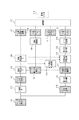
図1は本実施例の画像圧縮装置の概略構成を示す図である。図1において、実線は画像の流れ及び入力を示し、点線は情報の流れ及び入力を示すものとする。入力画像101は、カラー多値画像であり、本実施例では、300dpi/RGB24bitとする。2値化部102は入力画像101を2値化して、2値画像103を生成する。領域特定部A104は、2値画像103を入力とし、例えば、所定値をとる画素(例えば、黒画素)の輪郭線追跡やラベリング処理等により文字領域を検出して、文字領域座標106を作成する。文字領域座標106は、文字領域の位置(座標)やサイズを示す情報である。また、領域特定部A104が文字領域を特定することで、それ以外の写真やイラスト等の自然(階調)画像を示す自然画像領域の位置やサイズも特定されることは言うまでもない。更に、各領域の種類を特定するための属性情報(文字や画像)も別途生成する。なお、文字や画像の属性判別は黒連結画素の大きさ・位置・画素密度等などに基づき公知の技術により識別できる。領域特定部B105は、2値画像103と領域特定部A104により作成された文字領域座標106を入力とし、文字領域内における各文字(単位文字領域)の位置及びサイズを特定する。説明を簡単にするため、実施例1では、各単位文字領域の位置及びサイズの情報も文字領域座標106に追加するものとする。また、領域特定部A104により作成された文字領域座標106により、文字領域毎の2値画像(部分2値画像107)を作成する。
FIG. 1 is a diagram showing a schematic configuration of an image compression apparatus according to the present embodiment. In FIG. 1, a solid line indicates an image flow and input, and a dotted line indicates an information flow and input. The
また、第一の縮小部113は、多値画像112を縮小(低解像度化)して、縮小多値画像114(第1の縮小多値画像)を生成する。ここで、第一の縮小部113における縮小率は、縮小多値画像114を格納するために使用可能なRAM206のメモリ容量にもとづいて決定される。第一の縮小部113における縮小率の詳細については後述する。尚、多値画像112は入力画像101と同一である。
The
代表色抽出部110は、部分2値画像107と文字領域座標106及び縮小多値画像114を入力・参照し、部分2値画像107の黒部分と縮小多値画像114とを位置対応させながら、文字領域中の各単位文字領域の各文字代表色111を算出する。
The representative
文字領域穴埋め部115は、部分2値画像107と縮小多値画像114及び文字領域座標106を入力・参照し、縮小多値画像114上の各文字領域あるいは単位文字領域毎に、その周辺色で塗り潰す処理を行う。すなわち、文字の画素値をその周辺色(周辺の背景色)で置換することによって、縮小多値画像における文字部分の穴埋め処理を行う。
The character
第二の縮小部119は、文字領域穴埋め部115で文字領域をその周辺色で塗り潰した後の縮小多値画像に対して第二の縮小処理を行うことにより、第2の縮小多値画像を生成する。ここで、第二の縮小部119における縮小率は、操作部203に表示される画面上で選択された情報にもとづいて決定される。第二の縮小部119における縮小率の詳細については後述する。
The
JPEG圧縮部116は、文字領域穴埋め部115において穴埋めされ且つ第二の縮小部で縮小された穴埋め後縮小多値画像(第2の縮小多値画像)を、JPEG圧縮して圧縮コードB117(第1の圧縮コード)を生成する。
The
また、MMR圧縮部108は、部分2値画像107のそれぞれをMMR圧縮して、圧縮コードA109(第2の圧縮コード)を生成する。なお、MMR圧縮部108の代わりに、MMR圧縮以外の2値画像圧縮、例えば、JBIG圧縮、MR圧縮、MH圧縮等を用いても良い。
Further, the
合成部120は、文字領域座標106、圧縮コードA109、各文字代表色111、圧縮コードB117のデータ群を合成し、圧縮データ118を出力する。この圧縮データ118を、更に、PDFなどに可逆圧縮しても良い。
The synthesizing
尚、入力画像101中に文字領域が存在しない場合、圧縮データ118は圧縮コードB117のみとなる。
If there is no character area in the
また、図1の画像圧縮装置を実現するハードウェア構成としては、例えば、パーソナルコンピュータ等の汎用コンピュータを用いて実現できる。また、この汎用コンピュータには、その標準的な構成要素として、例えば、CPU、RAM、ROM、ハードディスク、外部記憶装置、ネットワークインタフェース、ディスプレイ、キーボード、マウス等を有している。すなわち、コンピュータ読み取り可能な記憶媒体に格納されたコンピュータプログラムは、コンピュータを、後述するフローチャートの処理を実行する図1の各処理部として機能させる。なお、生成された圧縮データを伸長する画像伸長装置(後述)も同様のハードウェア構成を用いて実現できる。また、これらの画像圧縮装置及び画像伸長装置は、汎用コンピュータに対する拡張カードとして実現される専用ハードウェアとして実現されても良い。 The hardware configuration for realizing the image compression apparatus in FIG. 1 can be realized by using a general-purpose computer such as a personal computer, for example. The general-purpose computer has, for example, a CPU, a RAM, a ROM, a hard disk, an external storage device, a network interface, a display, a keyboard, and a mouse as standard components. That is, the computer program stored in the computer-readable storage medium causes the computer to function as each processing unit in FIG. 1 that executes the processing of the flowchart described later. Note that an image decompression device (described later) that decompresses the generated compressed data can also be realized using the same hardware configuration. Further, these image compression apparatus and image expansion apparatus may be realized as dedicated hardware that is realized as an expansion card for a general-purpose computer.
また、本発明は汎用コンピュータを用いて実現するものに限らない。例えば、ネットワーク通信機能を有する画像処理装置(MFP)、カラースキャナ、カラーファクシミリ等が挙げられる。 Further, the present invention is not limited to that realized using a general-purpose computer. For example, an image processing apparatus (MFP) having a network communication function, a color scanner, a color facsimile, and the like can be given.
次に、本実施例における画像圧縮装置(及び画像伸長装置)を搭載する装置の一例として画像処理装置(MFP)について説明する。図2は画像処理装置(MFP)の詳細構成を示す図である。MFPは、画像入力デバイスであるスキャナ部201、画像出力デバイスであるプリンタ部202、制御ユニット204、ユーザーインタフェースである操作部203等を有する。制御ユニット204は、スキャナ部201、プリンタ部202、操作部203と接続し、一方では、LAN209と接続することで、画像情報やデバイス情報の入出力を行うコントローラである。CPU205はシステム全体を制御する。RAM206はCPU205が動作するためのシステムワークメモリであり、画像データを一時記憶するための画像メモリでもある。ROM210はブートROMであり、システムのブートプログラム等のプログラムが格納されている。記憶部211はハードディスクドライブで、システム制御ソフトウェア、画像データを格納する。操作部I/F207は操作部(UI)203とのインターフェース部で、操作部203に表示するための画像データを操作部203に対して出力する。また、操作部I/F207は操作部203から本画像処理装置の使用者が入力した情報を、CPU205に伝える役割をする。ネットワークIF208は本画像処理装置をLAN209に接続し、パケット形式の情報の入出力を行う。以上のデバイスがシステムバス216上に配置される。イメージバスインターフェース212はシステムバス216と画像データを高速で転送する画像バス217とを接続し、データ構造を変換するバスブリッジである。画像バス217は、例えば、PCIバスやIEEE1394で構成される。画像バス217上には以下のデバイスが配置される。ラスターイメージプロセッサ(RIP)213はPDL(ページ記述言語)コードを解析し、指定された解像度のビットマップイメージに展開する、いわゆるレンダリング処理を実現する。デバイスI/F部214は、信号線218を介して画像入力デバイスであるスキャナ部201、信号線219を介して画像出力デバイスであるプリンタ部202、をそれぞれ制御ユニット204に接続し、画像データの同期系/非同期系の変換を行う。データ処理部215は、図1で述べた画像圧縮装置(または後述する画像伸長装置)として機能する。
Next, an image processing apparatus (MFP) will be described as an example of an apparatus in which the image compression apparatus (and image expansion apparatus) in the present embodiment is mounted. FIG. 2 is a diagram showing a detailed configuration of the image processing apparatus (MFP). The MFP includes a
尚、本実施例では、図2のCPU205がROM210、またはRAM206に格納されたコンピュータプログラムを読み取り実行することによって、データ処理部215(図1の各処理部)として機能するようにしても構わない。また、これに限るものではなく、データ処理部215を、電子回路等のハードウェアで実現するように構成してもよい。
In this embodiment, the
次に、2値化部102が実行する2値化処理について、図3、図7を用いて説明する。図7は本実施例の入力画像の一例を示す図である。また、図3は本実施例の2値化部102が実行する2値化処理を示すフローチャートである。図7において、入力画像701はカラー多値画像であり、702は、領域702の文字は赤色、領域703、704の文字は黒色、領域705、706の画像は任意の複数色であるとする。尚、この入力画像701が図2のスキャナ部201で読み取ったものである場合には、その読取時のバラツキやJPEG圧縮の劣化を含んでいるものとするが、劣化を含んでいない画像も本実施例の対象であることは言うまでもない。 以下では、例として、紙文書をスキャナ部201で読み取った画像を入力画像101(300dpi/RGB24bit)とする場合について説明する。
Next, the binarization process executed by the
まず、ステップS301にて、2値化部102は、入力画像101(RGB画像)を入力とし、次の変換式により輝度変換を行い、輝度画像を生成する。
First, in step S301, the
Y = 0.299×R + 0.587×G + 0.114×B
ステップS302にて、2値化部102は、ステップS301にて生成された輝度画像の全面ヒストグラムを作成する。ここで、ヒストグラムの一例を図示すると図4のようになる。図4において、横軸はY信号の輝度レベル0〜255であり、縦軸はその出現頻度を示している。図4の場合、401が文字や画像の分布であり、402が下地の分布であることを示している。
Y = 0.299 × R + 0.587 × G + 0.114 × B
In step S302, the
ステップS303にて、2値化部102は、最適な2値化閾値Tを算出する。但し、ここでの2値化閾値Tの算出方法は、特に限定はしない。図4では、例えば、分布401と分布402の頂点の輝度レベル間の中間点403を2値化閾値Tとしている。
In step S303, the
ステップS304にて、2値化部102は、輝度画像を2値化閾値Tに基づいて、2値化して2値画像を生成する。以上の処理により、図1の2値画像103が作成される。例えば、図7の多値画像701を2値化した場合の2値画像は、図7の2値画像707のようになる。
In step S304, the
次に、領域特定部A104が実行する処理について説明する。領域特定部A104は、2値画像103を入力として、黒画素を参照しながら、輪郭線追跡を行う。次に、追跡された輪郭線内をさらに追跡し、その追跡結果に基づいて、輪郭線内の領域から文字領域と、その位置やサイズを特定する。尚、文字領域以外の領域は、背景領域として特定され、背景領域は、写真領域(または、自然画像領域)を含むものとする。
Next, processing executed by the area specifying unit A104 will be described. The area specifying unit A104 receives the
以上の処理により、文字領域、写真領域の位置、サイズ及びその領域の種類を示す属性が特定される。図7の2値画像707の例では、708〜710は、文字領域として特定され、711、712は、写真領域として特定される。前述したように背景領域は、文字領域以外の領域であり、写真領域を含む。
With the above processing, the attributes indicating the position and size of the character region and the photo region and the type of the region are specified. In the example of the
次に、領域特定部B105が実行する処理について説明する。領域特定部B105は、領域特定部A104により特定された各文字領域に対して順に処理を行う。具体的には、各文字領域に対して2値画像の所定値(黒画素)をとる画素の集合を単位文字とみなし、単位文字領域の位置を特定する。 Next, processing executed by the area specifying unit B105 will be described. The area specifying unit B105 sequentially processes each character area specified by the area specifying unit A104. Specifically, a set of pixels taking a predetermined value (black pixel) of the binary image for each character area is regarded as a unit character, and the position of the unit character area is specified.
以上のようにして、領域特定部A104及び領域特定部B105により特定された文字領域・単位文字領域の領域情報(位置、サイズ)を、文字領域座標106として、図2の
RAM206に保存する。
As described above, the area information (position and size) of the character area / unit character area specified by the area specifying unit A104 and the area specifying unit B105 is stored in the
次に、第一の縮小部113が実行する処理について説明する。第一の縮小部113は、多値画像112を入力として縮小を行い、縮小多値画像114を生成する。生成された縮小多値画像114は、RAM206に一時的に格納する。本実施例では、縮小とは、低解像度への解像度変換を意味しており、例えばバイキュービック法による解像度変換を行うものとする。また、縮小部113の縮小率は、縮小多値画像114を格納するために使用可能なRAM206のメモリ容量から決定される。
Next, processing executed by the
図6は、縮小多値画像114を格納するために使用可能なRAM206のメモリ容量と第一の縮小部の縮小率の関係を示す図である。尚、多値画像112は300dpi/RGB24bit(24Mbyte)とする。
FIG. 6 is a diagram showing the relationship between the memory capacity of the
例えば、縮小多値画像114を格納するために使用可能なRAM206のメモリ容量が24Mbyte以上である場合、多値画像112は、縮小部113で縮小しなくても格納可能である。この場合、縮小率を100%(縮小しない)とする。
For example, when the memory capacity of the
また、縮小多値画像114を格納するために使用可能なRAM206のメモリ容量が6Mbyte以上24Mbyte未満である場合は、縮小率を50%とする。ここで、縮小率を50%とすると、縮小前の多値画像112(24Mbyte)と比較して必要なメモリ容量を1/4に軽減可能であるため、縮小多値画像114を格納するために必要なメモリは6Mbyteとなる。
When the memory capacity of the
尚、図6では説明を簡単にするために、使用可能なRAM206のメモリ容量が24Mbyte以上の場合と、6Mbyte以上24Mbyte未満の場合の2通りに分けているがこれに限るものではない。例えば、使用可能なRAM206のメモリ容量が14Mbyte以上の場合は、縮小率を75%としてもよい。
In FIG. 6, in order to simplify the description, the
第一の縮小部113における縮小率が極端に低い(例えば、12.5%)と、後述する代表色抽出部110で縮小多値画像114の色情報を参照する際に適切な各文字代表色111を抽出できないという問題が生じる。このため、本実施例では、6Mbyte以上のメモリ容量はあるものとして、第一の縮小部113における最小の縮小率を50%としている。
If the reduction ratio in the
また、本実施例1では縮小多値画像114をRAM206に格納する際は非圧縮で格納しているが圧縮して格納してもよい。
In the first embodiment, when the reduced multi-value image 114 is stored in the
以上のようにして、第一の縮小部113は、縮小多値画像114を格納するために使用可能なRAM206のメモリ容量にもとづいて、縮小率を決定し、縮小多値画像114を生成する。
As described above, the
次に、代表色抽出部110が実行する処理について説明する。代表色抽出部110は、文字領域座標106を参照し、部分2値画像107の黒画素部分と、縮小多値画像114とを位置対応させながら、文字領域中の各単位文字領域の各文字代表色111を抽出する。ここで、部分2値画像107は、2値画像103の文字領域を文字領域座標106にもとづいて切り抜きした画像(文字領域の2値画像)であり、RAM206に格納されている。以上のようにして、各単位文字領域の各文字代表色抽出が行われる。
Next, processing executed by the representative
次に、文字領域穴埋め部115が実行する処理について説明する。文字領域穴埋め部115は、文字領域座標106と部分2値画像107及び縮小多値画像114を入力とし、まず、部分2値画像107の白画素に位置的に対応する縮小多値画像114の色を参照することにより、文字領域内の背景色の平均値を算出する。次に、算出した背景色の平均値を縮小多値画像114の文字領域に割り当てる処理を行う。つまり、縮小多値画像114の文字領域の画素値あるいはその文字領域内の単位文字領域の画素値を、当該算出した背景色で置換(縮小多値画像114における文字画素を背景色で塗り潰す穴埋め処理)し、穴埋め縮小多値画像を生成する。これにより、後のJPEG圧縮部116の圧縮率が向上する。
Next, processing executed by the character
次に、第二の縮小部119が実行する処理について説明する。第二の縮小部119は、
文字領域穴埋め部115によって穴埋めされた画像を入力とし、本画像圧縮装置を使用する使用者(以下、使用者)によって設定された背景の解像度、及び第一の縮小部の縮小率に基づいて縮小率を決定し、縮小を行う。ここで、第二の縮小部の縮小率(%)は、次の計算式により求められる。
Next, processing executed by the
An image filled by the character
第二の縮小部の縮小率(%)={設定された背景の解像度/(多値画像112の解像度×第一の縮小部の縮小率(%)/100)}×100
図5(A)は、本実施例1において、操作部203に表示される解像度の設定を行うための画面の一例である。使用者は、当該設定画面で背景の解像度として150、100、50、25dpiのいずれかを選択する。ここで背景の解像度とは、第二の縮小部119によって縮小する画像の解像度を示す。
Reduction ratio (%) of second reduction part = {set background resolution / (resolution of
FIG. 5A is an example of a screen for setting the resolution displayed on the
図10は、使用者によって設定された背景の解像度と、第一の縮小部の縮小率と、第二の縮小部の縮小率との関係を示す図である。尚、多値画像112は300dpi/RGB24bit(24Mbyte)とする。第一の縮小部の縮小率は前述したように、縮小多値画像114を格納するために使用可能なRAM206のメモリ容量から決定される。
FIG. 10 is a diagram illustrating the relationship among the background resolution, the reduction ratio of the first reduction unit, and the reduction rate of the second reduction unit set by the user. The
例えば、使用者が背景の解像度を150dpiと設定し、第一の縮小部の縮小率が100%の場合、縮小多値画像114の解像度は300dpiであるため、第二の縮小部の縮小率は50%(150÷300×100=50%)と決定される。 For example, when the user sets the background resolution to 150 dpi and the reduction ratio of the first reduction unit is 100%, the resolution of the reduced multilevel image 114 is 300 dpi, so the reduction rate of the second reduction unit is 50% (150 ÷ 300 × 100 = 50%) is determined.
また、使用者が背景の解像度を25dpiと設定し、第一の縮小部の縮小率が50%の場合、縮小多値画像114の解像度は150dpiであるため、第二の縮小部の縮小率は17%(25÷150×100≒17%)と決定される。 When the user sets the background resolution to 25 dpi and the reduction ratio of the first reduction part is 50%, the reduction of the second reduction part is 150 dpi because the resolution of the reduced multilevel image 114 is 150 dpi. 17% (25 ÷ 150 × 100≈17%) is determined.
以上のようにして、第二の縮小部119は、使用者によって設定された背景の解像度、及び第一の縮小部の縮小率にもとづいて縮小率を決定し、縮小を行う。
As described above, the
次に、上述した画像圧縮装置で圧縮された圧縮データ118を伸長する画像伸長装置について、図12を用いて説明する。図12は本実施例の画像伸長装置の概略構成を示す図である。
Next, an image decompression apparatus that decompresses the
抽出部1208は、圧縮データ118から、文字領域座標106、圧縮コードA109、圧縮コードB117、各文字代表色111を抽出する。MMR伸長部1201は、圧縮コードA109に対してMMR伸長処理を行い、2値画像1202を作成する。JPEG伸長部1203は、圧縮コードB117に対してJPEG伸長処理を行い、さらに拡大部1204で元の解像度への拡大処理を行うことで、多値画像1205を作成する。合成部1206は、文字領域座標106を参照しながら、各文字代表色111を2値画像1202中の対応する単位文字領域の各黒画素に割り当て、その2値画像を多値画像1205の上に表示する。この際、2値画像1202の白画素は透明な画素として扱うことで、多値画像1205を透過する。以上のように、図12の画像伸長装置は、図1の画像圧縮装置により作成された圧縮データ118を伸長し、最終的な復元画像である伸長画像1207を生成することができる。
The
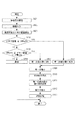
次に、入力画像101が、第一の縮小部113、及び第二の縮小部119において縮小されて、JPEG圧縮部116において圧縮されるまでの処理を図8のフローチャートに示す。
Next, a process until the
まず、ステップS801にて、使用者から背景の解像度の選択を受け付けた操作部203は、その受け付けた背景解像度の情報(解像度情報)をデータ処理部215に送信する。当該設定された背景解像度の情報は、データ処理部215内の第二の縮小部119に送られる。
First, in step S <b> 801, the
ステップS802にて、スキャナ部201は、紙文書を読取り、入力画像101を生成する。ステップS803にて、CPU205は、使用可能なRAM206のメモリ容量を算出する。
In step S <b> 802, the
ステップS804にて、第一の縮小部113は、ステップS803において算出された使用可能なメモリ容量が24Mbyte以上か否かを判断する。24Mbyte以上の場合、ステップS806へ進み、縮小率=100%を設定する。24Mbyte未満の場合、ステップS805へ進み、6Mbyte以上か否かを判断する。6Mbyte以上の場合、ステップS807へ進み、縮小率=50%を設定する。6Mbyte未満の場合、ステップS808へ進み、第一の縮小部113はメモリが不足している旨を操作部203へ通知し、終了する。
In step S804, the
ステップS809にて、第一の縮小部113は、ステップS806またはS807において設定された縮小率を用いて、多値画像112の縮小を行い、縮小多値画像114を生成する。生成された縮小多値画像114は、RAM206に一時的に格納する。
In step S809, the
ステップS810にて、文字領域穴埋め部115は、ステップS809で縮小された縮小多値画像114と、文字領域座標106と、部分2値画像107とを用いて穴埋め処理(文字画素の画素値の置換処理)を行う。ここでは、まず、部分2値画像107の白画素に位置的に対応する縮小多値画像114の色を参照することにより、文字領域内の背景色の平均値を算出する。次に、算出した背景色の平均値を縮小多値画像114の文字領域に割り当てる、つまり、算出した背景色で縮小多値画像114の文字領域あるいはその文字領域内の単位文字領域を穴埋めする。
In step S810, the character
ステップS811にて、第二の縮小部119は、使用者によって設定された背景の解像度、及び第一の縮小部の縮小率にもとづいて縮小率を決定する。
In step S811, the
ステップS812にて、第二の縮小部119は、ステップS811で決定された縮小率を用いて、ステップS810で穴埋めされた縮小多値画像の縮小処理を行う。
In step S812, the
ステップS813にて、JPEG圧縮部116は、ステップS812において縮小された画像に対してJPEG圧縮を行い、圧縮コードB117を生成する。
In step S813, the
以上、説明したように、本実施例1では、第一の縮小部において、使用可能なRAM206のメモリ容量にもとづいて多値画像を縮小し、当該縮小された縮小多値画像を用いて代表色を抽出する。その後、文字領域の穴埋め処理を行い、更に、第二の縮小部において、使用者によって設定された背景の解像度と第一の縮小部の縮小率にもとづいて縮小率を決定し、穴埋め処理された縮小多値画像を更に縮小する。したがって、代表色抽出部で適切な各文字代表色111を抽出しつつ、従来と比較してファイルサイズを大幅に減らすことが可能となる。また、大容量メモリを使えない画像圧縮装置でも実現できる。
As described above, in the first embodiment, the first reduction unit reduces the multi-valued image based on the usable memory capacity of the
尚、本実施例1では、前述したように、図8のステップS803で画像入力後に使用可能なメモリ容量を算出する説明を行ったが、画像の入力前に算出してもよいし、画像処理装置(MFP)毎に予め決められていてもよい。 In the first embodiment, as described above, the description has been given of calculating the usable memory capacity after inputting an image in step S803 in FIG. 8, but it may be calculated before inputting an image or may be performed by image processing. It may be predetermined for each apparatus (MFP).
(実施例2)
実施例1の第二の縮小部は、使用者によって設定された背景の解像度と、第一の縮小部の縮小率にもとづいて縮小率を決定して、縮小を行っていた。実施例2では、使用者が背景の解像度を直接指定するのではなく、図5(B)に示すような操作部203に表示される設定画面で画質、及びファイルサイズを指定する場合について説明する。これにより、使用者は背景の解像度などの情報を意識することなく目的に応じたデータ生成が可能となる。
(Example 2)
The second reduction unit according to the first exemplary embodiment performs reduction by determining the reduction rate based on the background resolution set by the user and the reduction rate of the first reduction unit. In the second embodiment, a case where the user does not directly specify the background resolution but specifies the image quality and the file size on the setting screen displayed on the
図5(B)は、操作部203に表示される設定画面の一例である。使用者は、当該設定画面で画質及びファイルサイズとして、「最高画質」、「画質優先」、「サイズ優先」、「お任せ」のいずれかを選択する。
FIG. 5B is an example of a setting screen displayed on the
次に、当該設定画面で設定された内容にもとづいて、入力画像101(300dpi)が、第一の縮小部113、及び第二の縮小部119において縮小されて、JPEG圧縮部116において圧縮されるまでの処理を図9のフローチャートに示す。尚、実施例1における図8で前述した処理と同じである場合、図8と同じステップ番号を用いる。
Next, based on the content set on the setting screen, the input image 101 (300 dpi) is reduced by the
まず、ステップS901にて、使用者から図5(B)で前述した選択を受け付けた操作部203は、その受け付けた旨、即ち「最高画質」、「画質優先」、「サイズ優先」、「お任せ」のいずれが選択されているかの情報をデータ処理部215に送信する。その旨を受け付けたデータ処理部215は、第一の縮小部113の縮小率、及び第二の縮小部119の縮小率の設定を行うために、第一の縮小部113と第二の縮小部119に当該選択された情報を送信する。ステップS902にて、スキャナ部201は、紙文書を読取り、入力画像101を生成する。
First, in step S901, the
ステップS903〜906において、第一の縮小部113及び第二の縮小部119は、ステップS901において選択された内容の判断を行い、当該選択された内容に応じて縮小率の設定を行う。
In steps S903 to 906, the
「最高画質」が選択されている場合は、ステップS907にて、第一の縮小率=100%を設定し、ステップS908にて、第二の縮小率=50%を設定する。該設定により、代表色抽出は、縮小多値画像114(300dpi)を用いて行われるため、各文字代表色111は、最も適切な色が抽出される。また、穴埋め処理後の縮小多値画像は150dpiに縮小される。
If “highest image quality” is selected, the first reduction rate = 100% is set in step S907, and the second reduction rate = 50% is set in step S908. With this setting, the representative color is extracted using the reduced multi-value image 114 (300 dpi), and therefore, the most appropriate color is extracted from each character
「画質優先」が選択されている場合は、ステップS909にて、第一の縮小率=50%を設定し、ステップS910にて、第二の縮小率=100%を設定する。該設定により、各文字代表色111は、縮小多値画像114(150dpi)を用いて行われる。また、穴埋め処理後の縮小多値画像114は150dpiに縮小される。
If “image quality priority” is selected, the first reduction ratio = 50% is set in step S909, and the second reduction ratio = 100% is set in step S910. With this setting, each character
「サイズ優先」が選択されている場合は、ステップS911にて、第一の縮小率=50%を設定し、ステップS912にて、第二の縮小率=17%を設定する。該設定により、各文字代表色111は、縮小多値画像114(150dpi)を用いて行われる。穴埋め処理後の縮小多値画像は25dpiに縮小されるためファイルサイズが小さくなる。
If “size priority” is selected, the first reduction ratio = 50% is set in step S911, and the second reduction ratio = 17% is set in step S912. With this setting, each character
「お任せ」が選択されている場合は、ステップS913にて、第一の縮小部113は第一の縮小率=50%を設定する。次に、ステップS914にて、第一の縮小部113は
入力画像101の中で写真領域の占める割合を算出する。ここで、写真領域とは、自然画、イラスト及び線画等を意味しており、文字領域および背景下地領域以外の領域である。図7で示す入力画像を例にあげると、入力画像の中で領域705、706の占める面積の割合である。
If “Left” is selected, the
次に、ステップS915にて、第二の縮小部119は、ステップS914にて算出された写真領域の占める割合にもとづいて縮小率を決定する。例えば、写真領域の占める割合が大きい場合は、縮小率を小さくする一方、写真領域の占める割合が小さい場合は、縮小率を大きくする。これは、写真領域の占める割合が小さい場合、縮小率を小さくしてしまうと、写真の視認性が悪くなり、どんな写真かの判別が難しくなるためである。図11は、写真領域の占める割合と第二の縮小部119の縮小率の関係を示す図である。ここで、写真領域の占める割合が0%の時は、写真領域がないため縮小率を17%としている。写真領域の占める割合が1〜20%の時は小さな写真領域であるため、縮小率を小さくしすぎると。写真領域の内容の判別が困難となるので、縮小率を100%にしている。写真領域の占める割合が80〜100%の時は、大きな写真が記載されており縮小しても内容をある程度判別できるとして、縮小率を17%としている。
Next, in step S915, the
尚、本実施例2では、入力画像の中で写真領域の占める割合を算出し、縮小率を決定する例を説明したが、例えば、入力画像の中に写真領域が複数含まれる場合は、写真領域の個々の大きさにもとづいて縮小率を決定してもよい。 In the second embodiment, the example in which the ratio of the photographic area in the input image is calculated and the reduction ratio is determined has been described. For example, if the input image includes a plurality of photographic areas, The reduction ratio may be determined based on the size of each area.
以降、ステップS809、810、812、813については、実施例1における図8で前述した処理と同じであるため、説明を省略する。 Henceforth, since step S809, 810, 812, 813 is the same as the process previously mentioned in FIG. 8 in Example 1, description is abbreviate | omitted.
以上、説明したように、実施例2によれば、使用者は背景の解像度などの情報を意識することなく目的に応じたデータ生成が可能となる。 As described above, according to the second embodiment, the user can generate data according to the purpose without being aware of information such as the background resolution.
尚、実施例1及び実施例2では、画像入力の前に、解像度の設定、または、画質設定の選択を受け付ける説明を行ったが、画像入力の後に、操作部203の画面上に入力画像のプレビュー表示を行い、プレビューされた内容を見た上で、使用者が前述した選択を行ってもよい。これにより、ADFを使って、複数枚の紙文書を同時に入力する場合においても、各々の文書で個別の選択をすることが可能になる。
In the first and second embodiments, description has been given of accepting selection of resolution setting or image quality setting before image input. However, after image input, the input image is displayed on the screen of the
(実施例3)
実施例1及び実施例2では、第一の縮小部113、及び第二の縮小部119における縮小、すなわち低解像度への解像度変換は、バイキュービック法による解像度変換を行うものとして説明を行ったが、特にこれに限るものではなく、バイリニア法や、間引きによる解像度変換を行ってもよい。また、第一の縮小部113と、第二の縮小部119で解像度変換手法を切り替えてもよい。例えば、第一の縮小部113は、バイキュービック法による解像度変換を行い、第二の縮小部119は、間引きによる解像度変換を行う。第一の縮小部113をバイキュービック法による解像度変換で行うことにより、間引きによる解像度変換で行うよりも色情報の欠落を抑えられるため、適切な各文字代表色111を抽出できる。また、第二の縮小部119を間引きによる解像度変換で行うことにより、第二の縮小部119をソフトウェアで実現する場合、バイキュービック法による解像度変換で行うよりも高速な処理で実現できる。また、第二の縮小部119をハードウェアで実現する場合、バイキュービック法による解像度変換で行うよりも安価に実現できる。
(Example 3)
In the first and second embodiments, the reduction in the
また、実施例1では、使用可能なメモリ容量が6Mbyte未満の場合はメモリ不足を通知して終了していたが、これに限るものではない。例えば、メモリ不足のために代表色(文字色)の精度が悪くなる可能性を通知するとともにS809〜S813の処理を行って圧縮データを作成するようにしてもよい。なお、使用可能なRAM206のメモリ容量が6Mbyte未満の場合は、縮小率を50%未満にせざるを得ないが、この場合は縮小率が極端に小さく(例えば、12.5%)ならない範囲で、動的に縮小率を決定するように構成するのがよい。
In the first embodiment, when the usable memory capacity is less than 6 Mbytes, the process is terminated by notifying the memory shortage. However, the present invention is not limited to this. For example, it is possible to notify the possibility that the accuracy of the representative color (character color) is deteriorated due to a memory shortage and to perform the processing of S809 to S813 to create compressed data. If the memory capacity of the
また、本発明は、以下の処理を実行することによっても実現される。その処理は、上述した実施例の機能を実現させるソフトウェア(プログラム)を、ネットワーク又は各種記憶媒体を介してシステム或いは装置に供給し、そのシステム或いは装置のコンピュータ(またはCPUやMPU等)がプログラムを読み出して実行する処理である。 The present invention can also be realized by executing the following processing. In this process, software (program) for realizing the functions of the above-described embodiments is supplied to a system or apparatus via a network or various storage media, and the computer (or CPU, MPU, etc.) of the system or apparatus executes the program. It is a process to read and execute.
Claims (7)
画像を入力する入力手段と、
前記入力された画像の解像度を、前記受け付けた指定に基づく解像度よりも高い所定の解像度へと低下させる第1の低下手段と、
前記入力された画像を当該画像の解像度を低下させずに解析することで、前記第1の低下手段により解像度が低下させられた画像における文字領域を特定する特定手段と、
前記特定手段により特定された前記第1の低下手段により解像度が低下させられた画像における前記文字領域の色を、当該文字領域以外の領域の色を用いて変更する変更手段と、
前記文字領域の色が変更された画像の解像度を、前記受け付けた指定に基づく解像度および前記所定の解像度の解像度比に従って、前記受け付けた指定に基づく解像度へと低下させる第2の低下手段と、
前記第2の低下手段により解像度が低下させられた画像を圧縮する圧縮手段とを有することを特徴とする画像圧縮装置。 A receiving means for accepting a resolution related specification from a user;
An input means for inputting an image;
First reduction means for reducing the resolution of the input image to a predetermined resolution higher than the resolution based on the received designation ;
Identifying means for identifying the character region in the image whose resolution has been reduced by the first reduction means by analyzing the input image without reducing the resolution of the image;
And changing means for the color of the character area in the image resolution has been reduced by pre-Symbol first reducing means specified, modified using the color region other than the character region by the specifying means,
Second reduction means for reducing the resolution of the image in which the color of the character area has been changed to the resolution based on the accepted designation according to the resolution based on the accepted designation and the resolution ratio of the predetermined resolution ;
An image compression apparatus comprising: compression means for compressing an image whose resolution has been reduced by the second reduction means.
前記入力された画像における閾値より濃い画素を黒とし、前記閾値より薄い画素を白とする2値化を行う2値化手段と、
前記2値化手段で得られた2値画像に対して輪郭線追跡を行う追跡手段と、
前記追跡手段で得られた追跡結果に基づいて、前記文字領域を特定する文字領域特定手段とをさらに有することを特徴とする請求項1又は2に記載の画像圧縮装置。 The specifying means is:
Binarization means for performing binarization in which pixels that are darker than the threshold in the input image are black and pixels that are lighter than the threshold are white;
Tracking means for performing contour tracking on the binary image obtained by the binarization means;
On the basis of the tracking result obtained by the tracking means, the image compression apparatus according to claim 1 or 2, characterized by further comprising a character area specific means for identifying the character region.
前記2値画像における、前記文字領域特定手段で特定された文字領域の周囲に位置する白画素の位置に対応する、
前記第1の低下手段により解像度が低下させられた画像における画素の色を参照することにより、背景色を決定し、
当該決定された背景色を、前記第1の低下手段により解像度が低下させられた画像の前記文字領域に割当てることにより、前記文字領域の色を変更することを特徴とする請求項3に記載の画像圧縮装置。 The changing means is
Wherein in the binary image corresponds to the position of the white pixels located around the character area specified in the previous Symbol character area specifying means,
Determining the background color by referring to the color of the pixel in the image whose resolution has been reduced by the first reduction means;
4. The color of the character region is changed by assigning the determined background color to the character region of the image whose resolution has been reduced by the first reduction means. Image compression device.
前記第1の低下手段により解像度が低下させられた画像を格納するために使用可能なメモリ容量に応じて解像度低下率を決定し、
当該決定した解像度低下率に応じて前記入力された画像の解像度を低下させることを特徴とする請求項1乃至4の何れか1項に記載の画像圧縮装置。 The first lowering means is
Determining a resolution reduction rate according to a memory capacity that can be used to store an image whose resolution is reduced by the first reduction means;
5. The image compression apparatus according to claim 1, wherein the resolution of the input image is reduced in accordance with the determined resolution reduction rate. 6.
画像を入力する入力工程と、
前記入力された画像の解像度を、前記受け付けた指定に基づく解像度よりも高い所定の解像度へと低下させる第1の低下工程と、
前記入力された画像を当該画像の解像度を低下させずに解析することで、前記第1の低下工程により解像度が低下させられた画像における文字領域を特定する特定工程と、
前記特定工程により特定された前記第1の低下工程により解像度が低下させられた画像における文字領域の色を、当該文字領域以外の領域の色を用いて変更する変更工程と、
前記文字領域の色が変更された画像の解像度を、前記受け付けた指定に基づく解像度および前記所定の解像度の解像度比に従って、前記受け付けた指定に基づく解像度へと低下させる第2の低下工程と、
前記第2の低下工程により解像度が低下させられた画像を圧縮する圧縮工程とを有することを特徴とする画像圧縮方法。 A reception process for accepting a specification regarding resolution from a user;
An input process for inputting an image;
A first reduction step of reducing the resolution of the input image to a predetermined resolution higher than the resolution based on the received designation ;
Analyzing the input image without reducing the resolution of the image, thereby specifying a character region in the image whose resolution is reduced by the first reduction step;
The color of the character area in the image resolution has been reduced by the first reduction step before SL specified by the specifying step, a changing step of changing with the color of the region other than the character region,
A second reduction step of reducing the resolution of the image in which the color of the character region has been changed to the resolution based on the accepted designation according to the resolution based on the accepted designation and the resolution ratio of the predetermined resolution ;
And a compression step of compressing the image whose resolution has been reduced by the second reduction step.
Priority Applications (2)
| Application Number | Priority Date | Filing Date | Title |
|---|---|---|---|
| JP2011272157A JP5893379B2 (en) | 2011-12-13 | 2011-12-13 | Image compression apparatus, image compression method, and computer program |
| US13/710,627 US8971647B2 (en) | 2011-12-13 | 2012-12-11 | Image compression apparatus, image compression method, and storage medium |
Applications Claiming Priority (1)
| Application Number | Priority Date | Filing Date | Title |
|---|---|---|---|
| JP2011272157A JP5893379B2 (en) | 2011-12-13 | 2011-12-13 | Image compression apparatus, image compression method, and computer program |
Publications (3)
| Publication Number | Publication Date |
|---|---|
| JP2013125994A JP2013125994A (en) | 2013-06-24 |
| JP2013125994A5 JP2013125994A5 (en) | 2014-06-05 |
| JP5893379B2 true JP5893379B2 (en) | 2016-03-23 |
Family
ID=48572033
Family Applications (1)
| Application Number | Title | Priority Date | Filing Date |
|---|---|---|---|
| JP2011272157A Expired - Fee Related JP5893379B2 (en) | 2011-12-13 | 2011-12-13 | Image compression apparatus, image compression method, and computer program |
Country Status (2)
| Country | Link |
|---|---|
| US (1) | US8971647B2 (en) |
| JP (1) | JP5893379B2 (en) |
Families Citing this family (6)
| Publication number | Priority date | Publication date | Assignee | Title |
|---|---|---|---|---|
| KR20150024650A (en) * | 2013-08-27 | 2015-03-09 | 삼성전자주식회사 | Method and apparatus for providing visualization of sound in a electronic device |
| CN106415705A (en) * | 2014-03-18 | 2017-02-15 | 联发科技股份有限公司 | Data processing apparatus capable of using different compression configurations for image quality optimization and/or display buffer capacity optimization and related data processing method |
| US9407938B2 (en) * | 2014-06-11 | 2016-08-02 | Samsung Electronics Co., Ltd. | Method for processing image and electronic device for the method |
| JP6128092B2 (en) * | 2014-10-10 | 2017-05-17 | コニカミノルタ株式会社 | History generation apparatus and history generation method |
| JP6935685B2 (en) * | 2017-04-19 | 2021-09-15 | 富士フイルムビジネスイノベーション株式会社 | Image processing device and image processing program |
| JP7134045B2 (en) * | 2018-09-26 | 2022-09-09 | キヤノン株式会社 | Image processing device, image processing method, and program |
Family Cites Families (12)
| Publication number | Priority date | Publication date | Assignee | Title |
|---|---|---|---|---|
| US7133565B2 (en) * | 2000-08-25 | 2006-11-07 | Canon Kabushiki Kaisha | Image processing apparatus and method |
| JP4366003B2 (en) * | 2000-08-25 | 2009-11-18 | キヤノン株式会社 | Image processing apparatus and image processing method |
| JP2003338934A (en) * | 2002-05-20 | 2003-11-28 | Canon Inc | Image processing equipment and method therefor |
| JP2004045052A (en) * | 2002-07-08 | 2004-02-12 | Sharp Corp | Apparatus and method for inspecting image data |
| JP3817506B2 (en) * | 2002-10-02 | 2006-09-06 | キヤノン株式会社 | Image compression apparatus, image expansion apparatus, method thereof, and program |
| JP3870147B2 (en) * | 2002-10-02 | 2007-01-17 | キヤノン株式会社 | Image compression apparatus, image expansion apparatus, method thereof, and program |
| JP4047192B2 (en) | 2003-02-24 | 2008-02-13 | キヤノン株式会社 | Image compression apparatus and method, image expansion apparatus and method, and program |
| JP4235583B2 (en) | 2003-05-26 | 2009-03-11 | 株式会社リコー | Image processing apparatus, image processing program, and storage medium |
| JP4504096B2 (en) * | 2004-05-26 | 2010-07-14 | 株式会社リコー | Image processing apparatus, program, and storage medium |
| JP4441300B2 (en) * | 2004-03-25 | 2010-03-31 | 株式会社リコー | Image processing apparatus, image processing method, image processing program, and recording medium storing the program |
| JP4732250B2 (en) * | 2006-06-14 | 2011-07-27 | キヤノン株式会社 | Information processing apparatus, control method, and computer program |
| JP4902569B2 (en) * | 2008-02-19 | 2012-03-21 | キヤノン株式会社 | Image coding apparatus and control method thereof |
-
2011
- 2011-12-13 JP JP2011272157A patent/JP5893379B2/en not_active Expired - Fee Related
-
2012
- 2012-12-11 US US13/710,627 patent/US8971647B2/en not_active Expired - Fee Related
Also Published As
| Publication number | Publication date |
|---|---|
| US8971647B2 (en) | 2015-03-03 |
| US20130148886A1 (en) | 2013-06-13 |
| JP2013125994A (en) | 2013-06-24 |
Similar Documents
| Publication | Publication Date | Title |
|---|---|---|
| JP5875637B2 (en) | Image processing apparatus and image processing method | |
| JP5132530B2 (en) | Image coding apparatus, image processing apparatus, and control method thereof | |
| US8077986B2 (en) | Information processing apparatus, method of controlling same and computer program | |
| JP4047192B2 (en) | Image compression apparatus and method, image expansion apparatus and method, and program | |
| JP5132517B2 (en) | Image processing apparatus and image processing method | |
| JP5893379B2 (en) | Image compression apparatus, image compression method, and computer program | |
| JP5137759B2 (en) | Image processing device | |
| JP6743092B2 (en) | Image processing apparatus, image processing control method, and program | |
| JP5645612B2 (en) | Image processing apparatus, image processing method, program, and storage medium | |
| JP4364809B2 (en) | Image processing apparatus, image processing method, program, and recording medium | |
| JP2009260843A (en) | Image forming apparatus, image forming method, storage medium, and program | |
| US7426054B1 (en) | Image processing apparatus, image reproduction apparatus, system, method and storage medium for image processing and image reproduction | |
| US8274515B2 (en) | Vector image generation method, image processing apparatus, and computer-readable storage medium for computer program | |
| JP2010146218A (en) | Image processing apparatus, image processing method, computer program | |
| JP2009296150A (en) | Image processor, image conversion method and computer program | |
| US8577132B2 (en) | Electronic document generation system, electronic document generation method, and program | |
| JP7134045B2 (en) | Image processing device, image processing method, and program | |
| JP4375106B2 (en) | Image processing device | |
| JP7362405B2 (en) | Image processing device, image processing method, and program | |
| JP2004128881A (en) | Image compression apparatus, image expansion apparatus, and method for them, and program | |
| JP2019111677A (en) | Image processing device, image processing device control method, image forming device and program | |
| JP2004128880A (en) | Image compression apparatus, image expansion apparatus, and method for them, and program | |
| JP2020102148A (en) | Image processing device, image processing method, and program | |
| JP2008165538A (en) | Image processor and control method for image processor | |
| JP2005303506A (en) | Image processing apparatus, image processing method, image processing program, and storage medium |
Legal Events
| Date | Code | Title | Description |
|---|---|---|---|
| A521 | Request for written amendment filed |
Free format text: JAPANESE INTERMEDIATE CODE: A523 Effective date: 20140418 |
|
| A621 | Written request for application examination |
Free format text: JAPANESE INTERMEDIATE CODE: A621 Effective date: 20140418 |
|
| A977 | Report on retrieval |
Free format text: JAPANESE INTERMEDIATE CODE: A971007 Effective date: 20150323 |
|
| A131 | Notification of reasons for refusal |
Free format text: JAPANESE INTERMEDIATE CODE: A131 Effective date: 20150331 |
|
| A521 | Request for written amendment filed |
Free format text: JAPANESE INTERMEDIATE CODE: A523 Effective date: 20150601 |
|
| TRDD | Decision of grant or rejection written | ||
| A01 | Written decision to grant a patent or to grant a registration (utility model) |
Free format text: JAPANESE INTERMEDIATE CODE: A01 Effective date: 20160126 |
|
| A61 | First payment of annual fees (during grant procedure) |
Free format text: JAPANESE INTERMEDIATE CODE: A61 Effective date: 20160224 |
|
| R151 | Written notification of patent or utility model registration |
Ref document number: 5893379 Country of ref document: JP Free format text: JAPANESE INTERMEDIATE CODE: R151 |
|
| LAPS | Cancellation because of no payment of annual fees |