JP2012104875A - Image forming apparatus - Google Patents
Image forming apparatus Download PDFInfo
- Publication number
- JP2012104875A JP2012104875A JP2010248916A JP2010248916A JP2012104875A JP 2012104875 A JP2012104875 A JP 2012104875A JP 2010248916 A JP2010248916 A JP 2010248916A JP 2010248916 A JP2010248916 A JP 2010248916A JP 2012104875 A JP2012104875 A JP 2012104875A
- Authority
- JP
- Japan
- Prior art keywords
- speed
- printing
- reading
- image forming
- scanner
- Prior art date
- Legal status (The legal status is an assumption and is not a legal conclusion. Google has not performed a legal analysis and makes no representation as to the accuracy of the status listed.)
- Withdrawn
Links
- 230000001174 ascending effect Effects 0.000 abstract 2
- 238000012546 transfer Methods 0.000 description 21
- 238000001514 detection method Methods 0.000 description 15
- 238000000034 method Methods 0.000 description 15
- 238000010586 diagram Methods 0.000 description 12
- 238000012545 processing Methods 0.000 description 12
- 230000015572 biosynthetic process Effects 0.000 description 8
- 230000006870 function Effects 0.000 description 8
- 230000008569 process Effects 0.000 description 8
- 238000000926 separation method Methods 0.000 description 6
- 230000032258 transport Effects 0.000 description 5
- 230000007246 mechanism Effects 0.000 description 4
- 238000011161 development Methods 0.000 description 3
- 238000003756 stirring Methods 0.000 description 3
- 230000008859 change Effects 0.000 description 2
- 238000006243 chemical reaction Methods 0.000 description 2
- 239000011521 glass Substances 0.000 description 2
- 238000003384 imaging method Methods 0.000 description 2
- 239000000463 material Substances 0.000 description 2
- 108091008695 photoreceptors Proteins 0.000 description 2
- 238000011144 upstream manufacturing Methods 0.000 description 2
- 239000002699 waste material Substances 0.000 description 2
- 230000004913 activation Effects 0.000 description 1
- 238000004140 cleaning Methods 0.000 description 1
- 239000003086 colorant Substances 0.000 description 1
- 238000004891 communication Methods 0.000 description 1
- 238000010438 heat treatment Methods 0.000 description 1
- 230000001678 irradiating effect Effects 0.000 description 1
- 238000012986 modification Methods 0.000 description 1
- 230000004048 modification Effects 0.000 description 1
- 230000003287 optical effect Effects 0.000 description 1
- 230000002093 peripheral effect Effects 0.000 description 1
- 238000003825 pressing Methods 0.000 description 1
- 230000009467 reduction Effects 0.000 description 1
- 230000004044 response Effects 0.000 description 1
Images


Landscapes
- Facsimile Scanning Arrangements (AREA)
- Accessory Devices And Overall Control Thereof (AREA)
- Control Or Security For Electrophotography (AREA)
- Facsimiles In General (AREA)
Abstract
Description
本発明は、スキャナとプリンタとを組み合わせた画像形成装置において、速度が異なる部品の速度制御に関するものである。 The present invention relates to speed control of components having different speeds in an image forming apparatus in which a scanner and a printer are combined.
従来の複写機やファクシミリ装置等では、原稿を光学的に読み取り、その読み取った画像データを画像形成手段を用いて用紙などの記録媒体に印刷していた。 In conventional copying machines, facsimile machines, and the like, an original is optically read, and the read image data is printed on a recording medium such as paper using image forming means.
このような画像形成装置においては、光学読取装置であるスキャナにおける原稿読取時間と、読み取った画像データに基づいて用紙に画像を形成するプリンタにおける画像形成時間とが同じであれば、互いを待つ待機時間が無いため効率的な画像形成動作(印字動作)を実行することが可能となる。 In such an image forming apparatus, if the document reading time in the scanner, which is an optical reading device, and the image forming time in a printer that forms an image on a sheet based on the read image data are the same, waiting for each other is waited for. Since there is no time, an efficient image forming operation (printing operation) can be executed.
しかしながら、原稿読取時間(あるいはスキャン速度)、画像形成時間(あるいは印字速度)は、原稿がカラー/モノクロであるか、あるいは、用紙サイズ、解像度といった要素に応じて変化することが一般的である。 However, the document reading time (or scanning speed) and image forming time (or printing speed) generally vary depending on whether the document is color / monochrome, or depending on factors such as paper size and resolution.
当該変化に対して、お互いの速度を合わせる機能、および機構を持たせることが考えられる(特許文献1)。しかしながら、構成が複雑となるとともに、当該機能、および機構を搭載することは装置のコストを上昇させることになる。 It is conceivable to provide a function and a mechanism for matching each other's speed with respect to the change (Patent Document 1). However, the structure becomes complicated, and mounting the function and mechanism increases the cost of the apparatus.
一方で、一般的に、印字動作で用いる感光体ドラム等の部品の寿命は、主に感光体ドラムの回転時間と感光体ドラムに印加する電圧の印加時間に依存する。 On the other hand, in general, the life of parts such as the photosensitive drum used in the printing operation mainly depends on the rotation time of the photosensitive drum and the application time of the voltage applied to the photosensitive drum.
したがって、画像読取時間よりも画像形成時間の方が短いような場合、画像形成側での待機時間が長いと感光体ドラム等の画像形成部品の寿命が短くなるという問題があり、例えば、特許文献2には、1枚の画像の読取時間と1枚の画像の形成時間とを比較して、画像の読取時間が長い場合には、印字動作を一時的に停止させて印字動作を画像読取時間に合わせる技術が開示されている。また、特許文献3には、感光体の起動タイミングを遅らせる技術が開示されている。また、特許文献4には、スキャン速度を変更する技術も開示されている。
Therefore, when the image forming time is shorter than the image reading time, there is a problem that the life of the image forming component such as the photosensitive drum is shortened if the waiting time on the image forming side is long. 2 compares the reading time of one image with the formation time of one image. If the reading time of the image is long, the printing operation is temporarily stopped and the printing operation is stopped. Techniques for matching are disclosed.
しかしながら、上記文献に示されているようにタイミング等や速度を調整する機構および機能は、上述したように機能を複雑化することにつながる。 However, the mechanism and function for adjusting the timing and the speed as shown in the above document leads to the complexity of the function as described above.
本発明は、上記のような問題を解決するためになされたものであって、簡易な構成で、かつ、画像形成部品の寿命を考慮して適切な速度に設定することが可能な画像形成装置を提供することを目的とする。 The present invention has been made to solve the above-described problems, and is an image forming apparatus having a simple configuration and capable of setting an appropriate speed in consideration of the life of an image forming component. The purpose is to provide.
本発明のある局面に従う画像形成装置は、複数の読取速度で原稿を読み取ることが可能なスキャナと、スキャナで読み取った画像データを複数の印字速度で印字することが可能な画像形成部と、スキャナおよび画像形成部の駆動を制御するためのコントローラとを備える。コントローラは、スキャナの複数の読取速度および画像形成部の複数の印字速度に基づいて、複数の読取速度と複数の印字速度との複数の組み合わせのうち画像形成部が待機する時間が少なくなる読取速度と印字速度との組み合わせを選択してそれぞれを駆動する。 An image forming apparatus according to an aspect of the present invention includes a scanner capable of reading a document at a plurality of reading speeds, an image forming unit capable of printing image data read by the scanner at a plurality of printing speeds, and a scanner. And a controller for controlling the driving of the image forming unit. The controller has a reading speed at which the time that the image forming unit waits among a plurality of combinations of the plurality of reading speeds and the plurality of printing speeds is reduced based on the plurality of reading speeds of the scanner and the plurality of printing speeds of the image forming unit. And a combination of printing speed and drive each.
好ましくは、コントローラは、スキャナの複数の読取速度および画像形成部の複数の印字速度に基づいて、画像形成部の各印字速度からスキャナの各読取速度をそれぞれ減算した速度差が0に近い読取速度と印字速度との組み合わせを選択してそれぞれを駆動する。 Preferably, the controller has a reading speed in which a speed difference obtained by subtracting each reading speed of the scanner from each printing speed of the image forming unit is close to 0 based on the plurality of reading speeds of the scanner and the plurality of printing speeds of the image forming unit. And a combination of printing speed and drive each.
好ましくは、コントローラは、スキャナの複数の読取速度および画像形成部の複数の印字速度に基づいて、複数の読取速度と複数の印字速度との複数の組み合わせのうち、画像形成部の各印字速度からスキャナの各読取速度をそれぞれ減算した速度差を算出し、読取速度の方が印字速度よりも速い場合を読取速度の方が印字速度よりも遅い場合よりも優先して、算出された速度差および速度差が0に近い順番に従って配列し、配列された複数の組み合わせのうち最上位の読取速度と印字速度との組み合わせを選択してそれぞれ駆動する。 Preferably, the controller determines, based on the plurality of reading speeds of the scanner and the plurality of printing speeds of the image forming unit, from each printing speed of the image forming unit among a plurality of combinations of the plurality of reading speeds and the plurality of printing speeds. Calculate the speed difference by subtracting each scanning speed of the scanner and give priority to the case where the scanning speed is faster than the printing speed than the case where the scanning speed is slower than the printing speed. The speed difference is arranged in the order close to 0, and the combination of the highest reading speed and the printing speed is selected from the plurality of arranged combinations and driven.
特に、速度を優先する指定を受け付ける受付手段をさらに備え、コントローラは、受付手段による速度を有線する指定を受け付けた場合には、配列された複数の組み合わせのうち最上位の読取速度と印字速度との組み合わせにおける1枚目の印刷時間と、複数の下位の読取速度と印字速度との組み合わせにおける1枚目の印刷時間とを比較して、最上位の読取速度と印字速度との組み合わせにおける1枚目の印刷時間よりも早い印刷時間の下位の読取速度と印字速度との組み合わせを選択してそれぞれ駆動する。 In particular, the controller further includes an accepting unit that accepts a specification giving priority to speed, and when the controller accepts an instruction to wire the speed by the accepting unit, the controller reads the highest reading speed and the printing speed among a plurality of combinations arranged. Compare the printing time of the first sheet in the combination with the printing time of the first sheet in the combination of a plurality of lower reading speeds and printing speeds, and one sheet in the combination of the highest reading speed and the printing speed A combination of a reading speed lower than a printing time earlier than the eye printing time and a printing speed is selected and driven.
特に、コントローラは、複数の下位の読取速度と印字速度との組み合わせのうち、最上位の読取速度と印字速度との組み合わせにおける1枚目の印刷時間よりも早い印刷時間であり、かつ、上位の読取速度と印字速度との組み合わせを選択してそれぞれ駆動する。 In particular, the controller has a printing time that is faster than the printing time of the first sheet in the combination of the highest reading speed and the printing speed among a plurality of combinations of the lower reading speed and the printing speed, and the upper A combination of reading speed and printing speed is selected and driven.
好ましくは、複数のモードの指定の入力を受け付けることが可能な入力手段をさらに備え、入力手段によるモードの指定の入力に従って、スキャナによる複数の読取速度および画像形成部における複数の印字速度の少なくとも一方は変更される。 Preferably, the apparatus further includes an input unit capable of receiving a plurality of mode designation inputs, and at least one of a plurality of reading speeds by the scanner and a plurality of printing speeds in the image forming unit in accordance with the mode designation input by the input unit. Will be changed.
好ましくは、スキャナおよび画像形成部はそれぞれ独立して別体として設けられる。 Preferably, the scanner and the image forming unit are independently provided as separate bodies.
本発明に従う画像形成装置のコントローラは、スキャナの複数の読取速度および画像形成部の複数の印字速度に基づいて、複数の読取速度と複数の印字速度との複数の組み合わせのうち画像形成部が待機する時間が少なくなる読取速度と印字速度との組み合わせを選択してそれぞれを駆動する。したがって、簡易な構成で、かつ、画像形成部品の寿命を考慮して適切な速度に設定することが可能である。 In the controller of the image forming apparatus according to the present invention, the image forming unit waits among a plurality of combinations of the plurality of reading speeds and the plurality of printing speeds based on the plurality of reading speeds of the scanner and the plurality of printing speeds of the image forming unit. The combination of the reading speed and the printing speed that reduces the time to perform is selected and driven. Therefore, it is possible to set to an appropriate speed with a simple configuration and considering the life of the image forming component.
以下、図面を参照しつつ本発明の実施の形態について説明する。以下の説明において同一の部品および構成要素には同一の符号を付してある。それらの名称および機能も同一であるものとする。 Hereinafter, embodiments of the present invention will be described with reference to the drawings. In the following description, the same parts and components are denoted by the same reference numerals. Their names and functions are also the same.
(画像形成装置100の概観)
図1は、本発明の実施の形態に従う画像形成装置100の概観を説明する図である。
(Overview of the image forming apparatus 100)
FIG. 1 is a diagram illustrating an overview of an
図1を参照して、画像形成装置の一例である複合器であるMFP(Mutli Function Peripheral)について説明する。なお、複写機、プリンタ、またはファクシミリ等についても同様に適用可能である。 With reference to FIG. 1, an MFP (Mutli Function Peripheral), which is an example of an image forming apparatus, is described. The present invention can be similarly applied to a copying machine, a printer, a facsimile, or the like.
画像形成装置100は、本体の上部に位置する操作パネル150内に、操作部110および操作ディスプレイ120を有している。操作部110は、キー160を通して入力されたユーザからの各種の指示等を受ける。操作ディスプレイ120は、ユーザに対する指示メニュー等を表示する。
The
本体の上面には、スキャナ130およびADF170が設けられている。ADF170は原稿をスキャナ130に送る。本体の側部には、プリンタ140が設けられている。本体の下部には、トレイ190および給紙部180が設けられている。
A
トレイ190には、プリンタ140によって画像を印刷された記録媒体としての用紙が排出される。給紙部180は、プリンタ140に用紙を供給する。本体の内部には複数の画像形成ユニットが設けられている。現像装置で現像された現像パターンに対して、インクが塗布されることにより画像パターンが形成され、そのインクによる画像パターンが記録媒体に印刷される。
A sheet as a recording medium on which an image is printed by the
図2は、本発明の実施の形態に従う画像形成装置100のプリンタ140の構成を説明する図である。
FIG. 2 is a diagram illustrating a configuration of
図2を参照して、プリンタ140は、タンデム方式の転写部を持ち、イエロー(Y)、マゼンタ(M)、シアン(C)、ブラック(K)の4色のトナーを順次重ね合わせることによってカラー画像を形成するものである。なお、図2においては、イエロー(Y)、マゼンタ(M)、シアン(C)、ブラック(K)に対応した各構成部をそれぞれa、b、c、dで識別している。
Referring to FIG. 2, the
プリンタ140は、図1に示すように、露光装置6による露光によって感光体3上に形成される静電潜像を、現像装置4によって現像し、得られたトナー像を一次転写ローラ(図示せず)によって中間転写ベルト2に転写し、さらに記録紙に転写するように構成されている。
As shown in FIG. 1, the
すなわち、プリンタ140には、Y、M、C、Kの4色のカートリッジ(イメージングユニット)28が、タンデム配列で配置されており、これらのカートリッジ28で形成された各色のトナー像(トナー画像)が、中間転写ベルト2上に重ねられて転写され合成される。
That is, the
各カートリッジ28は、ドラム形状の感光体3の近傍に、現像装置4、帯電装置5および露光装置6等が配置されて構成されている。感光体3の表面は、帯電装置5によって所定の電圧(帯電電位)V0に帯電され、露光装置6からの露光によって静電潜像が形成される。この静電潜像は、現像バイアス電圧Vdcが印加された現像ローラにより、静電潜像の電位と現像バイアス電圧Vdcとの電位ギャップΔVに現像ローラから帯電したトナーが供給されることによってトナー像となり、顕像化される。
Each
感光体3の表面に顕像化されたトナー像は、一次転写ローラによって中間転写ベルト2に1次転写される。中間転写ベルト2上のトナー像は、二次転写ローラ31によって、記録媒体が収納されている給紙部180からカセット給紙ローラ8により搬送された記録紙に2次転写される。なお、カセット給紙ローラ8により搬送された記録紙はタイミングローラ38によって、必要に応じて一旦停止される。さらに、手差しによって記録紙を供給する場合に、当該記録紙をタイミングローラ38へ搬送する手差し給紙ローラ9が設けられている。なお、タイミングローラ38の上流側に用紙検知センサ29が設けられ、当該センサの検知出力に従ってタイミング制御が行われる。また、用紙材質検知センサ22も設けられている。
The toner image visualized on the surface of the
記録紙上に二次転写されたトナー像は定着ローラ32aによって定着される。定着ローラ32aに対向し接触するように加圧ローラ32bが設けられている。また、定着ローラ32aの近傍には、当該定着ローラ32aの表面温度を検出する温度センサが設けられ、定着ローラ32aの内部には当該定着ローラ32aを加熱する定着ヒータが設けられている。なお、定着ローラ32aの上流側には定着ループセンサ27が設けられている。
The toner image secondarily transferred onto the recording paper is fixed by the fixing
定着後の記録紙は、排紙ローラ33によって排紙トレイ上に排出されるか、両面搬送経路35へ搬送される。両面搬送経路35は上記のタイミングローラ38に通じる経路につながっている。両面搬送経路35には、両面搬送ローラ34a、34bが設けられており、両面搬送モータ45がこれらの両面搬送ローラ34a、34bを駆動することで、両面搬送経路35上の記録紙がタイミングローラ38へ搬送される。
The fixed recording paper is discharged onto a paper discharge tray by a
上で述べた2次転写で転写しきれずに中間転写ベルト2上に残留しているトナー(転写残トナー)は、中間転写ベルトクリーナ7によって除去され回収される。つまり、2次転写の後で、中間転写ベルトクリーナ7によって中間転写ベルト2の表面が清掃される。なお、中間転写ベルトクリーナ7として、本実施形態では、中間転写ベルト2に対して圧接と離間との間を移動可能に設けられたクリーニングブレード方式のものを用いるが、これ以外に、中間転写ベルト2に対して印加される電圧がオンオフ制御されるブラシ方式のもの等、種々の方式または機構のものを用いることが可能である。転写残トナーは、廃トナーボックス36に回収される。
The toner (transfer residual toner) that is not completely transferred by the secondary transfer described above and remains on the
カートリッジ28の上方には、攪拌羽26を動作させることでトナーを補給するトナーボトル25が設けられている。また、攪拌羽26a、26b,26c,26dをそれぞれ動作させるトナー補給モータ24a,24b,24c,24dが設けられている。
Above the
また、カラーPCモータ48、メインモータ44、定着モータ46、カラー用現像モータ40、および現像モータ42が設けられている。
Further, a
図3は、本発明の実施の形態に従うスキャナ130およびADF(Auto Document Feeder)170の概略を説明する断面図である。
FIG. 3 is a cross-sectional view schematically illustrating a
図3を参照して、ADF170は、給紙トレイ211と、ピックアップローラ162と、原稿検出センサ163と、給紙ローラ213と、分離ローラ215と、レジストローラ217と、読取前ローラ219と、搬送ガイド部材220と、中間ローラ221と、読取後ローラ223と、排紙ローラ230と、反転排出ローラ222と、排紙トレイ227と、排紙・反転切換部225,226と、第2読取部229と、ADF170の全体を制御するためのADF制御部261とを含む。
Referring to FIG. 3, the
スキャナ130は、透明な部材から構成されたプラテンガラス231と、光を照射するための光源233と、光源からの光を反射させる反射部材235と、3つのラインセンサが副走査方向に配列された第1読取部241と、原稿からの反射光を反射して第1読取部241に導くための反射ミラー237A,237B,237Cと、反射ミラー237Cで反射した光を第1読取部241上に結像させるためのレンズ239と、第1読取部241が出力する画像データを処理するための第1画像処理部243と、第2読取部229が出力する画像データを処理するための第2画像処理部245と、スキャナ130の全体を制御するスキャナ制御部251とを含む。
The
スキャナ制御部251は、第1および第2画像処理部243,245から入力された画像データをプリンタ140に出力し、プリンタ140において画像形成処理を実行し、印刷用紙に対して所定の印刷モードに従って入力された画像データを印字する。
The
ADF制御部261は、ピックアップローラ162と、給紙ローラ213、分離ローラ215、レジストローラ217、読取前ローラ219、中間ローラ221、読取後ローラ223、反転排出ローラ222および排紙ローラ230を回転させる動力源となるモータの駆動を制御する。また、ADF制御部261は、排紙および用紙の反転制御を実行するための排紙・反転切換部225,226の制御も実行する。
The
ピックアップローラ162は、給紙トレイ211に積載された複数の原稿の最上段から1枚の原稿と接触して、当該原稿をADF170内に搬送する。ピックアップローラ162の動作切換は、図示しない電磁クラッチ等で実行するものとする。
The
なお、当該ピックアップローラ162は、原稿検出センサ163の検知結果に基づいて動作し、原稿検出センサ163の検知結果に応答して原稿が給紙トレイ211に載置されていると判断される場合には、原稿をADF170に搬送し、載置されていないと判断される場合には動作しないものとする。なお、ADF制御部261が原稿検出センサ163の検知結果を受けて制御するものとする。また、ADF制御部261は原稿検出センサ163からの検知結果を受けて原稿が無いと判断した場合には、CPU300に出力することが可能であるものとする。
The
ADF170内に搬送された原稿は、給紙ローラ213に到達する。
給紙ローラ213は、分離ローラ215に原稿を搬送し、分離ローラ215およびレジストローラ217は、原稿を読取前ローラ219に搬送する。読取前ローラ219は、搬送ガイド部材220を介して、原稿をプラテンガラス231上のスキャナ130の第1読取位置L1に搬送する。
The document conveyed into the
The
第1読取位置L1を通過した原稿は、中間ローラ221に到達すると中間ローラ221により第2読取位置L2に搬送される。
When the document that has passed the first reading position L1 reaches the
中間ローラ221を通過した原稿は、第2読取部229の第2読取位置L2を通り、読取後ローラ223に導かれる。原稿排出時、読取後ローラ223と反転切換部226により、原稿は排紙ローラ230に導かれる。排紙ローラ230を通過した原稿は、搬送経路P1から排紙トレイ227に排出され、積載される。
The document that has passed through the
また、排紙・反転切換部225,226の切換に従って搬送経路が切換られ、読取後ローラ223から、搬送経路P2の方向へと原稿が一端導かれ、そして、再び読取後ローラ223を介して搬送経路P3を介してレジストローラ217へと導くことも可能である。この場合、レジストローラ217へと導かれた原稿は先にレジストローラ217に導かれた状態と反転した状態で再び導かれ、再び、第1および第2読取位置へと搬送することが可能となる。そして、第1および第2読取位置へと搬送された原稿は、反転した状態であるため排紙・反転切換部225,226の切換に従って中間ローラ221から搬送経路P4の方向へと原稿が一端導かれ、そして、反転排出ローラ222と、排紙ローラ230により搬送経路P1から排紙トレイ227に排出することも可能である。当該方式により、反転した原稿は、元の状態に戻り、排紙ローラ230から排紙トレイ227に導かれることになる。
Further, the conveyance path is switched according to the switching of the paper discharge /
第1読取部241は、主走査方向に複数配列されたCCD(Charge Coupled Device)センサ等の光電変換素子を含む。
The
第1読取部241は、ADF170により搬送される原稿が第1読取位置L1を通過する際に、原稿に形成されている画像を光学的に読取り、光電変換した画像データを第1画像処理部243に出力する。
The
第2読取部229は、たとえばCIS(Contact Image Sensor)であり、原稿の搬送方向と実質的に垂直な主走査方向に配列された複数の光電変換素子を含む。
The
第2読取部229は、原稿の搬送経路に設けられた開口部228に配置されており、第2読取位置L2を通過する原稿に形成されている画像を光学的に読取り、光電変換した画像データを第2画像処理部245に出力する。
The
したがって、ADF170が原稿を一度搬送する間に第1読取部241と第2読取部229とが原稿の両面をそれぞれ読取ることが可能である。
Therefore, the
なお、本例においては、両面原稿を一度に読み取るADFについて説明したが、片面原稿のみを読み取る構成としても本願発明に適用することが可能である。 In this example, the ADF that reads a double-sided original at a time has been described. However, the present invention can be applied to a configuration that reads only a single-sided original.
図4は、本発明の実施の形態に従うMFP100の概略ブロック図である。
図4を参照して、本発明の実施の形態に従うMFP100は、HDD302と、ADF170と、ROM306と、RAM308と、CPU300と、ネットワークカード312と、FAXモデム314と、スキャナ130と、プリンタ140と、操作パネル150とを含む。各部は内部バスで接続されており、互いにデータの授受が可能であるものとする。
FIG. 4 is a schematic block diagram of
Referring to FIG. 4,
HDD302は、各種データを格納する領域である。具体的には、スキャナ130で取得した画像データを格納するものとする。
The
ROM(Read Only Memory)306は、MFP100で所定の機能を実現するために用いられるソフトウェアプログラムが格納された記憶領域である。
A ROM (Read Only Memory) 306 is a storage area in which a software program used to realize a predetermined function in the
RAM(Random Access Memory)308は、CPU300のワーク領域として用いられる。
A RAM (Random Access Memory) 308 is used as a work area of the
CPU300は、MFP100全体を制御するものであり、各部に対して所定の指示を出力する。
ネットワークカード312は、外部のLAN(Local Area Network)等と接続されるインタフェースであり、例えば、外部の端末装置等からの印刷ジョブ等を受信する。そして、受信された印刷ジョブは、RAM308に保存される。そして、RAM308に保存された印刷ジョブに含まれる印刷データ(描画データ)は、展開されて、所定の用紙に印字されることになる。
The
FAXモデム314は、FAX機能を実行するものである。
スキャナ130は、上述した構成に基づくものであり、一例としてADF170で搬送された原稿を読取って画像データを取得する。なお、後述するがスキャナ130は、スキャナ制御部251により複数の段階の速度で駆動することが可能であるものとする。
The
The
プリンタ140は、一例としてスキャナ130で取得した画像データを記録用紙に印刷する。また、プリンタ140は、プリンタ140における印字動作を実行する各部を制御するためのエンジン制御部145を含む。なお、後述するがプリンタ140は、エンジン制御部145により複数の段階の速度で駆動することが可能であるものとする。
For example, the
操作パネル150は、ユーザによる種々の操作入力を受け付けるとともに、種々の設定情報を表示する。
The
以下、本発明の実施の形態に従う画像形成処理について説明する。なお、本例においては、スキャナ130による原稿の読取速度と、プリンタ140における画像データの印字速度とが異なる場合について説明する。また、スキャナ130は、複数の原稿の読取速度(スキャナ速度)での読取が可能であり、また、プリンタ140も複数の印字速度(エンジン速度)で印字することが可能であるものとする。また、スキャナ速度とエンジン速度との速度はそれぞれ異なるものであり、最適なスキャナ速度とエンジン速度とを複数の組み合わせの中から選択する。
Hereinafter, an image forming process according to the embodiment of the present invention will be described. In this example, a case where the document reading speed of the
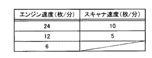
図5は、本発明の実施の形態に従うエンジン速度とスキャナ速度の速度テーブルを説明する図である。当該速度テーブルは、HDD302に格納されているものとする。
FIG. 5 is a diagram illustrating a speed table of engine speed and scanner speed according to the embodiment of the present invention. It is assumed that the speed table is stored in the
ここでは、一例としてA4サイズの用紙の速度が示されている。
スキャナ速度は、2種類が選択可能であり、A4用紙で10(枚/分)、5(枚/分)の速度に変更することが可能である。
Here, as an example, the speed of A4 size paper is shown.
Two types of scanner speeds can be selected and can be changed to 10 (sheets / minute) and 5 (sheets / minute) for A4 paper.
一方、エンジン速度は、3種類を選択可能であり、24(枚/分)、12(枚/分)、6(枚/分)の速度に変更することが可能である。 On the other hand, three types of engine speeds can be selected, and can be changed to speeds of 24 (sheets / minute), 12 (sheets / minute), and 6 (sheets / minute).
図6は、本発明の実施の形態に従うエンジン速度とスキャナ速度との速度差に基づいて各組み合わせを配列した配列テーブルを説明する図である。 FIG. 6 is a diagram illustrating an array table in which the combinations are arranged based on the speed difference between the engine speed and the scanner speed according to the embodiment of the present invention.
図6を参照して、ここでは、3速を持つエンジン速度と、2速のスキャナ速度との速度差に基づいて、合計6個の組み合わせが配列された場合が示されている。 Referring to FIG. 6, here, a case where a total of six combinations are arranged based on the speed difference between the engine speed having the third speed and the scanner speed of the second speed is shown.
具体的には、エンジン速度からスキャナ速度を減算した速度差を算出して、速度差の順番に配列した場合が示されている。また、ここで、スキャナ速度がエンジン速度よりも速い場合を優先させるとともに、速度差が0に近い順に配列する。 Specifically, the case where the speed difference obtained by subtracting the scanner speed from the engine speed is calculated and arranged in the order of the speed difference is shown. Here, priority is given to the case where the scanner speed is higher than the engine speed, and the speed difference is arranged in order of close to zero.
当該速度差に基づく配列は、プリンタが待機する時間が少なくなる順に配列されたものである。 The arrangement based on the speed difference is arranged in the order in which the printer waits for less time.
さらに、速度差とともに、エンジン速度とスキャナ速度との組み合わせに従うファーストコピー時間(FCOT)が計算されたものも示されている。ファーストコピー時間(FCOT)とは、最初の1枚目をスキャンして印字して出力するまでの時間である。当該ファーストコピー時間は、予め定まっているエンジンを起動する時間、スキャナおよびプリンタの速度に応じた読取時間および印字時間等に基づいて算出される。 Also shown is the first copy time (FCOT) calculated according to the combination of engine speed and scanner speed along with the speed difference. The first copy time (FCOT) is a time from scanning the first first sheet to printing and outputting. The first copy time is calculated based on a predetermined engine start time, a reading time and a printing time corresponding to the speeds of the scanner and the printer.
そして、当該配列テーブルに従って最上位の組み合わせであるエンジン速度が6(枚/分)とスキャナ速度が10(枚/分)が選出されて寿命優先として選択された場合が示されている。 In this example, the engine speed of 6 (sheets / minute) and the scanner speed of 10 (sheets / minute), which are the highest combinations, are selected according to the arrangement table and selected as the life priority.
すなわち、本実施の形態においては、基本的に当該配列テーブルに従って、エンジン速度が6(枚/分)とスキャナ速度が10(枚/分)との組み合わせである寿命優先の速度でスキャナにおける原稿読取およびプリンタにおける印字が実行される。 That is, in the present embodiment, basically, according to the arrangement table, the document is read by the scanner at a life priority speed that is a combination of an engine speed of 6 (sheets / minute) and a scanner speed of 10 (sheets / minute). And printing in the printer is executed.
当該速度差に基づく配列に従って、プリンタが待機する時間が少なくなる組み合わせを選択する、すなわち、寿命優先で画像形成を実行することにより簡易な構成で、かつ、画像形成部品の寿命を考慮して適切な速度に設定することが可能となる。 According to the arrangement based on the speed difference, a combination that reduces the waiting time of the printer is selected, that is, an image formation is executed with priority on the lifetime, and the configuration is simple and appropriate considering the lifetime of the image forming component. Speed can be set.
一方で、当該組み合わせは寿命優先であるため高速に画像形成を実行したいというユーザも考えられる。本実施の形態においては、基本的には、寿命優先で選択された組み合わせに従う速度で画像形成を実行するが、ユーザから速度優先の指示入力が有った場合には、性能優先として選択された組み合わせに従う速度で画像形成を実行する。 On the other hand, since the combination has a priority on life, there may be a user who wants to execute image formation at high speed. In the present embodiment, basically, image formation is executed at a speed according to the combination selected with life priority. However, when a speed priority instruction is input from the user, it is selected as performance priority. Image formation is executed at a speed according to the combination.
なお、速度優先の指示入力は図示しないが一例として操作パネル150に所定のボタンとして設けられているものとする。当該所定のボタンが押下されることにより速度優先の指示入力があったと判断されるものとする。なお、本例においては、一例として、所定のボタンが設けられる場合について説明するが、当該ボタンに限られず、例えば、操作ディスプレイ120に選択可能なアイコンとして表示するようにしても良い。あるいは、ユーザの各種モードの設定に従って自動的に速度優先の指示入力があったと判断するようにしても良い。
It should be noted that the speed priority instruction input is provided as a predetermined button on the
本例においては、3番目の組み合わせであるエンジン速度が12(枚/分)とスキャナ速度が10(枚/分)が選出されて性能優先として選択された場合が示されている。すなわち、本実施の形態においては、当該配列テーブルに従って、寿命優先で配列された組み合わせのうち、寿命優先として選択された組み合わせのファーストコピー時間(FCOT)を基準として、当該ファーストコピー時間(FCOT)よりも短い短期間で印字することが可能であれば、その組み合わせを性能優先として選択するものである。 In this example, a case where the third combination of the engine speed of 12 (sheets / minute) and the scanner speed of 10 (sheets / minute) are selected and selected as the performance priority is shown. That is, in the present embodiment, from the first copy time (FCOT) based on the first copy time (FCOT) of the combination selected as the life priority among the combinations arranged with the life priority according to the arrangement table. If it is possible to print in a short short period, the combination is selected as a priority for performance.
当該寿命優先の順番での配列された組み合わせの中から、ファーストコピー時間が短い上位の組み合わせを性能優先の組み合わせとして選択する。当該選択により、ユーザの意向に沿う形で速度を速めるとともに、寿命優先の上位の組み合わせが選択されるため、画像形成部品の寿命を考慮して適切な速度に設定することが可能となる。 From the combinations arranged in the life priority order, the upper combination having a short first copy time is selected as the performance priority combination. By this selection, the speed is increased in accordance with the user's intention, and the combination with higher life priority is selected, so that it is possible to set the speed to an appropriate speed in consideration of the life of the image forming component.
以下、上記寿命優先の組み合わせおよび性能優先の組み合わせを選択する方式について説明する。 Hereinafter, a method for selecting the combination of the life priority and the performance priority will be described.
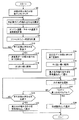
図7は、本発明の実施の形態に従うプリンタのエンジン速度とスキャナ速度との組み合わせを選択するフロー図である。当該選択するフローは、本発明の実施の形態に従うCPU300が実行するものとする。なお、当該選択に従って、CPU300は、選択した組み合わせに従う速度で駆動するようにエンジン制御部145およびスキャナ制御部251にそれぞれ指示するものとする。そして、エンジン制御部145およびスキャナ制御部251は、指示された速度で駆動するものとする。なお、スキャナ制御部251およびエンジン制御部145は、予め図5で示される速度で駆動可能であるものとする。
FIG. 7 is a flowchart for selecting a combination of the engine speed and the scanner speed of the printer according to the embodiment of the present invention. The flow to be selected is executed by
図7を参照して、まず、速度の組み合わせを全てリストアップする(ステップS2)。
次に、エンジン速度とスキャナ速度との速度差の計算をしていない組み合わせを選択する(ステップS4)。
Referring to FIG. 7, first, all speed combinations are listed (step S2).
Next, a combination in which the speed difference between the engine speed and the scanner speed is not calculated is selected (step S4).
次に、エンジン速度からスキャナ速度を減算した速度差を計算する(ステップS6)。
次に、選択した組み合わせに従うファーストコピー時間を計算する(ステップS8)。
Next, a speed difference obtained by subtracting the scanner speed from the engine speed is calculated (step S6).
Next, the first copy time according to the selected combination is calculated (step S8).
次に、全ての組み合わせを計算したかどうかを判断する(ステップS10)。
ステップS10において、全ての組み合わせを計算したと判断した場合(ステップS10においてYES)には、ステップS12に進む。
Next, it is determined whether all combinations have been calculated (step S10).
If it is determined in step S10 that all combinations have been calculated (YES in step S10), the process proceeds to step S12.
一方、ステップS10において、全ての組み合わせを計算していないと判断した場合(ステップS10においてNO)には、ステップS4に戻る。そして、別の組み合わせを選択して、上記で説明したのと同様の方式に従って速度差等の計算を繰り返す。 On the other hand, if it is determined in step S10 that all combinations have not been calculated (NO in step S10), the process returns to step S4. Then, another combination is selected, and the calculation of the speed difference or the like is repeated according to the same method as described above.
そして、全ての組み合わせを計算したと判断した場合に、次に、速度差が「−」の組み合わせ全てを抽出する(ステップS12)。 If it is determined that all combinations have been calculated, then all combinations having a speed difference of “−” are extracted (step S12).
次に、抽出した「−」の組み合わせについて、0に近い順番に配列する(ステップS14)。 Next, the extracted “-” combinations are arranged in the order close to 0 (step S14).
次に、速度差が「+」の組み合わせ全てを抽出する(ステップS16)。
そして、次に、「+」の抽出した組み合わせについて、0に近い順番に配列する(ステップS18)。
Next, all combinations having a speed difference of “+” are extracted (step S16).
Next, the extracted combinations of “+” are arranged in the order close to 0 (step S18).
次に、最上位の組み合わせを寿命優先の組み合わせとして選出する(ステップS20)。上述したように速度差に従って配列されているため最上位の組み合わせを寿命優先と選出する。 Next, the top combination is selected as a life priority combination (step S20). As described above, since the arrangement is made according to the speed difference, the top combination is selected as the life priority.
次に、次の順位を選択する(ステップS22)。
そして、当該選択した順位に対応するファーストコピー時間(FCOT)が最上位のファーストコピー時間よりも短いか否かを判断する(ステップS24)。
Next, the next order is selected (step S22).
Then, it is determined whether or not the first copy time (FCOT) corresponding to the selected order is shorter than the highest first copy time (step S24).
ステップS24において、当該選択した順位に対応するファーストコピー時間(FCOT)が最上位のファーストコピー時間よりも短いと判断した場合(ステップS24においてYES)には、性能優先の組み合わせとして選出する(ステップS26)。 If it is determined in step S24 that the first copy time (FCOT) corresponding to the selected order is shorter than the highest-order first copy time (YES in step S24), it is selected as a performance priority combination (step S26). ).
一方、ステップS24において、当該選択した順位に対応するファーストコピー時間(FCOT)が最上位のファーストコピー時間よりも短くないと判断した場合(ステップS24においてNO)には、ステップS28に進む。 On the other hand, if it is determined in step S24 that the first copy time (FCOT) corresponding to the selected order is not shorter than the highest-order first copy time (NO in step S24), the process proceeds to step S28.
そして、全ての組み合わせを比較したかどうかを判断する(ステップS28)。
ステップS28において、全ての組み合わせを比較していないと判断した場合(ステップS28においてNO)には、ステップS22に戻る。
Then, it is determined whether or not all combinations have been compared (step S28).
If it is determined in step S28 that not all combinations have been compared (NO in step S28), the process returns to step S22.
一方、ステップS28において、全ての組み合わせを比較したと判断した場合(ステップS28においてYES)には、最上位の組み合わせを性能優先として選出する(ステップS30)。 On the other hand, if it is determined in step S28 that all combinations have been compared (YES in step S28), the highest combination is selected as a performance priority (step S30).
そして、処理を終了する(エンド)。
すなわち、寿命優先で配列されている順番に従って、最上位のファーストコピー時間よりも短いファーストコピー時間であるかどうかを1つずつ順番に比較する。そして、当該条件を満たす上位の組み合わせを性能優先として選出するものである。寿命優先で配列されている順番の中からファーストコピー時間の短い組み合わせを選出することが可能であるため寿命を考慮しつつ、速度の速い組み合わせを選択することが可能である。
Then, the process ends (END).
That is, according to the order arranged in the life priority, whether or not the first copy time is shorter than the highest first copy time is sequentially compared. Then, an upper combination satisfying the condition is selected as a performance priority. Since it is possible to select a combination with a short first copy time from the order arranged with priority on the life, it is possible to select a combination with a high speed while considering the life.
なお、全ての組み合わせを比較した場合において、当該条件を満たす組み合わせがない場合には、寿命優先として選出された最上位の組み合わせを性能優先の組み合わせとしても選出する。 When all combinations are compared, if there is no combination that satisfies the condition, the highest combination selected as the life priority is selected as the performance priority combination.
上記の図6の具体例について説明すると、上記ステップS2〜S18の処理に従って、図6で説明した配列に並べられる。 Explaining the specific example of FIG. 6 described above, they are arranged in the array described in FIG.
そして、ステップS20に従って最上位のエンジン速度が6(枚/分)とスキャナ速度が10(枚/分)が寿命優先として選出される。 Then, according to step S20, the highest engine speed of 6 (sheets / minute) and the scanner speed of 10 (sheets / minute) are selected as life priority.
次に、当該最上位のエンジン速度が6(枚/分)とスキャナ速度が10(枚/分)のファーストコピー時間(FCOT)は16(秒)である。ステップS22〜S26の処理に従って、当該ファーストコピー時間よりも短い上位の組み合わせとして、エンジン速度が12(枚/分)とスキャナ速度が10(枚/分)が性能優先として選出される。 Next, the first copy time (FCOT) when the highest engine speed is 6 (sheets / minute) and the scanner speed is 10 (sheets / minute) is 16 (seconds). In accordance with the processing in steps S22 to S26, the engine speed of 12 (sheets / minute) and the scanner speed of 10 (sheets / minute) and the scanner speed of 10 (sheets / minute) are selected as the priority combination as the upper combination shorter than the first copy time.
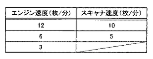
図8は、本発明の実施の形態に従うエンジン速度とスキャナ速度の別の速度テーブルを説明する図である。当該速度テーブルは、HDD302に格納されているものとする。
FIG. 8 is a diagram illustrating another speed table of engine speed and scanner speed according to the embodiment of the present invention. It is assumed that the speed table is stored in the
スキャナ速度は、3種類が選択可能であり、10(枚/分)、5(枚/分)、3(枚/分)の速度に変更することが可能である。 Three types of scanner speeds can be selected, and can be changed to a speed of 10 (sheets / minute), 5 (sheets / minute), and 3 (sheets / minute).
一方、エンジン速度は、2種類を選択可能であり、24(枚/分)、12(枚/分)の速度に変更することが可能である。 On the other hand, two types of engine speeds can be selected and can be changed to a speed of 24 (sheets / minute) or 12 (sheets / minute).
図9は、本発明の実施の形態に従うエンジン速度とスキャナ速度との速度差に基づいて各組み合わせを配列した配列テーブルを説明する図である。 FIG. 9 is a diagram illustrating an array table in which the combinations are arranged based on the speed difference between the engine speed and the scanner speed according to the embodiment of the present invention.
図9を参照して、ここでは、2速を持つエンジン速度と、3速のスキャナ速度との速度差に基づいて、合計6個の組み合わせが配列された場合が示されている。 Referring to FIG. 9, here, a case where a total of six combinations are arranged based on the speed difference between the engine speed having the second speed and the scanner speed of the third speed is shown.
そして、図7で説明したフローに従って配列され、速度差の順番に配列に従って、プリンタが待機する時間が少なくなる組み合わせであるエンジン速度12(枚/分)、スキャナ速度10(枚/分)が選択される。すなわち、寿命優先で画像形成を実行することにより簡易な構成で、かつ、画像形成部品の寿命を考慮して適切な速度に設定することが可能となる。 Then, the engine speed 12 (sheets / minute) and the scanner speed 10 (sheets / minute) are selected, which are arranged according to the flow described in FIG. Is done. That is, by performing image formation with priority on life, it is possible to set to an appropriate speed with a simple configuration and considering the life of the image forming component.
また、上記の図7で説明したフローに従って、当該配列テーブルに従って、寿命優先で配列された組み合わせのうち、寿命優先として選択された組み合わせのファーストコピー時間(FCOT)を基準として、当該ファーストコピー時間(FCOT)よりも短い短期間で印字することが可能なエンジン速度が24(枚/分)とスキャナ速度が10(枚/分)が性能優先として選出される。当該選択により、ユーザの意向に沿う形で速度を速めるとともに、寿命優先の上位の組み合わせが選択されるため、画像形成部品の寿命を考慮して適切な速度に設定することが可能となる。 Further, according to the flow described in FIG. 7, the first copy time (FCOT) of the combination selected as life priority among the combinations arranged with life priority according to the arrangement table is used as a reference. The engine speed of 24 (sheets / minute) and the scanner speed of 10 (sheets / minute) that can be printed in a short period of time shorter than the FCOT are selected as performance priority. By this selection, the speed is increased in accordance with the user's intention, and the combination with higher life priority is selected, so that it is possible to set the speed to an appropriate speed in consideration of the life of the image forming component.
図10は、本発明の本発明の実施の形態に従うエンジン速度とスキャナ速度のさらに別の速度テーブルを説明する図である。当該速度テーブルは、HDD302に格納されているものとする。
FIG. 10 is a diagram illustrating still another speed table of engine speed and scanner speed according to the embodiment of the present invention. It is assumed that the speed table is stored in the
スキャナ速度は、2種類が選択可能であり、10(枚/分)、5(枚/分)の速度に変更することが可能である。 Two types of scanner speeds can be selected and can be changed to a speed of 10 (sheets / minute) and 5 (sheets / minute).
一方、エンジン速度は、3種類を選択可能であり、12(枚/分)、6(枚/分)、3(枚/分)の速度に変更することが可能である。 On the other hand, three types of engine speeds can be selected, and can be changed to speeds of 12 (sheets / minute), 6 (sheets / minute), and 3 (sheets / minute).
当該エンジン速度は、図5で説明したA4サイズの印刷をA3サイズに拡大した場合の速度を示している。 The engine speed indicates the speed when the A4 size printing described in FIG. 5 is enlarged to the A3 size.
図11は、本発明の実施の形態に従うエンジン速度とスキャナ速度との速度差に基づいて各組み合わせを配列した配列テーブルを説明する図である。 FIG. 11 is a diagram illustrating an array table in which the combinations are arranged based on the speed difference between the engine speed and the scanner speed according to the embodiment of the present invention.
図11を参照して、ここでは、3速を持つエンジン速度と、2速のスキャナ速度との速度差に基づいて、合計6個の組み合わせが配列された場合が示されている。 Referring to FIG. 11, here, a case where a total of six combinations are arranged based on the speed difference between the engine speed having the third speed and the scanner speed of the second speed is shown.
そして、図7で説明したフローに従って配列され、速度差の順番に配列に従って、プリンタが待機する時間が少なくなる組み合わせであるエンジン速度が3(枚/分)、スキャナ速度が5(枚/分)が選択される。すなわち、寿命優先で画像形成を実行することにより簡易な構成で、かつ、画像形成部品の寿命を考慮して適切な速度に設定することが可能となる。 Then, the engine speed is 3 (sheets / minute) and the scanner speed is 5 (sheets / minute), which is a combination that is arranged in accordance with the flow described in FIG. Is selected. That is, by performing image formation with priority on life, it is possible to set to an appropriate speed with a simple configuration and considering the life of the image forming component.
また、上記の図7で説明したフローに従って、当該配列テーブルに従って、寿命優先で配列された組み合わせのうち、寿命優先として選択された組み合わせのファーストコピー時間(FCOT)を基準として、当該ファーストコピー時間(FCOT)よりも短い短期間で印字することが可能なエンジン速度が6(枚/分)とスキャナ速度が10(枚/分)が性能優先として選出される。当該選択により、ユーザの意向に沿う形で速度を速めるとともに、寿命優先の上位の組み合わせが選択されるため、画像形成部品の寿命を考慮して適切な速度に設定することが可能となる。 Further, according to the flow described in FIG. 7, the first copy time (FCOT) of the combination selected as life priority among the combinations arranged with life priority according to the arrangement table is used as a reference. The engine speed of 6 (sheets / minute) and the scanner speed of 10 (sheets / minute) and the scanner speed of 10 (sheets / minute) that can be printed in a short period of time shorter than the FCOT) are selected as priority. By this selection, the speed is increased in accordance with the user's intention, and the combination with higher life priority is selected, so that it is possible to set the speed to an appropriate speed in consideration of the life of the image forming component.
なお、本例においては、印刷用紙のサイズの拡大に従って速度が変更される場合について説明したが、印刷用紙のサイズの拡大に限られず、縮小の場合についても同様に速度が変更される。 In this example, the case where the speed is changed according to the enlargement of the size of the printing paper has been described. However, the speed is not limited to the enlargement of the size of the printing paper, and the speed is similarly changed in the case of the reduction.
また、コピーモード(カラー/モノクロ)の相違やスキャナの解像度の指定によっても速度が変更される。そして、変更された速度の組み合わせに従って上記した方式に従って最適な組み合わせを選択するものとする。なお、印刷用紙のサイズの変更、スキャナの解像度の指定、コピーモード(カラー/モノクロ)等の選択は、操作パネル150を介してユーザによって指定されるものである。当該操作パネルを介したユーザからの各種モードの設定入力に従って、予めHDD302に格納されている各種モードに対応する速度テーブルが参照されて、最適な組み合わせを選択することが可能である。
The speed is also changed depending on the copy mode (color / monochrome) difference and the scanner resolution designation. Then, the optimum combination is selected according to the above-described method according to the changed speed combination. The change of the size of the printing paper, the specification of the scanner resolution, the selection of the copy mode (color / monochrome), and the like are specified by the user via the
なお、本例においては、スキャナ速度とエンジン速度とが組としたテーブルが示されているが、特に当該組とするテーブルに限られず、スキャナ速度のテーブル、エンジン速度のテーブルがそれぞれ独立に格納されていても良い。 In this example, a table in which the scanner speed and the engine speed are set is shown. However, the table is not limited to the table in particular, and the scanner speed table and the engine speed table are stored separately. May be.
なお、本発明にかかる画像形成装置は、MFPに限定されない。また、スキャナ130とプリンタ140とが一体として成型された画像形成装置に限られず、別体としてそれぞれ独立に成型されたスキャナ130とプリンタ140とを組み合わせた構成とすることも可能である。なお、組み合わせる際には、互いにアクセス可能なように通信経路が設けられ、一例としてCPU300からそれぞれを制御可能に接続されるものとする。また、HDD302にスキャナ130およびプリンタ140の上述した速度テーブルを格納するものとする。
The image forming apparatus according to the present invention is not limited to the MFP. In addition, the image forming apparatus is not limited to the image forming apparatus in which the
なお、コンピュータ(CPU)を機能させて、上述のフローで説明したような制御を実行させるプログラムを提供することもできる。このようなプログラムは、コンピュータに付属するフレキシブルディスク、CD−ROM(Compact Disk-Read Only Memory)、ROM(Read Only Memory)、RAM(Random Access Memory)およびメモリカードなどの一時的でないコンピュータ読取り可能な記録媒体にて記録させて、プログラム製品として提供することもできる。あるいは、コンピュータに内蔵するハードディスクなどの記録媒体にて記録させて、プログラムを提供することもできる。また、ネットワークを介したダウンロードによって、プログラムを提供することもできる。 It is also possible to provide a program that causes a computer (CPU) to function and execute control as described in the above flow. Such a program can be read by a non-transitory computer such as a flexible disk attached to a computer, a CD-ROM (Compact Disk-Read Only Memory), a ROM (Read Only Memory), a RAM (Random Access Memory), and a memory card. It can also be recorded on a recording medium and provided as a program product. Alternatively, the program can be provided by being recorded on a recording medium such as a hard disk built in the computer. A program can also be provided by downloading via a network.
なお、プログラムは、コンピュータのオペレーションシステム(OS)の一部として提供されるプログラムモジュールのうち、必要なモジュールを所定の配列で所定のタイミングで呼出して処理を実行させるものであってもよい。その場合、プログラム自体には上記モジュールが含まれずOSと協働して処理が実行される。このようなモジュールを含まないプログラムも、本発明にかかるプログラムに含まれ得る。 The program may be a program module that is provided as a part of a computer operation system (OS) and that calls necessary modules in a predetermined arrangement at a predetermined timing to execute processing. In that case, the program itself does not include the module, and the process is executed in cooperation with the OS. A program that does not include such a module can also be included in the program according to the present invention.
また、本発明にかかるプログラムは他のプログラムの一部に組込まれて提供されるものであってもよい。その場合にも、プログラム自体には上記他のプログラムに含まれるモジュールが含まれず、他のプログラムと協働して処理が実行される。このような他のプログラムに組込まれたプログラムも、本発明にかかるプログラムに含まれ得る。 The program according to the present invention may be provided by being incorporated in a part of another program. Even in this case, the program itself does not include the module included in the other program, and the process is executed in cooperation with the other program. Such a program incorporated in another program can also be included in the program according to the present invention.
提供されるプログラム製品は、ハードディスクなどのプログラム格納部にインストールされて実行される。なお、プログラム製品は、プログラム自体と、プログラムが記録された記録媒体とを含む。 The provided program product is installed in a program storage unit such as a hard disk and executed. The program product includes the program itself and a recording medium on which the program is recorded.
今回開示された実施の形態はすべての点で例示であって制限的なものではないと考えられるべきである。本発明の範囲は上記した説明ではなくて特許請求の範囲によって示され、特許請求の範囲と均等の意味および範囲内でのすべての変更が含まれることが意図される。 The embodiment disclosed this time should be considered as illustrative in all points and not restrictive. The scope of the present invention is defined by the terms of the claims, rather than the description above, and is intended to include any modifications within the scope and meaning equivalent to the terms of the claims.
2 中間転写ベルト、3 感光体、4 現像装置、5 帯電装置、6 露光装置、7 中間転写ベルトクリーナ、8 カセット給紙ローラ、9 手差し給紙ローラ、22 用紙材質検知センサ、24a,24b,24c,24d トナー補給モータ、25 トナーボトル、26,26a 攪拌羽、27 定着ループセンサ、28 カートリッジ、29 用紙検知センサ、31 二次転写ローラ、32a 定着ローラ、32b 加圧ローラ、33,230 排紙ローラ、34a 両面搬送ローラ、35 両面搬送経路、36 廃トナーボックス、38 タイミングローラ、40 カラー用現像モータ、42 現像モータ、44 メインモータ、45 両面搬送モータ、46 定着モータ、100 画像形成装置、110 操作部、120 操作ディスプレイ、130 スキャナ、140 プリンタ、145 エンジン制御部、150 操作パネル、162 ピックアップローラ、163 原稿検出センサ、180 給紙部、190 トレイ、211 給紙トレイ、213 給紙ローラ、215 分離ローラ、217 レジストローラ、243 第1画像処理部、245 第2画像処理部、251 スキャナ制御部、261 ADF制御部、306 ROM、308 RAM、312 ネットワークカード、314 モデム。 2 Intermediate transfer belt, 3 photosensitive member, 4 developing device, 5 charging device, 6 exposure device, 7 intermediate transfer belt cleaner, 8 cassette paper feed roller, 9 manual paper feed roller, 22 paper material detection sensors, 24a, 24b, 24c , 24d toner supply motor, 25 toner bottle, 26, 26a stirring blade, 27 fixing loop sensor, 28 cartridge, 29 paper detection sensor, 31 secondary transfer roller, 32a fixing roller, 32b pressure roller, 33, 230 paper discharge roller 34a Double-sided conveyance roller, 35 Double-sided conveyance path, 36 Waste toner box, 38 Timing roller, 40 Color development motor, 42 Development motor, 44 Main motor, 45 Double-sided conveyance motor, 46 Fixing motor, 100 Image forming apparatus, 110 Operation Part, 120 operation display, 130 Scanner, 140 Printer, 145 Engine control unit, 150 Operation panel, 162 Pickup roller, 163 Document detection sensor, 180 Paper feed unit, 190 tray, 211 Paper feed tray, 213 Paper feed roller, 215 Separation roller, 217 Registration roller, 243 First image processing unit, 245 Second image processing unit, 251 Scanner control unit, 261 ADF control unit, 306 ROM, 308 RAM, 312 network card, 314 modem.
Claims (7)
前記スキャナで読み取った画像データを複数の印字速度で印字することが可能な画像形成部と、
前記スキャナおよび前記画像形成部の駆動を制御するためのコントローラとを備え、
前記コントローラは、前記スキャナの前記複数の読取速度および前記画像形成部の前記複数の印字速度に基づいて、前記複数の読取速度と前記複数の印字速度との複数の組み合わせのうち前記画像形成部が待機する時間が少なくなる読取速度と印字速度との組み合わせを選択してそれぞれを駆動する、画像形成装置。 A scanner capable of reading a document at a plurality of reading speeds;
An image forming unit capable of printing image data read by the scanner at a plurality of printing speeds;
A controller for controlling the driving of the scanner and the image forming unit,
The controller is configured such that, based on the plurality of reading speeds of the scanner and the plurality of printing speeds of the image forming unit, the image forming unit out of a plurality of combinations of the plurality of reading speeds and the plurality of printing speeds. An image forming apparatus that selects a combination of a reading speed and a printing speed that reduces waiting time and drives each of them.
前記スキャナの前記複数の読取速度および前記画像形成部の前記複数の印字速度に基づいて、前記複数の読取速度と前記複数の印字速度との複数の組み合わせのうち、前記画像形成部の各前記印字速度から前記スキャナの各前記読取速度をそれぞれ減算した速度差を算出し、
前記読取速度の方が前記印字速度よりも速い場合を前記読取速度の方が前記印字速度よりも遅い場合よりも優先して、算出された速度差および速度差が0に近い順番に従って配列し、
前記配列された前記複数の組み合わせのうち最上位の読取速度と印字速度との組み合わせを選択してそれぞれ駆動する、請求項1記載の画像形成装置。 The controller is
Based on the plurality of reading speeds of the scanner and the plurality of printing speeds of the image forming unit, each print of the image forming unit among a plurality of combinations of the plurality of reading speeds and the plurality of printing speeds. Calculate a speed difference obtained by subtracting each reading speed of the scanner from the speed,
When the reading speed is faster than the printing speed, the reading speed is prioritized over the case where the printing speed is slower than the printing speed, and the calculated speed difference and the speed difference are arranged according to the order close to 0,
The image forming apparatus according to claim 1, wherein a combination of the highest reading speed and printing speed is selected and driven from among the plurality of combinations arranged in the array.
前記コントローラは、前記受付手段による前記速度を有線する指定を受け付けた場合には、前記配列された前記複数の組み合わせのうち最上位の読取速度と印字速度との組み合わせにおける1枚目の印刷時間と、複数の下位の読取速度と印字速度との組み合わせにおける1枚目の印刷時間とを比較して、前記最上位の読取速度と印字速度との組み合わせにおける1枚目の印刷時間よりも早い印刷時間の下位の読取速度と印字速度との組み合わせを選択してそれぞれ駆動する、請求項3記載の画像形成装置。 It further comprises a receiving means for receiving a specification giving priority to speed,
The controller, when receiving the designation to wire the speed by the receiving means, the printing time of the first sheet in the combination of the highest reading speed and the printing speed among the plurality of the arranged combinations The printing time that is faster than the printing time of the first sheet in the combination of the highest reading speed and the printing speed is compared with the printing time of the first sheet in the combination of the plurality of lower reading speeds and the printing speed. The image forming apparatus according to claim 3, wherein a combination of a lower reading speed and a printing speed is selected and driven.
前記入力手段によるモードの指定の入力に従って、前記スキャナによる前記複数の読取速度および前記画像形成部における前記複数の印字速度の少なくとも一方は変更される、請求項1〜5のいずれかに記載の画像形成装置。 It further comprises an input means capable of accepting a plurality of mode designation inputs,
6. The image according to claim 1, wherein at least one of the plurality of reading speeds by the scanner and the plurality of printing speeds in the image forming unit is changed according to a mode designation input by the input unit. Forming equipment.
Priority Applications (1)
| Application Number | Priority Date | Filing Date | Title |
|---|---|---|---|
| JP2010248916A JP2012104875A (en) | 2010-11-05 | 2010-11-05 | Image forming apparatus |
Applications Claiming Priority (1)
| Application Number | Priority Date | Filing Date | Title |
|---|---|---|---|
| JP2010248916A JP2012104875A (en) | 2010-11-05 | 2010-11-05 | Image forming apparatus |
Publications (1)
| Publication Number | Publication Date |
|---|---|
| JP2012104875A true JP2012104875A (en) | 2012-05-31 |
Family
ID=46394833
Family Applications (1)
| Application Number | Title | Priority Date | Filing Date |
|---|---|---|---|
| JP2010248916A Withdrawn JP2012104875A (en) | 2010-11-05 | 2010-11-05 | Image forming apparatus |
Country Status (1)
| Country | Link |
|---|---|
| JP (1) | JP2012104875A (en) |
-
2010
- 2010-11-05 JP JP2010248916A patent/JP2012104875A/en not_active Withdrawn
Similar Documents
| Publication | Publication Date | Title |
|---|---|---|
| JP4289851B2 (en) | Image forming apparatus | |
| US7443406B2 (en) | Tandem image forming apparatus | |
| JP2012100290A (en) | Image forming apparatus | |
| US20080175622A1 (en) | Image forming apparatus and image forming method | |
| JP4782735B2 (en) | Image processing device | |
| JP2009010602A (en) | Image forming apparatus | |
| JP2000310922A (en) | Image forming device | |
| JP3750301B2 (en) | Image forming apparatus | |
| JP2007235852A (en) | Image reading apparatus | |
| JP5447877B2 (en) | Image forming apparatus | |
| JP2011164602A (en) | Image forming apparatus and image processing method | |
| JP2012104875A (en) | Image forming apparatus | |
| JP2008257248A (en) | Image forming apparatus | |
| JP3721769B2 (en) | Image forming apparatus | |
| JP4310129B2 (en) | Document feeding apparatus, image forming apparatus, method for controlling document feeding apparatus, and method for controlling image forming apparatus | |
| JP2013059969A (en) | Data processing apparatus and data file | |
| JP2007036732A (en) | Image reading apparatus and image forming apparatus | |
| JP2006191229A (en) | Image scanner and image forming apparatus | |
| JP4037776B2 (en) | Image forming apparatus | |
| JP2006194963A (en) | Image forming apparatus | |
| JP2010176001A (en) | Image forming apparatus, fixing temperature control method, and fixing temperature control program | |
| JPH11109706A (en) | Image forming device | |
| JP2005348171A (en) | Image reading device and image forming device | |
| JP3592067B2 (en) | Image forming device | |
| JP2012103275A (en) | Image forming device |
Legal Events
| Date | Code | Title | Description |
|---|---|---|---|
| A711 | Notification of change in applicant |
Free format text: JAPANESE INTERMEDIATE CODE: A712 Effective date: 20130416 |
|
| A300 | Withdrawal of application because of no request for examination |
Free format text: JAPANESE INTERMEDIATE CODE: A300 Effective date: 20140107 |