JP2012103615A - Illumination device and projector - Google Patents

Illumination device and projector Download PDF

Info

Publication number
JP2012103615A
JP2012103615A JP2010254026A JP2010254026A JP2012103615A JP 2012103615 A JP2012103615 A JP 2012103615A JP 2010254026 A JP2010254026 A JP 2010254026A JP 2010254026 A JP2010254026 A JP 2010254026A JP 2012103615 A JP2012103615 A JP 2012103615A
Authority
JP
Japan
Prior art keywords
light
fluorescent layer
source device
light source
lens
Prior art date
Legal status (The legal status is an assumption and is not a legal conclusion. Google has not performed a legal analysis and makes no representation as to the accuracy of the status listed.)
Pending
Application number
JP2010254026A
Other languages
Japanese (ja)
Inventor
Shigeo Nojima
重男 野島
Akira Miyamae
章 宮前
Hidefumi Sakata
秀文 坂田
Satoshi Hashimoto
聡 橋本
Current Assignee (The listed assignees may be inaccurate. Google has not performed a legal analysis and makes no representation or warranty as to the accuracy of the list.)
Seiko Epson Corp
Original Assignee
Seiko Epson Corp
Priority date (The priority date is an assumption and is not a legal conclusion. Google has not performed a legal analysis and makes no representation as to the accuracy of the date listed.)
Filing date
Publication date
Application filed by Seiko Epson Corp filed Critical Seiko Epson Corp
Priority to JP2010254026A priority Critical patent/JP2012103615A/en
Publication of JP2012103615A publication Critical patent/JP2012103615A/en
Pending legal-status Critical Current

Links

Images

Abstract

PROBLEM TO BE SOLVED: To provide an illumination device capable of preventing lowering of luminous efficiency of a fluorescent layer even when output of an excitation light source device is enhanced.SOLUTION: An illumination device 101 of the invention includes a first light source device 10a for emitting a first light beam La, a second light source device 10b for emitting a second light beam Lb, a fluorescent layer 42 excited by the first light beam La and the second light beam Lb, a light diffusion member 26a disposed on an optical path of the first light beam La between the first light source device 10a and the fluorescent layer 42 to diffuse the light beam La, and a light collection optical system 21 for projecting the first light beam La and the second light beam Lb onto the fluorescent layer 42 so that at least a part of the first light beam La and at least a part of the second light beam Lb are overlapped with each other on the fluorescent layer 42.

Description

本発明は、照明装置、プロジェクターに関するものである。   The present invention relates to a lighting device and a projector.

プロジェクター用の照明装置として、特許文献1に記載の照明装置が知られている。特許文献1の照明装置は、励起光(青色光)を射出する光源と、モーターにより回転される円板上に2種類の蛍光層(赤色蛍光層と緑色蛍光層)を形成してなる蛍光板と、を備えている。円板上には、回転方向に沿って3つのセグメント領域が形成されている。3つのセグメント領域のうち2つのセグメント領域には、互いに異なる色光(赤色光と緑色光)を放射する2種類の蛍光層が形成され、残りのセグメント領域には、励起光(青色光)を散乱する散乱体が形成されている。特許文献1の照明装置によれば、励起光と2種類の蛍光層とを用いて3つの色光を順次放射可能な照明装置を提供することができる。   As a lighting device for a projector, a lighting device described in Patent Document 1 is known. The illumination device of Patent Document 1 includes a light source that emits excitation light (blue light), and a fluorescent plate that is formed by forming two types of fluorescent layers (a red fluorescent layer and a green fluorescent layer) on a disc that is rotated by a motor. It is equipped with. On the disk, three segment regions are formed along the rotation direction. Two of the three segment areas are formed with two types of fluorescent layers that emit different colored light (red light and green light), and the remaining segment areas scatter excitation light (blue light). A scatterer is formed. According to the illuminating device of patent document 1, the illuminating device which can radiate | emit three color lights sequentially using excitation light and two types of fluorescent layers can be provided.

特開2009−277516号公報JP 2009-277516 A

特許文献1の照明装置では、励起用の光源装置として、レーザー光源が用いられている。特許文献1の照明装置において放射光の光強度を高める場合には、蛍光層の小面積な部位に高出力のレーザー光(励起光)を集中して照射する必要がある。しかし、蛍光層の小面積な部位に照射するレーザー光の出力を高くすればするほど、蛍光層の発光効率が低下するという課題が発生する。その原因としては、励起光が照射された部位の温度が急激に上昇するということや、励起光の光密度が高くなると、励起光吸収による吸収準位の数密度の減少が無視できなくなり、励起光の吸収率が低下するということなどが考えられる。前者は温度消光現象と呼ばれ、後者は飽和励起現象と呼ばれる。   In the illumination device of Patent Document 1, a laser light source is used as a light source device for excitation. When increasing the light intensity of radiated light in the illumination device of Patent Document 1, it is necessary to concentrate and irradiate high-power laser light (excitation light) on a small area of the fluorescent layer. However, the higher the output of the laser light that irradiates a small area of the fluorescent layer, the lower the luminous efficiency of the fluorescent layer. This is because the temperature of the part irradiated with the excitation light suddenly rises, and when the light density of the excitation light increases, the decrease in the number density of the absorption levels due to absorption of the excitation light cannot be ignored. It can be considered that the light absorption rate decreases. The former is called a temperature quenching phenomenon, and the latter is called a saturation excitation phenomenon.

本発明はこのような事情に鑑みてなされたものであって、励起用光源装置の出力を高めた場合であっても蛍光層の発光効率の低下を抑制可能な照明装置及びプロジェクターを提供することを目的とする。   The present invention has been made in view of such circumstances, and provides an illumination device and a projector capable of suppressing a decrease in the luminous efficiency of the fluorescent layer even when the output of the excitation light source device is increased. With the goal.

上記の課題を解決するため、本発明の照明装置は、第1の光を射出する第1の光源装置と、第2の光を射出する第2の光源装置と、前記第1の光及び前記第2の光によって励起される蛍光層と、前記第1の光源装置と前記蛍光層との間の前記第1の光の光路上に配置され、前記第1の光を拡散させる光拡散部材と、前記第1の光の少なくとも一部と前記第2の光の少なくとも一部とが前記蛍光層上において互いに重なりあうように、前記第1の光と前記第2の光とを前記蛍光層に照射する集光光学系と、を備えていることを特徴とする。   In order to solve the above-described problems, an illumination device according to the present invention includes a first light source device that emits first light, a second light source device that emits second light, the first light, and the light source device. A fluorescent layer excited by second light, a light diffusing member disposed on the optical path of the first light between the first light source device and the fluorescent layer, and diffusing the first light; The first light and the second light are applied to the fluorescent layer such that at least a part of the first light and at least a part of the second light overlap each other on the fluorescent layer. And a condensing optical system for irradiation.

この構成によれば、励起光として蛍光層に照射される光の蛍光層上での光強度分布において、突出して大きい光強度を有する部位が発生することが抑制される。そのため、励起用光源装置の出力を高くした時に起こる発光効率の低下が抑制され、明るい照明装置が提供される。   According to this configuration, in the light intensity distribution on the fluorescent layer of the light irradiated to the fluorescent layer as excitation light, the occurrence of a portion having a large light intensity is suppressed. Therefore, a decrease in luminous efficiency that occurs when the output of the excitation light source device is increased is suppressed, and a bright illumination device is provided.

前記集光光学系は、前記光拡散部材によって拡散された前記第1の光が入射するコリメートレンズと、前記コリメートレンズから射出された前記第1の光が入射する集光レンズと、を備えていることが望ましい。   The condensing optical system includes a collimating lens on which the first light diffused by the light diffusing member is incident, and a condensing lens on which the first light emitted from the collimating lens is incident. It is desirable.

この構成によれば、光拡散部材によって拡散された励起光を集光レンズに効率よく入射させることができる。   According to this configuration, the excitation light diffused by the light diffusing member can be efficiently incident on the condenser lens.

前記光拡散部材は、ホログラム素子であることが望ましい。   The light diffusing member is preferably a hologram element.

この構成によれば、樹脂からなる基材に散乱微粒子を含有させた光拡散部材に比べて、均一性の高い光強度分布を形成することができる。   According to this structure, compared with the light-diffusion member which made the base material which consists of resin contain the scattering fine particle, a highly uniform light intensity distribution can be formed.

前記光拡散部材によって拡散された前記第1の光の光強度分布は、前記第1の光の中心軸にまたがって平坦部を有する光強度分布であることが望ましい。   The light intensity distribution of the first light diffused by the light diffusing member is preferably a light intensity distribution having a flat portion across the central axis of the first light.

この構成によれば、均一性の高い光強度分布を形成することができる。   According to this configuration, a highly uniform light intensity distribution can be formed.

前記光拡散部材は、前記蛍光層が一面側に形成された板材であることが望ましい。   The light diffusing member is preferably a plate having the fluorescent layer formed on one side.

この構成によれば、蛍光層の近傍で励起光が拡散されるため、小さな領域で蛍光層を発光させることができる。そのため、蛍光層の発光効率を高めることができ、明るい照明装置が提供される。   According to this configuration, since the excitation light is diffused in the vicinity of the fluorescent layer, the fluorescent layer can emit light in a small region. Therefore, the luminous efficiency of the fluorescent layer can be increased, and a bright illumination device is provided.

前記蛍光層は、モーターにより回転される板材上に、前記板材の回転方向に沿って連続して形成されていることが望ましい。   The fluorescent layer is preferably formed continuously on a plate material rotated by a motor along the rotation direction of the plate material.

この構成によれば、励起光の照射により生じた蛍光層の熱を板材の回転方向に沿った広い領域において放散させることができる。そのため、励起用光源装置の出力を高くした時に起こる発光効率の低下が抑制され、明るい照明装置が提供される。   According to this configuration, the heat of the fluorescent layer generated by the excitation light irradiation can be dissipated in a wide region along the rotation direction of the plate material. Therefore, a decrease in luminous efficiency that occurs when the output of the excitation light source device is increased is suppressed, and a bright illumination device is provided.

前記第1の光源装置は、前記第1の光としてレーザー光を射出するレーザー光源であり、前記第2の光源装置は、前記第2の光としてレーザー光を射出するレーザー光源であることが望ましい。   It is desirable that the first light source device is a laser light source that emits laser light as the first light, and the second light source device is a laser light source that emits laser light as the second light. .

この構成によれば、集光性の高いレーザー光源を光源装置として用いるため、小さな領域で蛍光層を発光させることができる。そのため、蛍光層の発光効率を高めることができ、明るい照明装置が提供される。   According to this configuration, since the highly condensing laser light source is used as the light source device, the fluorescent layer can emit light in a small area. Therefore, the luminous efficiency of the fluorescent layer can be increased, and a bright illumination device is provided.

本発明のプロジェクターは、本発明の照明装置と、前記照明装置からの照明光を画像情報に応じて変調する光変調装置と、前記光変調装置からの変調光を投写画像として投写する投写光学系と、を備えていることを特徴とする。   The projector according to the present invention includes the illumination device according to the present invention, a light modulation device that modulates illumination light from the illumination device according to image information, and a projection optical system that projects the modulated light from the light modulation device as a projection image. And.

この構成によれば、明るい投写画像を表示することが可能なプロジェクターが提供される。   According to this configuration, a projector capable of displaying a bright projection image is provided.

第1実施形態のプロジェクターの光学系を示す上面図である。FIG. 2 is a top view showing an optical system of the projector according to the first embodiment. 第1実施形態の光源装置及び蛍光層の発光特性を示すグラフである。It is a graph which shows the light emission characteristic of the light source device of 1st Embodiment, and a fluorescent layer. 第1実施形態の回転蛍光板の説明図である。It is explanatory drawing of the rotation fluorescent screen of 1st Embodiment. レーザー光の光強度分布を示す図である。It is a figure which shows light intensity distribution of a laser beam. 第2実施形態のプロジェクターの光学系を示す上面図である。It is a top view which shows the optical system of the projector of 2nd Embodiment. 第3実施形態のプロジェクターの光学系を示す上面図である。It is a top view which shows the optical system of the projector of 3rd Embodiment. 第4実施形態のプロジェクターの光学系を示す上面図である。It is a top view which shows the optical system of the projector of 4th Embodiment. 第2光源装置の発光特性を示すグラフである。It is a graph which shows the light emission characteristic of a 2nd light source device.

[第1実施形態]
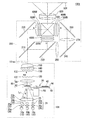
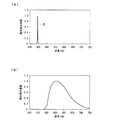
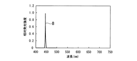
図1は第1実施形態のプロジェクター1001の光学系を示す上面図である。図2は、プロジェクター1001に備えられる光源装置10及び蛍光層42の発光特性を示すグラフである。図2(a)は光源装置10の発光特性を示すグラフであり、図2(b)は蛍光層42の発光特性を示すグラフである。光源装置10の発光特性とは、電圧を印加したときに、どのような波長の光をどのくらいの強度で射出するのかという特性のことをいう。また、蛍光層42の発光特性とは、励起光が入射したときに、どのような波長の光をどのくらいの強度で射出するのかという特性のことをいう。グラフの縦軸は相対発光強度を表し、発光強度が最も大きい波長における発光強度を1としている。グラフの横軸は波長を表す。図3はプロジェクター1001に備えられる回転蛍光板30の説明図である。図3(a)は回転蛍光板30の正面図であり、図3(b)は図3(a)のA1−A1断面図である。
[First Embodiment]
FIG. 1 is a top view showing an optical system of the projector 1001 according to the first embodiment. FIG. 2 is a graph showing the light emission characteristics of the light source device 10 and the fluorescent layer 42 provided in the projector 1001. FIG. 2A is a graph showing the light emission characteristics of the light source device 10, and FIG. 2B is a graph showing the light emission characteristics of the fluorescent layer 42. The light emission characteristic of the light source device 10 refers to a characteristic of how much light is emitted with what intensity when a voltage is applied. Further, the light emission characteristic of the fluorescent layer 42 refers to a characteristic of how much light is emitted with what intensity when excitation light is incident. The vertical axis of the graph represents the relative light emission intensity, and the light emission intensity at the wavelength with the highest light emission intensity is 1. The horizontal axis of the graph represents the wavelength. FIG. 3 is an explanatory diagram of the rotating fluorescent plate 30 provided in the projector 1001. 3A is a front view of the rotating fluorescent plate 30, and FIG. 3B is a cross-sectional view taken along line A1-A1 of FIG.

図1に示すように、プロジェクター1001は、照明装置101、色分離導光光学系200、光変調装置としての液晶光変調装置400R,液晶光変調装置400G,液晶光変調装置400B、クロスダイクロイックプリズム500及び投写光学系600を備えている。   As shown in FIG. 1, the projector 1001 includes an illumination device 101, a color separation light guide optical system 200, a liquid crystal light modulation device 400R as a light modulation device, a liquid crystal light modulation device 400G, a liquid crystal light modulation device 400B, and a cross dichroic prism 500. And a projection optical system 600.

照明装置101は、光源装置10a、光源装置10b、光源装置10c、集光光学系21、回転蛍光板30、モーター50、コリメート光学系60、第1レンズアレイ120、第2レンズアレイ130、偏光変換素子140及び重畳レンズ150を備えている。   The illumination device 101 includes a light source device 10a, a light source device 10b, a light source device 10c, a condensing optical system 21, a rotating fluorescent plate 30, a motor 50, a collimating optical system 60, a first lens array 120, a second lens array 130, and a polarization conversion element. 140 and a superimposing lens 150 are provided.

光源装置10a、光源装置10b、光源装置10cの各々は、青色のレーザー光(発光強度のピーク:約445nm、図2(a)参照)を射出するレーザー光源である。本明細書では、光源装置10aと光源装置10bと光源装置10cとをまとめて光源装置10と呼ぶことがあり、光源装置10aから射出されるレーザー光Laと光源装置10bから射出されるレーザー光Lbと光源装置10cから射出されるレーザー光Lcとをまとめてレーザー光Lと呼ぶことがある。光源装置10aは第1の光源装置に相当し、光源装置10bは第2の光源装置に相当し、レーザー光Laは第1の光に相当し、レーザー光Lbは第2の光に相当する。   Each of the light source device 10a, the light source device 10b, and the light source device 10c is a laser light source that emits blue laser light (emission intensity peak: about 445 nm, see FIG. 2A). In this specification, the light source device 10a, the light source device 10b, and the light source device 10c may be collectively referred to as the light source device 10, and the laser light La emitted from the light source device 10a and the laser light Lb emitted from the light source device 10b. And the laser beam Lc emitted from the light source device 10c may be collectively referred to as a laser beam L. The light source device 10a corresponds to the first light source device, the light source device 10b corresponds to the second light source device, the laser light La corresponds to the first light, and the laser light Lb corresponds to the second light.

図2(a)において、符号Bは、光源装置10が射出するレーザー光Lの色光成分である。図1に示した照明装置101は3つの光源装置10(光源装置10a、光源装置10b、光源装置10c)を備えているが、光源装置10の数はこれに限らず、2つ若しくは4つ以上でもよい。また、445nm以外の波長(例えば460nm)の青色光を励起光として射出する光源装置を用いることもできる。光源装置10aから射出されるレーザー光Laと光源装置10bから射出されるレーザー光Lbと光源装置10cから射出されるレーザー光Lcとが、集光光学系21によって蛍光層42上において互いに重ね合わされることによって、蛍光層42を励起する励起光が形成される。   In FIG. 2A, the symbol B is a color light component of the laser light L emitted from the light source device 10. The illumination device 101 illustrated in FIG. 1 includes three light source devices 10 (light source device 10a, light source device 10b, and light source device 10c), but the number of light source devices 10 is not limited to this, and two or four or more. But you can. A light source device that emits blue light having a wavelength other than 445 nm (for example, 460 nm) as excitation light can also be used. The laser light La emitted from the light source device 10a, the laser light Lb emitted from the light source device 10b, and the laser light Lc emitted from the light source device 10c are superimposed on each other on the fluorescent layer 42 by the condensing optical system 21. Thus, excitation light for exciting the fluorescent layer 42 is formed.

集光光学系21は、光拡散部材26aと、光拡散部材26bと、光拡散部材26cと、第1レンズ23aと、第1レンズ23bと、第1レンズ23cと、第2レンズ25とを備えている。光拡散部材26aおよび第1レンズ23aは光源装置10aに対応して設けられ、光拡散部材26bおよび第1レンズ23bは光源装置10bに対応して設けられ、光拡散部材26cおよび第1レンズ23cは光源装置10cに対応して設けられている。集光光学系21は、光源装置10から回転蛍光板30までの光路中に配置され、レーザー光Laとレーザー光Lbとレーザー光Lcとを略集光した状態で蛍光層42に入射させる。本明細書では、光拡散部材26aと光拡散部材26bと光拡散部材26cとをまとめて光拡散部材26と呼び、第1レンズ23aと第1レンズ23bと第1レンズ23cとをまとめて第1レンズ23と呼ぶことがある。   The condensing optical system 21 includes a light diffusing member 26a, a light diffusing member 26b, a light diffusing member 26c, a first lens 23a, a first lens 23b, a first lens 23c, and a second lens 25. ing. The light diffusion member 26a and the first lens 23a are provided corresponding to the light source device 10a, the light diffusion member 26b and the first lens 23b are provided corresponding to the light source device 10b, and the light diffusion member 26c and the first lens 23c are provided. It is provided corresponding to the light source device 10c. The condensing optical system 21 is disposed in the optical path from the light source device 10 to the rotating fluorescent plate 30 and causes the laser light La, the laser light Lb, and the laser light Lc to enter the fluorescent layer 42 in a substantially condensed state. In this specification, the light diffusing member 26a, the light diffusing member 26b, and the light diffusing member 26c are collectively referred to as the light diffusing member 26, and the first lens 23a, the first lens 23b, and the first lens 23c are collectively referred to as the first. Sometimes referred to as a lens 23.

光拡散部材26は、例えば、光源装置10から射出されたレーザー光Lを散乱する散乱粒子を備えた透明な樹脂の板材からなる。光拡散部材26は、光源装置10から射出されたレーザー光Lを拡散させる。具体時には、光拡散部材26aはレーザー光Laを拡散させ、光拡散部材26bはレーザー光Lbを拡散させ、光拡散部材26cはレーザー光Lcを拡散させる。図1では、1つの光源装置10に対して1つの光拡散部材26を設けているが、光源装置10aと光源装置10bと光源装置10cに対して共通の1つの光拡散部材を設けることも可能である。   The light diffusion member 26 is made of, for example, a transparent resin plate provided with scattering particles that scatter the laser light L emitted from the light source device 10. The light diffusion member 26 diffuses the laser light L emitted from the light source device 10. Specifically, the light diffusion member 26a diffuses the laser light La, the light diffusion member 26b diffuses the laser light Lb, and the light diffusion member 26c diffuses the laser light Lc. In FIG. 1, one light diffusing member 26 is provided for one light source device 10, but it is also possible to provide one common light diffusing member for the light source device 10a, the light source device 10b, and the light source device 10c. It is.

第1レンズ23はコリメートレンズであり、第2レンズ25は集光レンズである。第1レンズ23及び第2レンズ25は、例えば凸レンズからなる。   The first lens 23 is a collimating lens, and the second lens 25 is a condenser lens. The first lens 23 and the second lens 25 are, for example, convex lenses.

回転蛍光板30はいわゆる透過型の回転蛍光板である。回転蛍光板30は、図1及び図3に示すように、モーター50により回転可能な板材40の一部に、単一の蛍光層42が板材40の回転方向に沿って連続して形成されてなる。蛍光層42が形成されている領域は、励起光が入射する領域を含む。回転蛍光板30は、励起光(青色光)が入射する側とは反対側に向けて赤色光及び緑色光を射出する。   The rotating fluorescent plate 30 is a so-called transmission type rotating fluorescent plate. As shown in FIGS. 1 and 3, the rotating fluorescent plate 30 is formed by continuously forming a single fluorescent layer 42 along the rotation direction of the plate 40 on a part of the plate 40 that can be rotated by the motor 50. . The region where the fluorescent layer 42 is formed includes a region where excitation light is incident. The rotating fluorescent plate 30 emits red light and green light toward the side opposite to the side on which excitation light (blue light) is incident.

回転蛍光板30は、使用時において7500rpmで回転する。詳しい説明は省略するが、回転蛍光板30の直径は50mmであり、回転蛍光板30に入射する励起光の光軸が回転蛍光板30の回転中心から約22.5mm離れた場所に位置するように構成されている。つまり、回転蛍光板30は、励起光の集光スポットが約18m/秒で蛍光層42上を移動するような回転速度で回転する。   The rotating fluorescent plate 30 rotates at 7500 rpm when in use. Although the detailed description is omitted, the diameter of the rotating fluorescent plate 30 is 50 mm, and the optical axis of the excitation light incident on the rotating fluorescent plate 30 is located at a position about 22.5 mm away from the rotation center of the rotating fluorescent plate 30. ing. That is, the rotating fluorescent plate 30 rotates at such a rotational speed that the condensed spot of the excitation light moves on the fluorescent layer 42 at about 18 m / sec.

板材40は、励起光を透過する材料からなる。図3では、板材40を円板としているが、板材40は円板に限られない。板材40の材料としては、例えば、石英ガラス、水晶、サファイア、光学ガラス、透明樹脂等を用いることができる。光源装置10から射出されたレーザー光Laとレーザー光Lbとレーザー光Lcとは、集光光学系21によって略集光されて、励起光として板材40側から回転蛍光板30に照射される。   The plate member 40 is made of a material that transmits excitation light. In FIG. 3, the plate member 40 is a disc, but the plate member 40 is not limited to a disc. As a material of the plate member 40, for example, quartz glass, crystal, sapphire, optical glass, transparent resin, or the like can be used. The laser light La, the laser light Lb, and the laser light Lc emitted from the light source device 10 are substantially condensed by the condensing optical system 21 and irradiated to the rotating fluorescent plate 30 as excitation light from the plate material 40 side.

蛍光層42は、励起光を透過するとともに蛍光層42から放射された蛍光を反射するダイクロイック膜44を介して板材40上に形成されている。ダイクロイック膜44は、例えば、誘電体多層膜からなる。   The fluorescent layer 42 is formed on the plate member 40 via a dichroic film 44 that transmits excitation light and reflects fluorescence emitted from the fluorescent layer 42. The dichroic film 44 is made of, for example, a dielectric multilayer film.

蛍光層42は、例えば、光源装置10から射出された励起光としてのレーザー光L(青色光)の一部を赤色光及び緑色光を含む光に変換し、かつ、励起光(青色光)の残りの一部を変換せずに通過させる。具体的には、蛍光層42は、波長が445nmの励起光によって効率的に励起され、光源装置10が射出する励起光の一部を、図2(b)に示すように、赤色光及び緑色光を含む黄色の蛍光に変換して射出する。黄色の蛍光のうち、短波長側の成分は緑色光として利用され、黄色の蛍光のうち、長波長側の成分は赤色光として利用される。   The fluorescent layer 42 converts, for example, a part of the laser light L (blue light) as excitation light emitted from the light source device 10 into light including red light and green light, and the excitation light (blue light). Let the rest pass through without conversion. Specifically, the fluorescent layer 42 is efficiently excited by excitation light having a wavelength of 445 nm, and a part of the excitation light emitted from the light source device 10 is converted into red light and green light as shown in FIG. It is converted into yellow fluorescence containing light and emitted. Of the yellow fluorescence, the short wavelength component is used as green light, and among the yellow fluorescence, the long wavelength component is used as red light.

蛍光層42は、例えば、YAG系蛍光体である(Y,Gd)(Al,Ga)12:Ceを含有する層からなる。蛍光層42として、赤色光及び緑色光を含む蛍光を射出する他の蛍光体を含有する層を用いてもよい。また、蛍光層42として、励起光(青色光)を赤色光に変換する蛍光体と、励起光(青色光)を緑色光に変換する蛍光体との混合物を含有する層を用いてもよい。 The fluorescent layer 42 is made of, for example, a layer containing (Y, Gd) 3 (Al, Ga) 5 O 12 : Ce, which is a YAG phosphor. As the fluorescent layer 42, a layer containing another phosphor that emits fluorescence including red light and green light may be used. Further, as the fluorescent layer 42, a layer containing a mixture of a phosphor that converts excitation light (blue light) into red light and a phosphor that converts excitation light (blue light) into green light may be used.

光源装置10aから射出されるレーザー光Laは、光拡散部材26aと第1レンズ23aと第2レンズ25とを介して蛍光層42上に集光され、光源装置10bから射出されるレーザー光Lbは、光拡散部材26bと第1レンズ23bと第2レンズ25とを介して蛍光層42上に集光され、光源装置10cから射出されるレーザー光Lcは、光拡散部材26cと第1レンズ23cと第2レンズ25とを介して蛍光層42上に集光される。   The laser light La emitted from the light source device 10a is condensed on the fluorescent layer 42 via the light diffusion member 26a, the first lens 23a, and the second lens 25, and the laser light Lb emitted from the light source device 10b is obtained. The laser light Lc collected on the fluorescent layer 42 via the light diffusing member 26b, the first lens 23b, and the second lens 25 and emitted from the light source device 10c is transmitted to the light diffusing member 26c and the first lens 23c. The light is condensed on the fluorescent layer 42 via the second lens 25.

既に述べたように、光拡散部材26は、光源装置10から射出されたレーザー光Lを拡散させ、レーザー光Lの光強度分布を均一化する。図4は、光拡散部材26の効果を示す図である。ここでは、ガウス型分布の光強度分布を有するレーザー光を用いた場合を例にとって説明する。La1は、レーザー光Laが光拡散部材26aを通過する前の、レーザー光Laの光軸に垂直な断面における光強度分布を示し、La2はレーザー光Laが光拡散部材26aを通過した後の該光強度分布を示している。レーザー光Laの光軸に垂直な断面において、レーザー光Laの中心軸に近い部分が最も光強度の大きい高強度領域Cであり、高強度領域Cの周辺部は光強度が徐々に減衰する減衰領域Dである。図4からわかるように、レーザー光Laが光拡散部材26aによって拡散されることによって、高強度領域Cの光強度が低減され、減衰領域Dの光強度が増大される。これにより、レーザー光Laの光軸に垂直な平面内におけるレーザー光Laの光強度分布が、光拡散部材26aに入射する前よりも均一化される。レーザー光Lbおよびレーザー光Lcについても同様である。   As already described, the light diffusing member 26 diffuses the laser light L emitted from the light source device 10 and makes the light intensity distribution of the laser light L uniform. FIG. 4 is a diagram showing the effect of the light diffusing member 26. Here, a case where laser light having a Gaussian light intensity distribution is used will be described as an example. La1 indicates the light intensity distribution in a cross section perpendicular to the optical axis of the laser light La before the laser light La passes through the light diffusion member 26a, and La2 indicates the light intensity distribution after the laser light La passes through the light diffusion member 26a. The light intensity distribution is shown. In the cross section perpendicular to the optical axis of the laser beam La, the portion close to the central axis of the laser beam La is the high-intensity region C having the highest light intensity, and the periphery of the high-intensity region C is an attenuation in which the light intensity gradually attenuates Region D. As can be seen from FIG. 4, the laser light La is diffused by the light diffusion member 26a, whereby the light intensity of the high intensity region C is reduced and the light intensity of the attenuation region D is increased. Thereby, the light intensity distribution of the laser light La in a plane perpendicular to the optical axis of the laser light La is made more uniform than before entering the light diffusing member 26a. The same applies to the laser beam Lb and the laser beam Lc.

レーザー光La、レーザー光Lbおよびレーザー光Lcは、光拡散部材26によって均一化された後、蛍光層42上においてレーザー光Laのビームスポットとレーザー光Lbのビームスポットとレーザー光Lcのビームスポットとが互いに重なるように、第1レンズ23及び第2レンズ25を介して蛍光層42上に照射される。このため、蛍光層42上における励起光の光強度分布は、光拡散部材26を用いない場合よりも均一化されている。ここで、蛍光層42上における励起光の高強度領域Cにおける光強度分布の均一性を高めるためには、蛍光層42上において、レーザー光Laのビームスポットとレーザー光Lbのビームスポットとレーザー光Lcのビームスポットとが互いにぴったり重なっていることが好ましい。   After the laser light La, the laser light Lb, and the laser light Lc are made uniform by the light diffusion member 26, the beam spot of the laser light La, the beam spot of the laser light Lb, and the beam spot of the laser light Lc on the fluorescent layer 42 Are irradiated onto the fluorescent layer 42 through the first lens 23 and the second lens 25 so as to overlap each other. For this reason, the light intensity distribution of the excitation light on the fluorescent layer 42 is made more uniform than when the light diffusion member 26 is not used. Here, in order to improve the uniformity of the light intensity distribution in the high intensity region C of the excitation light on the fluorescent layer 42, the beam spot of the laser light La, the beam spot of the laser light Lb, and the laser light on the fluorescent layer 42. It is preferable that the beam spot of Lc is exactly overlapped with each other.

ガウス分布型以外の光強度分布を有するレーザー光Lを用いた場合も同様である。光拡散部材26は、光源装置10から射出されたレーザー光Lを拡散することにより、高強度領域の光強度を低減し、減衰領域の光強度を増大させる。これにより、レーザー光Lの光軸に垂直な平面内におけるレーザー光Lの光強度の分布が、光拡散部材26に入射する前よりも均一化される。このため、蛍光層42上における励起光の光強度分布は、光拡散部材26を用いない場合よりも均一化される。   The same applies when the laser light L having a light intensity distribution other than the Gaussian distribution type is used. The light diffusing member 26 diffuses the laser light L emitted from the light source device 10, thereby reducing the light intensity in the high intensity region and increasing the light intensity in the attenuation region. As a result, the distribution of the light intensity of the laser light L in a plane perpendicular to the optical axis of the laser light L is made more uniform than before entering the light diffusing member 26. For this reason, the light intensity distribution of the excitation light on the fluorescent layer 42 is made more uniform than when the light diffusing member 26 is not used.

このようにして、蛍光層42に照射される励起光の蛍光層42上での光強度分布が均一化され、蛍光層42上において突出して大きい光強度を有する部位が発生することが抑制される。そのため、励起用光源装置の出力を高くした時に起こる発光効率の低下が抑制され、明るい照明装置101が提供される。   In this way, the light intensity distribution on the fluorescent layer 42 of the excitation light applied to the fluorescent layer 42 is made uniform, and the occurrence of a portion having a large light intensity protruding on the fluorescent layer 42 is suppressed. . Therefore, a decrease in luminous efficiency that occurs when the output of the excitation light source device is increased is suppressed, and a bright illumination device 101 is provided.

図1に戻って、コリメート光学系60は、回転蛍光板30からの光の拡がりを抑える第1レンズ62と、第1レンズ62から入射した光を略平行化する第2レンズ64と、を備えている。コリメート光学系60は、全体として回転蛍光板30からの光を略平行化する機能を有する。第レンズ62及び第2レンズ64は、例えば、凸レンズからなる。   Returning to FIG. 1, the collimating optical system 60 includes a first lens 62 that suppresses the spread of light from the rotating fluorescent plate 30, and a second lens 64 that substantially collimates the light incident from the first lens 62. Yes. The collimating optical system 60 has a function of making the light from the rotating fluorescent plate 30 substantially parallel as a whole. The second lens 62 and the second lens 64 are, for example, convex lenses.

第1レンズアレイ120は、コリメート光学系60からの光を複数の部分光束に分割するための複数の第1小レンズ122を有する。第1レンズアレイ120は、コリメート光学系60からの光を複数の部分光束に分割する光束分割光学素子として機能する。第1レンズアレイ120は、複数の第1小レンズ122が照明光軸101axと直交する面内に複数行・複数列のマトリクス状に配列された構成を有する。図示による説明は省略するが、第1小レンズ122の外形形状は、液晶光変調装置400R,液晶光変調装置400G,液晶光変調装置400Bの画像形成領域の外形形状に関して略相似形である。   The first lens array 120 has a plurality of first small lenses 122 for dividing the light from the collimating optical system 60 into a plurality of partial light beams. The first lens array 120 functions as a light beam splitting optical element that splits light from the collimating optical system 60 into a plurality of partial light beams. The first lens array 120 has a configuration in which a plurality of first small lenses 122 are arranged in a matrix of a plurality of rows and a plurality of columns in a plane orthogonal to the illumination optical axis 101ax. Although not illustrated, the outer shape of the first small lens 122 is substantially similar to the outer shapes of the image forming regions of the liquid crystal light modulation device 400R, the liquid crystal light modulation device 400G, and the liquid crystal light modulation device 400B.

第2レンズアレイ130は、第1レンズアレイ120の複数の第1小レンズ122に対応する複数の第2小レンズ132を有する。第2レンズアレイ130は、重畳レンズ150とともに、第1レンズアレイ120の各第1小レンズ122の像を液晶光変調装置400R,液晶光変調装置400G,液晶光変調装置400Bの画像形成領域近傍に結像させる機能を有する。第2レンズアレイ130は、複数の第2小レンズ132が照明光軸101axに直交する面内に複数行・複数列のマトリクス状に配列された構成を有する。   The second lens array 130 has a plurality of second small lenses 132 corresponding to the plurality of first small lenses 122 of the first lens array 120. The second lens array 130, together with the superimposing lens 150, causes the images of the first small lenses 122 of the first lens array 120 to be in the vicinity of the image forming areas of the liquid crystal light modulation device 400R, the liquid crystal light modulation device 400G, and the liquid crystal light modulation device 400B. It has a function to form an image. The second lens array 130 has a configuration in which a plurality of second small lenses 132 are arranged in a matrix of a plurality of rows and a plurality of columns in a plane orthogonal to the illumination optical axis 101ax.

偏光変換素子140は、第1レンズアレイ120により分割された各部分光を偏光方向の揃った略1種類の直線偏光光として射出する光学素子である。偏光変換素子140は、回転蛍光板30からの光に含まれる偏光成分のうち一方の直線偏光成分をそのまま透過し、他方の直線偏光成分を照明光軸101axに垂直な方向に反射する偏光分離層と、偏光分離層で反射された他方の直線偏光成分を照明光軸101axに平行な方向に反射する反射層と、反射層で反射された他方の直線偏光成分を一方の直線偏光成分に変換する位相差板と、を有する。   The polarization conversion element 140 is an optical element that emits each partial light divided by the first lens array 120 as approximately one type of linearly polarized light having a uniform polarization direction. The polarization conversion element 140 transmits one linear polarization component of the polarization components included in the light from the rotating fluorescent plate 30 as it is, and reflects the other linear polarization component in a direction perpendicular to the illumination optical axis 101ax. A reflection layer that reflects the other linearly polarized light component reflected by the polarization separation layer in a direction parallel to the illumination optical axis 101ax, and a position that converts the other linearly polarized light component reflected by the reflective layer into one linearly polarized light component. A phase difference plate.

重畳レンズ150は、偏光変換素子140からの各部分光束を集光して液晶光変調装置400R,液晶光変調装置400G,液晶光変調装置400Bの画像形成領域近傍に重畳させるための光学素子である。重畳レンズ150の光軸と照明装置100の光軸とが略一致するように、重畳レンズ150が配置されている。重畳レンズ150は、複数のレンズを組み合わせた複合レンズで構成されていてもよい。第1レンズアレイ120、第2レンズアレイ130及び重畳レンズ150は、回転蛍光板30からの光の面内光強度分布を均一にするインテグレーター光学系を構成する。   The superimposing lens 150 is an optical element that condenses each partial light beam from the polarization conversion element 140 and superimposes it in the vicinity of the image forming region of the liquid crystal light modulation device 400R, the liquid crystal light modulation device 400G, and the liquid crystal light modulation device 400B. . The superimposing lens 150 is arranged so that the optical axis of the superimposing lens 150 and the optical axis of the illumination device 100 substantially coincide with each other. The superimposing lens 150 may be composed of a compound lens obtained by combining a plurality of lenses. The first lens array 120, the second lens array 130, and the superimposing lens 150 constitute an integrator optical system that makes the in-plane light intensity distribution of the light from the rotating fluorescent plate 30 uniform.

なお、第1レンズアレイ120及び第2レンズアレイ130を用いたレンズインテグレーター光学系の代わりに、ロッドレンズを用いたロッドインテグレーター光学系を用いてもよい。   Instead of the lens integrator optical system using the first lens array 120 and the second lens array 130, a rod integrator optical system using a rod lens may be used.

色分離導光光学系200は、ダイクロイックミラー210,220、反射ミラー230,240,250及びリレーレンズ260,270を備えている。色分離導光光学系200は、照明装置100からの光を赤色光、緑色光及び青色光に分離し、赤色光、緑色光及び青色光のそれぞれの色光を照明対象となる液晶光変調装置400R,液晶光変調装置400G,液晶光変調装置400Bに導光する機能を有する。色分離導光光学系200と液晶光変調装置400R,400G,40Bとの間には、集光レンズ300R,集光レンズ300G,集光レンズ300Bが配置されている。   The color separation light guide optical system 200 includes dichroic mirrors 210 and 220, reflection mirrors 230, 240 and 250, and relay lenses 260 and 270. The color separation light guide optical system 200 separates the light from the illumination device 100 into red light, green light, and blue light, and the respective color lights of red light, green light, and blue light are liquid crystal light modulation devices 400R that are illumination targets. , And has a function of guiding light to the liquid crystal light modulation device 400G and the liquid crystal light modulation device 400B. A condensing lens 300R, a condensing lens 300G, and a condensing lens 300B are disposed between the color separation light guide optical system 200 and the liquid crystal light modulation devices 400R, 400G, and 40B.

ダイクロイックミラー210,220は、基板上に、所定の波長領域の光を反射して他の波長領域の光を通過させる波長選択透過膜が形成されたミラーである。ダイクロイックミラー210は、赤色光成分を通過させ、緑色光成分及び青色光成分を反射するダイクロイックミラーである。ダイクロイックミラー220は、緑色成分を反射して青色光成分を通過させるダイクロイックミラーである。反射ミラー230は、赤色光成分を反射するミラーである。反射ミラー240,250は、青色光成分を反射するミラーである。   The dichroic mirrors 210 and 220 are mirrors in which a wavelength selective transmission film that reflects light in a predetermined wavelength region and passes light in other wavelength regions is formed on a substrate. The dichroic mirror 210 is a dichroic mirror that transmits a red light component and reflects a green light component and a blue light component. The dichroic mirror 220 is a dichroic mirror that reflects a green component and transmits a blue light component. The reflection mirror 230 is a mirror that reflects a red light component. The reflection mirrors 240 and 250 are mirrors that reflect blue light components.

ダイクロイックミラー210を通過した赤色光は、反射ミラー230で反射され、集光レンズ300Rを通過して赤色光用の液晶光変調装置400Rの画像形成領域に入射する。ダイクロイックミラー210で反射された緑色光は、ダイクロイックミラー220でさらに反射され、集光レンズ300Gを通過して緑色光用液晶光変調装置400Gの画像形成領域に入射する。ダイクロイックミラー220を通過した青色光は、リレーレンズ260、入射側の反射ミラー240、リレーレンズ270、射出側の反射ミラー250、集光レンズ300Bを経て青色光用の液晶光変調装置400Bの画像形成領域に入射する。リレーレンズ260,270及び反射ミラー240,250は、ダイクロイックミラー220を通過した青色光成分を液晶光変調装置400Bまで導くリレー光学系として機能する。   The red light that has passed through the dichroic mirror 210 is reflected by the reflecting mirror 230, passes through the condenser lens 300R, and enters the image forming area of the liquid crystal light modulation device 400R for red light. The green light reflected by the dichroic mirror 210 is further reflected by the dichroic mirror 220, passes through the condenser lens 300G, and enters the image forming area of the green light liquid crystal light modulation device 400G. The blue light that has passed through the dichroic mirror 220 passes through the relay lens 260, the incident-side reflecting mirror 240, the relay lens 270, the exit-side reflecting mirror 250, and the condensing lens 300B to form an image of the liquid crystal light modulation device 400B for blue light. Incident into the area. The relay lenses 260 and 270 and the reflection mirrors 240 and 250 function as a relay optical system that guides the blue light component that has passed through the dichroic mirror 220 to the liquid crystal light modulation device 400B.

液晶光変調装置400R,液晶光変調装置400G,液晶光変調装置400Bは、入射した色光を画像情報に応じて変調しカラー画像を形成するものである。液晶光変調装置400R,液晶光変調装置400G,液晶光変調装置400Bは、照明装置100の照明対象となる。図示を省略したが、各集光レンズ300R,300G,3000Bと各液晶光変調装置400R,液晶光変調装置400G,液晶光変調装置400Bとの間には、それぞれ入射側偏光板が配置され、液晶光変調装置400R,液晶光変調装置400G,液晶光変調装置400Bとクロスダイクロイックプリズム500との間には、それぞれ射出側偏光板が配置されている。入射側偏光板、液晶光変調装置400R,液晶光変調装置400G,液晶光変調装置400B及び射出側偏光板によって、入射した各色光の光変調が行われる。   The liquid crystal light modulation device 400R, the liquid crystal light modulation device 400G, and the liquid crystal light modulation device 400B modulate incident color light according to image information to form a color image. The liquid crystal light modulation device 400R, the liquid crystal light modulation device 400G, and the liquid crystal light modulation device 400B are illumination targets of the illumination device 100. Although not shown, an incident-side polarizing plate is disposed between each condenser lens 300R, 300G, 3000B and each liquid crystal light modulator 400R, liquid crystal light modulator 400G, and liquid crystal light modulator 400B. Between the light modulation device 400R, the liquid crystal light modulation device 400G, the liquid crystal light modulation device 400B, and the cross dichroic prism 500, an exit side polarizing plate is disposed. The incident side polarizing plate, the liquid crystal light modulation device 400R, the liquid crystal light modulation device 400G, the liquid crystal light modulation device 400B, and the emission side polarizing plate modulate the light of each incident color light.

液晶光変調装置400R,液晶光変調装置400G,液晶光変調装置400Bは、一対の透明なガラス基板の間に電気光学物質である液晶を密閉封入した透過型の液晶光変調装置である。液晶光変調装置400R,液晶光変調装置400G,液晶光変調装置400Bは、例えばポリシリコンTFTをスイッチング素子として備え、与えられた画像信号に応じて、入射側偏光板から射出された1種類の直線偏光の偏光方向を変調する。   The liquid crystal light modulation device 400R, the liquid crystal light modulation device 400G, and the liquid crystal light modulation device 400B are transmissive liquid crystal light modulation devices in which liquid crystal that is an electro-optical material is hermetically sealed between a pair of transparent glass substrates. The liquid crystal light modulation device 400R, the liquid crystal light modulation device 400G, and the liquid crystal light modulation device 400B include, for example, a polysilicon TFT as a switching element, and one type of straight line emitted from the incident-side polarizing plate according to a given image signal. Modulates the polarization direction of polarized light.

クロスダイクロイックプリズム500は、射出側偏光板から射出された色光毎に変調された光学像を合成してカラー画像を形成する光学素子である。クロスダイクロイックプリズム500は、4つの直角プリズムを貼り合わせた平面視略正方形形状をなす。直角プリズム同士を貼り合わせた略X字状の界面には、誘電体多層膜が形成されている。略X字状の一方の界面に形成された誘電体多層膜は、緑色光及び青色光を通過させ赤色光を反射する誘電体多層膜であり、他方の界面に形成された誘電体多層膜は、赤色光及び緑色光を通過させ青色光を反射する誘電体多層膜である。略X字状の界面に形成された2種類の誘電体多層膜によって赤色光及び青色光は曲折され、緑色光の進行方向と揃えられることにより、3つの色光が合成される。   The cross dichroic prism 500 is an optical element that forms a color image by synthesizing an optical image modulated for each color light emitted from the emission side polarizing plate. The cross dichroic prism 500 has a substantially square shape in plan view in which four right-angle prisms are bonded together. A dielectric multilayer film is formed on the substantially X-shaped interface where the right-angle prisms are bonded together. The dielectric multilayer film formed at one of the substantially X-shaped interfaces is a dielectric multilayer film that transmits green light and blue light and reflects red light, and the dielectric multilayer film formed at the other interface is A dielectric multilayer film that transmits red light and green light and reflects blue light. The red light and the blue light are bent by the two types of dielectric multilayer films formed on the substantially X-shaped interface, and the three color lights are synthesized by aligning with the traveling direction of the green light.

クロスダイクロイックプリズム500から射出されたカラー画像は、投写光学系600によって拡大投写され、スクリーンSCR上で画像を形成する。   The color image emitted from the cross dichroic prism 500 is enlarged and projected by the projection optical system 600 to form an image on the screen SCR.

上記構成のプロジェクター1001によれば、光源装置10から射出された励起光としてのレーザー光Lによって蛍光層42が励起され、複数の色光が放射される。そのため、単一色の光源装置10を用いながら複数の色光を得ることができる。   According to the projector 1001 having the above configuration, the fluorescent layer 42 is excited by the laser light L as the excitation light emitted from the light source device 10, and a plurality of color lights are emitted. Therefore, a plurality of color lights can be obtained while using the single color light source device 10.

光源装置10aから射出されるレーザー光Laと光源装置10bから射出されるレーザー光Lbと光源装置10cから射出されるレーザー光Lcとは、光拡散部材26によって光強度分布が均一化される。そのため、蛍光層42上での励起光の光強度分布が均一化され、蛍光層42上において突出して大きい光強度を有する部位が発生することが抑制される。また、蛍光層42は、モーター50により回転される板材40上に形成されているため、励起光の照射により生じた蛍光層42の熱は板材40の回転方向に沿った広い領域において放散される。そのため、励起用光源装置すなわち光源装置10の出力を高くした時に起こる発光効率の低下が抑制され、明るい照明装置101が提供される。   Light intensity distribution of the laser light La emitted from the light source device 10a, the laser light Lb emitted from the light source device 10b, and the laser light Lc emitted from the light source device 10c is made uniform by the light diffusion member 26. Therefore, the light intensity distribution of the excitation light on the fluorescent layer 42 is made uniform, and the occurrence of a portion having a high light intensity protruding on the fluorescent layer 42 is suppressed. Further, since the fluorescent layer 42 is formed on the plate member 40 rotated by the motor 50, the heat of the fluorescent layer 42 generated by the irradiation of the excitation light is dissipated in a wide region along the rotation direction of the plate member 40. . Therefore, a decrease in light emission efficiency that occurs when the output of the excitation light source device, that is, the light source device 10 is increased, is suppressed, and a bright illumination device 101 is provided.

[第2実施形態]
図5は、第2実施形態のプロジェクター1002の光学系を示す上面図である。図5において、第1実施形態の照明装置101と共通する構成要素については同じ符号を付し、詳細な説明は省略する。これらの構成要素については、必要に応じて図2及び図3を参照して説明を行う。
[Second Embodiment]
FIG. 5 is a top view showing the optical system of the projector 1002 of the second embodiment. In FIG. 5, the same code | symbol is attached | subjected about the component which is common in the illuminating device 101 of 1st Embodiment, and detailed description is abbreviate | omitted. These components will be described with reference to FIGS. 2 and 3 as necessary.

プロジェクター1002において第1実施形態のプロジェクター1001と異なるのは照明装置102の構成である。色分離導光光学系200、光変調装置としての液晶光変調装置400R,液晶光変調装置400G,液晶光変調装置400B、クロスダイクロイックプリズム500及び投写光学系600の構成は第1実施形態のプロジェクター1001と同じである。   The projector 1002 is different from the projector 1001 of the first embodiment in the configuration of the illumination device 102. The configuration of the color separation light guide optical system 200, the liquid crystal light modulation device 400R as the light modulation device, the liquid crystal light modulation device 400G, the liquid crystal light modulation device 400B, the cross dichroic prism 500, and the projection optical system 600 is the projector 1001 of the first embodiment. Is the same.

第1実施形態の照明装置101では、光源装置10と第1レンズ23との間の光路上に、散乱微粒子を含有する樹脂の光拡散部材26を配置し、光拡散部材26によってレーザー光Lを拡散することで、蛍光層42上での励起光の光強度分布を均一化した。これに対して、第2実施形態の照明装置102では、回転蛍光板31の光入射面に微細な凹凸41Aを形成し、凹凸41Aによって励起光を拡散することで、励起光の光強度分布を均一化している。   In the illuminating device 101 of the first embodiment, a resin light diffusing member 26 containing scattered fine particles is disposed on the optical path between the light source device 10 and the first lens 23, and the laser light L is emitted by the light diffusing member 26. By diffusing, the light intensity distribution of the excitation light on the fluorescent layer 42 was made uniform. On the other hand, in the illumination device 102 of the second embodiment, fine unevenness 41A is formed on the light incident surface of the rotating fluorescent plate 31, and the excitation light is diffused by the unevenness 41A, so that the light intensity distribution of the excitation light is uniform. It has become.

回転蛍光板31はいわゆる透過型の回転蛍光板である。回転蛍光板31は、図5及び図3に示すように、モーター50により回転可能な光拡散部材41の一部に、単一の蛍光層42が光拡散部材41の回転方向に沿って連続して形成されてなる。蛍光層42が形成されている領域は、励起光が入射する領域を含む。回転蛍光板31は、励起光(青色光)が入射する側とは反対側に向けて赤色光及び緑色光を射出する。   The rotating fluorescent plate 31 is a so-called transmission type rotating fluorescent plate. As shown in FIGS. 5 and 3, the rotating fluorescent plate 31 has a single fluorescent layer 42 continuously along the rotation direction of the light diffusing member 41 on a part of the light diffusing member 41 that can be rotated by the motor 50. Formed. The region where the fluorescent layer 42 is formed includes a region where excitation light is incident. The rotating fluorescent plate 31 emits red light and green light toward the side opposite to the side on which excitation light (blue light) is incident.

回転蛍光板31は、使用時において7500rpmで回転する。詳しい説明は省略するが、回転蛍光板31の直径は50mmであり、回転蛍光板31に入射する励起光の光軸が回転蛍光板31の回転中心から約22.5mm離れた場所に位置するように構成されている。つまり、回転蛍光板31は、励起光の集光スポットが約18m/秒で蛍光層42上を移動するような回転速度で回転する。   The rotating fluorescent plate 31 rotates at 7500 rpm during use. Although the detailed description is omitted, the diameter of the rotating fluorescent plate 31 is 50 mm, and the optical axis of the excitation light incident on the rotating fluorescent plate 31 is located at a position about 22.5 mm away from the rotation center of the rotating fluorescent plate 31. ing. That is, the rotating fluorescent plate 31 rotates at such a rotational speed that the excitation light condensing spot moves on the fluorescent layer 42 at about 18 m / sec.

光拡散部材41は、励起光を透過する板材からなる。光拡散部材41の材料としては、例えば、石英ガラス、水晶、サファイア、光学ガラス、透明樹脂等を用いることができる。光源装置10から射出されたレーザー光Lは励起光として光拡散部材41側から回転蛍光板31に入射する。光拡散部材41の光入射面には、微細な凹凸41Aが形成されている。凹凸41Aはランダムに形成されており、凹凸41Aによって、集光光学系27から射出されたレーザー光Lが拡散される。   The light diffusion member 41 is made of a plate material that transmits excitation light. As a material of the light diffusing member 41, for example, quartz glass, crystal, sapphire, optical glass, transparent resin, or the like can be used. The laser light L emitted from the light source device 10 enters the rotating fluorescent plate 31 from the light diffusion member 41 side as excitation light. On the light incident surface of the light diffusion member 41, fine irregularities 41A are formed. The unevenness 41A is formed at random, and the laser light L emitted from the condensing optical system 27 is diffused by the unevenness 41A.

集光光学系27は、第1レンズ23aと、第1レンズ23bと、第1レンズ23cと、第2レンズ25と、光拡散部材41とを備えている。集光光学系27は、光源装置10から蛍光層42までの光路中に配置され、光源装置10aから射出されるレーザー光Laと光源装置10bから射出されるレーザー光Lbと光源装置10cから射出されるレーザー光Lcとを略集光した状態で蛍光層42に入射させる。   The condensing optical system 27 includes a first lens 23 a, a first lens 23 b, a first lens 23 c, a second lens 25, and a light diffusion member 41. The condensing optical system 27 is disposed in the optical path from the light source device 10 to the fluorescent layer 42, and is emitted from the laser light La emitted from the light source device 10a, the laser light Lb emitted from the light source device 10b, and the light source device 10c. The laser light Lc to be incident on the fluorescent layer 42 in a substantially condensed state.

光源装置10aから射出されるレーザー光Laと光源装置10bから射出されるレーザー光Lbと光源装置10cから射出されるレーザー光Lcとが、集光光学系27によって蛍光層42上において互いに重ね合わされることによって、蛍光層42を励起する励起光が形成される。   The laser light La emitted from the light source device 10a, the laser light Lb emitted from the light source device 10b, and the laser light Lc emitted from the light source device 10c are superimposed on each other on the fluorescent layer 42 by the condensing optical system 27. Thus, excitation light for exciting the fluorescent layer 42 is formed.

レーザー光Laは、第1レンズ23aと第2レンズ25と光拡散部材41を介して蛍光層42上に集光され、レーザー光Lbは、第1レンズ23bと第2レンズ25と光拡散部材41を介して蛍光層42上に集光され、レーザー光Lcは、第1レンズ23cと第2レンズ25と光拡散部材41を介して蛍光層42上に集光される。光拡散部材41の光入射面には微細な凹凸41Aが形成されているため、凹凸41Aによってレーザー光Lが拡散される。これにより、第1実施形態において図4を用いて説明したように、レーザー光Lの光軸に垂直な平面内におけるレーザー光Lの光強度の分布が、光拡散部材41に入射する前よりも均一化される。   The laser light La is condensed on the fluorescent layer 42 via the first lens 23a, the second lens 25, and the light diffusion member 41, and the laser light Lb is condensed to the first lens 23b, the second lens 25, and the light diffusion member 41. The laser light Lc is condensed on the fluorescent layer 42 via the first lens 23c, the second lens 25, and the light diffusion member 41. Since the fine irregularities 41A are formed on the light incident surface of the light diffusion member 41, the laser light L is diffused by the irregularities 41A. As a result, as described with reference to FIG. 4 in the first embodiment, the light intensity distribution of the laser light L in a plane perpendicular to the optical axis of the laser light L is more than that before entering the light diffusion member 41. It is made uniform.

レーザー光La、レーザー光Lbおよびレーザー光Lcは、光拡散部材41によって均一化された後、蛍光層42上においてレーザー光Laのビームスポットとレーザー光Lbのビームスポットとレーザー光Lcのビームスポットとが互いに重なるように蛍光層42上に照射される。このため、蛍光層42上における励起光の光強度分布は、光拡散部材41を用いない場合よりも均一化されている。ここで、蛍光層42上における励起光の高強度領域Cにおける光強度分布の均一性を高めるためには、蛍光層42上において、レーザー光Laのビームスポットとレーザー光Lbのビームスポットとレーザー光Lcのビームスポットとが互いにぴったり重なっていることが好ましい。   After the laser light La, the laser light Lb, and the laser light Lc are made uniform by the light diffusion member 41, the beam spot of the laser light La, the beam spot of the laser light Lb, and the beam spot of the laser light Lc on the fluorescent layer 42 Are irradiated on the fluorescent layer 42 so as to overlap each other. For this reason, the light intensity distribution of the excitation light on the fluorescent layer 42 is made more uniform than when the light diffusion member 41 is not used. Here, in order to improve the uniformity of the light intensity distribution in the high intensity region C of the excitation light on the fluorescent layer 42, the beam spot of the laser light La, the beam spot of the laser light Lb, and the laser light on the fluorescent layer 42. It is preferable that the beam spot of Lc is exactly overlapped with each other.

このようにして、蛍光層42に照射される励起光の蛍光層42上での光強度分布が均一化され、蛍光層42上において突出して大きい光強度を有する部位が発生することが抑制される。そのため、励起用光源装置すなわち光源装置10の出力を高くした時に起こる発光効率の低下が抑制され、明るい照明装置102が提供される。   In this way, the light intensity distribution on the fluorescent layer 42 of the excitation light applied to the fluorescent layer 42 is made uniform, and the occurrence of a portion having a large light intensity protruding on the fluorescent layer 42 is suppressed. . Therefore, a decrease in light emission efficiency that occurs when the output of the excitation light source device, that is, the light source device 10 is increased, is suppressed, and a bright illumination device 102 is provided.

[第3実施形態]
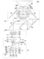
図6は、第3実施形態のプロジェクター1003の光学系を示す上面図である。図6において、第1実施形態の照明装置101と共通する構成要素については同じ符号を付し、詳細な説明は省略する。これらの構成要素については、必要に応じて図2及び図3を参照して説明を行う。
[Third Embodiment]
FIG. 6 is a top view showing the optical system of the projector 1003 of the third embodiment. In FIG. 6, the same reference numerals are given to components common to the illumination device 101 of the first embodiment, and detailed description thereof is omitted. These components will be described with reference to FIGS. 2 and 3 as necessary.

プロジェクター1003において第1実施形態のプロジェクター1001と異なるのは、照明装置103の構成である。色分離導光光学系200、光変調装置としての液晶光変調装置400R,液晶光変調装置400G,液晶光変調装置400B、クロスダイクロイックプリズム500及び投写光学系600の構成は第1実施形態のプロジェクター1001と同じである。   The projector 1003 is different from the projector 1001 of the first embodiment in the configuration of the illumination device 103. The configuration of the color separation light guide optical system 200, the liquid crystal light modulation device 400R as the light modulation device, the liquid crystal light modulation device 400G, the liquid crystal light modulation device 400B, the cross dichroic prism 500, and the projection optical system 600 is the projector 1001 of the first embodiment. Is the same.

第1実施形態の照明装置101では、光源装置10と第1レンズ23との間の光路上に、散乱微粒子を含有する樹脂の光拡散部材26を配置し、光拡散部材26によってレーザー光Lを拡散することで、蛍光層42上での励起光の光強度分布を均一化した。これに対して、第3実施形態の照明装置103では、散乱微粒子を含有する樹脂の光拡散部材26の代わりにホログラム素子からなる光拡散部材29によってレーザー光Lを拡散することで、励起光の光強度分布を均一化している。   In the illuminating device 101 of the first embodiment, a resin light diffusing member 26 containing scattered fine particles is disposed on the optical path between the light source device 10 and the first lens 23, and the laser light L is emitted by the light diffusing member 26. By diffusing, the light intensity distribution of the excitation light on the fluorescent layer 42 was made uniform. On the other hand, in the illumination device 103 of the third embodiment, the laser light L is diffused by the light diffusing member 29 made of a hologram element instead of the resin light diffusing member 26 containing the scattering fine particles, so that the excitation light The light intensity distribution is made uniform.

照明装置103は、光源装置10a、光源装置10b、光源装置10c集光光学系28、回転蛍光板30、モーター50、コリメート光学系60、第1レンズアレイ120、第2レンズアレイ130、偏光変換素子140及び重畳レンズ150を備えている。   The illumination device 103 includes a light source device 10a, a light source device 10b, a light source device 10c, a condensing optical system 28, a rotating fluorescent plate 30, a motor 50, a collimating optical system 60, a first lens array 120, a second lens array 130, and a polarization conversion element 140. And a superimposing lens 150.

集光光学系28は、第1レンズ23aと、第1レンズ23bと、第1レンズ23cと、光拡散部材29aと、光拡散部材29bと、光拡散部材29cと、第2レンズ25とを備えている。光拡散部材29aおよび第1レンズ23aは光源装置10aに対応して設けられ、光拡散部材29bおよび第1レンズ23bは光源装置10bに対応して設けられ、光拡散部材29cおよび第1レンズ23cは光源装置10cに対応して設けられている。集光光学系28は、光源装置10から回転蛍光板30までの光路中に配置され、光源装置10aから射出されるレーザー光Laと光源装置10bから射出されるレーザー光Lbと光源装置10cから射出されるレーザー光Lcとを略集光した状態で蛍光層42に入射させる。本明細書では、光拡散部材29aと光拡散部材29bと光拡散部材29cとをまとめて光拡散部材29と呼ぶことがある。   The condensing optical system 28 includes a first lens 23a, a first lens 23b, a first lens 23c, a light diffusing member 29a, a light diffusing member 29b, a light diffusing member 29c, and a second lens 25. ing. The light diffusing member 29a and the first lens 23a are provided corresponding to the light source device 10a, the light diffusing member 29b and the first lens 23b are provided corresponding to the light source device 10b, and the light diffusing member 29c and the first lens 23c are provided. It is provided corresponding to the light source device 10c. The condensing optical system 28 is disposed in the optical path from the light source device 10 to the rotating fluorescent plate 30, and is emitted from the laser light La emitted from the light source device 10a, the laser light Lb emitted from the light source device 10b, and the light source device 10c. The laser light Lc to be incident on the fluorescent layer 42 in a substantially condensed state. In this specification, the light diffusing member 29a, the light diffusing member 29b, and the light diffusing member 29c may be collectively referred to as the light diffusing member 29.

光拡散部材29は、例えば、ガラス基板に計算機で計算して人工的に作製した凹凸構造が形成された計算機合成ホログラム(Computer Generated Hologram; CGH)である。光拡散部材29は、光源装置10から射出されたレーザー光Lを拡散し、光強度分布が均一化された励起光を蛍光層42に入射させる。図6では、1つの光源装置10に対して1つの光拡散部材29を設けているが、光源装置10aと光源装置10bと光源装置10cに対して共通の1つの光拡散部材を設けることも可能である。   The light diffusing member 29 is, for example, a computer generated hologram (CGH) in which a concavo-convex structure artificially produced by calculation with a computer is formed on a glass substrate. The light diffusing member 29 diffuses the laser light L emitted from the light source device 10 and causes the excitation light having a uniform light intensity distribution to enter the fluorescent layer 42. In FIG. 6, one light diffusing member 29 is provided for one light source device 10, but it is also possible to provide one common light diffusing member for the light source device 10a, the light source device 10b, and the light source device 10c. It is.

計算機合成ホログラムは、回折現象を利用して入射光の波面を変換する波面変換素子である。特に位相変調型の計算機合成ホログラムは入射光波のエネルギーを殆ど失うことなく波面変換が可能である。計算機合成ホログラムは均一な光強度や単純な形状の光強度分布を発生させることが可能である。そのため、例えば、レーザー光Lの中心軸に跨って平坦部を有する光強度分布を形成することができ、これにより、均一性の高い光強度分布を実現することができる。   A computer-generated hologram is a wavefront conversion element that converts the wavefront of incident light using a diffraction phenomenon. In particular, a phase-modulated computer-generated hologram can be wavefront converted with almost no loss of incident light wave energy. The computer-generated hologram can generate a uniform light intensity or a light intensity distribution with a simple shape. Therefore, for example, a light intensity distribution having a flat portion across the central axis of the laser light L can be formed, and thereby a highly uniform light intensity distribution can be realized.

第1レンズ23はコリメートレンズであり、第2レンズ25は集光レンズである。第1レンズ23及び第2レンズ25は、例えば凸レンズからなる。   The first lens 23 is a collimating lens, and the second lens 25 is a condenser lens. The first lens 23 and the second lens 25 are, for example, convex lenses.

光源装置10aから射出されるレーザー光Laは、第1レンズ23a、光拡散部材29a及び第2レンズ25を介して蛍光層42上に集光され、光源装置10bから射出されるレーザー光Lbは、第1レンズ23b、光拡散部材29b及び第2レンズ25を介して蛍光層42上に集光され、光源装置10cから射出されるレーザー光Lcは、第1レンズ23c、光拡散部材29c及び第2レンズ25を介して蛍光層42上に集光される。光拡散部材29によってレーザー光Lが拡散されることで、レーザー光Lの光軸に垂直な平面内におけるレーザー光Lの光強度の分布が、光拡散部材29に入射する前よりも均一化される。   The laser light La emitted from the light source device 10a is condensed on the fluorescent layer 42 via the first lens 23a, the light diffusion member 29a, and the second lens 25, and the laser light Lb emitted from the light source device 10b is The laser light Lc collected on the fluorescent layer 42 via the first lens 23b, the light diffusion member 29b, and the second lens 25 and emitted from the light source device 10c is the first lens 23c, the light diffusion member 29c, and the second lens. The light is condensed on the fluorescent layer 42 through the lens 25. As the laser light L is diffused by the light diffusing member 29, the light intensity distribution of the laser light L in a plane perpendicular to the optical axis of the laser light L is made more uniform than before entering the light diffusing member 29. The

レーザー光La、レーザー光Lbおよびレーザー光Lcは、光拡散部材29によって均一化された後、蛍光層42上においてレーザー光Laのビームスポットとレーザー光Lbのビームスポットとレーザー光Lcのビームスポットとが互いに重なるように、第2レンズ25を介して蛍光層42上に照射される。このため、蛍光層42上における励起光の光強度分布は、光拡散部材29を用いない場合よりも均一化されている。ここで、蛍光層42上における励起光の高強度領域Cにおける光強度分布の均一性を高めるためには、蛍光層42上において、レーザー光Laのビームスポットとレーザー光Lbのビームスポットとレーザー光Lcのビームスポットとが互いにぴったり重なっていることが好ましい。   After the laser light La, the laser light Lb, and the laser light Lc are made uniform by the light diffusing member 29, the beam spot of the laser light La, the beam spot of the laser light Lb, and the beam spot of the laser light Lc on the fluorescent layer 42 Are irradiated onto the fluorescent layer 42 through the second lens 25 so as to overlap each other. For this reason, the light intensity distribution of the excitation light on the fluorescent layer 42 is made more uniform than when the light diffusion member 29 is not used. Here, in order to improve the uniformity of the light intensity distribution in the high intensity region C of the excitation light on the fluorescent layer 42, the beam spot of the laser light La, the beam spot of the laser light Lb, and the laser light on the fluorescent layer 42. It is preferable that the beam spot of Lc is exactly overlapped with each other.

このようにして、蛍光層42に照射される励起光の蛍光層42上での光強度分布が均一化され、蛍光層42上において突出して大きい光強度を有する部位が発生することが抑制される。そのため、励起用光源装置の出力を高くした時に起こる発光効率の低下が抑制され、明るい照明装置102が提供される。   In this way, the light intensity distribution on the fluorescent layer 42 of the excitation light applied to the fluorescent layer 42 is made uniform, and the occurrence of a portion having a large light intensity protruding on the fluorescent layer 42 is suppressed. . Therefore, a decrease in light emission efficiency that occurs when the output of the excitation light source device is increased is suppressed, and a bright illumination device 102 is provided.

[第4実施形態]
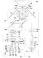
図7は、第4実施形態のプロジェクター1004の光学系を示す上面図である。図8は、プロジェクター1004に備えられる第2光源装置710の発光特性を示すグラフである。グラフの縦軸は相対発光強度を表し、発光強度が最も大きい波長における発光強度を1としている。グラフの横軸は波長を表す。図7において、第1実施形態のプロジェクター1001と共通する構成要素については同じ符号を付し、詳細な説明は省略する。これらの構成要素については、必要に応じて、図2、図3及び図4を参照して説明を行う。
[Fourth Embodiment]
FIG. 7 is a top view showing an optical system of the projector 1004 of the fourth embodiment. FIG. 8 is a graph showing the light emission characteristics of the second light source device 710 provided in the projector 1004. The vertical axis of the graph represents the relative light emission intensity, and the light emission intensity at the wavelength with the highest light emission intensity is 1. The horizontal axis of the graph represents the wavelength. In FIG. 7, components common to the projector 1001 of the first embodiment are denoted by the same reference numerals, and detailed description thereof is omitted. These components will be described with reference to FIGS. 2, 3 and 4 as necessary.

図7に示すように、プロジェクター1004は、照明装置104、第2照明装置700、色分離導光光学系202、光変調装置としての液晶光変調装置400R,液晶光変調装置400G,液晶光変調装置400B、クロスダイクロイックプリズム500及び投写光学系600を備えている。   As shown in FIG. 7, the projector 1004 includes an illumination device 104, a second illumination device 700, a color separation light guide optical system 202, a liquid crystal light modulation device 400R as a light modulation device, a liquid crystal light modulation device 400G, and a liquid crystal light modulation device. 400B, a cross dichroic prism 500, and a projection optical system 600 are provided.

第1実施形態のプロジェクター1001では、光源装置10から射出された青色光の一部を蛍光層から透過させて液晶光変調装置400Bの照明光として利用した。これに対して、第4実施形態のプロジェクター1004では、光源装置10から射出された青色光の全てを蛍光層46の励起光として利用し、液晶光変調装置400Bの照明光として利用する青色光は、照明装置104とは別個に設けられた第2照明装置700から射出される。   In the projector 1001 of the first embodiment, a part of the blue light emitted from the light source device 10 is transmitted through the fluorescent layer and used as illumination light for the liquid crystal light modulation device 400B. On the other hand, in the projector 1004 according to the fourth embodiment, all the blue light emitted from the light source device 10 is used as the excitation light for the fluorescent layer 46, and the blue light used as the illumination light for the liquid crystal light modulation device 400B is The light is emitted from a second lighting device 700 provided separately from the lighting device 104.

照明装置104は、光源装置10a、光源装置10b、光源装置10c、集光光学系21、回転蛍光板32、モーター50、コリメート光学系60、第1レンズアレイ120、第2レンズアレイ130、偏光変換素子140及び重畳レンズ150を備えている。光源装置10、集光光学系21、モーター50、コリメート光学系60、第1レンズアレイ120、第2レンズアレイ130、偏光変換素子140及び重畳レンズ150の構成は第1実施形態と同じであるため、詳細な説明は省略する。   The illumination device 104 includes a light source device 10a, a light source device 10b, a light source device 10c, a condensing optical system 21, a rotating fluorescent plate 32, a motor 50, a collimating optical system 60, a first lens array 120, a second lens array 130, and a polarization conversion element. 140 and a superimposing lens 150 are provided. The configurations of the light source device 10, the condensing optical system 21, the motor 50, the collimating optical system 60, the first lens array 120, the second lens array 130, the polarization conversion element 140, and the superimposing lens 150 are the same as in the first embodiment. Detailed description will be omitted.

回転蛍光板32はいわゆる透過型の回転蛍光板である。回転蛍光板32は、モーター50により回転可能な板材40の一部に、単一の蛍光層46が板材40の回転方向に沿って連続して形成されてなる。蛍光層46が形成されている領域は、励起光が入射する領域を含む。回転蛍光板32は、励起光(青色光)が入射する側とは反対側に向けて赤色光及び緑色光を射出する。   The rotating fluorescent plate 32 is a so-called transmission type rotating fluorescent plate. The rotating fluorescent plate 32 is formed by continuously forming a single fluorescent layer 46 along the rotation direction of the plate 40 on a part of the plate 40 that can be rotated by the motor 50. The region where the fluorescent layer 46 is formed includes a region where excitation light is incident. The rotating fluorescent plate 32 emits red light and green light toward the side opposite to the side on which excitation light (blue light) is incident.

回転蛍光板32は、使用時において7500rpmで回転する。詳しい説明は省略するが、回転蛍光板32の直径は50mmであり、回転蛍光板32に入射する励起光の光軸が回転蛍光板32の回転中心から約22.5mm離れた場所に位置するように構成されている。つまり、回転蛍光板32は、励起光の集光スポットが約18m/秒で蛍光層46上を移動するような回転速度で回転する。   The rotating fluorescent plate 32 rotates at 7500 rpm during use. Although a detailed description is omitted, the diameter of the rotating fluorescent plate 32 is 50 mm, and the optical axis of the excitation light incident on the rotating fluorescent plate 32 is located at a position about 22.5 mm away from the rotation center of the rotating fluorescent plate 32. ing. That is, the rotating fluorescent plate 32 rotates at such a rotational speed that the excitation light condensing spot moves on the fluorescent layer 46 at about 18 m / sec.

蛍光層46は励起光を透過し、蛍光層46から放射された蛍光を反射するダイクロイック膜44を介して板材40上に形成されている。ダイクロイック膜44は、例えば、誘電体多層膜からなる。   The fluorescent layer 46 is formed on the plate member 40 via a dichroic film 44 that transmits excitation light and reflects fluorescence emitted from the fluorescent layer 46. The dichroic film 44 is made of, for example, a dielectric multilayer film.

蛍光層46は、例えば、光源装置10から射出された励起光としてのレーザー光L(青色光)の略全てを赤色光及び緑色光を含む光に変換する。蛍光層46は、第1実施形態の蛍光層42よりも厚く形成されており、蛍光層46をそのまま通過する励起光は殆ど存在しない。蛍光層46は、波長が445nmの励起光によって効率的に励起され、光源装置10が射出する励起光を、図2(b)に示すように、赤色光及び緑色光を含む黄色の蛍光に変換して射出する。黄色の蛍光のうち、短波長側の成分は緑色光として利用され、黄色の蛍光のうち、長波長側の成分は赤色光として利用される。   For example, the fluorescent layer 46 converts substantially all of the laser light L (blue light) as excitation light emitted from the light source device 10 into light including red light and green light. The fluorescent layer 46 is formed thicker than the fluorescent layer 42 of the first embodiment, and there is almost no excitation light that passes through the fluorescent layer 46 as it is. The fluorescent layer 46 is efficiently excited by excitation light having a wavelength of 445 nm, and the excitation light emitted from the light source device 10 is converted into yellow fluorescence including red light and green light, as shown in FIG. And inject. Of the yellow fluorescence, the short wavelength component is used as green light, and among the yellow fluorescence, the long wavelength component is used as red light.

蛍光層46は、例えば、YAG系蛍光体である(Y,Gd)(Al,Ga)12:Ceを含有する層からなる。蛍光層46として、赤色光及び緑色光を含む蛍光を射出する他の蛍光体を含有する層を用いてもよい。また、蛍光層46として、励起光(青色光)を赤色光に変換する蛍光体と、励起光(青色光)を緑色光に変換する蛍光体との混合物を含有する層を用いてもよい。 The fluorescent layer 46 is made of a layer containing (Y, Gd) 3 (Al, Ga) 5 O 12 : Ce, which is a YAG phosphor, for example. As the fluorescent layer 46, a layer containing another phosphor that emits fluorescence including red light and green light may be used. Further, as the fluorescent layer 46, a layer containing a mixture of a phosphor that converts excitation light (blue light) into red light and a phosphor that converts excitation light (blue light) into green light may be used.

第1実施形態と同様に、光源装置10aから射出されるレーザー光Laは、光拡散部材26a、第1レンズ23a及び第2レンズ25を介して蛍光層46上に集光され、光源装置10bから射出されるレーザー光Lbは、光拡散部材26b、第1レンズ23b及び第2レンズ25を介して蛍光層46上に集光され、光源装置10cから射出されるレーザー光Lcは、光拡散部材26c、第1レンズ23c及び第2レンズ25を介して蛍光層46上に集光される。レーザー光Laとレーザー光Lbとレーザー光Lcとが、集光光学系21によって蛍光層46上において互いに重ね合わされることによって、蛍光層46を励起する励起光が形成される。   Similarly to the first embodiment, the laser light La emitted from the light source device 10a is condensed on the fluorescent layer 46 via the light diffusion member 26a, the first lens 23a, and the second lens 25, and is emitted from the light source device 10b. The emitted laser light Lb is condensed on the fluorescent layer 46 via the light diffusion member 26b, the first lens 23b, and the second lens 25, and the laser light Lc emitted from the light source device 10c is the light diffusion member 26c. The light is condensed on the fluorescent layer 46 through the first lens 23 c and the second lens 25. The laser light La, the laser light Lb, and the laser light Lc are superimposed on each other on the fluorescent layer 46 by the condensing optical system 21, thereby forming excitation light that excites the fluorescent layer 46.

光拡散部材26aはレーザー光Laを拡散させることによって、レーザー光Laの光強度分布を均一化する。光拡散部材26bはレーザー光Lbを拡散させることによって、レーザー光Lbの光強度分布を均一化する。光拡散部材26cはレーザー光Lcを拡散させることによって、レーザー光Lcの光強度分布を均一化する。これにより、蛍光層46に照射される励起光の蛍光層46上での光強度分布が均一化され、蛍光層46上において突出して大きい光強度を有する部位が発生することが抑制される。そのため、励起用光源装置の出力を高くした時に起こる発光効率の低下が抑制され、明るい照明装置104が提供される。   The light diffusing member 26a diffuses the laser light La to make the light intensity distribution of the laser light La uniform. The light diffusing member 26b diffuses the laser light Lb to make the light intensity distribution of the laser light Lb uniform. The light diffusing member 26c diffuses the laser light Lc to make the light intensity distribution of the laser light Lc uniform. Thereby, the light intensity distribution on the fluorescent layer 46 of the excitation light applied to the fluorescent layer 46 is made uniform, and the occurrence of a portion having a large light intensity protruding on the fluorescent layer 46 is suppressed. Therefore, a decrease in light emission efficiency that occurs when the output of the excitation light source device is increased is suppressed, and a bright illumination device 104 is provided.

第2照明装置700は、第2光源装置710、集光光学系720、散乱板730、偏光変換インテグレーターロッド740及び集光レンズ750を備えている。   The second illumination device 700 includes a second light source device 710, a condensing optical system 720, a scattering plate 730, a polarization conversion integrator rod 740, and a condensing lens 750.

第2光源装置710は、色光としてレーザー光からなる青色光(発光強度のピーク:約445nm、図8参照)を射出するレーザー光源である。図8において、符号Bで示すのは、第2光源装置710が青色光として射出する色光成分である。図7では光源装置710を1つ図示しているが、光源装置710の数はこれに限らず、複数個とすることも可能である。また、445nm以外の波長(例えば460nm)の青色光を射出する光源装置を用いることもできる。   The second light source device 710 is a laser light source that emits blue light (peak of emission intensity: about 445 nm, see FIG. 8) made of laser light as color light. In FIG. 8, reference numeral B indicates a color light component emitted by the second light source device 710 as blue light. Although one light source device 710 is illustrated in FIG. 7, the number of light source devices 710 is not limited to this, and a plurality of light source devices 710 may be used. A light source device that emits blue light having a wavelength other than 445 nm (for example, 460 nm) can also be used.

集光光学系720は、第1レンズ722及び第2レンズ724を備えている。集光光学系720は、全体として、青色光を略集光した状態で散乱板730に入射させる。第1レンズ722及び第2レンズ724は、例えば凸レンズからなる。   The condensing optical system 720 includes a first lens 722 and a second lens 724. As a whole, the condensing optical system 720 causes blue light to be incident on the scattering plate 730 in a substantially condensed state. The first lens 722 and the second lens 724 are, for example, convex lenses.

散乱板730は、第2光源装置710からの青色光を所定の散乱度で散乱し、蛍光(回転蛍光板33から射出される赤色光及び緑色光)に似た配光分布を有する青色光とする。散乱板730としては、例えば、光学ガラスからなる磨りガラスを用いることができる。   The scattering plate 730 scatters the blue light from the second light source device 710 with a predetermined degree of scattering to obtain blue light having a light distribution similar to fluorescence (red light and green light emitted from the rotating fluorescent plate 33). . As the scattering plate 730, for example, polished glass made of optical glass can be used.

偏光変換インテグレーターロッド740は、第2光源装置710からの青色光の面内光強度分布を均一にし、かつ、当該青色光を偏光方向の揃った略1種類の直線偏光光とする光学素子である。偏光変換インテグレーターロッド740は、詳しい説明は省略するが、インテグレーターロッドと、当該インテグレーターロッドの入射面側に配置され、青色光が入射する小孔を有する反射板と、射出面側に配置される反射型偏光板と、を備えている。   The polarization conversion integrator rod 740 is an optical element that makes the in-plane light intensity distribution of the blue light from the second light source device 710 uniform and makes the blue light approximately one type of linearly polarized light with the same polarization direction. . The polarization conversion integrator rod 740 is not described in detail, but the integrator rod, the reflector disposed on the incident surface side of the integrator rod, and having a small hole through which blue light is incident, and the reflection disposed on the exit surface side. A type polarizing plate.

なお、ロッドレンズを用いた偏光変換インテグレーターロッドの代わりに、レンズアレイを用いたレンズインテグレーター光学系及び偏光変換素子を用いることもできる。   A lens integrator optical system using a lens array and a polarization conversion element can also be used instead of the polarization conversion integrator rod using a rod lens.

集光レンズ750は、偏光変換インテグレーターロッド740からの光を集光して液晶光変調装置400Bの画像形成領域近傍に入射させる。   The condensing lens 750 condenses the light from the polarization conversion integrator rod 740 and causes it to enter the vicinity of the image forming area of the liquid crystal light modulator 400B.

色分離導光光学系202は、ダイクロイックミラー210、反射ミラー222,230,250を備えている。色分離導光光学系202は、照明装置102からの光を赤色光及び緑色光に分離し、照明装置102からの赤色光及び緑色光並びに第2照明装置700からの青色光のぞれぞれの色光を照明対象となる液晶光変調装置400R,液晶光変調装置400G,液晶光変調装置400Bに導光する機能を有する。色分離導光光学系200と液晶光変調装置400R,液晶光変調装置400G,液晶光変調装置40Bとの間には、集光レンズ300R,集光レンズ300G,集光レンズ300Bが配置されている。   The color separation light guide optical system 202 includes a dichroic mirror 210 and reflection mirrors 222, 230, and 250. The color separation light guide optical system 202 separates light from the illumination device 102 into red light and green light, and each of red light and green light from the illumination device 102 and blue light from the second illumination device 700. The color light is guided to the liquid crystal light modulation device 400R, the liquid crystal light modulation device 400G, and the liquid crystal light modulation device 400B to be illuminated. A condensing lens 300R, a condensing lens 300G, and a condensing lens 300B are disposed between the color separation light guide optical system 200 and the liquid crystal light modulation device 400R, the liquid crystal light modulation device 400G, and the liquid crystal light modulation device 40B. .

ダイクロイックミラー210を通過した赤色光は、反射ミラー230で反射され、集光レンズ300Rを通過して赤色光用の液晶光変調装置400Rの画像形成領域に入射する。ダイクロイックミラー210で反射された緑色光は、反射ミラー222でさらに反射され、集光レンズ300Gを通過して緑色光用液晶光変調装置400Gの画像形成領域に入射する。第2照明装置700からの青色光は、反射ミラー250で反射され、集光レンズ300Bを通過して青色光用の液晶光変調装置400Bの画像形成領域に入射する。   The red light that has passed through the dichroic mirror 210 is reflected by the reflecting mirror 230, passes through the condenser lens 300R, and enters the image forming area of the liquid crystal light modulation device 400R for red light. The green light reflected by the dichroic mirror 210 is further reflected by the reflection mirror 222, passes through the condenser lens 300G, and enters the image forming region of the green light liquid crystal light modulation device 400G. The blue light from the second illumination device 700 is reflected by the reflection mirror 250, passes through the condenser lens 300B, and enters the image forming region of the liquid crystal light modulation device 400B for blue light.

上記構成のプロジェクター1004によれば、光源装置10から射出された励起光によって蛍光層46が励起され、複数の色光が放射される。そのため、単一色の光源装置10を用いながら複数の色光を得ることができる。   According to the projector 1004 having the above configuration, the fluorescent layer 46 is excited by the excitation light emitted from the light source device 10, and a plurality of color lights are emitted. Therefore, a plurality of color lights can be obtained while using the single color light source device 10.

光拡散部材26aはレーザー光Laを拡散させることによって、レーザー光Laの光強度分布を均一化する。光拡散部材26bはレーザー光Lbを拡散させることによって、レーザー光Lbの光強度分布を均一化する。光拡散部材26cはレーザー光Lcを拡散させることによって、レーザー光Lcの光強度分布を均一化する。これにより、蛍光層46に照射される励起光の蛍光層46上での光強度分布が均一化され、蛍光層46上において突出して大きい光強度を有する部位が発生することが抑制される。また、蛍光層46は、モーター50により回転される板材40上に形成されているため、励起光の照射により生じた蛍光層46の熱は板材40の回転方向に沿った広い領域において放散される。そのため、励起用光源装置の出力を高くした時に起こる発光効率の低下が抑制され、明るい照明装置104が提供される。   The light diffusing member 26a diffuses the laser light La to make the light intensity distribution of the laser light La uniform. The light diffusing member 26b diffuses the laser light Lb to make the light intensity distribution of the laser light Lb uniform. The light diffusing member 26c diffuses the laser light Lc to make the light intensity distribution of the laser light Lc uniform. Thereby, the light intensity distribution on the fluorescent layer 46 of the excitation light applied to the fluorescent layer 46 is made uniform, and the occurrence of a portion having a large light intensity protruding on the fluorescent layer 46 is suppressed. Further, since the fluorescent layer 46 is formed on the plate member 40 rotated by the motor 50, the heat of the fluorescent layer 46 generated by the irradiation of the excitation light is dissipated in a wide region along the rotation direction of the plate member 40. . Therefore, a decrease in light emission efficiency that occurs when the output of the excitation light source device is increased is suppressed, and a bright illumination device 104 is provided.

[変形形態]
第4実施形態のプロジェクターでは、液晶光変調装置400B用の照明光源として、第2照明装置を別個に設けたが、このような構成は、第1乃至第3実施形態のプロジェクターにも適用することができる。
[Deformation]
In the projector of the fourth embodiment, the second illumination device is separately provided as the illumination light source for the liquid crystal light modulation device 400B. However, such a configuration is also applicable to the projectors of the first to third embodiments. Can do.

第1乃至第4実施形態の照明装置は、光源装置10a、光源装置10b、光源装置10cと、少なくとも1つの光拡散部材を備えており、レーザー光Laとレーザー光Lbとレーザー光Lcとが、蛍光層に入射する前に均一化されている。すべてのレーザー光Lを均一化するほうが好ましいが、必ずしもすべてのレーザー光Lを均一化する必要はない。   The illumination devices of the first to fourth embodiments include a light source device 10a, a light source device 10b, a light source device 10c, and at least one light diffusing member. The laser light La, the laser light Lb, and the laser light Lc are It is made uniform before entering the fluorescent layer. Although it is preferable to make all the laser beams L uniform, it is not always necessary to make all the laser beams L uniform.

回転蛍光板に形成する蛍光層として、青色の励起光によって赤色光と緑色光を放射する例を説明したが、蛍光層はこのようなものに限定されない。例えば、紫色光又は紫外光を励起光として用い、該励起光によって赤色光、緑色光及び青色光の3つの色光を放射する蛍光層を用いてもよい。   Although the example which radiates | emits red light and green light by blue excitation light was demonstrated as a fluorescent layer formed in a rotation fluorescent plate, a fluorescent layer is not limited to such a thing. For example, a fluorescent layer that uses violet light or ultraviolet light as excitation light and emits three color lights of red light, green light, and blue light by the excitation light may be used.

蛍光層として、板材の回転方向に沿って連続して形成される例を説明したが、蛍光層の構成はこれに限定されない。特許文献1の回転蛍光板のように、板材の回転方向に沿って複数種類の蛍光層を形成し、複数の色光を順次発光可能な構成としてもよい。回転蛍光板から順次発光された複数の色光は1つの光変調装置によって変調され、カラー画像を形成する。   Although the example in which the fluorescent layer is continuously formed along the rotation direction of the plate material has been described, the configuration of the fluorescent layer is not limited thereto. As in the rotating fluorescent plate of Patent Document 1, a plurality of types of fluorescent layers may be formed along the rotation direction of the plate material, and a plurality of color lights may be sequentially emitted. A plurality of color lights sequentially emitted from the rotating fluorescent plate are modulated by one light modulation device to form a color image.

このような回転蛍光板においても、複数の光源装置10から射出された複数の励起光の光強度分布を均一化して蛍光層上に集光する集光光学系を備えることにより、蛍光層上において突出して大きい光強度を有する部位が発生することが抑制される。これにより、励起用光源装置の出力を高くした時に起こる発光効率の低下が抑制され、明るい照明装置が提供される。   Such a rotating fluorescent plate also has a condensing optical system that makes the light intensity distribution of a plurality of excitation lights emitted from a plurality of light source devices 10 uniform and collects the light on the fluorescent layer, thereby protruding on the fluorescent layer. Generation of a portion having a large light intensity is suppressed. This suppresses a decrease in light emission efficiency that occurs when the output of the excitation light source device is increased, and provides a bright illumination device.

10…光源装置、21,27,28…集光光学系、26,26a,26b,26c,41,29,29a,29b,29c…光拡散部材、23,23a,23b,23c…第1レンズ(コリメートレンズ)、25…第2レンズ(集光レンズ)、40…板材、42,46…蛍光層、50…モーター、101,102,103,104…照明装置、400R,400G,400B…光変調装置、600…投写光学系、1001,1002,1003,1004…プロジェクター、BS…蛍光層上における励起光のビームスポット、C…高強度領域、D…減衰領域 DESCRIPTION OF SYMBOLS 10 ... Light source device, 21, 27, 28 ... Condensing optical system, 26, 26a, 26b, 26c, 41, 29, 29a, 29b, 29c ... Light diffusion member, 23, 23a, 23b, 23c ... 1st lens ( Collimating lens), 25 ... second lens (condensing lens), 40 ... plate material, 42, 46 ... fluorescent layer, 50 ... motor, 101, 102, 103, 104 ... illumination device, 400R, 400G, 400B ... light modulation device , 600 ... projection optical system, 1001, 1002, 1003, 1004 ... projector, BS ... beam spot of excitation light on the fluorescent layer, C ... high intensity region, D ... attenuation region

Claims (8)

第1の光を射出する第1の光源装置と、
第2の光を射出する第2の光源装置と、
前記第1の光及び前記第2の光によって励起される蛍光層と、
前記第1の光源装置と前記蛍光層との間の前記第1の光の光路上に配置され、前記第1の光を拡散させる光拡散部材と、
前記第1の光の少なくとも一部と前記第2の光の少なくとも一部とが前記蛍光層上において互いに重なりあうように、前記第1の光と前記第2の光とを前記蛍光層に照射する集光光学系と、を備えていることを特徴とする照明装置。
A first light source device that emits first light;
A second light source device that emits second light;
A fluorescent layer excited by the first light and the second light;
A light diffusing member disposed on an optical path of the first light between the first light source device and the fluorescent layer and diffusing the first light;
Irradiating the fluorescent layer with the first light and the second light so that at least part of the first light and at least part of the second light overlap each other on the fluorescent layer. And an optical condensing optical system.
前記集光光学系は、前記光拡散部材によって拡散された前記第1の光が入射するコリメートレンズと、前記コリメートレンズから射出された前記第1の光が入射する集光レンズと、を備えていることを特徴とする請求項1に記載の照明装置。   The condensing optical system includes a collimating lens on which the first light diffused by the light diffusing member is incident, and a condensing lens on which the first light emitted from the collimating lens is incident. The lighting device according to claim 1, wherein: 前記光拡散部材は、ホログラム素子であることを特徴とする請求項1または2に記載の照明装置。   The illumination device according to claim 1, wherein the light diffusion member is a hologram element. 前記光拡散部材によって拡散された前記第1の光の光強度分布は、前記第1の光の中心軸にまたがって平坦部を有する光強度分布であることを特徴とする請求項3に記載の照明装置。   The light intensity distribution of the first light diffused by the light diffusing member is a light intensity distribution having a flat portion across a central axis of the first light. Lighting device. 前記光拡散部材は、前記蛍光層が一面側に形成された板材であることを特徴とする請求項1乃至4のいずれか1項に記載の照明装置。   The lighting device according to claim 1, wherein the light diffusing member is a plate material on which the fluorescent layer is formed on one surface side. 前記蛍光層は、モーターにより回転される板材上に、前記板材の回転方向に沿って連続して形成されていることを特徴とする請求項1乃至5のいずれか1項に記載の照明装置。   The lighting device according to claim 1, wherein the fluorescent layer is continuously formed on a plate member rotated by a motor along a rotation direction of the plate member. 前記第1の光源装置は、前記第1の光としてレーザー光を射出するレーザー光源であり、前記第2の光源装置は、前記第2の光としてレーザー光を射出するレーザー光源であることを特徴とする請求項1乃至6のいずれか1項に記載の照明装置。   The first light source device is a laser light source that emits laser light as the first light, and the second light source device is a laser light source that emits laser light as the second light. The illumination device according to any one of claims 1 to 6. 請求項1乃至7のいずれか1項に記載の照明装置と、
前記照明装置からの照明光を画像情報に応じて変調する光変調装置と、
前記光変調装置からの変調光を投写画像として投写する投写光学系と、を備えていることを特徴とするプロジェクター。
The lighting device according to any one of claims 1 to 7,
A light modulation device that modulates illumination light from the illumination device according to image information;
And a projection optical system that projects the modulated light from the light modulation device as a projection image.
JP2010254026A 2010-11-12 2010-11-12 Illumination device and projector Pending JP2012103615A (en)

Priority Applications (1)

Application Number Priority Date Filing Date Title
JP2010254026A JP2012103615A (en) 2010-11-12 2010-11-12 Illumination device and projector

Applications Claiming Priority (1)

Application Number Priority Date Filing Date Title
JP2010254026A JP2012103615A (en) 2010-11-12 2010-11-12 Illumination device and projector

Publications (1)

Publication Number Publication Date
JP2012103615A true JP2012103615A (en) 2012-05-31

Family

ID=46394039

Family Applications (1)

Application Number Title Priority Date Filing Date
JP2010254026A Pending JP2012103615A (en) 2010-11-12 2010-11-12 Illumination device and projector

Country Status (1)

Country Link
JP (1) JP2012103615A (en)

Cited By (14)

* Cited by examiner, † Cited by third party
Publication number Priority date Publication date Assignee Title
JP2012215633A (en) * 2011-03-31 2012-11-08 Casio Comput Co Ltd Light source device and projector
JP2013092752A (en) * 2011-10-06 2013-05-16 Panasonic Corp Light source device and image display apparatus
WO2013187145A1 (en) * 2012-06-15 2013-12-19 ウシオ電機株式会社 Phosphor light source device
JP2014010181A (en) * 2012-06-27 2014-01-20 Ricoh Co Ltd Light source device and projecting device
WO2014196015A1 (en) * 2013-06-04 2014-12-11 Necディスプレイソリューションズ株式会社 Illumination optical system and projector
EP3035119A1 (en) * 2014-12-15 2016-06-22 Nichia Corporation Light source apparatus and projector having light source apparatus
EP2919068A4 (en) * 2012-11-06 2016-07-06 Sony Corp Light source unit, light source device, and image display device
JP2017083907A (en) * 2017-02-07 2017-05-18 Necディスプレイソリューションズ株式会社 Projector and method for irradiating image forming element with illumination light
KR20170090123A (en) * 2016-01-28 2017-08-07 엘지이노텍 주식회사 Object directed emitting device and optical module
WO2017215348A1 (en) * 2016-06-14 2017-12-21 深圳市绎立锐光科技开发有限公司 Outgoing-light uniformity adjustment apparatus of projection light source system and projection device
US9860497B2 (en) 2015-02-17 2018-01-02 Seiko Epson Corporation Illumination device and projector
US9964845B2 (en) 2014-07-23 2018-05-08 Dai Nippon Printing Co., Ltd. Projection apparatus and illumination apparatus
US9983470B2 (en) 2015-12-14 2018-05-29 Seiko Epson Corporation Light source device and projector
US10768517B2 (en) 2015-03-09 2020-09-08 Seiko Epson Corporation Light source device and projector

Cited By (22)

* Cited by examiner, † Cited by third party
Publication number Priority date Publication date Assignee Title
JP2012215633A (en) * 2011-03-31 2012-11-08 Casio Comput Co Ltd Light source device and projector
JP2013092752A (en) * 2011-10-06 2013-05-16 Panasonic Corp Light source device and image display apparatus
WO2013187145A1 (en) * 2012-06-15 2013-12-19 ウシオ電機株式会社 Phosphor light source device
JP2014010181A (en) * 2012-06-27 2014-01-20 Ricoh Co Ltd Light source device and projecting device
EP2919068A4 (en) * 2012-11-06 2016-07-06 Sony Corp Light source unit, light source device, and image display device
US9625800B2 (en) 2012-11-06 2017-04-18 Sony Corporation Light source, light source apparatus, and image display apparatus to facilitate cooling and handling of the light source
JPWO2014196015A1 (en) * 2013-06-04 2017-02-23 Necディスプレイソリューションズ株式会社 Illumination optical system and projector
CN105122133B (en) * 2013-06-04 2016-10-19 Nec显示器解决方案株式会社 Lamp optical system and projector
CN105122133A (en) * 2013-06-04 2015-12-02 Nec显示器解决方案株式会社 Illumination optical system and projector
WO2014196015A1 (en) * 2013-06-04 2014-12-11 Necディスプレイソリューションズ株式会社 Illumination optical system and projector
US9964845B2 (en) 2014-07-23 2018-05-08 Dai Nippon Printing Co., Ltd. Projection apparatus and illumination apparatus
CN105700279A (en) * 2014-12-15 2016-06-22 日亚化学工业株式会社 Light source apparatus and projector having light source apparatus
EP3035119A1 (en) * 2014-12-15 2016-06-22 Nichia Corporation Light source apparatus and projector having light source apparatus
CN105700279B (en) * 2014-12-15 2020-06-09 日亚化学工业株式会社 Light source device and projector including the same
US9807355B2 (en) 2014-12-15 2017-10-31 Nichia Corporation Light source apparatus and projector having light source apparatus
US9860497B2 (en) 2015-02-17 2018-01-02 Seiko Epson Corporation Illumination device and projector
US10768517B2 (en) 2015-03-09 2020-09-08 Seiko Epson Corporation Light source device and projector
US9983470B2 (en) 2015-12-14 2018-05-29 Seiko Epson Corporation Light source device and projector
KR20170090123A (en) * 2016-01-28 2017-08-07 엘지이노텍 주식회사 Object directed emitting device and optical module
KR102585118B1 (en) 2016-01-28 2023-10-05 엘지이노텍 주식회사 Object directed emitting device and optical module
WO2017215348A1 (en) * 2016-06-14 2017-12-21 深圳市绎立锐光科技开发有限公司 Outgoing-light uniformity adjustment apparatus of projection light source system and projection device
JP2017083907A (en) * 2017-02-07 2017-05-18 Necディスプレイソリューションズ株式会社 Projector and method for irradiating image forming element with illumination light

Similar Documents

Publication Publication Date Title
JP2012103615A (en) Illumination device and projector
JP5617288B2 (en) Lighting device and projector
JP5601092B2 (en) Lighting device and projector
US8998421B2 (en) Projector having polarization conversion
JP6019891B2 (en) Light source device and projector
US9563109B2 (en) Light source device with wavelength conversion element and projector including the same
JP5682813B2 (en) Lighting device and projector
JP5659775B2 (en) Light source device and projector
JP2012108486A (en) Light source device and image display
JP2012128121A (en) Illumination device and projector
JP2018028647A (en) Wavelength conversion element, light source device, and projector
JP2012142222A (en) Light source device and projector
US20130286360A1 (en) Projector
JP2012194268A (en) Diffuser plate, light source device, and projector
JP2016099566A (en) Wavelength conversion element, light source unit and projector
JP2019045778A (en) Wavelength conversion element, light source device, and projector
JP2012063488A (en) Light source device and projector
CN107436529B (en) Light source device and projection display device
JP6550781B2 (en) Light source device and projector
JP5803447B2 (en) Light source device and projector
JP5991389B2 (en) Lighting device and projector
JP2017146552A (en) Illumination device and projector
JP5733376B2 (en) projector
JP2016114728A (en) Wavelength conversion member and image forming apparatus
JP5949984B2 (en) Light source device and projector