JP2012103175A - Electrically-driven power steering device - Google Patents
Electrically-driven power steering device Download PDFInfo
- Publication number
- JP2012103175A JP2012103175A JP2010253229A JP2010253229A JP2012103175A JP 2012103175 A JP2012103175 A JP 2012103175A JP 2010253229 A JP2010253229 A JP 2010253229A JP 2010253229 A JP2010253229 A JP 2010253229A JP 2012103175 A JP2012103175 A JP 2012103175A
- Authority
- JP
- Japan
- Prior art keywords
- torque
- detection
- detection coils
- power steering
- pairs
- Prior art date
- Legal status (The legal status is an assumption and is not a legal conclusion. Google has not performed a legal analysis and makes no representation as to the accuracy of the status listed.)
- Granted
Links
Images


Abstract
Description
本発明は、自動車や車両の操舵系にモータによる操舵補助力を付与するようにした電動パワーステアリング装置に関し、より詳細には、回転軸に発生するトルクを検出するトルクセンサに関する。 The present invention relates to an electric power steering apparatus that applies a steering assist force by a motor to a steering system of an automobile or a vehicle, and more particularly to a torque sensor that detects torque generated on a rotating shaft.
従来より、電動パワーステアリング装置のトルク検出手段として用いられる非接触型のトルクセンサとしては、例えば特許文献1に開示されているものが知られている。このトルクセンサでは、トルクに比例したトーションバーの捩れを検出コイルのインダクタンスの変化に変換し、インダクタンスの変化を1対の検出コイル及び抵抗体で構成するブリッジ回路で検出している。即ち、1対の検出コイル及び抵抗体で構成する第1のアーム及び第2のアームを備えたブリッジ回路に交流電圧を供給し、第1のアームの検出コイル及び抵抗体の接続部に表れる出力電圧と、第2のアームの検出コイル及び抵抗体の接続部に表れる出力電圧との差分の電圧を差動増幅器で検出し、トルク信号を得るように構成されている。 Conventionally, as a non-contact type torque sensor used as torque detection means of an electric power steering device, for example, one disclosed in Patent Document 1 is known. In this torque sensor, the twist of the torsion bar proportional to the torque is converted into a change in inductance of the detection coil, and the change in inductance is detected by a bridge circuit constituted by a pair of detection coils and resistors. That is, an AC voltage is supplied to a bridge circuit including a first arm and a second arm configured by a pair of detection coils and resistors, and an output appears at a connection portion of the detection coils and resistors of the first arm. The differential voltage between the voltage and the output voltage appearing at the connection between the detection coil of the second arm and the resistor is detected by a differential amplifier to obtain a torque signal.
しかしながら、上記特許文献1に記載のトルクセンサは、プリント配線基板の上に1対の検出コイル及び抵抗体がブリッジ回路を構成するように接続されている。検出コイルとプリント配線基板とはハンダ付けなどで接続されるが、ハンダ付け不良など接続が確実になされていないと、検出コイルや抵抗体とプリント配線基板との間に接触抵抗が生じ、不正確なトルク信号が出力されてしまうという不都合がある。 However, in the torque sensor described in Patent Document 1, a pair of detection coils and resistors are connected on a printed wiring board so as to form a bridge circuit. The detection coil and printed wiring board are connected by soldering, etc., but if the connection is not made securely due to poor soldering, contact resistance is generated between the detection coil or resistor and the printed wiring board, which is inaccurate. There is a disadvantage that a large torque signal is output.
かかる不都合を解決しつつ、近年の電動パワーステアリング装置の大型化に対応できるようにしたものとして、例えば特許文献2に示されるトルクセンサがある。このトルクセンサでは、1対の検出コイル及び抵抗で成るブリッジ回路に対して、2系統の全く同一の検出回路が冗長的に接続されている。これにより、異常を容易に検出可能にするとともに、検出回路の一方で異常を生じても、他方の検出回路からのトルク信号によって操舵アシストを継続できるようになっている。 For example, Patent Document 2 discloses a torque sensor that can cope with the recent increase in size of an electric power steering apparatus while solving such inconvenience. In this torque sensor, two identical detection circuits are redundantly connected to a bridge circuit composed of a pair of detection coils and resistors. As a result, the abnormality can be easily detected, and even if an abnormality occurs in one of the detection circuits, the steering assist can be continued by the torque signal from the other detection circuit.
しかしながら、上述した特許文献2のトルクセンサは、それぞれがコイルヨークに内包された4つのコイルが軸方向に沿って配される構成になっていた。そのため、トルクセンサの軸方向におけるレイアウトが制限されてしまうという問題があった。 However, the above-described torque sensor disclosed in Patent Document 2 has a configuration in which four coils, each included in a coil yoke, are arranged along the axial direction. Therefore, there is a problem that the layout of the torque sensor in the axial direction is limited.
また、上記した特許文献2のトルクセンサは、4つのコイルからなる構成とすることにより、個々のコイルに作用する磁気バランスのバラツキが2つのコイルからなる構成の場合よりも大きくなってしまい、トルク検出感度にバラツキが生じてしまうという問題があった。 In addition, the torque sensor of Patent Document 2 described above has a configuration including four coils, so that the variation in magnetic balance acting on each coil becomes larger than in the configuration including two coils. There has been a problem that the detection sensitivity varies.
本発明は、上記事情に鑑みてなされたものであり、その目的とするところは、トルクセンサの高い信頼性を維持しつつ、上述したような従来からあった未解決の課題を解消した電動パワーステアリング装置を提供することにある。 The present invention has been made in view of the above circumstances, and an object of the present invention is to provide an electric power that eliminates the above-described unsolved problems as described above while maintaining high reliability of the torque sensor. The object is to provide a steering device.
本発明の上記目的は、回転軸に生じるトルクに応じて互いに逆方向にインピーダンスが変化する2対の検出コイルと、前記2対の検出コイルのそれぞれに直列接続された抵抗体とで成る2つのブリッジ回路にそれぞれ交流信号を印加し、前記各ブリッジ回路の差分信号に基づいて前記トルクを検出するトルクセンサを具備した電動パワーステアリング装置であって、前記2対の検出コイルが、それぞれ2つの検出コイルで1つのヨークを共用するように該ヨークに内包されていることを特徴とする電動パワーステアリング装置により、達成される。 The above-mentioned object of the present invention is to provide two detection coils comprising two pairs of detection coils whose impedances change in opposite directions according to the torque generated on the rotating shaft, and resistors connected in series to the two pairs of detection coils. An electric power steering apparatus including a torque sensor that applies an AC signal to each bridge circuit and detects the torque based on a difference signal of each bridge circuit, wherein the two detection coils each detect two This is achieved by an electric power steering device characterized in that the coil is included in the yoke so as to share one yoke.
また、本発明の上記目的は、回転軸に生じるトルクに応じて互いに逆方向にインピーダンスが変化する2対の検出コイルと、前記2対の検出コイルのそれぞれに直列接続された抵抗体とで成る2つのブリッジ回路にそれぞれ交流信号を印加し、前記各ブリッジ回路の差分信号に基づいて前記トルクを検出するトルクセンサを具備した電動パワーステアリング装置であって、前記2対の検出コイルを内包するヨークの周囲には、磁気シールド材が配設されていることを特徴とする電動パワーステアリング装置により、達成される。 The above-mentioned object of the present invention is composed of two pairs of detection coils whose impedances change in opposite directions according to the torque generated on the rotating shaft, and resistors connected in series to the two pairs of detection coils. An electric power steering apparatus including a torque sensor that applies an AC signal to each of two bridge circuits and detects the torque based on a difference signal of each of the bridge circuits, the yoke including the two pairs of detection coils This is achieved by an electric power steering device characterized in that a magnetic shield material is disposed around the motor.
本発明に係る電動パワーステアリング装置によれば、トルクセンサを構成する2対の検出コイルが、それぞれ2つの検出コイルで1つのヨークを共用するように該ヨークに内包されているので、検出コイルを設置するための軸方向寸法を2コイルの場合と同等に保ったまま、4コイルの構成を実現することができる。その結果、トルクセンサの軸方向におけるレイアウトの自由度を向上させることができる。 According to the electric power steering apparatus of the present invention, the two pairs of detection coils constituting the torque sensor are included in the yoke so that each of the two detection coils shares one yoke. A 4-coil configuration can be realized while maintaining the axial dimensions for installation to be the same as in the case of 2-coils. As a result, the degree of freedom of layout in the axial direction of the torque sensor can be improved.
また、本発明に係る電動パワーステアリング装置によれば、2対の検出コイルを内包するヨークの周囲に磁気シールド材が配設されているので、4コイル構成時に生じ易くなっていた磁気バランスのバラツキを防止することができ、その結果、トルク検出感度を安定させることができる。 Further, according to the electric power steering apparatus of the present invention, since the magnetic shield material is disposed around the yoke containing the two pairs of detection coils, the magnetic balance variation that is likely to occur when the four-coil configuration is formed. As a result, torque detection sensitivity can be stabilized.
以下、本発明に係る電動パワーステアリング装置の実施形態について、図面を参照にしながら説明する。 DESCRIPTION OF EMBODIMENTS Hereinafter, embodiments of an electric power steering apparatus according to the present invention will be described with reference to the drawings.
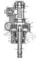
図1は、本発明の第1実施形態に係る電動パワーステアリング装置の主要部構造を示す断面図であり、図2は、本発明の第1実施形態に係る電動パワーステアリング装置のトルクセンサを示す斜視図である。 FIG. 1 is a cross-sectional view showing the main structure of the electric power steering apparatus according to the first embodiment of the present invention, and FIG. 2 shows the torque sensor of the electric power steering apparatus according to the first embodiment of the present invention. It is a perspective view.
入力軸側及び出力軸側に2分割された構造になっているハウジング5a及び5bの内部には入力軸1が配され、円筒状の入力軸1の内部に配置されたトーションバー3と、トーションバー3を介して入力軸1に連結された出力軸2とが軸受6a,6b及び6cによって回転自在に支持されている。入力軸1、トーションバー3及び出力軸2は同軸に配置されており、入力軸1とトーションバー3とは例えばピン結合され、トーションバー3と出力軸2は例えばスプライン結合されている。入力軸1の左端側にはステアリングホイール(図示せず)が一体的に取り付けられ、出力軸2にはピニオン軸2aが一体的に形成されており、ピニオン軸2aはラック4と噛合して公知のラックアンドピニオン式ステアリング機構を構成している。また、出力軸2には、これと同軸で且つ一体に回転するウォームホイール7が固着されており、モータ(図示せず)で駆動されるウォーム8と噛合している。
An input shaft 1 is arranged inside the
モータの回転力は、ウォーム8及びウォームホイール7を介して出力軸2に伝達され、モータの回転方向を適宜切り換えることにより、出力軸2に任意の方向の操舵アシストが付与される。
The rotational force of the motor is transmitted to the output shaft 2 via the worm 8 and the
トルクセンサは図1に示す入力軸1の右端外側に同軸に配設されており、トルクセンサのトルク検出部は図2に詳細を示すように、入力軸1の右端側に形成されたセンサシャフト部11と、ハウジング5aの内側に配置された2対の検出コイル131,141及び検出コイル132、142と、両者の間に配置された円筒部材12とで構成される。
The torque sensor is coaxially disposed outside the right end of the input shaft 1 shown in FIG. 1, and the torque detector of the torque sensor is a sensor shaft formed on the right end side of the input shaft 1 as shown in detail in FIG.
入力軸1の右端に近い外側には磁性材料で構成されたセンサシャフト部11が形成されており、センサシャフト部11の表面には、軸方向に延びた複数の凸条11aが円周方向に沿って等間隔に形成されており、凸条11aの間には凸条11aの幅t1よりも幅広の溝部11bが形成されている。
A
また、センサシャフト部11の外側には、センサシャフト部11に接近して導電性で且つ非磁性の材料、例えばアルミニウムで構成された円筒部材12がセンサシャフト部11と同軸に配置されており、円筒部材12の延長部12eは出力軸2の端部2eの外側に固定されている。円筒部材12には、センサシャフト部11の表面の凸条11aに対向する位置に、円周方向に等間隔に配置された複数個の長方形の窓12aで成る第1の窓列と、第1の窓列からそれぞれ軸方向にずれた位置に窓12aと同一形状で、円周方向の位相が異なる複数個の長方形の窓12bで成る第2の窓列とが設けられている。
Further, on the outside of the
円筒部材12の外周は、同一規格の検出コイル131、141及び132、142が巻回されたヨーク151及び152で包囲されている。即ち、検出コイル131,141及び132、142は円筒部材12と同軸に配置され、検出コイル131及び132は窓12aで成る第1の窓列部分を包囲し、検出コイル141及び142は窓12bで成る第2の窓列部分を包囲する。また、検出コイル131、141は、ヨーク151を共用するように該ヨーク151に内包され、かつ、検出コイル132、142は、ヨーク152を共用するように該ヨーク152に内包されている。ヨーク151及び152はハウジング5aの内部に固定され、検出コイル131,141及び132、142の出力線はハウジング5aの内部に配置された回路基板200に接続されている。回路基板200には、後述するトルク検出回路が装着されている。
The outer periphery of the
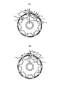
図3(A)及び(B)はセンサシャフト部11の表面の凸条11aと円筒部材12の窓12a,12bの配置を説明するための図であり、図3(A)は、基準位置(トーションバー3が捩れていない状態)におけるセンサシャフト部11の表面の凸条11aと円筒部材12の窓12aとの位置関係を示し、図3(B)は基準位置(トーションバー3が捩れていない状態)におけるセンサシャフト部11の表面の凸条11aと円筒部材12の窓12bとの位置関係を示す図である。本実施例では、窓12a及び12bがそれぞれ9個設けられているから、窓12a及び12bはそれぞれ円周方向に角度θ=360/N度(図3の例では角度θ=360/9=40度)ずつズレていることになる。
FIGS. 3A and 3B are views for explaining the arrangement of the
窓12a、12bの角度aは窓12a、12bのない部分の角度bよりも小さく設定(a<b)され、凸条11aの角度cは溝部11bの角度dよりも小さく設定(c<d)される。これは、検出コイルのインピーダンスの変化を急峻にするためである。
The angle a of the
図3から明らかなように、トーションバー3が捩れていない状態、即ち操舵トルクが0の状態では、窓12aの円周方向の中央部に凸条11aの円周方向の一方の端部が位置し、窓12bの円周方向の中央部に凸条11aの円周方向の他方の端部が位置するように、窓12a及び12bの円周方向の幅と凸条11aの幅、及び窓12a及び12bとの円周方向の相対位置関係が設定される。即ち、凸条11aに対する窓12a及び12bの円周方向の位置関係は互いに逆になっている。
As is apparent from FIG. 3, when the
操舵系が直進状態にあって操舵トルクが0である場合はトーションバー3には捩れが発生せず、入力軸1と出力軸2とは相対回転しない。従って、入力軸1側にあるセンサシャフト部11の表面の凸条11aと、出力軸2の側にある円筒部材12との間にも相対回転が生じない。
When the steering system is in the straight traveling state and the steering torque is 0, the
一方、ステアリングホイールを操作して入力軸1に回転力が加わると、その回転力はトーションバー3を経て出力軸2に伝達される。このとき、出力軸2には舵輪と路面との間の摩擦力や出力軸2に結合されているステアリング機構の摩擦力が作用するので、入力軸1と出力軸2との間を結合するトーションバーに捩れが発生し、入力軸1の側にあるセンサシャフト部11の表面の凸条11aと出力軸2の側にある円筒部材12との間に相対回転が生ずる。
On the other hand, when a rotational force is applied to the input shaft 1 by operating the steering wheel, the rotational force is transmitted to the output shaft 2 via the
なお、円筒部材12に窓がない場合は、円筒部材12は導電性で且つ非磁性材で構成されているから、検出コイル131、141及び132、142に交流電流を流して交番磁界を発生させると、円筒部材12の外周面にコイル電流と反対方向の渦電流が発生する。この渦電流による磁界とコイル電流による磁界とを重畳すると、円筒部材12の内側の磁界は相殺される。
When the
円筒部材12に窓が形成されている場合は、円筒部材12の外周面に発生した渦電流は、窓12a及び12bによって外周面を周回できないため、窓12a及び12bの端面に沿って円筒部材12の内周面側に回り込み、内周面をコイル電流と同方向に流れ、また隣の窓12a及び12bの端面に沿って外周面側に戻り、ループを形成する。つまり、検出コイル内側に渦電流のループを、円周方向に周期的に配置した状態が発生する。コイル電流による磁界と渦電流による磁界とは重畳され、円筒部材12の内外には、円周方向に周期的に強弱変化する磁界と、中心に向かうほど小さくなる半径方向に勾配を持った磁界が形成される。円周方向の周期的な磁界の強弱は、隣り合う渦電流の影響を受ける窓12a及び12bの中心で強く、そこからずれるに従い弱くなる。
When a window is formed in the
円筒部材12の内側には、磁性材料で成るセンサシャフト部11が同軸に配置されており、その凸条11aは窓12a及び12bと同じ周期で配置されている。磁界中に置かれた磁性体は磁化して磁束を生ずるが、磁束の量は飽和するまでは磁界の強さに応じて大きくなる。このため、円筒部材12により円周方向の周期的な磁界の強弱と、中心に向かうほど小さくなる半径方向に勾配を持った磁界とにより、センサシャフト部11に発生する磁束は、円筒部材12とセンサシャフト部11との相対的な位相により増減する。磁束が最大となる位相は、円筒部材12の窓12a及び12bの中心とセンサシャフト部11の凸条11aの中心とが一致した状態で、磁束の増減に応じて検出コイル131、141及び132、142のインダクタンスも増減してほぼ正弦波状に変化する。
A
トルクが作用しない状態では、インダクタンスが最大となる位相に対して、センサシャフト部11の凸条11aの中心は、凸条11aの中心角cの1/2だけずれた位置に設定されているので、トルクが作用してトーションバー3が捩れ、センサシャフト部11と円筒部材12との間に位相差が生じると、2対の検出コイル131、141及び132、142のインダクタンスは、一方が増加し他方が減少する。
In the state where torque does not act, the center of the
図4はトルクTと検出コイル131、141(又は132、142)のインダクタンスの変化例を示す特性図であり、右操舵トルク発生時は、図3(A)及び(B)において円筒部材12が時計方向に回転するから、トルクが増大するに従って検出コイル131のインダクタンスL13は増加し、検出コイル141のインダクタンスL14は減少する。また、左操舵トルク発生時は、図3(A)及び(B)において円筒部材12が反時計方向に回転するから、トルクが増大するに従って検出コイル131のインダクタンスL13は減少し、検出コイル141のインダクタンスL14は増加する。
FIG. 4 is a characteristic diagram showing an example of changes in the torque T and the inductance of the detection coils 131 and 141 (or 132 and 142). When the right steering torque is generated, the
図4のインダクタンスL13,L14の特性は比例して出力される電圧にそのまま置き換えることができ、インダクタンスL13,L14の特性を電圧に置き換えると、メイン検出トルク信号、サブ検出トルク信号と操舵トルクTの関係になり、メイン検出トルク信号及びサブ検出トルク信号の交点である中立電圧が本例では2.5Vとなるように調整されている。この電圧クロス特性からメイン検出トルク信号とサブ検出トルク信号の合計値は2.5+2.5=5.0Vとなる。 The characteristics of the inductances L13 and L14 in FIG. 4 can be directly replaced with voltages that are output in proportion, and when the characteristics of the inductances L13 and L14 are replaced with voltages, the main detection torque signal, the sub detection torque signal, and the steering torque T In this example, the neutral voltage that is the intersection of the main detection torque signal and the sub detection torque signal is adjusted to be 2.5V. From this voltage cross characteristic, the total value of the main detection torque signal and the sub detection torque signal is 2.5 + 2.5 = 5.0V.
図5は回路基板200に装着されるトルク検出回路のブロック図であり、本発明では検出コイル131,141についての系統(以下、「第1系統」とする)と、検出コイル132,142についての系統(以下、「第2系統」とする)の2系統で構成されている。第1系統と第2系統は同一構成であり、所定周波数の交流信号を出力する発振部201と、ノイズフィルタ202と、コネクタ203とが共通になっている。トルク検出回路はコネクタ203を介して制御装置(図示せず)に接続され、制御装置からは各回路要素に電源電圧V及び基準電圧Vrefがノイズフィルタ202を経て供給され、検出されたメイン検出トルク信号Tm1、Tm2及びサブ検出トルク信号Ts1、Ts2がそれぞれ制御装置に出力される。制御装置は入力されたメイン検出トルク信号Tm1(若しくはTm2)等に基づいて、アシスト制御のためのモータ電流指令値を演算する。
FIG. 5 is a block diagram of a torque detection circuit mounted on the
トルクを検出する第1系統のブリッジ回路210は、検出コイル131と抵抗R11とが直列に接続された第1アームと、検出コイル141と抵抗R21とが直列に接続された第2アームとで構成され、第2系統のブリッジ回路220も同様に、検出コイル132と抵抗R12とが直列に接続された第1アームと、検出コイル142と抵抗R22とが直列に接続された第2アームとで構成されている。発振部201は所定周波数の交流信号を出力し、出力された交流信号は電流増幅部211で増幅され、増幅された交流電圧VOSC1がブリッジ回路210の第1アーム及び第2のアームに供給され、同様に発振部201からの交流信号は電流増幅部221で増幅され、増幅された交流電圧VOSC2がブリッジ回路220の第1アーム及び第2のアームに供給される。なお、トルクが作用しない状態では検出コイル131及び141の両端に表れる電圧、検出コイル132及び142の両端に表れる電圧がそれぞれ等しくなるように、つまり差分電圧が0となるように予め抵抗R11、R21及びR21、R22の値を調整しておく。
The first-
なお、本例では第1系統及び第2系統に共通の発振部201を設けているが、第1系統及び第2系統のそれぞれに設けるようにしても良い。
In this example, the
第1系統の検出コイル131及び141の両端に表れる電圧信号は、メイン増幅・全波整流部212において両検出コイルの差分の信号に変換されて増幅されると共に整流され、更にメイン平滑・中立調整部214で出力波形が調整された後、ノイズフィルタ202及びコネクタ203を経てメイン検出トルク信号Tm1として出力される。更に、検出コイル131及び141の両端に表れる電圧信号は、サブ増幅・全波整流部213において両検出コイルの差分の信号Vdefに変換されて増幅されると共に整流され、サブ平滑・中立調整部215で出力波形が調整された後、ノイズフィルタ202及びコネクタ203を経てサブ検出トルク信号Ts1として出力される。
The voltage signals appearing at both ends of the first system detection coils 131 and 141 are converted and amplified and rectified by the main amplification / full-
同様に、第2系統の検出コイル132及び142の両端に表れる電圧は、メイン増幅・全波整流部222において両検出コイルの差分信号に変換されて増幅されると共に整流され、更にメイン平滑・中立調整部224で出力波形が調整された後、ノイズフィルタ202及びコネクタ203を経てメイン検出トルク信号Tm2として出力される。更に、検出コイル132及び142の両端に表れる電圧は、サブ増幅・全波整流部223において両検出コイルの差分信号Vdefに変換されて増幅されると共に整流され、サブ平滑・中立調整部225で出力波形が調整された後、ノイズフィルタ202及びコネクタ203を経てサブ検出トルク信号Ts2として出力される。
Similarly, the voltage appearing at both ends of the detection coils 132 and 142 of the second system is converted into a differential signal of both detection coils by the main amplification / full
トルク検出回路を第1系統及び第2系統の冗長系としてメイン及びサブの検出トルク信号を出力するようにしているのは、制御装置においてこれ等の2組の検出トルク信号を比較することで、検出コイルの断線や短絡、回路要素の故障等を検出するためである。また、第1系統及び第2系統の2系統としているのは、一方のトルク検出系が異常となっても、他のトルク検出系を利用して操舵アシストを継続して信頼性を高めるためである。 The torque detection circuit is configured to output the main and sub detection torque signals as the redundant system of the first system and the second system, by comparing these two sets of detected torque signals in the control device, This is for detecting disconnection or short circuit of the detection coil, failure of circuit elements, or the like. In addition, the reason why the two systems of the first system and the second system are used is to increase the reliability by continuing the steering assist using the other torque detection system even if one of the torque detection systems becomes abnormal. is there.
また、トルク検出回路の第1系統には監視部216が、第2系統には監視部226がそれぞれ設けられており、監視部216は特許文献2に記載のように、検出コイル131又は141と抵抗R11又はR21との接触不良等をブリッジ回路の差分電圧の変化で検出すると共に、基準電圧に対する位相ずれに基づいて回路系の異常を検出し、異常を検出したときには異常信号AB1を出力する。また、監視部226は、検出コイル132又は142と抵抗R12又はR21との接触不良等をブリッジ回路の差分電圧の変化で検出すると共に、基準電圧に対する位相ずれに基づいて回路系の異常を検出し、異常を検出したときに異常信号AB2を出力する。即ち、監視部216、226は印加した交流信号の波形と、ブリッジ回路の差分電圧の波形との位相差を検出し、位相差が所定値を超えたときに検出コイル、抵抗若しくは回路が異常であると判定して異常信号AB1,AB2を出力する。監視部216、226で異常が検出された場合、異常信号AB1,AB2によってサブ検出トルク信号Ts1,Ts2は0Vに急変されるため、メイン検出トルク信号との図4に示すクロス特性のバランスが崩れて制御装置が故障を検出できる。このため、制御装置でモータ駆動に使用しているメイン側のメイン平滑・中立調整部214、225には、異常信号AB1,AB2は入力されていない。制御装置は故障を判定すると、正常な過去トルク値を使用してモータを駆動してアシスト漸減を行い、安全にアシストを停止させるフェールセーフモードに移行する。
In addition, a
正常時には検出コイル131又は141(或いは検出コイル132又は142)と抵抗R11又はR21(或いは抵抗R21又はR22)との間で接触不良が発生していないから、検出コイル131及び141(或いは検出コイル132及び142)の両端に現われる電圧は等しく差分電圧は0で、位相のずれもない。そして、接触不良等の異常が発生すると、上記電圧のバランスが崩れて異常差分電圧を発生すると共に、基準信号からの位相のずれを生じるので、これによって異常発生を監視することができる。
Since there is no contact failure between the
このような構成において、正常時はブリッジ回路210で検出されて処理されたメイン検出トルク信号Tm1及びサブ検出トルク信号Ts1が制御装置に入力されると共に、ブリッジ回路220で検出されて処理されたメイン検出トルク信号Tm2及びサブ検出トルク信号Ts2が制御装置に入力される。制御装置は、入力されたメイン検出トルク信号Tm1、Tm2及びサブ検出トルク信号Ts1、Ts2を相互に監視し、故障がない状態では第1系統のメイン検出トルク信号Tm1を使用し、車速等と共にモータ電流指令値の演算に利用される。
In such a configuration, the main detection torque signal Tm1 and the sub detection torque signal Ts1 detected and processed by the
制御装置では、入力されたメイン検出トルク信号Tm1、Tm2及びサブ検出トルク信号Ts1、Ts2に基づいて信号監視を行っている。即ち、メイン検出トルク信号Tm1及びTm2が所定値(例えば0.3V)以下か否かで断線や地絡を検出し、所定値(例えば4.7V)以上か否かで天絡を検出する。また、サブ検出トルク信号Ts1及びTs2が所定値(例えば0.3V)以下か否かで断線や地絡を検出すると共に、検出回路の自己診断を行い、所定値(例えば4.7V)以上か否かで天絡を検出する。更に、メイン検出トルク信号Tm1、Tm2とサブ検出トルク信号Ts1、Ts2の各加算値が所定値以上(例えば5.3V)以上若しくは所定値(例えば4.7V)以下か否かで、図4に示すクロス特性から外れる異常を検出する。 In the control device, signal monitoring is performed based on the input main detection torque signals Tm1 and Tm2 and sub detection torque signals Ts1 and Ts2. That is, a disconnection or a ground fault is detected based on whether or not the main detection torque signals Tm1 and Tm2 are equal to or less than a predetermined value (for example, 0.3V), and a power fault is detected based on whether the main detection torque signals Tm1 and Tm2 are equal to or greater than a predetermined value (for example, 4.7V). In addition, a disconnection or a ground fault is detected based on whether or not the sub detection torque signals Ts1 and Ts2 are equal to or less than a predetermined value (for example, 0.3 V), and a self-diagnosis of the detection circuit is performed to determine whether the value is equal to or greater than the predetermined value (for example, 4.7 V) Detects a skyline with no. Further, whether or not each added value of the main detection torque signals Tm1 and Tm2 and the sub detection torque signals Ts1 and Ts2 is not less than a predetermined value (for example, 5.3 V) or not more than a predetermined value (for example, 4.7 V) is shown in FIG. Detect anomalies that deviate from the cross characteristics shown.
そして、制御装置は上記判定によって異常がない正常状態では、メイン検出トルク信号Tm1を用いてモータ駆動を行う。サブ検出トルク信号Ts1、Ts2は検出回路の異常監視に利用されるのみで、モータ駆動には利用されない。上記判定にて第1系統の異常が判定された場合には、第1系統のメイン検出トルク信号Tm1に代えて第2系統のメイン検出トルク信号Tm2を用いてモータ駆動を行う。更に、第1系統、第2系統双方の異常が判定された場合には、正常な過去トルク値を使用してモータを駆動してアシスト漸減を行い、安全にアシストを停止させるフェールセーフモードに移行する。 Then, the control device drives the motor using the main detection torque signal Tm1 in a normal state where there is no abnormality by the above determination. The sub detection torque signals Ts1 and Ts2 are only used for monitoring abnormality of the detection circuit, and are not used for driving the motor. If it is determined in the above determination that the first system is abnormal, motor drive is performed using the second system main detection torque signal Tm2 instead of the first system main detection torque signal Tm1. Furthermore, when both the first system and the second system are determined to be abnormal, the motor is driven using normal past torque values, and the assist is gradually reduced to shift to the fail safe mode in which the assist is safely stopped. .
ここにおいて、ブリッジ回路210又は220に異常が発生すると、その異常が監視部216又は226で検出されて異常信号AB1又はAB2が出力される。本例では、例えばブリッジ回路210が接触不良を生じたとすると、これが監視回路216で検出されて異常信号AB1がサブ平滑・中立調整部215に入力される。異常信号AB1がサブ平滑・中立調整部215に入力されると、サブ平滑・中立調整部215は出力を例えば、トランジスタをOFFする等の方法で遮断する。これにより、以後、制御装置にはサブ平滑・中立調整部215からのサブ検出トルク信号Ts1は入力されない。制御装置は、メイン検出トルク信号Tm1に基づいてモータ電流指令値の演算を行い、モータを制御するが、制御回路で第1系統の故障が検出された場合には、第2系統のメイン検出トルク信号Tm2を使用してモータを駆動制御する。従って、一方のトルク検出系が異常になっても、他方の検出系で操舵アシストを継続することができる。即ち、ブリッジ回路210,220等が異常になり、監視部216、226で異常が検出された場合、サブトルクセンサ(サブ側)からは0Vが出力されるが、メイン検出トルク信号は不定となる。メイン検出トルク信号は不定であるが、異常検出後すぐに正常なメイン検出トルク信号に切替えるため、異常なトルク値でモータを駆動することはない。
Here, when an abnormality occurs in the
また、第1系統及び第2系統の双方が異常の場合には、正常な過去トルク値を使用してアシスト漸減を行い、安全にアシストを停止させるフェールセーフモードに移行するようになっている。 Further, when both the first system and the second system are abnormal, the assist is gradually reduced using the normal past torque value, and a transition is made to a fail-safe mode in which the assist is safely stopped.
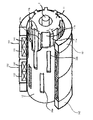
図6は、本発明の第2実施形態に係る電動パワーステアリング装置のトルクセンサを示す斜視図である。なお、同図において、上述した第1実施形態と同一の部材には同一の符号(番号)を付して、その説明を省略する。 FIG. 6 is a perspective view showing a torque sensor of the electric power steering apparatus according to the second embodiment of the present invention. In the figure, the same members as those in the first embodiment described above are denoted by the same reference numerals (numbers), and the description thereof is omitted.
この第2実施形態に係る電動パワーステアリング装置のトルクセンサでは、図6に示すように、円筒部材12の外周に該円筒部材12と同軸に配置された検出コイル131、141及び132、142の周囲、すなわち、検出コイル131、141を内包するヨーク151の軸方向外端及び検出コイル132、142を内包するヨーク152の軸方向外端に磁気シールド材161、162が配設されている。したがって、本実施形態に係る電動パワーステアリング装置によれば、検出コイル131、141及び132、142の4コイルからなるトルクセンサであっても、これらの4つの検出コイル131、141、132、142の磁気バランスを保つことができ、安定したトルク検出を実現することができる。
In the torque sensor of the electric power steering apparatus according to the second embodiment, as shown in FIG. 6, around the detection coils 131, 141 and 132, 142 arranged coaxially with the
以上、本発明の実施形態について具体的に説明してきたが、本発明はこれに限定されるものではなく、その趣旨を逸脱しない範囲で適宜変更可能である。 As mentioned above, although embodiment of this invention was described concretely, this invention is not limited to this, In the range which does not deviate from the meaning, it can change suitably.
1・・・入力軸
2・・・出力軸
3・・・トーションバー
4・・・ラック
5a,5b・・・ハウジング
7・・・ウォームホイール
8・・・ウォーム
11・・・センサシャフト部
12・・・円筒部材
12a,12b・・・窓
131,132,141,142・・・検出コイル
151,152・・・ヨーク
161,162・・・磁気シールド材
DESCRIPTION OF SYMBOLS 1 ... Input shaft 2 ...
Claims (2)
前記2対の検出コイルは、それぞれ2つの検出コイルで1つのヨークを共用するように該ヨークに内包されていることを特徴とする電動パワーステアリング装置。 AC signals are respectively applied to two bridge circuits including two pairs of detection coils whose impedances change in opposite directions according to the torque generated on the rotating shaft and resistors connected in series to the two pairs of detection coils. An electric power steering device comprising a torque sensor for applying and detecting the torque based on a differential signal of each bridge circuit;
The electric power steering apparatus, wherein the two pairs of detection coils are included in the yokes so that each of the two detection coils shares one yoke.
前記2対の検出コイルを内包するヨークの周囲には、磁気シールド材が配設されていることを特徴とする電動パワーステアリング装置。 AC signals are respectively applied to two bridge circuits including two pairs of detection coils whose impedances change in opposite directions according to the torque generated on the rotating shaft and resistors connected in series to the two pairs of detection coils. An electric power steering device comprising a torque sensor for applying and detecting the torque based on a differential signal of each bridge circuit;
An electric power steering apparatus characterized in that a magnetic shield material is disposed around a yoke containing the two pairs of detection coils.
Priority Applications (1)
| Application Number | Priority Date | Filing Date | Title |
|---|---|---|---|
| JP2010253229A JP5648435B2 (en) | 2010-11-11 | 2010-11-11 | Electric power steering apparatus and vehicle equipped with the same |
Applications Claiming Priority (1)
| Application Number | Priority Date | Filing Date | Title |
|---|---|---|---|
| JP2010253229A JP5648435B2 (en) | 2010-11-11 | 2010-11-11 | Electric power steering apparatus and vehicle equipped with the same |
Publications (2)
| Publication Number | Publication Date |
|---|---|
| JP2012103175A true JP2012103175A (en) | 2012-05-31 |
| JP5648435B2 JP5648435B2 (en) | 2015-01-07 |
Family
ID=46393742
Family Applications (1)
| Application Number | Title | Priority Date | Filing Date |
|---|---|---|---|
| JP2010253229A Expired - Fee Related JP5648435B2 (en) | 2010-11-11 | 2010-11-11 | Electric power steering apparatus and vehicle equipped with the same |
Country Status (1)
| Country | Link |
|---|---|
| JP (1) | JP5648435B2 (en) |
Cited By (1)
| Publication number | Priority date | Publication date | Assignee | Title |
|---|---|---|---|---|
| WO2014064856A1 (en) * | 2012-10-23 | 2014-05-01 | 日本精工株式会社 | Torque detection device, electric power steering device, and vehicle |
Citations (4)
| Publication number | Priority date | Publication date | Assignee | Title |
|---|---|---|---|---|
| JPH01170823A (en) * | 1987-12-26 | 1989-07-05 | Daido Steel Co Ltd | Torque sensor |
| JPH03238331A (en) * | 1990-02-16 | 1991-10-24 | Nissan Motor Co Ltd | Torque detecting apparatus |
| JP2002048656A (en) * | 2000-08-04 | 2002-02-15 | Nsk Ltd | Torque sensor control device |
| JP2006267045A (en) * | 2005-03-25 | 2006-10-05 | Nsk Ltd | Torque sensor |
-
2010
- 2010-11-11 JP JP2010253229A patent/JP5648435B2/en not_active Expired - Fee Related
Patent Citations (4)
| Publication number | Priority date | Publication date | Assignee | Title |
|---|---|---|---|---|
| JPH01170823A (en) * | 1987-12-26 | 1989-07-05 | Daido Steel Co Ltd | Torque sensor |
| JPH03238331A (en) * | 1990-02-16 | 1991-10-24 | Nissan Motor Co Ltd | Torque detecting apparatus |
| JP2002048656A (en) * | 2000-08-04 | 2002-02-15 | Nsk Ltd | Torque sensor control device |
| JP2006267045A (en) * | 2005-03-25 | 2006-10-05 | Nsk Ltd | Torque sensor |
Cited By (6)
| Publication number | Priority date | Publication date | Assignee | Title |
|---|---|---|---|---|
| WO2014064856A1 (en) * | 2012-10-23 | 2014-05-01 | 日本精工株式会社 | Torque detection device, electric power steering device, and vehicle |
| CN103930757A (en) * | 2012-10-23 | 2014-07-16 | 日本精工株式会社 | Torque detection device, electric power steering device, and vehicle |
| KR20150079670A (en) * | 2012-10-23 | 2015-07-08 | 닛본 세이고 가부시끼가이샤 | Torque detection device, electric power steering device, and vehicle |
| US9164010B2 (en) | 2012-10-23 | 2015-10-20 | Nsk Ltd. | Torque detection apparatus, electric power steering system and vehicle |
| JPWO2014064856A1 (en) * | 2012-10-23 | 2016-09-05 | 日本精工株式会社 | Torque detection device, electric power steering device, and vehicle |
| KR102008553B1 (en) | 2012-10-23 | 2019-08-07 | 닛본 세이고 가부시끼가이샤 | Torque detection apparatus, electric power steering system and vehicle |
Also Published As
| Publication number | Publication date |
|---|---|
| JP5648435B2 (en) | 2015-01-07 |
Similar Documents
| Publication | Publication Date | Title |
|---|---|---|
| JP2006267045A (en) | Torque sensor | |
| JP3584624B2 (en) | Torque sensor | |
| JP4026247B2 (en) | Torque sensor | |
| US6456090B1 (en) | Torque sensor | |
| EP2573523B1 (en) | Displacement Detecting Device, Vehicle Steering System, and Motor | |
| JPH08136366A (en) | Torque sensor | |
| JP2003065876A (en) | Abnormality detection device of torque sensor | |
| JP2010190674A (en) | Torque detection apparatus and electric power steering device | |
| JP5648435B2 (en) | Electric power steering apparatus and vehicle equipped with the same | |
| JP3664055B2 (en) | Torque sensor control device | |
| JP4573370B2 (en) | Torque sensor | |
| JP5018577B2 (en) | Electric power steering device | |
| EP3957961A1 (en) | Redundant sensor device and method for determining abnormality in redundant sensor device | |
| JP2012173009A (en) | Torque sensor and motor-driven power steering device with the same | |
| JP5668504B2 (en) | Torque sensor and electric power steering apparatus provided with the same | |
| JP2002013991A (en) | Device for detecting abnormality of torque sensor | |
| JP5807391B2 (en) | Torque sensor and electric power steering apparatus provided with the same | |
| JP5790142B2 (en) | Torque sensor and electric power steering apparatus provided with the same | |
| JP2010190704A (en) | Torque sensor and electric power steering device | |
| JP5821496B2 (en) | Torque sensor and electric power steering apparatus having the same | |
| JP3649057B2 (en) | Torque sensor | |
| JP3649069B2 (en) | Torque sensor | |
| JP2012237591A (en) | Torque sensor and electric power steering device equipped with the same | |
| JP2002022567A (en) | Abnormality detector for torque sensor | |
| JPH09329509A (en) | Torque sensor |
Legal Events
| Date | Code | Title | Description |
|---|---|---|---|
| A621 | Written request for application examination |
Free format text: JAPANESE INTERMEDIATE CODE: A621 Effective date: 20131001 |
|
| A977 | Report on retrieval |
Free format text: JAPANESE INTERMEDIATE CODE: A971007 Effective date: 20140122 |
|
| A131 | Notification of reasons for refusal |
Free format text: JAPANESE INTERMEDIATE CODE: A131 Effective date: 20140128 |
|
| A521 | Request for written amendment filed |
Free format text: JAPANESE INTERMEDIATE CODE: A523 Effective date: 20140326 |
|
| A131 | Notification of reasons for refusal |
Free format text: JAPANESE INTERMEDIATE CODE: A131 Effective date: 20140805 |
|
| A521 | Request for written amendment filed |
Free format text: JAPANESE INTERMEDIATE CODE: A523 Effective date: 20140916 |
|
| TRDD | Decision of grant or rejection written | ||
| A01 | Written decision to grant a patent or to grant a registration (utility model) |
Free format text: JAPANESE INTERMEDIATE CODE: A01 Effective date: 20141014 |
|
| A61 | First payment of annual fees (during grant procedure) |
Free format text: JAPANESE INTERMEDIATE CODE: A61 Effective date: 20141027 |
|
| R150 | Certificate of patent or registration of utility model |
Ref document number: 5648435 Country of ref document: JP Free format text: JAPANESE INTERMEDIATE CODE: R150 |
|
| LAPS | Cancellation because of no payment of annual fees |