JP2012102876A - Pressure regulating valve, in particular for activating clutch in automatic transmission for automobile - Google Patents
Pressure regulating valve, in particular for activating clutch in automatic transmission for automobile Download PDFInfo
- Publication number
- JP2012102876A JP2012102876A JP2011245756A JP2011245756A JP2012102876A JP 2012102876 A JP2012102876 A JP 2012102876A JP 2011245756 A JP2011245756 A JP 2011245756A JP 2011245756 A JP2011245756 A JP 2011245756A JP 2012102876 A JP2012102876 A JP 2012102876A
- Authority
- JP
- Japan
- Prior art keywords
- pressure control
- notch
- control valve
- valve body
- undercut
- Prior art date
- Legal status (The legal status is an assumption and is not a legal conclusion. Google has not performed a legal analysis and makes no representation as to the accuracy of the status listed.)
- Granted
Links
Images


Classifications
-
- F—MECHANICAL ENGINEERING; LIGHTING; HEATING; WEAPONS; BLASTING
- F16—ENGINEERING ELEMENTS AND UNITS; GENERAL MEASURES FOR PRODUCING AND MAINTAINING EFFECTIVE FUNCTIONING OF MACHINES OR INSTALLATIONS; THERMAL INSULATION IN GENERAL
- F16H—GEARING
- F16H61/00—Control functions within control units of change-speed- or reversing-gearings for conveying rotary motion ; Control of exclusively fluid gearing, friction gearing, gearings with endless flexible members or other particular types of gearing
- F16H61/04—Smoothing ratio shift
- F16H61/06—Smoothing ratio shift by controlling rate of change of fluid pressure
-
- F—MECHANICAL ENGINEERING; LIGHTING; HEATING; WEAPONS; BLASTING
- F16—ENGINEERING ELEMENTS AND UNITS; GENERAL MEASURES FOR PRODUCING AND MAINTAINING EFFECTIVE FUNCTIONING OF MACHINES OR INSTALLATIONS; THERMAL INSULATION IN GENERAL
- F16K—VALVES; TAPS; COCKS; ACTUATING-FLOATS; DEVICES FOR VENTING OR AERATING
- F16K31/00—Actuating devices; Operating means; Releasing devices
- F16K31/02—Actuating devices; Operating means; Releasing devices electric; magnetic
- F16K31/06—Actuating devices; Operating means; Releasing devices electric; magnetic using a magnet, e.g. diaphragm valves, cutting off by means of a liquid
- F16K31/0603—Multiple-way valves
- F16K31/061—Sliding valves
- F16K31/0613—Sliding valves with cylindrical slides
-
- F—MECHANICAL ENGINEERING; LIGHTING; HEATING; WEAPONS; BLASTING
- F16—ENGINEERING ELEMENTS AND UNITS; GENERAL MEASURES FOR PRODUCING AND MAINTAINING EFFECTIVE FUNCTIONING OF MACHINES OR INSTALLATIONS; THERMAL INSULATION IN GENERAL
- F16H—GEARING
- F16H61/00—Control functions within control units of change-speed- or reversing-gearings for conveying rotary motion ; Control of exclusively fluid gearing, friction gearing, gearings with endless flexible members or other particular types of gearing
-
- F—MECHANICAL ENGINEERING; LIGHTING; HEATING; WEAPONS; BLASTING
- F16—ENGINEERING ELEMENTS AND UNITS; GENERAL MEASURES FOR PRODUCING AND MAINTAINING EFFECTIVE FUNCTIONING OF MACHINES OR INSTALLATIONS; THERMAL INSULATION IN GENERAL
- F16K—VALVES; TAPS; COCKS; ACTUATING-FLOATS; DEVICES FOR VENTING OR AERATING
- F16K11/00—Multiple-way valves, e.g. mixing valves; Pipe fittings incorporating such valves
- F16K11/02—Multiple-way valves, e.g. mixing valves; Pipe fittings incorporating such valves with all movable sealing faces moving as one unit
- F16K11/06—Multiple-way valves, e.g. mixing valves; Pipe fittings incorporating such valves with all movable sealing faces moving as one unit comprising only sliding valves, i.e. sliding closure elements
- F16K11/065—Multiple-way valves, e.g. mixing valves; Pipe fittings incorporating such valves with all movable sealing faces moving as one unit comprising only sliding valves, i.e. sliding closure elements with linearly sliding closure members
- F16K11/07—Multiple-way valves, e.g. mixing valves; Pipe fittings incorporating such valves with all movable sealing faces moving as one unit comprising only sliding valves, i.e. sliding closure elements with linearly sliding closure members with cylindrical slides
- F16K11/0708—Multiple-way valves, e.g. mixing valves; Pipe fittings incorporating such valves with all movable sealing faces moving as one unit comprising only sliding valves, i.e. sliding closure elements with linearly sliding closure members with cylindrical slides comprising means to avoid jamming of the slide or means to modify the flow
-
- F—MECHANICAL ENGINEERING; LIGHTING; HEATING; WEAPONS; BLASTING
- F16—ENGINEERING ELEMENTS AND UNITS; GENERAL MEASURES FOR PRODUCING AND MAINTAINING EFFECTIVE FUNCTIONING OF MACHINES OR INSTALLATIONS; THERMAL INSULATION IN GENERAL
- F16H—GEARING
- F16H61/00—Control functions within control units of change-speed- or reversing-gearings for conveying rotary motion ; Control of exclusively fluid gearing, friction gearing, gearings with endless flexible members or other particular types of gearing
- F16H61/02—Control functions within control units of change-speed- or reversing-gearings for conveying rotary motion ; Control of exclusively fluid gearing, friction gearing, gearings with endless flexible members or other particular types of gearing characterised by the signals used
- F16H61/0202—Control functions within control units of change-speed- or reversing-gearings for conveying rotary motion ; Control of exclusively fluid gearing, friction gearing, gearings with endless flexible members or other particular types of gearing characterised by the signals used the signals being electric
- F16H61/0251—Elements specially adapted for electric control units, e.g. valves for converting electrical signals to fluid signals
Landscapes
- Engineering & Computer Science (AREA)
- General Engineering & Computer Science (AREA)
- Mechanical Engineering (AREA)
- Physics & Mathematics (AREA)
- Fluid Mechanics (AREA)
- Magnetically Actuated Valves (AREA)
- Control Of Transmission Device (AREA)
- Multiple-Way Valves (AREA)
Abstract
Description
本発明は、特に自動車用オートマチックトランスミッションに設けられたクラッチを制御するための圧力制御弁であって、ケーシングと、該ケーシング内でガイドされる摺動弁体とを備えており、該摺動弁体が、その周面に、摺動弁体の長手方向に延びる切欠きを有しており、該切欠きが、摺動弁体の第1の軸方向位置では、前記ケーシングに設けられた2つの横方向孔を互いに流体接続し、且つ第2の軸方向位置では互いに分離する形式のものに関する。 In particular, the present invention is a pressure control valve for controlling a clutch provided in an automatic transmission for an automobile, and includes a casing and a sliding valve body guided in the casing, and the sliding valve The body has a notch extending in the longitudinal direction of the sliding valve body on its peripheral surface, and the notch is provided in the casing 2 at the first axial position of the sliding valve body. It relates to a type in which two lateral holes are fluidly connected to each other and separated from each other in a second axial position.
自動車のオートマチックトランスミッションに設けられたクラッチを制御するための複数の圧力制御器が市場から公知である。これらの圧力制御器は電磁石を介して操作され、この電磁石は、スライド弁の軸方向に摺動可能なピストンを、少なくとも2つの終端位置又は切換位置にもたらすことができる。電磁石の給電時に、前記ピストンが軸方向に摺動され、その結果、ピストンの制御縁部がスライド弁の1開口を開放することができるようになっており、これにより、例えば流体流がクラッチの所定の作動部材に流入することができる。 A plurality of pressure controllers for controlling a clutch provided in an automatic transmission of an automobile is known from the market. These pressure controllers are operated via electromagnets, which can bring pistons slidable in the axial direction of the slide valve into at least two end positions or switching positions. When the electromagnet is fed, the piston is slid in the axial direction, so that the control edge of the piston can open one opening of the slide valve so that, for example, the fluid flow is It can flow into a predetermined actuating member.
前記開口を通流する流体流は、付加的に軸方向の力成分を生ぜしめ、この軸方向の力成分が大きければ大きいほど、所望の半径方向からの、流体流の方向の偏向が著しくなる。軸方向の力成分は、電磁石の力に抗して作用し且つ前記開口を通流する流体流を減少させる。このことは、今日のオートマチックトランスミッションに課せられた、比較的多くの通流量及び短い切換時間に関する要求を妨げている。 The fluid flow through the opening additionally generates an axial force component, the greater the axial force component, the more the deflection of the fluid flow direction from the desired radial direction. . The axial force component acts against the force of the electromagnet and reduces the fluid flow through the opening. This hinders the demands on today's automatic transmissions for relatively high flow rates and short switching times.
この専門分野における特許公開は、例えばEP1703178A2において成されている。 Patent publication in this specialized field is made, for example, in EP 1703178 A2.
本発明の課題は、上記公知の欠点を回避することにある。 The object of the present invention is to avoid the above known drawbacks.
この課題を解決するために本発明では、切欠きが、少なくとも1つの横方向孔、特に流体流出部として働く横方向孔の直近に位置する端部に、アンダカットを備えた端面を有しているようにした。 In order to solve this problem, in the present invention, the notch has an end face provided with an undercut at an end portion located in the immediate vicinity of at least one lateral hole, particularly a lateral hole serving as a fluid outflow portion. I tried to be.
有利な構成は従属請求項に記載されている。更に、本発明に関して重要な構成は、以下の説明及び図面に記載されており、これらの構成は、再度明確に述べるまでもなく、単独でも様々な組み合わせでも、本発明にとって重要であってよい。 Advantageous configurations are set forth in the dependent claims. Furthermore, important features relating to the present invention are set forth in the following description and drawings, and these features may be important to the present invention, either alone or in various combinations, without needing to be clearly stated again.
本発明による手段は、圧力制御弁の作動時に生じる流体流に起因する軸方向の力成分が比較的小さく、且つ圧力制御弁の通流量及び/又は切換速度が比較的大きいという利点を有している。同時に、本発明による圧力制御弁は、特に頑丈に作動する。それというのも、圧力制御弁のケーシングが横方向孔の形の半径方向の開口しか有しておらず、環状溝又は周方向の制御縁部を必ずしも有してはいないからである。 The means according to the invention have the advantage that the axial force component due to the fluid flow generated during operation of the pressure control valve is relatively small and the flow rate and / or switching speed of the pressure control valve is relatively large. Yes. At the same time, the pressure control valve according to the invention operates particularly robustly. This is because the casing of the pressure control valve only has a radial opening in the form of a transverse hole and does not necessarily have an annular groove or a circumferential control edge.
本発明による圧力制御弁は、少なくとも2つの液圧接続部を有しており、これらの液圧接続部はそれぞれ、圧力制御弁の(大抵は円筒形の)ケーシングに設けられた横方向孔として構成されている。これらの「横方向孔」は、円形の横方向孔として構成されているか、又は択一的に円形とは異なる横断面を備えて構成されていてよいと理解される。例えば、横方向孔は、楕円形又は方形の横断面を備えた通路として構成されていてもよい。圧力制御弁内に配置された摺動弁体の軸方向に延在する1切欠きを介して、前記液圧接続部は、摺動弁体の所定の軸方向位置に関連して互いに流体接続され且つ/又は互いに流体分離され得る。圧力制御弁内に生じる、部分的に軸方向の流体流は、本発明に基づき、少なくとも一時的に流体流出部として働く第2の横方向孔に向かって半径方向に変向され、この場合、摺動弁体の周面の、前記第2の横方向孔の直近に位置する端部において、一方の端面がアンダカットを有している。これにより、摺動弁体の前記端面に沿って、軸方向から半径方向に変向された流体流には、軸方向の力成分が減少されるという影響が及ぼされる。なぜならば、横方向孔の領域の圧力制御弁のケーシングは、環状溝を有していないので、摺動弁体の所要の軸方向行程が比較的大きくてよく、これにより、圧力制御弁の切換え動作は特に強力になる。別の利点は、摺動弁体とケーシングとの間のギャップにおける漏れが比較的少ない、ということにより得られる。 The pressure control valve according to the invention has at least two hydraulic connections, each of which is a lateral hole provided in the (mostly cylindrical) casing of the pressure control valve. It is configured. It is understood that these “lateral holes” may be configured as circular lateral holes, or alternatively may be configured with a cross-section that differs from a circular shape. For example, the transverse hole may be configured as a passage with an elliptical or square cross section. Via one notch extending in the axial direction of the sliding valve body arranged in the pressure control valve, the hydraulic connection part is fluidly connected to each other in relation to a predetermined axial position of the sliding valve body. And / or may be fluidly separated from each other. In accordance with the present invention, the partially axial fluid flow that occurs in the pressure control valve is diverted radially toward a second lateral hole that at least temporarily serves as a fluid outlet, in this case, One end surface has an undercut at the end portion of the peripheral surface of the sliding valve body located in the immediate vicinity of the second lateral hole. Accordingly, the force component in the axial direction is reduced in the fluid flow that is changed from the axial direction to the radial direction along the end face of the sliding valve body. Because the casing of the pressure control valve in the region of the lateral hole does not have an annular groove, the required axial stroke of the sliding valve body may be relatively large, thereby switching the pressure control valve The operation is particularly powerful. Another advantage is obtained by the fact that there is relatively little leakage in the gap between the sliding valve body and the casing.
当該圧力弁は、摺動弁体の半径方向軸線に関してアンダカットの角度が約15°〜45°、特に有利には約30°であると、特に良好に作動する。これにより、多くの圧力制御弁に関して、摺動弁体若しくはアンダカットの、流れ案内に特に適したジオメトリが得られる。 The pressure valve works particularly well when the undercut angle with respect to the radial axis of the sliding valve body is about 15 ° to 45 °, particularly preferably about 30 °. This provides a geometry that is particularly suitable for flow guidance, for sliding valves or undercuts, for many pressure control valves.
圧力制御弁の1構成では、切欠きの軸方向に延在する基部から、アンダカットされた端面に至る移行部に、丸みが付けられている。例えば、所定の曲率を有する約0.03mmの半径部がアンダカットの30°の角度との関係において特に適した構成であってよく、この構成は、圧力制御弁の製作性に関して良好な妥協点を成していてもよい。 In one configuration of the pressure control valve, a transition portion extending from the base portion extending in the axial direction of the notch to the undercut end face is rounded. For example, a radius of about 0.03 mm with a predetermined curvature may be a particularly suitable configuration in relation to the angle of 30 ° of the undercut, which configuration is a good compromise with respect to manufacturability of the pressure control valve. May be included.
更に、前記切欠きは、摺動弁体の全周にわたって環状溝の形式で延在している。これにより、摺動弁体は切欠きの領域に最大の軸方向横断面を有しているので、圧力制御弁の切換え動作が改善される。別の利点は、摺動弁体の角度配向が不要であることによって得られる。 Furthermore, the notch extends in the form of an annular groove over the entire circumference of the sliding valve body. Thereby, since the sliding valve body has the largest axial cross section in the region of the notch, the switching operation of the pressure control valve is improved. Another advantage is obtained by not requiring the angular orientation of the sliding valve body.
以下に、本発明を実施するための最良の形態を図面につき詳しく説明する。全ての図面において、同じ機能を有するエレメント及び量には、異なる実施形態においても同一符号が用いられる。 In the following, the best mode for carrying out the present invention will be described in detail with reference to the drawings. In all the drawings, elements and quantities having the same function are denoted by the same reference numerals in different embodiments.
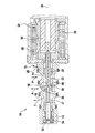
図1には、自動車用オートマチックトランスミッションに設けられるクラッチを制御するための圧力制御弁10が、軸方向で断面されて示されている。圧力制御弁10は、横方向孔14として構成された第1の横方向開口と、横方向孔16として構成された第2の横方向開口と、別の横方向孔18,20とを備えた円筒形のケーシング12を有しており、第1の横方向開口と第2の横方向開口とは、長手方向軸線26の方向で見て互いに隔てられている(「軸方向の間隔」)。ケーシング12内には、このケーシング12に対して同軸的な摺動弁体22が配置されている。この摺動弁体22は、電磁石24によって長手方向軸線26の方向で軸方向に摺動され得る。ピストン状に構成された摺動弁体22は、本実施形態では長手方向軸線26の方向に延びる(「軸方向の延在」)3つの切欠き23を有しており、これらの切欠き23は、それぞれ摺動弁体22の全周にわたって環状溝状に延びている。図面中央の切欠き23だけに符号が付されている。電磁石24は、コイル28と、磁極29と、摺動弁体22に作用する可動子30とを有している。図面左側の領域において、摺動弁体22の一方の端区分と、ケーシング12内に配置された収容部32との間には、コイルばね34が配置されている。図1に描かれた円36は、摺動弁体22のアンダカット40を備えた端面38を示すものである。更に、圧力制御に必要な通路41が示されている。圧力制御弁10は、長手方向軸線26を中心としてほぼ回転対称的に構成されている。
FIG. 1 shows a cross section in the axial direction of a
図1に示した摺動弁体22は中間の軸方向位置を占めており、この中間の軸方向位置では作動接続部Aが、流出接続部Tからも、流入接続部Pからも分離されている。「第1の」軸方向位置(図1には図示せず)では、コイル28が給電されており、摺動弁体22は図面左側の位置に位置しており、この場合、作動接続部A若しくは第2の横方向孔16は、流入接続部P若しくは第1の横方向孔14に液圧的に接続されている。「第2の」軸方向位置(やはり図1には図示せず)では、コイル28は給電されておらず、摺動弁体22は図面右側の位置に位置しており、この場合、作動接続部A若しくは第2の横方向孔16は、流出接続部T若しくは横方向孔18に液圧的に接続されている。この第2の軸方向位置では、横方向孔14は横方向孔16から流体的に分離されている。
The sliding
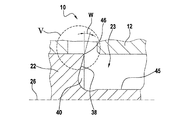
図2には、図1に関してやや拡大された摺動弁体22の軸方向断面図が示されている。本実施形態では、制御縁部42と、可動子側の端区分44とが、長手方向軸線26に関して約10°の面取り部若しくは傾斜部を有している。中央の切欠き23は、軸方向に延びる基部45を有している。端面38の半径方向外側の縁部は制御縁部46を形成している。
FIG. 2 shows an axial sectional view of the sliding
図3には、図2に符号IIIで示した部分の詳細図が示されている。端面38のアンダカット40は、摺動弁体22の半径方向軸線に関して30°の角度Wで構成されている。更に、アンダカット40は端面38と基部45との間に、所定の曲率を有する第1の半径部R1を有しており、且つ制御縁部46に所定の曲率を有する第2の半径部R2を備えた丸みを有している。つまり、切欠き23の、軸方向に延びる基部45からアンダカットされた端面38への移行部は、やや丸みを付けられている。本実施形態では、基部45に対するアンダカット40の減寸は約0.05mmであるか、又は0.05mm未満である。
FIG. 3 shows a detailed view of the portion indicated by reference numeral III in FIG. The undercut 40 of the
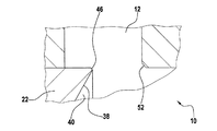
図4には、摺動弁体22の円36の領域(図1参照)における軸方向区分の第1の概略断面図が示されている。図5には、図4に符号Vで示した部分の詳細図が示されている。本実施形態では、アンダカット40の角度Wは約15°である。更に指摘しておくと、制御縁部46及び面取り部52の領域の傾斜は45°である。
FIG. 4 shows a first schematic cross-sectional view of the axial section in the region of the
図6には、図4と同様の第2の概略断面図が示されている。図7にもやはり、図6に符号VIIで示した部分の詳細図が示されている。本実施形態では、角度Wは約30°であるが、45°であってもよい。 FIG. 6 shows a second schematic cross-sectional view similar to FIG. FIG. 7 also shows a detailed view of the portion indicated by reference numeral VII in FIG. In this embodiment, the angle W is about 30 °, but it may be 45 °.
電磁石24若しくはコイル28が給電されると、可動子30は磁力によって図1では左側に向かって軸方向に摺動され、その結果、横方向孔14,16は互いに流体接続されている。圧力制限弁10において中央の切欠き23には、流入接続部Pから作動接続部Aに流れる、ほぼ水平方向の流体流が形成される。この流体流は、円36の領域内で横方向孔16に向かって半径方向外側に変向される。
When the
10 圧力制御弁、 12 ケーシング、 14 第1の横方向孔、 16 第2の横方向孔、 18,20 別の横方向孔、 22 摺動弁体、 23 切欠き、 24 電磁石、 26 長手方向軸線、 28 コイル、 29 磁極、 30 可動子、 32 収容部、 34 コイルばね、 36 円、 38 端面、 40 アンダカット、 41 通路、 42 制御縁部、 44 端区分、 45 基部、 46 制御縁部、 48 減寸、 52 面取り部、 A 作動接続部、 T 流出接続部、 P 流入接続部、 R1 第1の半径部、 R2 第2の半径部、 W アンダカットの角度
DESCRIPTION OF
Claims (4)
切欠き(23)が、少なくとも1つの横方向孔(16)、特に流体流出部として働く横方向孔の直近に位置する端部に、アンダカット(40)を備えた端面(38)を有していることを特徴とする、圧力制御弁。 In particular, a pressure control valve (10) for controlling a clutch provided in an automatic transmission for an automobile, comprising a casing (12) and a sliding valve element (22) guided in the casing (12). The slide valve body (22) has a notch (23) extending in the longitudinal direction of the slide valve body on the peripheral surface thereof, and the notch (23) is a slide valve. In the first axial position of the body (22), the two lateral holes (14, 16) provided in the casing are fluidly connected to each other and separated from each other in the second axial position. ,
The notch (23) has an end face (38) with an undercut (40) at the end located in the immediate vicinity of the at least one lateral hole (16), in particular the lateral hole serving as a fluid outlet. A pressure control valve characterized by comprising:
Applications Claiming Priority (2)
| Application Number | Priority Date | Filing Date | Title |
|---|---|---|---|
| DE102010043697.6 | 2010-11-10 | ||
| DE102010043697A DE102010043697A1 (en) | 2010-11-10 | 2010-11-10 | Pressure control valve, in particular for controlling a clutch in a motor vehicle automatic transmission |
Publications (2)
| Publication Number | Publication Date |
|---|---|
| JP2012102876A true JP2012102876A (en) | 2012-05-31 |
| JP5911269B2 JP5911269B2 (en) | 2016-04-27 |
Family
ID=45970957
Family Applications (1)
| Application Number | Title | Priority Date | Filing Date |
|---|---|---|---|
| JP2011245756A Expired - Fee Related JP5911269B2 (en) | 2010-11-10 | 2011-11-09 | Especially a pressure control valve for controlling the clutch of an automotive automatic transmission |
Country Status (5)
| Country | Link |
|---|---|
| US (1) | US20120112111A1 (en) |
| JP (1) | JP5911269B2 (en) |
| KR (1) | KR20120050384A (en) |
| CN (1) | CN102537416B (en) |
| DE (1) | DE102010043697A1 (en) |
Families Citing this family (4)
| Publication number | Priority date | Publication date | Assignee | Title |
|---|---|---|---|---|
| ES2682274T3 (en) * | 2012-07-11 | 2018-09-19 | Flextronics Ap, Llc | Direct Acting Solenoid Actuator |
| CN103851211B (en) * | 2012-11-30 | 2017-05-17 | 上海航天控制工程研究所 | Pressure proportional electromagnetic valve slide valve level structure with adjustable gain |
| DE102012224019A1 (en) | 2012-12-20 | 2014-06-26 | Robert Bosch Gmbh | Slide valve for controlling automatic transmission for motor car, has valve spool whose first and second apertures are hydraulically connected over recesses of collar and housing, in a pressure drop position |
| DE102016120118A1 (en) * | 2016-10-21 | 2018-04-26 | Hilite Germany Gmbh | Electromagnetic pressure control valve |
Citations (2)
| Publication number | Priority date | Publication date | Assignee | Title |
|---|---|---|---|---|
| JP2006258293A (en) * | 2005-03-17 | 2006-09-28 | Borgwarner Inc | Automatic transmission having pressure regulator for performing compensation of flowing force |
| WO2010112263A2 (en) * | 2009-03-31 | 2010-10-07 | Robert Bosch Gmbh | Pressure control valve, particularly for an automatic transmission in a motor vehicle |
Family Cites Families (14)
| Publication number | Priority date | Publication date | Assignee | Title |
|---|---|---|---|---|
| US3123335A (en) * | 1964-03-03 | Stabilized piston valve | ||
| US2747612A (en) * | 1951-04-24 | 1956-05-29 | Research Corp | Force-compensated flow valve |
| US2812775A (en) * | 1956-09-10 | 1957-11-12 | New York Air Brake Co | Stabilizing means for high pressure hydraulic valves of the plunger type |
| US2971536A (en) * | 1958-06-26 | 1961-02-14 | Caterpillar Tractor Co | Hydraulic control valve throttling mechanism |
| US3243025A (en) * | 1964-03-12 | 1966-03-29 | Minneapolis Moline Inc | Control valve for hydraulically actuated clutches |
| DE3109116A1 (en) * | 1981-03-11 | 1982-11-04 | Elektro-Mechanik Gmbh, 5963 Wenden | CONTINUOUS VALVE WITH ROTARY VALVE OR LENGTH VALVE |
| US4667930A (en) * | 1986-06-09 | 1987-05-26 | Caterpillar Inc. | Metering slot configuration for a valve spool |
| GB8717963D0 (en) * | 1987-07-29 | 1987-09-03 | Vickers Systems Ltd | Spool |
| US4941508A (en) * | 1989-12-28 | 1990-07-17 | Dana Corporation | Force balanced hydraulic spool valve |
| DE4131830C3 (en) * | 1991-09-20 | 2000-03-23 | Mannesmann Ag | Tappet for slide valves |
| US6349920B1 (en) * | 1998-07-24 | 2002-02-26 | Caterpillar Inc. | Poppet valve shaping for quick valve opening |
| JP3717158B2 (en) * | 2001-11-09 | 2005-11-16 | 本田技研工業株式会社 | Hydraulic valve |
| US8464756B2 (en) * | 2009-09-22 | 2013-06-18 | Eaton Corporation | Spool valve |
| CN201526549U (en) * | 2009-10-16 | 2010-07-14 | 中国航天科技集团公司第六研究院第十一研究所 | Inverse-proportion pressure reducing valve |
-
2010
- 2010-11-10 DE DE102010043697A patent/DE102010043697A1/en not_active Ceased
-
2011
- 2011-11-04 US US13/289,704 patent/US20120112111A1/en not_active Abandoned
- 2011-11-09 CN CN201110462083.2A patent/CN102537416B/en active Active
- 2011-11-09 KR KR1020110116262A patent/KR20120050384A/en not_active Application Discontinuation
- 2011-11-09 JP JP2011245756A patent/JP5911269B2/en not_active Expired - Fee Related
Patent Citations (2)
| Publication number | Priority date | Publication date | Assignee | Title |
|---|---|---|---|---|
| JP2006258293A (en) * | 2005-03-17 | 2006-09-28 | Borgwarner Inc | Automatic transmission having pressure regulator for performing compensation of flowing force |
| WO2010112263A2 (en) * | 2009-03-31 | 2010-10-07 | Robert Bosch Gmbh | Pressure control valve, particularly for an automatic transmission in a motor vehicle |
Also Published As
| Publication number | Publication date |
|---|---|
| US20120112111A1 (en) | 2012-05-10 |
| CN102537416A (en) | 2012-07-04 |
| CN102537416B (en) | 2017-10-27 |
| KR20120050384A (en) | 2012-05-18 |
| JP5911269B2 (en) | 2016-04-27 |
| DE102010043697A1 (en) | 2012-05-10 |
Similar Documents
| Publication | Publication Date | Title |
|---|---|---|
| US9027598B2 (en) | Steplessly adjustable hydraulic insert valve | |
| JP6756622B2 (en) | Capacity control valve | |
| JP5615286B2 (en) | Solenoid valve | |
| KR101546979B1 (en) | Valve part for a control valve for control of pressure medium flows | |
| KR101638892B1 (en) | A control valve | |
| JP2014152885A (en) | Pilot-driven solenoid valve of piston structure | |
| US9732748B2 (en) | Valve unit and a fluid working machine comprising a valve unit | |
| EP3098493B1 (en) | Solenoid valve | |
| JP2015533409A (en) | Valve cage with no dead band between the noise reduction section and the high volume flow section | |
| JP5911269B2 (en) | Especially a pressure control valve for controlling the clutch of an automotive automatic transmission | |
| JP2014214872A (en) | Central valve for rotary actuator | |
| CN110036226B (en) | Electromagnetic valve | |
| CN201763711U (en) | Hydraulic proportional control valve | |
| US8413950B2 (en) | Actuating solenoid and non-stick disk | |
| JP4260697B2 (en) | solenoid valve | |
| JP6647540B2 (en) | Regulating unit for a mechanically adjustable coolant pump of an internal combustion engine | |
| CN107109973A (en) | Central valve for a camshaft adjusting device | |
| JP4093092B2 (en) | solenoid valve | |
| KR20150077297A (en) | On-off valve | |
| JP2007100829A (en) | Valve device | |
| EP4296552A1 (en) | Solenoid valve | |
| JP2012255508A (en) | Fluid control valve | |
| CN111503315B (en) | Quick switch valve | |
| JP6462633B2 (en) | Solenoid valve and oil pump | |
| JP5773077B2 (en) | solenoid valve |
Legal Events
| Date | Code | Title | Description |
|---|---|---|---|
| A621 | Written request for application examination |
Free format text: JAPANESE INTERMEDIATE CODE: A621 Effective date: 20141105 |
|
| A977 | Report on retrieval |
Free format text: JAPANESE INTERMEDIATE CODE: A971007 Effective date: 20150723 |
|
| A131 | Notification of reasons for refusal |
Free format text: JAPANESE INTERMEDIATE CODE: A131 Effective date: 20150727 |
|
| A521 | Request for written amendment filed |
Free format text: JAPANESE INTERMEDIATE CODE: A523 Effective date: 20151020 |
|
| TRDD | Decision of grant or rejection written | ||
| A01 | Written decision to grant a patent or to grant a registration (utility model) |
Free format text: JAPANESE INTERMEDIATE CODE: A01 Effective date: 20160229 |
|
| A61 | First payment of annual fees (during grant procedure) |
Free format text: JAPANESE INTERMEDIATE CODE: A61 Effective date: 20160329 |
|
| R150 | Certificate of patent or registration of utility model |
Ref document number: 5911269 Country of ref document: JP Free format text: JAPANESE INTERMEDIATE CODE: R150 |
|
| LAPS | Cancellation because of no payment of annual fees |