JP2012102811A - Sealing device and linear guide device - Google Patents
Sealing device and linear guide device Download PDFInfo
- Publication number
- JP2012102811A JP2012102811A JP2010252222A JP2010252222A JP2012102811A JP 2012102811 A JP2012102811 A JP 2012102811A JP 2010252222 A JP2010252222 A JP 2010252222A JP 2010252222 A JP2010252222 A JP 2010252222A JP 2012102811 A JP2012102811 A JP 2012102811A
- Authority
- JP
- Japan
- Prior art keywords
- guide rail
- slider
- sealing device
- end seal
- seal
- Prior art date
- Legal status (The legal status is an assumption and is not a legal conclusion. Google has not performed a legal analysis and makes no representation as to the accuracy of the status listed.)
- Granted
Links
Images


Classifications
-
- F—MECHANICAL ENGINEERING; LIGHTING; HEATING; WEAPONS; BLASTING
- F16—ENGINEERING ELEMENTS AND UNITS; GENERAL MEASURES FOR PRODUCING AND MAINTAINING EFFECTIVE FUNCTIONING OF MACHINES OR INSTALLATIONS; THERMAL INSULATION IN GENERAL
- F16C—SHAFTS; FLEXIBLE SHAFTS; ELEMENTS OR CRANKSHAFT MECHANISMS; ROTARY BODIES OTHER THAN GEARING ELEMENTS; BEARINGS
- F16C43/00—Assembling bearings
- F16C43/04—Assembling rolling-contact bearings
- F16C43/045—Mounting or replacing seals
-
- F—MECHANICAL ENGINEERING; LIGHTING; HEATING; WEAPONS; BLASTING
- F16—ENGINEERING ELEMENTS AND UNITS; GENERAL MEASURES FOR PRODUCING AND MAINTAINING EFFECTIVE FUNCTIONING OF MACHINES OR INSTALLATIONS; THERMAL INSULATION IN GENERAL
- F16C—SHAFTS; FLEXIBLE SHAFTS; ELEMENTS OR CRANKSHAFT MECHANISMS; ROTARY BODIES OTHER THAN GEARING ELEMENTS; BEARINGS
- F16C29/00—Bearings for parts moving only linearly
- F16C29/04—Ball or roller bearings
- F16C29/06—Ball or roller bearings in which the rolling bodies circulate partly without carrying load
- F16C29/0633—Ball or roller bearings in which the rolling bodies circulate partly without carrying load with a bearing body defining a U-shaped carriage, i.e. surrounding a guide rail or track on three sides
- F16C29/0635—Ball or roller bearings in which the rolling bodies circulate partly without carrying load with a bearing body defining a U-shaped carriage, i.e. surrounding a guide rail or track on three sides whereby the return paths are provided as bores in a main body of the U-shaped carriage, e.g. the main body of the U-shaped carriage is a single part with end caps provided at each end
- F16C29/0638—Ball or roller bearings in which the rolling bodies circulate partly without carrying load with a bearing body defining a U-shaped carriage, i.e. surrounding a guide rail or track on three sides whereby the return paths are provided as bores in a main body of the U-shaped carriage, e.g. the main body of the U-shaped carriage is a single part with end caps provided at each end with balls
- F16C29/0642—Ball or roller bearings in which the rolling bodies circulate partly without carrying load with a bearing body defining a U-shaped carriage, i.e. surrounding a guide rail or track on three sides whereby the return paths are provided as bores in a main body of the U-shaped carriage, e.g. the main body of the U-shaped carriage is a single part with end caps provided at each end with balls with four rows of balls
- F16C29/0647—Ball or roller bearings in which the rolling bodies circulate partly without carrying load with a bearing body defining a U-shaped carriage, i.e. surrounding a guide rail or track on three sides whereby the return paths are provided as bores in a main body of the U-shaped carriage, e.g. the main body of the U-shaped carriage is a single part with end caps provided at each end with balls with four rows of balls with load directions in X-arrangement
-
- F—MECHANICAL ENGINEERING; LIGHTING; HEATING; WEAPONS; BLASTING
- F16—ENGINEERING ELEMENTS AND UNITS; GENERAL MEASURES FOR PRODUCING AND MAINTAINING EFFECTIVE FUNCTIONING OF MACHINES OR INSTALLATIONS; THERMAL INSULATION IN GENERAL
- F16C—SHAFTS; FLEXIBLE SHAFTS; ELEMENTS OR CRANKSHAFT MECHANISMS; ROTARY BODIES OTHER THAN GEARING ELEMENTS; BEARINGS
- F16C29/00—Bearings for parts moving only linearly
- F16C29/08—Arrangements for covering or protecting the ways
- F16C29/084—Arrangements for covering or protecting the ways fixed to the carriage or bearing body movable along the guide rail or track
- F16C29/086—Seals being essentially U-shaped, e.g. for a U-shaped carriage
-
- F—MECHANICAL ENGINEERING; LIGHTING; HEATING; WEAPONS; BLASTING
- F16—ENGINEERING ELEMENTS AND UNITS; GENERAL MEASURES FOR PRODUCING AND MAINTAINING EFFECTIVE FUNCTIONING OF MACHINES OR INSTALLATIONS; THERMAL INSULATION IN GENERAL
- F16C—SHAFTS; FLEXIBLE SHAFTS; ELEMENTS OR CRANKSHAFT MECHANISMS; ROTARY BODIES OTHER THAN GEARING ELEMENTS; BEARINGS
- F16C33/00—Parts of bearings; Special methods for making bearings or parts thereof
- F16C33/72—Sealings
- F16C33/76—Sealings of ball or roller bearings
-
- F—MECHANICAL ENGINEERING; LIGHTING; HEATING; WEAPONS; BLASTING
- F16—ENGINEERING ELEMENTS AND UNITS; GENERAL MEASURES FOR PRODUCING AND MAINTAINING EFFECTIVE FUNCTIONING OF MACHINES OR INSTALLATIONS; THERMAL INSULATION IN GENERAL
- F16C—SHAFTS; FLEXIBLE SHAFTS; ELEMENTS OR CRANKSHAFT MECHANISMS; ROTARY BODIES OTHER THAN GEARING ELEMENTS; BEARINGS
- F16C41/00—Other accessories, e.g. devices integrated in the bearing not relating to the bearing function as such
- F16C41/008—Identification means, e.g. markings, RFID-tags; Data transfer means
Landscapes
- Engineering & Computer Science (AREA)
- General Engineering & Computer Science (AREA)
- Mechanical Engineering (AREA)
- Bearings For Parts Moving Linearly (AREA)
- Sealing Of Bearings (AREA)
Abstract
Description
本発明は、シール装置及びそれを備えたリニアガイド装置に関する。 The present invention relates to a seal device and a linear guide device including the seal device.
従来から、工作機械等で使用されているリニアガイド装置は、軸方向に延びる転動体転動溝を外面に有する案内レールと、案内レールの転動体転動溝に対向して形成された転動体転動溝を有し、案内レールに相対移動可能に跨架されるスライダとを備えている。
スライダは、スライダ本体と、スライダ本体の移動方向両端面に接合されたエンドキャップとを備えており、エンドキャップのスライダ本体と反対側の面には、エンドシールが取り付けられている。案内レールとスライダとの間に形成される空隙部にごみ、粉塵、切粉、切屑等の異物が入り込み、転動体転動溝に付着すると、転動体の円滑な転動が妨げられることから、このエンドシールは、前記空隙部への異物の侵入を防ぐために、前記空隙部の開口部分をシールしている。これにより、リニアガイド装置の良好な作動性が保持されている。また、エンドシールは、スライダ内部で発生した粉塵をスライダの外部へ排出するのを抑制する役割も果たしている。
Conventionally, a linear guide device used in a machine tool or the like includes a guide rail having a rolling element rolling groove extending in the axial direction on the outer surface, and a rolling element formed to face the rolling element rolling groove of the guide rail. A slider having a rolling groove and straddling the guide rail so as to be relatively movable.
The slider includes a slider body and end caps joined to both end surfaces of the slider body in the moving direction, and an end seal is attached to the surface of the end cap opposite to the slider body. Since foreign matter such as dust, dust, chips and chips enters the gap formed between the guide rail and the slider and adheres to the rolling element rolling groove, smooth rolling of the rolling element is hindered. The end seal seals the opening of the gap in order to prevent foreign matter from entering the gap. Thereby, the favorable operability of the linear guide device is maintained. Further, the end seal also plays a role of suppressing discharge of dust generated inside the slider to the outside of the slider.
したがって、前記空隙部への異物の侵入を的確に防ぐために、案内レールの外面とこれに対向するエンドシールの対向面との隙間が所定の間隔になるように、案内レールの外面に対するエンドシールの位置を決めてエンドシールをスライダに装着することが必要となる。
案内レールの外面に対するエンドシールの位置を決めてエンドシールをスライダに装着する構成のリニアガイド装置としては、例えば、特許文献1及び2に記載されているリニアガイド装置がある。
Therefore, in order to prevent foreign matter from entering the gap, the gap between the outer surface of the guide rail and the opposite surface of the end seal that faces the gap is a predetermined distance. It is necessary to determine the position and attach the end seal to the slider.
As a linear guide device configured to determine the position of the end seal with respect to the outer surface of the guide rail and attach the end seal to the slider, for example, there are linear guide devices described in
しかしながら、特許文献1に記載されているリニアガイド装置は、スライダに連結される部品に突起を設け、それによりエンドシールの位置の固定を行うものである。したがって、スライダと連結される部品の取り付け位置のずれや、突起自体の位置がずれる可能性があるため、そのずれがエンドシールの位置決めに影響を及ぼし、エンドシールの位置決めの精度が悪化する恐れがある。
However, the linear guide device described in
また、特許文献2に記載されているリニアガイド装置は、エンドシールのシール部が案内レールと接触しているため、エンドシール自体が案内レールに沿って位置決めされてしまう。さらに、案内レールと接触するタイプのエンドシールを備えるリニアガイド装置は、エンドシールを取り付けることでスライダの移動における摺動抵抗が増加する恐れがある。また、低発塵を要求される使用環境においては、接触タイプのシールが摺動することで発塵してしまい、低発塵化を実現できなくなる恐れがある。
In the linear guide device described in
摺動抵抗の増加と発塵化の問題は、案内レールと非接触となるエンドシールを使用することで解決することができる。案内レールと非接触のタイプのエンドシールを取り付ける場合は、案内レールとエンドシールの間に規定の厚さのシムを挟みつつエンドシールをスライダに取り付けることにより、案内レールの外面とエンドシールの対向面との間の隙間が規定値となるように管理することができる。 The problem of increased sliding resistance and dust generation can be solved by using an end seal that is not in contact with the guide rail. When installing an end seal that is not in contact with the guide rail, attach the end seal to the slider while sandwiching a shim with a specified thickness between the guide rail and the end seal, so that the outer surface of the guide rail faces the end seal. It can be managed so that the gap between the surfaces becomes a specified value.
しかし、エンドシールを取り付ける際に、毎回シムを使用するのは作業に手間がかかるため好ましくない。また、案内レールとエンドシールとの間の隙間が極僅かな場合に、金属製のエンドシールを取り付ける場合には、エンドシールが案内レールの予期せぬ箇所に接触してしまい、案内レールに傷がつく恐れがあった。
本発明は、このような問題を解決するためになされたものであり、位置決め専用の冶具を用いることなく、高精度に位置決めしつつ取り付けることができる非接触型のシール装置、及び、該シール装置を備える、低発塵で、かつ、良好な作動性を保持したリニアガイド装置を提供することを目的とする。
However, it is not preferable to use a shim every time when attaching the end seal because it takes time and effort. In addition, when a metal end seal is installed when the clearance between the guide rail and the end seal is very small, the end seal contacts an unexpected part of the guide rail, and the guide rail is damaged. There was a fear of being angry.
The present invention has been made to solve such a problem, and a non-contact type sealing device that can be mounted while positioning with high accuracy without using a positioning-dedicated jig, and the sealing device. An object of the present invention is to provide a linear guide device having low dust generation and good operability.
以上の課題を解決するため、本発明の一態様に係るシール装置は、軸方向に延びる案内レールと、軸方向に相対移動可能に前記案内レールに取り付けられたスライダと、を備えるリニアガイド装置の前記スライダに、前記案内レールの外面に対して所定間隔の隙間を空けて対向するように装着され、前記案内レールと前記スライダとの間に形成された空隙部の開口部分をシールする非接触型のシール装置において、前記案内レールに取り付けられた前記スライダに該シール装置を装着する際に、前記案内レールの外面に接触して、前記案内レールの外面とこれに対向する前記シール装置の対向面との接触を防ぎ、且つ、前記案内レールの外面と前記対向面との間隔を前記所定間隔に保ちつつ装着するための位置決め部を備え、該位置決め部は、前記対向面から突出する突起からなり、且つ、前記対向面からの突出長さが前記所定間隔と同一であることを特徴とする。 In order to solve the above problems, a sealing device according to an aspect of the present invention is a linear guide device including a guide rail extending in the axial direction and a slider attached to the guide rail so as to be relatively movable in the axial direction. A non-contact type that is mounted on the slider so as to face the outer surface of the guide rail with a gap of a predetermined interval, and seals an opening portion of a gap formed between the guide rail and the slider When the sealing device is mounted on the slider attached to the guide rail, the outer surface of the guide rail is in contact with the outer surface of the guide rail and the facing surface of the sealing device is opposed to the outer surface of the guide rail. And a positioning portion for mounting the guide rail while maintaining the interval between the outer surface of the guide rail and the facing surface at the predetermined interval. The consists protrusions protruding from the surface facing, and characterized in that the projecting length from the opposing surface is identical to the predetermined distance.
また、上記シール装置においては、前記スライダの軸方向端部に装着され、前記空隙部の開口部分のうち軸方向に向く開口部分をシールする部材であることが好ましい。
さらに、上記シール装置においては、前記スライダのうち、断面形状略角形の前記案内レールの側面に対向する対向部分に装着され、前記空隙部の開口部分のうち、前記案内レールの側面と前記スライダの対向部分との間に形成された空隙部の開口部分をシールする部材であることが好ましい。
Moreover, in the said sealing apparatus, it is preferable that it is a member attached to the axial direction edge part of the said slider, and sealing the opening part which faces an axial direction among the opening parts of the said space | gap part.
Furthermore, in the sealing device, the slider is attached to a facing portion facing the side surface of the guide rail having a substantially square cross-sectional shape, and the side surface of the guide rail and the slider of the opening portion of the gap are formed. A member that seals the opening portion of the gap formed between the opposing portions is preferable.
また、上記シール装置においては、前記位置決め部が樹脂製であることが好ましい。
さらに、本発明の一態様に係るリニアガイド装置は、軸方向に延びる案内レールと、軸方向に相対移動可能に前記案内レールに取り付けられたスライダと、前記案内レールの外面に対して所定間隔の隙間を空けて対向するように前記スライダに装着され、前記案内レールと前記スライダとの間に形成された空隙部の開口部分をシールする非接触型のシール装置と、を備えるリニアガイド装置において、前記シール装置を、上記各態様のうちいずれかのシール装置とし、前記位置決め部を前記案内レールの外面に接触させて、前記案内レールの外面とこれに対向する前記シール装置の対向面との接触を防ぎ、且つ、前記案内レールの外面と前記対向面との間隔を前記所定間隔に保ちつつ、前記案内レールに取り付けられた前記スライダに前記シール装置を装着して得たものであることを特徴とする。
Moreover, in the said sealing apparatus, it is preferable that the said positioning part is resin.
Furthermore, a linear guide device according to an aspect of the present invention includes a guide rail extending in the axial direction, a slider attached to the guide rail so as to be relatively movable in the axial direction, and a predetermined interval with respect to an outer surface of the guide rail. In a linear guide device comprising: a non-contact type sealing device that is mounted on the slider so as to face each other with a gap and seals an opening portion of a gap formed between the guide rail and the slider; The sealing device is any one of the above-described aspects, and the positioning portion is brought into contact with the outer surface of the guide rail so that the outer surface of the guide rail and the opposed surface of the sealing device facing the guide rail are in contact with each other. And the slider attached to the guide rail is placed on the slider while maintaining the predetermined distance between the outer surface of the guide rail and the facing surface. Characterized in that Le device in which obtained by mounting.
本発明のシール装置は、スライダに装着する際に、シール装置に備えられた位置決め部が案内レールの外面に接触して、案内レールとシール装置との接触を防ぎ、且つ、案内レールとシール装置との間の隙間を所定間隔に保ちつつ装着することができる。そのため、案内レールに傷をつけず、且つ、位置決め専用の冶具を用いることなくシール装置の位置決めを行うことができる。 When the sealing device of the present invention is mounted on the slider, the positioning portion provided in the sealing device comes into contact with the outer surface of the guide rail to prevent contact between the guide rail and the sealing device, and the guide rail and the sealing device. It can mount | wear, keeping the clearance gap between these at predetermined intervals. Therefore, the sealing device can be positioned without damaging the guide rail and without using a dedicated positioning tool.
また、本発明のリニアガイド装置は、本発明のシール装置を装着して得たものであるため、シール装置をスライダに装着する際に、案内レールに傷がつかず、且つ、位置決め専用の冶具を用いることなくシール装置の位置決めが行われている。また、低発塵で、かつ、良好な作動性を保持することができる。 In addition, since the linear guide device of the present invention is obtained by mounting the sealing device of the present invention, the guide rail is not damaged when the sealing device is mounted on the slider, and the positioning dedicated jig The sealing device is positioned without using the. Further, low dust generation and good operability can be maintained.
本発明に係るシール装置及びリニアガイド装置の実施の形態を、図面を参照しながら詳細に説明する。
〔第1実施形態〕
本発明の第1実施形態について、以下に説明する。
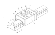
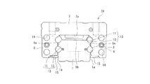
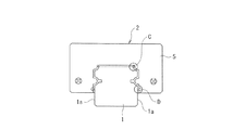
図1は、本発明に係るシール装置を備えたリニアガイド装置の一実施形態の構造を示す斜視図であり、図2は、図1のリニアガイド装置を軸方向から見た断面図である。なお、これ以降の各図においては、同一又は相当する部分には、同一の符号を付してある。
Embodiments of a seal device and a linear guide device according to the present invention will be described in detail with reference to the drawings.
[First Embodiment]
A first embodiment of the present invention will be described below.
FIG. 1 is a perspective view showing a structure of an embodiment of a linear guide device provided with a sealing device according to the present invention, and FIG. 2 is a sectional view of the linear guide device of FIG. In the following drawings, the same or corresponding parts are denoted by the same reference numerals.
軸方向に延びる断面形状略角形の案内レール1に、断面形状略コ字状のスライダ2が軸方向に移動可能に取り付けられている。なお、これらの断面とは、軸方向に直交する平面で切断した断面である。断面形状略角形の案内レール1は、外面として、軸方向両端面と、軸方向に伸びる4面とを有している。一方、スライダ2は、板状部7の両側から袖部6,6が同方向に延びてなり、板状部7と両袖部6,6とは直角をなしているため、スライダ2の断面形状は略コ字状をなしている。そして、スライダ2の内面は、板状部7の内側面7aと両袖部6,6の内側面6a,6aとからなり、スライダ2の内面の断面形状は、案内レール1の外面の断面形状に沿う形状とされている。
A
案内レール1に取り付けられたスライダ2は、その内面のうち板状部7の内側面7aが案内レール1の前記4面のうち1面1bと対向しており、両袖部6,6の内側面6a,6aが前記1面1bに隣り合う2面1a,1aとそれぞれ対向している。本発明においては、板状部7の内側面7aと対向する面1bを案内レール1の上面とし、袖部6の内側面6aと対向する面1aを案内レール1の側面とし、案内レール1の前記4面のうち上面1bと平行な面を下面とする。また、本発明においては、リニアガイド装置を軸方向端部側から見た場合に、案内レール1の中心軸線を対称中心とした両側を左右とする。
案内レール1の上面1bと左右両側面1a,1aとが交差する稜線部には、軸方向に延びる断面ほぼ1/4円弧形状の凹溝からなる転動体転動溝10,10が形成され、また、案内レール1の左右両側面1a,1aの上下方向の中間位置には、軸方向に延びる断面ほぼ半円形の凹溝からなる転動体転動溝10,10が形成されている。
The
Rolling
また、スライダ2は、スライダ本体2Aと、その軸方向両端部に着脱可能に取り付けられたエンドキャップ2B,2Bとで構成されている。さらに、スライダ2の軸方向両端部(各エンドキャップ2Bの端面)には、案内レール1とスライダ2との間に形成された空隙部の開口部分のうち軸方向に向く開口部分をシールする後述するエンドシール5,5が装着されている。
The
さらに、案内レール1の側面1a,1aに対向するスライダ2の両袖部6,6の内側面6a,6aのうち最下部近傍には、前記空隙部の開口部分のうち下方に向く開口部分(案内レール1の側面1aと、これに対向するスライダ2の袖部6の内側面6aとの間に形成された空隙部の開口部分)をシールするアンダーシール15が装着されている。これらエンドシール5,5とアンダーシール15とにより、外部から前記空隙部への異物の侵入や、スライダ2の内部で発生した粉塵の外部への排出や、前記空隙部から外部への潤滑剤の漏出が防止されている。なお、エンドシール5及びアンダーシール15が、本発明の構成要件であるシール装置に相当する。
In addition, in the vicinity of the lowermost portion of the
さらに、スライダ本体2Aの左右両袖部6,6の内側面6a,6aには、案内レール1の転動体転動溝10,10,10,10に対向する断面ほぼ半円形の凹溝からなる転動体転動溝11,11,11,11が形成されている。そして、案内レール1の転動体転動溝10,10,10,10とスライダ2の転動体転動溝11,11,11,11との間に、断面ほぼ円形の転動体転動路13,13,13,13が形成されていて、これらの転動体転動路13は軸方向に延びている。なお、案内レール1及びスライダ2が備える転動体転動溝10,11の数は片側二列に限らず、例えば片側一列又は三列以上などであってもよい。また、転動体転動溝10,11の断面形状は、前述したように単一の円弧からなる円弧状でもよいが、曲率中心の異なる2つの円弧を組合せてなる略V字状(ゴシックアーク形状溝)でもよい。
Further, the inner side surfaces 6a and 6a of the left and
この転動体転動路13内には、多数の転動体3が転動自在に装填されていて、これらの転動体3の転動を介してスライダ2が案内レール1に沿って軸方向に移動するようになっている。なお、転動体の種類はボールに限定されるものではなく、転動体としてころも使用可能である。また、転動体3の間にスペーサーを介装してもよい。
さらに、スライダ2は、スライダ本体2Aの左右両袖部6,6の肉厚部分の上部及び下部に、転動体転動路13と平行をなして軸方向に貫通する断面ほぼ円形の貫通孔からなる直線状路14,14,14,14を備えている。
A large number of rolling elements 3 are slidably loaded in the rolling
Further, the
一方、エンドキャップ2B,2Bは、例えば樹脂材料の射出成形品からなり、断面形状が略コ字状に形成されている。また、エンドキャップ2B,2Bの裏面(スライダ本体2Aとの当接面)の左右両側には、断面ほぼ円形の半ドーナツ状の湾曲路(図示せず)が上下二段に形成されている。このエンドキャップ2B,2Bをスライダ本体2Aに取り付けると、湾曲路によって転動体転動路13と直線状路14とが連通される。これら直線状路14と両端の湾曲路とで、転動体3を転動体転動路13の終点から始点へ送る転動体戻し路が構成され、転動体転動路13と前記転動体戻し路とで、略環状の転動体循環路が案内レール1を挟んで左右両側に形成される。
On the other hand, the
案内レール1に取り付けられたスライダ2が案内レール1に沿って軸方向に移動すると、転動体転動路13内に装填されている転動体3は、転動体転動路13内を転動しつつ案内レール1に対してスライダ2と同方向に移動する。そして、転動体3が転動体転動路13の終点に達すると、転動体転動路13からすくい上げられ湾曲路へ送られる。湾曲路に入った転動体3はUターンして直線状路14に導入され、直線状路14を通って反対側の湾曲路に至る。ここで再びUターンして転動体転動路13の始点に戻り、このような転動体循環路内の循環を無限に繰り返す。
When the
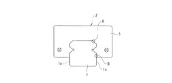
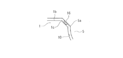
上記のような構成のリニアガイド装置は、前述したエンドシール5を備えている。このエンドシール5について、図3〜5を参照しながら説明する。図3は、本実施形態のシール装置を装着した図1のリニアガイド装置を軸方向から見た正面図である。図4は、図3のうち円で囲んだA部分を拡大して示した図である。また、図5は、図3のうち円で囲んだB部分を拡大して示した図である。
エンドシール5は、エンドキャップ2Bと同様に、断面略コ字形に形成されている。また、エンドシール5には、エンドシール5を案内レール1の軸方向に貫通する貫通孔が形成されており(図示せず)、エンドシール5は、該貫通孔を貫通する取り付けねじ(図示せず)によりスライダ2の軸方向両端部(各エンドキャップ2Bの端面)に装着されている。
The linear guide device configured as described above includes the
The
このエンドシール5は、熱可塑性樹脂等の樹脂からなる非接触型のシール装置である。すなわち、エンドシール5は、案内レール1の外面(上面1b及び両側面1a,1a)に対して所定間隔の隙間を空けて対向するように装着されていて、案内レール1とスライダ2との間に形成された空隙部の開口部分をシールしている。このエンドシール5は、案内レール1の外面と、これに対向するエンドシール5の対向面とが接触しないので、非接触型のシール装置である。
The
そして、エンドシール5のうち案内レール1の外面に対向する対向面には、対向面から案内レール1の外面に向かって突出する突起からなり、且つ、対向面からの突出長さが前記所定間隔と同一である位置決め部材16が設けられていて、案内レール1の外面に摺動可能に接している。なお、この位置決め部材16が、本発明の構成要件である位置決め部に相当する。
And the opposing surface which opposes the outer surface of the
すなわち、エンドシール5には、スライダ2の軸方向両端部(各エンドキャップ2Bの端面)に装着された時に案内レール1の上面1bと転動体転動溝10,10とが交差する稜線部1c,1cに対向する面5a,5aが形成されている。また、エンドシール5には、スライダ2の軸方向両端部(各エンドキャップ2Bの端面)に装着された時に案内レール1の左右両側面1a,1aと対向する面5b,5bが形成されている。
That is, the
そして、エンドシール5は、稜線部1c,1cに対向する面5a,5a、及び、案内レール1の左右両側面1a,1aに対向する面5b,5bに、位置決め部材16が設けられている。なお、位置決め部材16の配置される位置は、上記の位置に限定されるものではなく、傷がつくことでスライダ2の軸方向への相対移動に悪影響が出ることが考えられる転動体転動溝10や、傷が目立つ案内レール1の上面1b以外の案内レール1の外面に摺動自在に接触するように設けることができる。
The
また、エンドシール5に設ける位置決め部材16の個数は、特に限定されるものではないが、エンドシール5の上下左右方向の位置決めを適切に行うためには複数設けることが好ましい。例えば、エンドシール5の上下方向の位置決めを行う位置決め部材16は、上記のように稜線部1c,1cに対向する面5a,5aに設けることが好ましく、エンドシール5の左右方向の位置決めを行う位置決め部材16は、案内レール1の左右両側面1a,1aと対向する面5b,5bに設けることが好ましい。
The number of
さらに、位置決め部材16の材質は、接することにより案内レール1の外面に損傷を与えることがなく、且つ、スライダ2の軸方向への相対移動を妨げないようなものならば、特に限定されない。位置決め部材16の材質として、好ましくは樹脂、より好ましくは熱可塑性プラスチック、ゴム等があげられる。
さらに、位置決め部材16は、エンドシール5と一体に形成されていてもよいし、別体の位置決め部材16をエンドシール5の対向面に、接着等の慣用の固着方法により取り付けてもよい。
Further, the material of the positioning
Further, the positioning
さらに、エンドシール5と位置決め部材16が同一の材質からなる場合は、一体に成形することが好ましいが、エンドシール5と位置決め部材16の材質が同一の材質の場合でも、一体成形ではなく別体のものを接合してもよい。また、エンドシール5は、樹脂のみで構成されていてもよいが、金属等からなる芯金を備えていてもよい。
エンドシール5がこのような位置決め部材16を備えているので、リニアガイド装置を製造する際にエンドシール5の内面が案内レール1の外面に接触して損傷が生じることを防ぐことができる。すなわち、案内レール1に取り付けられたスライダ2に対してエンドシール5を装着する際に、位置決め部材16が案内レール1の外面に接触するため、案内レール1の外面とこれに対向するエンドシール5の内面(対向面)との接触が防がれる。
Further, when the
Since the
また、スライダ2にエンドシール5を装着する際に、稜線部1c,1cに対向する面5a,5aに設けられた位置決め部材16により上下方向の、案内レール1の左右両側面1a,1aと対向する面5b,5bに設けられた位置決め部材16により左右方向の位置決めを行うことができる。これにより、シム等の位置決め専用の治具を使うことなく案内レール1の外面に対するエンドシール5の位置を決めて、エンドシール5をスライダ2に取り付けることが可能となる。なお、エンドシール5をスライダ2に装着した後は、位置決め部材16を除去しても差し支えない。
Further, when the
また、本実施形態のエンドシール5に設けられた位置決め部材16の対向面からの突出長さは、案内レール1とエンドシール5との間の前記所定間隔と同一となっている。これにより、位置決め部材16の先端が案内レール1の外面に接触するようにエンドシール5をスライダ2に装着すれば、シム等の位置決め専用の治具を用いることなく、案内レール1の外面とエンドシール5の対向面との間の隙間が前記所定間隔となるように、エンドシール5をスライダ2へ取り付けることが可能である。
Further, the protruding length from the facing surface of the positioning
さらに、本実施形態のエンドシール5によれば、案内レール1に接触しているのは位置決め部材16のみであり、エンドシール5は案内レール1に非接触となるため、エンドシール5が案内レール1の外面と摺動して摺動抵抗が増加する恐れがない。また、本実施形態のエンドシール5によれば、摺動による発塵を抑えることができるため、低発塵化を実現することが可能となる。
Furthermore, according to the
また、本実施形態のエンドシール5に設けられた位置決め部材16は樹脂製であるため、案内レール1の外面と接触しても案内レール1に傷がつきにくく、スライダ2の軸方向への相対移動を妨げにくい。また、位置決め部材16が摩耗して変形をしても、エンドシール5自体はねじ等にてスライダ2に固定されているため、初期の位置を保つことが可能となる。
Further, since the positioning
〔第2実施形態〕
次に、本発明の第2実施形態について、図6〜図8を参照しながら説明する。なお、第2実施形態のリニアガイド装置の構成及び作用効果は、第1実施形態のリニアガイド装置とほぼ同様であるので、異なる部分のみ説明し、同様の部分の説明は省略する。
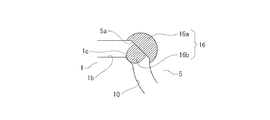
図6は、本実施形態のシール装置を装着したリニアガイド装置を軸方向から見た正面図である。図7は、図6のうち円で囲んだC部分を拡大して示した図である。また、図8は、図6におけるD部分を拡大して示した図である。
エンドシール5の案内レール1の外面に対向する対向面には、対向面から案内レール1の外面に向かって突出し、且つ、対向面からの突出長さが前記所定間隔と同一である突起16bがインサート成形により設けられていて、案内レール1の外面に摺動可能に接している。
[Second Embodiment]
Next, a second embodiment of the present invention will be described with reference to FIGS. In addition, since the structure and effect of the linear guide apparatus of 2nd Embodiment are substantially the same as the linear guide apparatus of 1st Embodiment, only a different part is demonstrated and description of the same part is abbreviate | omitted.
FIG. 6 is a front view of the linear guide device equipped with the sealing device of the present embodiment as viewed from the axial direction. FIG. 7 is an enlarged view of a portion C surrounded by a circle in FIG. FIG. 8 is an enlarged view of a portion D in FIG.
On the facing surface of the
すなわち、エンドシール5が例えば金属製である場合には、金属製のエンドシール5をインサートとしてインサート成形することにより、樹脂製の位置決め部材16をエンドシール5の対向面に設けることができる。インサート成形により成形される位置決め部材16は、ベース部16aと、ベース部16aの外面から突出する突起16bと、で構成されている。エンドシール5の対向面に形成された孔から突起16bがエンドシール5の外部に突出し、且つ、突起16bに連続するベース部16aがエンドシール5の内部に配されるように、インサート成形により位置決め部材16が成形される。この位置決め部材16の突起16bが、本発明の構成要件である位置決め部に相当する。
That is, when the
位置決め部材16をエンドシール5に設ける方法は、位置決め部材16がエンドシール5に取り付けられていれば特に限定されない。位置決め部材16をエンドシール5に設ける方法としては、接着剤を用いて位置決め部材16をベース部16aを介してエンドシール5に接着させる方法や、位置決め部材16をインサート成形する方法等があげられ、これによりエンドシール5に突起16bを設けることができる。
The method of providing the positioning
このような本実施形態のエンドシール5によれば、エンドシール5と位置決め部材16の材質を異なるものとすることができる。これにより、エンドシール5が例えば金属製のような、案内レール1に傷をつけやすいような材質であっても、エンドシール5をスライダ2に装着する際に、位置決め部材16が案内レール1に接触するため、案内レール1とエンドシール5は接触することなく、案内レール1とエンドシール5との間の隙間が前記所定間隔となるように位置決めを行うことが可能となる。なお、エンドシール5をスライダ2に装着した後は、位置決め部材16を除去しても差し支えない。
According to the
〔第3実施形態〕
次に、本発明の第3実施形態について、図9,10を参照して説明する。
なお、第3実施形態のリニアガイドの構成及び作用効果は、第1実施形態のリニアガイド装置とほぼ同様であるので、異なる部分のみ説明し、同様の部分の説明は省略する。
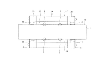
図9は、本実施形態のシール装置を装着したリニアガイド装置を下面方向から見た図である。図10は、図9のうち円で囲んだE部分を拡大して示した図である。
[Third Embodiment]
Next, a third embodiment of the present invention will be described with reference to FIGS.
In addition, since the structure and effect of the linear guide of 3rd Embodiment are substantially the same as the linear guide apparatus of 1st Embodiment, only a different part is demonstrated and description of the same part is abbreviate | omitted.
FIG. 9 is a view of the linear guide device equipped with the sealing device of the present embodiment as viewed from the lower surface side. FIG. 10 is an enlarged view of a portion E surrounded by a circle in FIG.
上記のような構成のリニアガイド装置は、前述したアンダーシール15を備えている。このアンダーシール15は、案内レール1の外面(側面1a,1a)に対して所定間隔の隙間を空けて対向するように、軸方向に沿ってスライダ2に装着されていて、案内レール1とスライダ2との間に形成された空隙部の開口部分をシールしている。このアンダーシール15は、案内レール1の外面と、これに対向するアンダーシール15の対向面15aとが接触しないので、非接触型のシール装置である。
The linear guide device configured as described above includes the above-described under
アンダーシール15をスライダ2に装着する方法は特に限定されないが、本実施形態においては、その軸方向両端部が両エンドキャップ2B,2Bに設けられたアンダーシール固定部17に保持されることにより、スライダ2に装着されている。このとき、アンダーシール15は、左右方向には移動可能に保持されている。アンダーシール固定部17の構造は、アンダーシール15を固定して保持することができるならば特に限定されないが、例えばスリットがあげられる。両エンドキャップ2B,2Bに形成されたスリット状のアンダーシール固定部17にアンダーシール15の軸方向両端部を係合させることにより、アンダーシール15が両エンドキャップ2B,2Bに保持される。
Although the method for attaching the
そして、アンダーシール15のうち案内レール1の外面に対向する対向面15aには、対向面15aから案内レール1の外面に向かって突出する突起からなり、且つ、対向面15aからの突出長さが前記所定間隔と同一である位置決め部材16が設けられていて、案内レール1の外面に摺動可能に接している。この位置決め部材16が、本発明の構成要件である位置決め部に相当する。
なお、位置決め部材16の配置される位置は、上記の位置に限定されるものではなく、傷がつくことでスライダ2の軸方向への相対移動に悪影響が出ることが考えられる転動体転動溝10以外の案内レール1の外面(側面1a)に摺動自在に接触するように設けることができる。
And the opposing
Note that the position where the positioning
また、アンダーシール15に設ける位置決め部材16の個数は、特に限定されるものではないが、アンダーシール15の位置決めを適切に行うためには複数設けることが好ましい。例えば、アンダーシール15の対向面15aの複数の軸方向位置(例えば軸方向両端部近傍)に設けることが好ましい。
さらに、位置決め部材16の材質は、接することにより案内レール1の外面に損傷を与えることがなく、且つ、スライダ2の軸方向への相対移動を妨げないようなものならば、特に限定されない。位置決め部材16の材質として、好ましくは樹脂、より好ましくは熱可塑性プラスチック、ゴム等があげられる。
Further, the number of
Further, the material of the positioning
さらに、位置決め部材16は、アンダーシール15と一体に形成されていてもよいし、別体の位置決め部材16をアンダーシール15の対向面15aに、接着等の慣用の固着方法により取り付けてもよい。
さらに、アンダーシール15と位置決め部材16が同一の材質からなる場合は、一体に成形することが好ましいが、アンダーシール15と位置決め部材16の材質が同一の材質の場合でも、一体成形ではなく別体のものを接合してもよい。また、アンダーシール15は、樹脂で構成されていてもよいし、金属で構成されていてもよい。また、樹脂で構成されている場合でも、金属等からなる芯金を備えていてもよい。
Further, the positioning
Further, when the
アンダーシール15がこのような位置決め部材16を備えているので、リニアガイド装置を製造する際にアンダーシール15の対向面15aが案内レール1の外面に接触して損傷が生じることを防ぐことができる。すなわち、案内レール1に取り付けられたスライダ2に対してアンダーシール15を装着する際に、位置決め部材16が案内レール1の外面に接触するため、案内レール1の外面とこれに対向するアンダーシール15の対向面15aとの接触が防がれる。
Since the
また、スライダ2にアンダーシール15を装着する際に、対向面15aに設けられた位置決め部材16により左右方向の位置決めを行うことができる。これにより、シム等の位置決め専用の治具を使うことなく案内レール1の外面に対するアンダーシール15の位置を決めて、アンダーシール15をスライダ2に取り付けることが可能となる。なお、アンダーシール15をスライダ2に装着した後は、位置決め部材16を除去しても差し支えない。
Further, when the
また、本実施形態のアンダーシール15に設けられた位置決め部材16の対向面15aからの突出長さは、案内レール1とアンダーシール15との間の前記所定間隔と同一となっている。これにより、位置決め部材16の先端が案内レール1の外面に接触するようにアンダーシール15をスライダ2に装着すれば、シム等の位置決め専用の治具を用いることなく、案内レール1の外面とアンダーシール15の対向面15aとの間の隙間が前記所定間隔となるように、アンダーシール15をスライダ2へ取り付けることが可能である。
Further, the protruding length of the positioning
さらに、本実施形態のアンダーシール15によれば、案内レール1に接触しているのは位置決め部材16のみであり、アンダーシール15は案内レール1に非接触となるため、アンダーシール15が案内レール1の外面と摺動して摺動抵抗が増加する恐れがない。また、本実施形態のアンダーシール15によれば、摺動による発塵を抑えることができるため、低発塵化を実現することが可能となる。
Furthermore, according to the
また、本実施形態のアンダーシール15に設けられた位置決め部材16は樹脂製であるため、案内レール1の外面と接触しても案内レール1に傷がつきにくく、スライダ2の軸方向への相対移動を妨げにくい。また、位置決め部材16が摩耗して変形をしても、アンダーシール15自体はねじ等にてスライダ2に固定されるため、初期の位置を保つことが可能となる。
In addition, since the positioning
1 案内レール
1a 側面
1b 上面
2 スライダ
2A スライダ本体
2B エンドキャップ
5 エンドシール
15 アンダーシール
16 位置決め部材
16a ベース部
16b 突起
DESCRIPTION OF
Claims (5)
前記案内レールに取り付けられた前記スライダに該シール装置を装着する際に、前記案内レールの外面に接触して、前記案内レールの外面とこれに対向する前記シール装置の対向面との接触を防ぎ、且つ、前記案内レールの外面と前記対向面との間隔を前記所定間隔に保ちつつ装着するための位置決め部を備え、該位置決め部は、前記対向面から突出する突起からなり、且つ、前記対向面からの突出長さが前記所定間隔と同一であることを特徴とするシール装置。 The slider of the linear guide device comprising: a guide rail extending in the axial direction; and a slider attached to the guide rail so as to be relatively movable in the axial direction, with a gap at a predetermined interval from the outer surface of the guide rail. In a non-contact type sealing device that is mounted so as to oppose and seals an opening portion of a gap formed between the guide rail and the slider,
When the seal device is mounted on the slider attached to the guide rail, the outer surface of the guide rail is brought into contact with the outer surface of the guide rail, thereby preventing contact between the outer surface of the guide rail and the opposite surface of the seal device. And a positioning portion for mounting the guide rail while maintaining an interval between the outer surface and the facing surface at the predetermined distance, the positioning portion including a protrusion protruding from the facing surface, and the facing A projecting length from the surface is the same as the predetermined interval.
前記シール装置を、請求項1〜4のいずれか1項に記載のシール装置とし、
前記位置決め部を前記案内レールの外面に接触させて、前記案内レールの外面とこれに対向する前記シール装置の対向面との接触を防ぎ、且つ、前記案内レールの外面と前記対向面との間隔を前記所定間隔に保ちつつ、前記案内レールに取り付けられた前記スライダに前記シール装置を装着して得たものであることを特徴とするリニアガイド装置。 A guide rail extending in the axial direction, a slider attached to the guide rail so as to be capable of relative movement in the axial direction, and mounted on the slider so as to face the outer surface of the guide rail with a predetermined gap therebetween, A linear guide device comprising: a non-contact type sealing device that seals an opening portion of a gap formed between the guide rail and the slider. The sealing device according to any one of claims 1 to 4. And the sealing device described in
The positioning portion is brought into contact with the outer surface of the guide rail to prevent contact between the outer surface of the guide rail and the opposed surface of the seal device facing the guide rail, and the distance between the outer surface of the guide rail and the opposed surface A linear guide device obtained by mounting the seal device on the slider attached to the guide rail while maintaining the predetermined distance.
Priority Applications (5)
| Application Number | Priority Date | Filing Date | Title |
|---|---|---|---|
| JP2010252222A JP5696440B2 (en) | 2010-11-10 | 2010-11-10 | Seal device and linear guide device |
| US13/881,323 US8790011B2 (en) | 2010-11-10 | 2011-09-14 | Seal device and linear guide device |
| PCT/JP2011/005196 WO2012063392A1 (en) | 2010-11-10 | 2011-09-14 | Sealing device, and linear guide device |
| CN201180001812.2A CN102612606B (en) | 2010-11-10 | 2011-09-14 | Sealing device, and linear guide device |
| KR1020137011398A KR101427544B1 (en) | 2010-11-10 | 2011-09-14 | SEALlNG DEVICE, AND LINEAR GUIDE DEVICE |
Applications Claiming Priority (1)
| Application Number | Priority Date | Filing Date | Title |
|---|---|---|---|
| JP2010252222A JP5696440B2 (en) | 2010-11-10 | 2010-11-10 | Seal device and linear guide device |
Publications (2)
| Publication Number | Publication Date |
|---|---|
| JP2012102811A true JP2012102811A (en) | 2012-05-31 |
| JP5696440B2 JP5696440B2 (en) | 2015-04-08 |
Family
ID=46050565
Family Applications (1)
| Application Number | Title | Priority Date | Filing Date |
|---|---|---|---|
| JP2010252222A Active JP5696440B2 (en) | 2010-11-10 | 2010-11-10 | Seal device and linear guide device |
Country Status (5)
| Country | Link |
|---|---|
| US (1) | US8790011B2 (en) |
| JP (1) | JP5696440B2 (en) |
| KR (1) | KR101427544B1 (en) |
| CN (1) | CN102612606B (en) |
| WO (1) | WO2012063392A1 (en) |
Cited By (2)
| Publication number | Priority date | Publication date | Assignee | Title |
|---|---|---|---|---|
| JP2014066344A (en) * | 2012-09-27 | 2014-04-17 | Nsk Ltd | Linear motion guide device |
| JP2014074478A (en) * | 2012-10-05 | 2014-04-24 | Nsk Ltd | Linear guide device |
Families Citing this family (2)
| Publication number | Priority date | Publication date | Assignee | Title |
|---|---|---|---|---|
| JP5786356B2 (en) * | 2011-02-18 | 2015-09-30 | 日本精工株式会社 | Linear motion guide device |
| CN110285141A (en) * | 2019-07-05 | 2019-09-27 | 河北维迪自动化技术有限公司 | Linear guide that self cooled is wear-resistant and guide rail slide block pair |
Citations (2)
| Publication number | Priority date | Publication date | Assignee | Title |
|---|---|---|---|---|
| JPH0651549U (en) * | 1992-12-24 | 1994-07-15 | 株式会社椿本精工 | Dust-proof sealing device for linear guide bearings |
| JP2007218357A (en) * | 2006-02-16 | 2007-08-30 | Nsk Ltd | End seal and linear guide equipped therewith |
Family Cites Families (10)
| Publication number | Priority date | Publication date | Assignee | Title |
|---|---|---|---|---|
| JPH0235050Y2 (en) * | 1985-02-08 | 1990-09-21 | ||
| JP2526061Y2 (en) * | 1990-06-20 | 1997-02-12 | 日本精工株式会社 | Dust proof device for linear guide device |
| JPH09317765A (en) * | 1996-05-27 | 1997-12-09 | Nippon Thompson Co Ltd | Direct acting rolling guide unit |
| JP4216509B2 (en) | 2002-02-20 | 2009-01-28 | Ntn株式会社 | Method for manufacturing hydrodynamic bearing device |
| JP2005226780A (en) | 2004-02-13 | 2005-08-25 | Sony Corp | Bearing unit, motor with bearing unit, and electronic device |
| CN100335805C (en) * | 2005-01-21 | 2007-09-05 | 上银科技股份有限公司 | Linear guider lubricators |
| JP2008002492A (en) * | 2006-06-20 | 2008-01-10 | Nsk Ltd | Seal for linear motion guiding bearing |
| JP2008144875A (en) * | 2006-12-11 | 2008-06-26 | Nsk Ltd | Linear guide device |
| DE102008053932A1 (en) * | 2008-10-30 | 2010-05-06 | Schaeffler Kg | linear bearings |
| JP2010169183A (en) * | 2009-01-22 | 2010-08-05 | Nsk Ltd | Linear guide device |
-
2010
- 2010-11-10 JP JP2010252222A patent/JP5696440B2/en active Active
-
2011
- 2011-09-14 WO PCT/JP2011/005196 patent/WO2012063392A1/en active Application Filing
- 2011-09-14 US US13/881,323 patent/US8790011B2/en active Active
- 2011-09-14 KR KR1020137011398A patent/KR101427544B1/en active IP Right Grant
- 2011-09-14 CN CN201180001812.2A patent/CN102612606B/en not_active Expired - Fee Related
Patent Citations (2)
| Publication number | Priority date | Publication date | Assignee | Title |
|---|---|---|---|---|
| JPH0651549U (en) * | 1992-12-24 | 1994-07-15 | 株式会社椿本精工 | Dust-proof sealing device for linear guide bearings |
| JP2007218357A (en) * | 2006-02-16 | 2007-08-30 | Nsk Ltd | End seal and linear guide equipped therewith |
Cited By (2)
| Publication number | Priority date | Publication date | Assignee | Title |
|---|---|---|---|---|
| JP2014066344A (en) * | 2012-09-27 | 2014-04-17 | Nsk Ltd | Linear motion guide device |
| JP2014074478A (en) * | 2012-10-05 | 2014-04-24 | Nsk Ltd | Linear guide device |
Also Published As
| Publication number | Publication date |
|---|---|
| CN102612606B (en) | 2015-03-11 |
| JP5696440B2 (en) | 2015-04-08 |
| WO2012063392A1 (en) | 2012-05-18 |
| US20130223770A1 (en) | 2013-08-29 |
| KR101427544B1 (en) | 2014-08-07 |
| CN102612606A (en) | 2012-07-25 |
| KR20130058079A (en) | 2013-06-03 |
| US8790011B2 (en) | 2014-07-29 |
Similar Documents
| Publication | Publication Date | Title |
|---|---|---|
| JP4938547B2 (en) | Linear motion guide unit with internal seal | |
| JP5696440B2 (en) | Seal device and linear guide device | |
| EP2388488A1 (en) | Linear guide device | |
| JP5672895B2 (en) | Attachment for temporary shaft of linear motion guide device | |
| JP2008128384A (en) | Rolling element retainer and linear guide device | |
| JP4640306B2 (en) | Linear motion guide device | |
| JP2007218357A (en) | End seal and linear guide equipped therewith | |
| JP2008002660A (en) | Linear guide | |
| US20140339779A1 (en) | Dustproof member and measurement device | |
| JP5267329B2 (en) | Linear guide device | |
| JP2015117734A (en) | Linear motion guide device | |
| JP5803220B2 (en) | Linear motion guide device | |
| JP6922703B2 (en) | Linear guidance device and its assembly method | |
| JP4770261B2 (en) | Linear motion guide device | |
| JP6816385B2 (en) | Side seal for linear motion guidance device | |
| JP2008173819A (en) | Manufacturing method of resin-made sleeve and linear guide device | |
| JP2016125600A (en) | Guide rail end face protection part of linear motion guide device and linear motion guide device | |
| WO2013073079A1 (en) | Sealing mechanism for linear guiding device | |
| JP2016160982A (en) | Dustproof cover for linear motion guide device and linear motion guide device including the same | |
| JP2022152777A (en) | Liner motion guide device | |
| JP2012107666A (en) | Track rail cover and motion guide device | |
| JP2014074478A (en) | Linear guide device | |
| JP2003120820A (en) | Seal device | |
| JP2011169377A (en) | Seal member, ball screw having seal member, and method for manufacturing seal member | |
| JP2009209964A (en) | Rolling guide device |
Legal Events
| Date | Code | Title | Description |
|---|---|---|---|
| A621 | Written request for application examination |
Free format text: JAPANESE INTERMEDIATE CODE: A621 Effective date: 20131107 |
|
| A131 | Notification of reasons for refusal |
Free format text: JAPANESE INTERMEDIATE CODE: A131 Effective date: 20140909 |
|
| A521 | Request for written amendment filed |
Free format text: JAPANESE INTERMEDIATE CODE: A523 Effective date: 20141105 |
|
| TRDD | Decision of grant or rejection written | ||
| A01 | Written decision to grant a patent or to grant a registration (utility model) |
Free format text: JAPANESE INTERMEDIATE CODE: A01 Effective date: 20150113 |
|
| A61 | First payment of annual fees (during grant procedure) |
Free format text: JAPANESE INTERMEDIATE CODE: A61 Effective date: 20150126 |
|
| R150 | Certificate of patent or registration of utility model |
Ref document number: 5696440 Country of ref document: JP Free format text: JAPANESE INTERMEDIATE CODE: R150 |