JP2012102779A - Check valve with orifice - Google Patents
Check valve with orifice Download PDFInfo
- Publication number
- JP2012102779A JP2012102779A JP2010250462A JP2010250462A JP2012102779A JP 2012102779 A JP2012102779 A JP 2012102779A JP 2010250462 A JP2010250462 A JP 2010250462A JP 2010250462 A JP2010250462 A JP 2010250462A JP 2012102779 A JP2012102779 A JP 2012102779A
- Authority
- JP
- Japan
- Prior art keywords
- orifice
- check valve
- casing
- lid
- valve
- Prior art date
- Legal status (The legal status is an assumption and is not a legal conclusion. Google has not performed a legal analysis and makes no representation as to the accuracy of the status listed.)
- Granted
Links
- 238000007789 sealing Methods 0.000 claims abstract description 8
- XLYOFNOQVPJJNP-UHFFFAOYSA-N water Substances O XLYOFNOQVPJJNP-UHFFFAOYSA-N 0.000 claims description 15
- 239000012530 fluid Substances 0.000 abstract description 12
- 230000002093 peripheral effect Effects 0.000 description 15
- 238000011144 upstream manufacturing Methods 0.000 description 14
- 239000011347 resin Substances 0.000 description 4
- 229920005989 resin Polymers 0.000 description 4
- 239000007788 liquid Substances 0.000 description 3
- 238000012856 packing Methods 0.000 description 2
- 230000002265 prevention Effects 0.000 description 2
- 230000000149 penetrating effect Effects 0.000 description 1
- 238000004904 shortening Methods 0.000 description 1
Images


Landscapes
- Valve Housings (AREA)
- Lift Valve (AREA)
- Check Valves (AREA)
- Details Of Valves (AREA)
Abstract
Description
本発明は、圧力や流量を調整するオリフィスと流体の逆流を防止するチェッキ弁とを一体としたオリフィス付チェッキ弁に関する。 The present invention relates to a check valve with an orifice in which an orifice that adjusts pressure and flow rate and a check valve that prevents backflow of fluid are integrated.
従来、圧力や流量を調整するオリフィスと流体の逆流を防ぐチェッキ弁は、一般に、それぞれ独立した部品として、例えば吐出し配管に各々個別に設置されるように構成されており、このため、オリフィスとチェッキ弁とを備えた配管の短小化を図る上での妨げとなっていた。 Conventionally, an orifice that adjusts the pressure and flow rate and a check valve that prevents backflow of fluid are generally configured as independent components, for example, individually installed in a discharge pipe. This has been an obstacle to shortening the piping provided with the check valve.
このため、流体吐出し側に連通する開口を有する本体と、この本体の開口を開閉可能な弁体と、本体の開口の閉位置へ弁体を付勢すると弾性体とから構成され、入口側に絞り部(オリフィス)を一体に設けた逆止弁(オリフィス付チェッキ弁)が開発されている(特許文献1参照)。 Therefore, the main body has an opening communicating with the fluid discharge side, a valve body capable of opening and closing the opening of the main body, and an elastic body when the valve body is biased to a closed position of the opening of the main body. In addition, a check valve (orifice check valve) in which a throttle portion (orifice) is integrally provided is developed (see Patent Document 1).
特許文献1に記載の逆止弁(オリフィス付チェッキ弁)は、入口側に絞り部(オリフィス)を一体に設けているため、オリフィスとチェッキ弁とを別々に繋げた場合に比較して、装置としての小型化に貢献することができる。しかし、気体を対象として、気体が一方へ流れ出ればよい構成を採用しており、液体を対象としている場合のように、吐出し側の圧力と流量を目的にあわせて容易に変更できるようにしたものではない。 The check valve (check valve with orifice) described in Patent Document 1 is provided with a throttle portion (orifice) integrally on the inlet side, and therefore, compared with a case where the orifice and the check valve are separately connected, As a result, it can contribute to downsizing. However, a configuration that only requires gas to flow out to one side is adopted for gas, so that the pressure and flow rate on the discharge side can be easily changed according to the purpose, as in the case of liquid. It was n’t.
つまり、特許文献1に記載の逆止弁の場合、逆止弁自体を交換することなく、吐出し側の圧力や流量を変更するためには、例えばコンプレッサ等の装置から逆止弁(オリフィス付チェッキ弁)を取出してオリフィス部のリテーナ(Cリング)を取外し、オリフィスを有する部品をオリフィス部から引出した後、目的とする径のオリフィスを有する部品をオリフィス部に組込んでリテーナ(Cリング)で固定し、装置に再度組込むといった煩雑な操作を行う必要がある。 That is, in the case of the check valve described in Patent Document 1, in order to change the pressure and flow rate on the discharge side without replacing the check valve itself, for example, a check valve (with an orifice) is used from a device such as a compressor. Take out the check valve), remove the retainer (C-ring) of the orifice part, pull out the part with the orifice from the orifice part, and then incorporate the part with the orifice of the desired diameter into the orifice part (C-ring) It is necessary to perform a complicated operation such as fixing with a screw and re-installing the device.
しかも、特許文献1に記載の逆止弁は、例えば装置の一部に取付ける構造が採用されており、配管の途中に取付ける構造とはなっていないため、配管の一部に使用することができず、また、専用部品であるため、配管に組込むことが一般に困難である。 Moreover, the check valve described in Patent Document 1 employs a structure that is attached to a part of the apparatus, for example, and is not structured to be attached in the middle of the pipe, and therefore can be used for a part of the pipe. In addition, since it is a dedicated part, it is generally difficult to incorporate it into piping.
更に、1つのオリフィスで急激な減圧を行うとキャビテーションが発生し、その騒音が問題になる場合があり、このため、オリフィスを容易に追加して、吐出し側の十分な減圧や流量の更なる絞り込みを行えるようにすることが望まれている。しかし、特許文献1に記載の逆止弁は、このような要請に応えることが困難であると考えられる。 Furthermore, sudden pressure reduction with one orifice may cause cavitation and noise, which may cause problems. For this reason, it is easy to add an orifice to achieve sufficient pressure reduction and flow rate on the discharge side. It is desired to be able to narrow down. However, the check valve described in Patent Document 1 is considered to be difficult to meet such a request.
本発明は上記事情に鑑みて為されたもので、弁自体を交換することなく、比較的簡単な操作で、吐出し側の圧力や流量を容易かつ簡便に変更でき、しかも配管の途中への取付けやオリフィスの追加を容易に行えるようにしたオリフィス付チェッキ弁を提供することを目的とする。 The present invention has been made in view of the above circumstances, and the pressure and flow rate on the discharge side can be easily and easily changed by a relatively simple operation without replacing the valve itself. It is an object of the present invention to provide a check valve with an orifice that can be easily attached and added with an orifice.
請求項1に記載の発明は、オリフィスが開口された蓋体と、弁体及び該弁体を一方向に付勢する弾性体を内蔵するケーシングとを備え、前記蓋体及び前記ケーシングには、互いに螺合して前記ケーシングの端部に前記蓋体を連結するねじ部がそれぞれ形成され、前記ケーシングの端部に前記蓋体を連結した時に前記ケーシング内の前記弁体が前記蓋体に向けて付勢するように構成されることを特徴とするオリフィス付チェッキ弁である。 The invention according to claim 1 includes a lid body in which an orifice is opened, and a casing containing a valve body and an elastic body that urges the valve body in one direction. The lid body and the casing include: Threaded portions are formed to connect the lid body to the end portion of the casing, and the valve body in the casing faces the lid body when the lid body is connected to the end portion of the casing. It is a check valve with an orifice characterized by being comprised so that it may urge.
これにより、ケーシング及び蓋体にそれぞれ設けた互いに螺合するねじ部を介して、ケーシングに連結されていた第1の径のオリフィスを開口させた蓋体を、第1の径とは異なる第2の径のオリフィスを開口させた他の蓋体に交換することで、弁全体を交換することなく、オリフィス付チェッキ弁の吐出し側の圧力や流量を容易かつ簡便に変更することができる。 As a result, the lid having the opening of the first diameter orifice connected to the casing through the threaded portion of the casing and the lid respectively screwed to each other is different from the first diameter. By exchanging with another lid having an orifice having a diameter of, the pressure and flow rate on the discharge side of the check valve with orifice can be easily and simply changed without replacing the entire valve.
請求項2に記載の発明は、前記弁体のシール面には、該弁体と一体となって動作する弁座が取外し可能に備えられていることを特徴とする請求項1に記載のオリフィス付チェッキ弁である。 According to a second aspect of the present invention, there is provided the orifice according to the first aspect, wherein a valve seat that operates integrally with the valve body is detachably provided on the sealing surface of the valve body. This is a check valve.
これにより、シール性能に優れた、例えば樹脂やゴム製の弁座を使用して弁体(弁座)のシール性を向上させ、しかも弁座が摩耗した時に弁座のみを交換することが可能となる。また、樹脂やゴム製等の騒音の発生を抑えられる弁座を使用することで、弁開閉時の作動音を低減させて騒音を低下させることができる。 This makes it possible to improve the sealing performance of the valve body (valve seat) using a valve seat made of resin or rubber, for example, with excellent sealing performance, and it is possible to replace only the valve seat when the valve seat is worn. It becomes. In addition, by using a valve seat that can suppress the generation of noise, such as resin or rubber, it is possible to reduce the noise by reducing the operating noise when the valve is opened and closed.
請求項3に記載の発明は、前記ケーシングの端部に前記蓋体を連結した時に外部に開口する前記ケーシング及び前記蓋体の開口端には配管用ねじ穴がそれぞれ形成されていることを特徴とする請求項1または2記載のオリフィス付チェッキ弁である。 The invention according to claim 3 is characterized in that a screw hole for piping is formed in each of the casing and the opening end of the lid that opens to the outside when the lid is connected to the end of the casing. The check valve with an orifice according to claim 1 or 2.
これにより、ケーシングの開口端に形成した配管用ねじ穴を介して該ケーシングを一方の配管に、蓋体の開口端に形成した配管用ねじ穴を介して該蓋体を他方の配管にそれぞれ連結することで、オリフィス付チェッキ弁を配管の途中に容易に取付けて、配管の一部となすことができる。 As a result, the casing is connected to one pipe via a pipe screw hole formed at the open end of the casing, and the lid is connected to the other pipe via a pipe screw hole formed at the open end of the lid. By doing so, the check valve with an orifice can be easily attached in the middle of the pipe to be a part of the pipe.
請求項4に記載の発明は、前記ケーシングの出口側にオリフィスを設けたことを特徴とする請求項1乃至3のいずれかに記載のオリフィス付チェッキ弁である。
このように、ケーシングの出口側にもオリフィスを設けることで、オリフィスの数を増やしたいとの要請に応え、例えばキャビテーションの発生を抑えながら、オリフィス付チェッキ弁の吐出し側の圧力や流量をより正確に調整することができる。
The invention according to claim 4 is the check valve with an orifice according to any one of claims 1 to 3, wherein an orifice is provided on an outlet side of the casing.
In this way, by providing an orifice on the outlet side of the casing, the demand for increasing the number of orifices is met. It can be adjusted accurately.
請求項5に記載の発明は、ポンプと、前記ポンプの吐出し側配管に取付けられる請求項1乃至4のいずれかに記載のオリフィス付チェッキ弁を有することを特徴とする給水装置である。 A fifth aspect of the present invention is a water supply apparatus comprising the pump and the check valve with an orifice according to any one of the first to fourth aspects attached to a discharge side pipe of the pump.
給水装置にあっては、締切運転時の水温上昇を防止するために、ポンプの吐出し側配管に、水温上昇防止逃し装置としてオリフィスを取付けることが広く行われる。このため、ポンプの吐出し側配管に請求項1乃至4のいずれかに記載のオリフィス付チェッキ弁を取付けて、オリフィス付チェッキ弁のケーシングにねじ部を介して連結されていた第1の径のオリフィスを開口させた蓋体を、第1の径とは異なる第2の径のオリフィスを開口させた他の蓋体に簡易に交換することで、逃し水量を容易に調整することができる。 In a water supply apparatus, in order to prevent an increase in water temperature during a shut-off operation, an orifice is widely attached to a discharge side pipe of a pump as a water temperature increase prevention escape device. Therefore, the check valve with an orifice according to any one of claims 1 to 4 is attached to a discharge side pipe of the pump, and the first diameter of the first check valve connected to the casing of the check valve with an orifice via a screw portion is provided. By simply replacing the lid with the orifice opened with another lid with an orifice having a second diameter different from the first diameter, the amount of water to be discharged can be easily adjusted.
本発明のオリフィス付チェッキ弁によれば、ケーシング及び蓋体にそれぞれ設けた互いに螺合するねじ部を介して、ケーシングに連結されていた第1の径のオリフィスを開口させた蓋体を、第1の径とは異なる第2の径のオリフィスを開口させた他の蓋体に交換することで、弁全体を交換することなく、オリフィス付チェッキ弁の吐出し側の圧力や流量を容易に変更することができる。 According to the check valve with an orifice of the present invention, the lid body in which the orifice having the first diameter connected to the casing is opened via the screw portions that are screwed to each other provided in the casing and the lid body. Easily change the pressure and flow rate on the discharge side of the check valve with an orifice without replacing the entire valve by replacing it with another lid that has an orifice with a second diameter different from the diameter of 1. can do.
以下、本発明の実施形態を図面を参照して説明する。なお、以下の各例において、同一または相当する部材には同一符号を付して重複した説明を省略する。 Hereinafter, embodiments of the present invention will be described with reference to the drawings. In the following examples, the same or corresponding members are denoted by the same reference numerals, and redundant description is omitted.
図1は、本発明の実施形態のオリフィス付チェッキ弁の縦断正面図である。図1に示すように、この例のオリフィス付チェッキ弁10は、流れ方向(軸方向)に貫通する貫通孔を内部に有する蓋体20と、蓋体20との間でチェッキ弁を構成する略円筒状のケーシング30とから主に構成されている。
FIG. 1 is a longitudinal front view of an orifice check valve according to an embodiment of the present invention. As shown in FIG. 1, the
蓋体20の流れ方向に沿った入口側の内周面には、配管との連結に使用される配管用ねじ部21が、流れ方向に沿った出口側の内周面には、流路形成穴22がそれぞれ設けられ、配管用ねじ部21と流路形成穴22は、所定の径(オリフィス径)DAを有するオリフィス23で互いに連通している。これにより、蓋体20の内部に貫通孔が形成され、蓋体20の内部に流入した流体は、蓋体20の貫通穴内を流れ方向に沿って流れ、オリフィス23を通過することで、吐出し側の圧力や流量が調整される。このため、径(オリフィス径)DAの異なるオリフィス23を有する蓋体20を使用することで、つまり、例えば、径(オリフィス径)DAがD1(DA=D1)のオリフィス23を有する蓋体20から、径(オリフィス径)DAがD2(DA=D2,D1≠D2)のオリフィス23を有する他の蓋体20に交換することで、吐出し側の圧力や流量が変化する。
On the inner peripheral surface on the inlet side along the flow direction of the
蓋体20の外周面の軸方向に沿った所定位置にはフランジ24が設けられ、このフランジ24を挟んで、蓋体20の流れ方向に沿った出口側の外周面には、雄ねじ部25が設けられている。更に、蓋体20の内周面に設けられた流路形成穴22の流れ方向に沿った出口側端部には、流れ方向に沿って内径がテーパ状に徐々に拡径する当接面(シール面)26が形成されている。
A
ケーシング30の内周面の流れ方向に沿った出口側には、配管との連結に使用される配管用ねじ部31が、横断面円形の収納部32に連通して設けられ、流れ方向に沿った入口側の内周面には、蓋体20の流れ方向に沿った出口側の外周面に設けた雄ねじ部25と螺合する雌ねじ部33が設けられている。これによって、ケーシング30に設けた雌ねじ部33に蓋体20に設けた雄ねじ部25を螺合することで、ケーシング30の端部に蓋体20を連結し、しかも、蓋体20のケーシング30への取付けや、蓋体20のケーシング30からの取外しを、互いに螺合するねじ部25,33を介して容易かつ簡便に行えるように構成されている。この例にあっては、蓋体20のフランジ24とケーシング30の流れ方向入口側端面との間に、流体の漏れを防止するパッキン40が介装される。
On the outlet side along the flow direction of the inner peripheral surface of the
ケーシング30の収納部32内には、流れ方向に沿った上流側に位置して弁体50が、下流側に位置して弁体50を流れ方向の上流側に向けて付勢する、スプリングからなる弾性体60がそれぞれ収納され、ケーシング30の端部に蓋体20を連結することで、弁体50及び弾性体60の脱出が防止されるようになっている。弁体50は、流れ方向に沿った上流側に位置する略円柱状の頭部51と、下流側に位置して弾性体60の端部を収納する略円筒状の収納部52とを有しており、頭部51と収納部52とは、この例では、円周方向に沿った4箇所に開口部53を有する円筒状の軸部54で連結されている。
In the
弁体50の頭部51の流れ方向に沿った上流側端面には、座金70及びボルト72によって、例えばゴムまたは樹脂製の弁座80が取外し可能に取付けられ、この弁座80の流れ方向に沿った上流側外周面には、前記蓋体20の流れ方向の下流側内周面に設けられた当接面26に対応して、流れ方向に沿って外径が徐々に拡径するテーパ状の当接面(シール面)82が形成されている。
A
これにより、蓋体20のオリフィス23を通過して該オリフィス23の下流側に流入した流体の圧力が、弁体50を流れ方向の上流側に向けて付勢する弾性体60の弾性力に打ち勝った時に、オリフィス付チェッキ弁10内の流路が開き、それ以外は、オリフィス付チェッキ弁10内の流路が閉じる。
As a result, the pressure of the fluid flowing through the
つまり、オリフィス23の下流側に流入した流体の圧力が弾性体60の弾性力に打ち勝った時、弁体50は、流体の流れに押されて流れ方向に沿って後退し、これによって、弁座80の当接面82と蓋体20の当接面26との間に隙間ができ、オリフィス23の下流側に流入した流体は、この隙間及び弁体50の軸部54に設けた開口部53を通過して、ケーシング30から外部に流出する。弾性体60の弾性力がオリフィス23の下流側に流入した流体の圧力に打ち勝った時には、弁体50は、弾性体60の弾性力に押されて流れ方向前方に向けて前進し、弁座80の当接面82を蓋体20の当接面26に当接(圧接)させ、これによって、オリフィス付チェッキ弁10内の流路を閉じる。
That is, when the pressure of the fluid flowing into the downstream side of the
上記構成のオリフィス付チェッキ弁10は、流れ方向の上流側に位置する配管に蓋体20の配管用ねじ部21を、流れ方向の下流側に位置する配管にケーシング30の配管用ねじ部31をそれぞれ連結して使用される。そして、特に、液体を対象とする場合に、吐出し側の圧力と流量を目的にあわせ変更したいとの要請に応えることができる。
The check valve with an
つまり、このような場合に、ケーシング30の端部に取付けられている、例えば径DAがD1のオリフィス23を有する蓋体20とは異なる、例えば径DAがD2(D1≠D2)のオリフィスを有する新たな蓋体を用意し、ケーシング30の端部から蓋体20を取外した後、ケーシング30の端部に新たな蓋体を取付けることによって、吐出し側の圧力や流量を変えることができる。このケーシング30の端部からの蓋体20の取外し、及びケーシング30の端部への新たな蓋体の取付けを、蓋体20及びケーシング30にそれぞれ設けた互いに螺合するねじ部25,33を介して容易且つ簡便に行うことができる。
That is, in such a case, for example, the diameter D A is different from the
この例では、弁体50の頭部51の流れ方向に沿った上流側端面に、弁座80を取外し可能に取付けている。これによって、オリフィス付チェッキ弁10の内部を液体が流れる場合に、異物の噛込み等により、弁座80の当接面(シール面)82に摩耗が生じても、摩耗が生じた弁座80を容易に交換できるようにしている。しかも、シール性能に優れ、騒音の発生を抑えられる、例えば樹脂やゴム製の弁座80を使用することで、弁座80のシール性を向上させるとともに、弁開閉時の作動音を低減させて騒音を低下させることができる。
In this example, the
また、ケーシング30の流れ方向の下流側に形成した配管用ねじ穴31を介してケーシング30を一方の配管に、蓋体20の流れ方向の上流側の開口端に形成した配管用ねじ穴21を介して蓋体20を他方の配管にそれぞれ連結することで、オリフィス付チェッキ弁10を配管の途中に容易に取付けて配管の一部となすことができる。
In addition, the
上記の例では、ケーシング30の流れ方向の上流側端部に、内部にオリフィス23を設けた蓋体20を連結するようにした例を示しているが、蓋体20の流れ方向下流側端部に連結されるケーシング30側に蓋体としての役割を行わせるようにしてもよい。
In the above example, an example is shown in which the
また、弁体50の移動量を調整して、オリフィス付チェッキ弁10の内部を流れる流体を減圧したり、流量を調整したりすることもできる。この弁体50の移動量の調整は、(1)オリフィス23が開口された蓋体20の当接面(シール面)26の位置(長さ)を調整する、(2)弁体50の長さを調整する、(3)弾性体60の弾性力(強さ)を調整する、ことによって行うことができる。このことは、以下の各例に同様である。
In addition, the amount of movement of the
図2は、本発明の他の実施形態のオリフィス付チェッキ弁の縦断正面図を示す。この例のオリフィス付チェッキ弁10aの図1に示すオリフィス付チェッキ弁10と異なる点は、ケーシング30の出口側、つまりケーシング30の配管用ねじ部31と収納部32の間にも、所定の径(オリフィス径)DBを有するオリフィス34を設けた点にある。このように、ケーシング30の下流側にもオリフィス34を設けることで、2つのオリフィス23,34で正確かつ容易に吐出し側の圧力や流量を制御することができる。
FIG. 2: shows the longitudinal front view of the check valve with an orifice of other embodiment of this invention. The check valve with
なお、例えば蓋体20と同形状の内部にオリフィス23を有する部品を、オリフィス付チェッキ弁10aの蓋体20の流れ方向の上流側やケーシング30の流れ方向の下流側に接続することで、3段、4段とオリフィスを追加することが可能になる。これにより、更に減圧したり、流量を制御したりしたい場合に対処することができる。
For example, by connecting a part having an
図3は、本発明の更に他の実施形態のオリフィス付チェッキ弁の縦断正面図を示す。この例のオリフィス付チェッキ弁10bの図2に示すオリフィス付チェッキ弁10aと異なる点は、ケーシング30の内部の収納部32とオリフィス34との間に、90°流れ方向を生えるエルボ状流路35を形成した点にある。このように、ケーシング30の内部にエルボ状流路35を形成することで、配管側にエルボを用いることなく、流れ方向を90°変えることができ、これによって、配管スペースをよりコンパクトにすることができる。
FIG. 3 is a longitudinal front view of a check valve with an orifice according to still another embodiment of the present invention. The check valve with
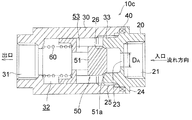
図4は、本発明の更に他の実施形態のオリフィス付チェッキ弁の縦断正面図を示す。この例のオリフィス付チェッキ弁10cの図1に示すオリフィス付チェッキ弁10と異なる点は、弁体50の頭部51に弁体80を取外し自在に設けることなく、弁体50の頭部51の流れ方向上流側端面に、蓋体20の流れ方向の下流側内周面に設けられた当接面26に対応して、流れ方向に沿って外径が徐々に拡径するテーパ状の当接面(シール面)51aを形成している点にある。
このように、弁体50の頭部51に当接面(シール面)51aを直接設けることで、構造の簡素化を図ることができる。
FIG. 4: shows the longitudinal front view of the check valve with an orifice of other embodiment of this invention. The check valve with
In this way, by directly providing the contact surface (seal surface) 51a on the
図5は、本発明の更に他の実施形態のオリフィス付チェッキ弁の縦断正面図を示す。この例のオリフィス付チェッキ弁10dの図1に示すオリフィス付チェッキ弁10と異なる点は、蓋体20として、流れ方向の下流側の外周面に設けた雄ねじ部25の代わりに、流れ方向の下流側の内周面に雌ねじ部27を設けたものを、ケーシング30として、流れ方向の上流側の内周面に設けた雌ねじ部33の代わりに、流れ方向の上流側の外周面に雄ねじ部36を設けたものをそれぞれ使用し、ケーシング30の雄ねじ部36に蓋体20の雌ねじ部を27を螺合させることで、ケーシング30の端部に蓋体20を連結するようにした点にある。
FIG. 5: shows the longitudinal front view of the check valve with an orifice of other embodiment of this invention. The difference between the check valve with
このように、互いに螺合する雄ねじ部及び雌ねじ部の一方をケーシング30に、他方を蓋体20にそれぞれ設けることで、ケーシング30の端部への蓋体20の取付けや、ケーシング30の端部からの蓋体20の取外しを、ねじ部を介して容易且つ簡便に行うことができる。
In this manner, by providing one of the male screw portion and the female screw portion that are screwed together in the
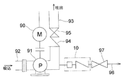
図6は、例えば図1に示すオリフィスチェッキ弁10を設置した給水装置の要部を示す。つまり、給水装置には、モータ90の駆動に伴って作動するポンプ91を有し、このポンプ91の吸込口に吸込管92が、吐出し口に吐出し管93がそれぞれ接続され、ポンプ91の吐出し口と吐出し管93との間に、チェッキ弁94と仕切弁95が介装されている。更に、ポンプ91の吐出し側には、呼水槽や受水槽に水を戻したり、そのまま排水したりする排水管96が接続され、この排水管96に図1に示すオリフィスチェッキ弁10と仕切弁97が設置されている。
FIG. 6 shows a main part of a water supply apparatus in which, for example, the
なお、図1に示すオリフィスチェッキ弁10の代わりに、図2乃至図5に示すオリフィスチェッキ弁10a〜10dのいずれかを使用しても良いことは勿論である。
Of course, any one of the
本発明のオリフィス付チェッキ弁は、主に給水装置や消火ポンプ装置等のポンプの吐出し側に取付けられる。給水装置や消火ポンプ装置は、締切運転時の水温上昇を防止するために、吐出し側配管に、水温上昇防止逃し装置としてオリフィスを取付けることが広く行われる。このため、図6に示すように、本発明のオリフィス付チェッキ弁10をポンプ91の吐出し側の排水管96に設置し、前述のように、蓋体20のみを交換することで、吐出し側の圧力や流量を簡単に変えることができるようすることで、逃し水量を容易に調整することができる。
The check valve with an orifice of the present invention is attached mainly to a discharge side of a pump such as a water supply device or a fire extinguishing pump device. In order to prevent an increase in water temperature during a shutoff operation, a water supply device or a fire pump device is widely used to attach an orifice as a water temperature increase prevention escape device to the discharge side pipe. For this reason, as shown in FIG. 6, the check valve with
これまで本発明の一実施形態について説明したが、本発明は上述の実施形態に限定されず、その技術的思想の範囲内において種々異なる形態にて実施されてよいことはいうまでもない。 Although one embodiment of the present invention has been described so far, it is needless to say that the present invention is not limited to the above-described embodiment, and may be implemented in various forms within the scope of the technical idea.
10,10a,10b,10c,10d オリフィス付チェッキ弁
20 蓋体
21 配管用ねじ部
23 オリフィス
25 雄ねじ部
26 当接面(シール面)
27 雌ねじ部
30 ケーシング
31 配管用ねじ部
33 雌ねじ部
34 オリフィス
36 雄ねじ部
40 パッキン
50 弁体
51 頭部
51a 当接面(シール面)
53 開口部
60 弾性体
80 弁座
82 当接面(シール面)
10, 10a, 10b, 10c, 10d Check valve with
27
53
Claims (5)
弁体及び該弁体を一方向に付勢する弾性体を内蔵するケーシングとを備え、
前記蓋体及び前記ケーシングには、互いに螺合して前記ケーシングの端部に前記蓋体を連結するねじ部がそれぞれ形成され、
前記ケーシングの端部に前記蓋体を連結した時に前記ケーシング内の前記弁体が前記蓋体に向けて付勢するように構成されることを特徴とするオリフィス付チェッキ弁。 A lid with an orifice open;
A casing containing a valve body and an elastic body that biases the valve body in one direction,
The lid body and the casing are each formed with a thread portion that is screwed together to connect the lid body to an end portion of the casing,
A check valve with an orifice, wherein the valve body in the casing is urged toward the lid when the lid is connected to an end of the casing.
前記ポンプの吐出し側配管に取付けられる請求項1乃至4のいずれかに記載のオリフィス付チェッキ弁を有することを特徴とする給水装置。 A pump,
5. A water supply apparatus comprising the check valve with an orifice according to any one of claims 1 to 4, which is attached to a discharge side pipe of the pump.
Priority Applications (1)
| Application Number | Priority Date | Filing Date | Title |
|---|---|---|---|
| JP2010250462A JP5688269B2 (en) | 2010-11-09 | 2010-11-09 | Check valve with orifice |
Applications Claiming Priority (1)
| Application Number | Priority Date | Filing Date | Title |
|---|---|---|---|
| JP2010250462A JP5688269B2 (en) | 2010-11-09 | 2010-11-09 | Check valve with orifice |
Publications (2)
| Publication Number | Publication Date |
|---|---|
| JP2012102779A true JP2012102779A (en) | 2012-05-31 |
| JP5688269B2 JP5688269B2 (en) | 2015-03-25 |
Family
ID=46393418
Family Applications (1)
| Application Number | Title | Priority Date | Filing Date |
|---|---|---|---|
| JP2010250462A Active JP5688269B2 (en) | 2010-11-09 | 2010-11-09 | Check valve with orifice |
Country Status (1)
| Country | Link |
|---|---|
| JP (1) | JP5688269B2 (en) |
Cited By (3)
| Publication number | Priority date | Publication date | Assignee | Title |
|---|---|---|---|---|
| CN107084264A (en) * | 2017-05-18 | 2017-08-22 | 长沙执先智量科技股份有限公司 | A kind of sanitation-grade check valve |
| US10247183B2 (en) | 2013-03-13 | 2019-04-02 | Howden Thomassen Compressors Bv | Horizontal piston compressor |
| KR20200082866A (en) * | 2018-12-31 | 2020-07-08 | 주식회사 디쌤 | Coupler |
Families Citing this family (1)
| Publication number | Priority date | Publication date | Assignee | Title |
|---|---|---|---|---|
| CN105605269A (en) * | 2013-10-23 | 2016-05-25 | 南安市丽迪家居用品有限公司 | Water-saving connector capable of adjusting maximum water flow |
Citations (6)
| Publication number | Priority date | Publication date | Assignee | Title |
|---|---|---|---|---|
| JPH0439473A (en) * | 1990-06-05 | 1992-02-10 | Kitz Corp | Check valve |
| JPH05302680A (en) * | 1992-02-28 | 1993-11-16 | Yokogawa Electric Corp | Check valve |
| JPH07310837A (en) * | 1994-05-16 | 1995-11-28 | Okano Valve Seizo Kk | Swing check valve |
| JP2000179713A (en) * | 1998-12-14 | 2000-06-27 | Ebara Corp | Valve device |
| JP2003021260A (en) * | 2001-07-05 | 2003-01-24 | Sayama Seisakusho:Kk | Backflow preventing unit |
| JP2003156175A (en) * | 2001-11-21 | 2003-05-30 | Sayama Seisakusho:Kk | Backflow preventive unit |
-
2010
- 2010-11-09 JP JP2010250462A patent/JP5688269B2/en active Active
Patent Citations (6)
| Publication number | Priority date | Publication date | Assignee | Title |
|---|---|---|---|---|
| JPH0439473A (en) * | 1990-06-05 | 1992-02-10 | Kitz Corp | Check valve |
| JPH05302680A (en) * | 1992-02-28 | 1993-11-16 | Yokogawa Electric Corp | Check valve |
| JPH07310837A (en) * | 1994-05-16 | 1995-11-28 | Okano Valve Seizo Kk | Swing check valve |
| JP2000179713A (en) * | 1998-12-14 | 2000-06-27 | Ebara Corp | Valve device |
| JP2003021260A (en) * | 2001-07-05 | 2003-01-24 | Sayama Seisakusho:Kk | Backflow preventing unit |
| JP2003156175A (en) * | 2001-11-21 | 2003-05-30 | Sayama Seisakusho:Kk | Backflow preventive unit |
Cited By (4)
| Publication number | Priority date | Publication date | Assignee | Title |
|---|---|---|---|---|
| US10247183B2 (en) | 2013-03-13 | 2019-04-02 | Howden Thomassen Compressors Bv | Horizontal piston compressor |
| CN107084264A (en) * | 2017-05-18 | 2017-08-22 | 长沙执先智量科技股份有限公司 | A kind of sanitation-grade check valve |
| KR20200082866A (en) * | 2018-12-31 | 2020-07-08 | 주식회사 디쌤 | Coupler |
| KR102163629B1 (en) | 2018-12-31 | 2020-10-08 | 주식회사 디쌤 | Coupler |
Also Published As
| Publication number | Publication date |
|---|---|
| JP5688269B2 (en) | 2015-03-25 |
Similar Documents
| Publication | Publication Date | Title |
|---|---|---|
| JP5189403B2 (en) | Backflow prevention device | |
| JP6058672B2 (en) | Fluid mixing delivery system | |
| CN106368999B (en) | Loop flushing system for hydrostatic equipment | |
| WO2008029051A3 (en) | Liquid delivery device comprising a pump and a valve | |
| JP5688269B2 (en) | Check valve with orifice | |
| JP2014181765A (en) | Check valve | |
| US7004186B2 (en) | Surge relief apparatus for a valve | |
| CN202012642U (en) | Novel backflow preventer | |
| RU182640U1 (en) | CHECK VALVE | |
| US20140026986A1 (en) | Non chattering pressure relief valve | |
| US20210299598A1 (en) | Fuel filter assembly | |
| CN108180297B (en) | Anti-flutter one-way valve | |
| CN210859941U (en) | High-pressure reducing valve | |
| CN203309243U (en) | Valve excessive pressure prevention device | |
| JP2006509165A (en) | Backflow preventer | |
| RU189281U1 (en) | CHECK VALVE | |
| JP2018105382A (en) | Water conduction tool and water heater | |
| CN110762261A (en) | Multifunctional industrial valve | |
| CN202001671U (en) | Right-angled pressure reduction type backflow preventer | |
| JP7267669B2 (en) | piping connection member | |
| JP4494200B2 (en) | High pressure fluid container structure with pressure pump | |
| CN103994252A (en) | Valve | |
| RU2614439C1 (en) | Shut-off needle valve of cartridge installation | |
| KR20200095098A (en) | Multi check valve | |
| KR101179375B1 (en) | Pressure - reducing valves |
Legal Events
| Date | Code | Title | Description |
|---|---|---|---|
| A621 | Written request for application examination |
Free format text: JAPANESE INTERMEDIATE CODE: A621 Effective date: 20130614 |
|
| A977 | Report on retrieval |
Free format text: JAPANESE INTERMEDIATE CODE: A971007 Effective date: 20140514 |
|
| A131 | Notification of reasons for refusal |
Free format text: JAPANESE INTERMEDIATE CODE: A131 Effective date: 20140520 |
|
| A521 | Request for written amendment filed |
Free format text: JAPANESE INTERMEDIATE CODE: A523 Effective date: 20140718 |
|
| TRDD | Decision of grant or rejection written | ||
| A01 | Written decision to grant a patent or to grant a registration (utility model) |
Free format text: JAPANESE INTERMEDIATE CODE: A01 Effective date: 20150106 |
|
| A61 | First payment of annual fees (during grant procedure) |
Free format text: JAPANESE INTERMEDIATE CODE: A61 Effective date: 20150126 |
|
| R150 | Certificate of patent or registration of utility model |
Ref document number: 5688269 Country of ref document: JP Free format text: JAPANESE INTERMEDIATE CODE: R150 |
|
| R250 | Receipt of annual fees |
Free format text: JAPANESE INTERMEDIATE CODE: R250 |
|
| R250 | Receipt of annual fees |
Free format text: JAPANESE INTERMEDIATE CODE: R250 |
|
| R250 | Receipt of annual fees |
Free format text: JAPANESE INTERMEDIATE CODE: R250 |
|
| R250 | Receipt of annual fees |
Free format text: JAPANESE INTERMEDIATE CODE: R250 |
|
| R250 | Receipt of annual fees |
Free format text: JAPANESE INTERMEDIATE CODE: R250 |
|
| R250 | Receipt of annual fees |
Free format text: JAPANESE INTERMEDIATE CODE: R250 |
|
| R250 | Receipt of annual fees |
Free format text: JAPANESE INTERMEDIATE CODE: R250 |