JP2012082096A - Method for manufacturing molded glass body, glass molding tool and component for glass molding tool - Google Patents
Method for manufacturing molded glass body, glass molding tool and component for glass molding tool Download PDFInfo
- Publication number
- JP2012082096A JP2012082096A JP2010228654A JP2010228654A JP2012082096A JP 2012082096 A JP2012082096 A JP 2012082096A JP 2010228654 A JP2010228654 A JP 2010228654A JP 2010228654 A JP2010228654 A JP 2010228654A JP 2012082096 A JP2012082096 A JP 2012082096A
- Authority
- JP
- Japan
- Prior art keywords
- glass
- outer peripheral
- manufacturing
- peripheral portion
- molding
- Prior art date
- Legal status (The legal status is an assumption and is not a legal conclusion. Google has not performed a legal analysis and makes no representation as to the accuracy of the status listed.)
- Pending
Links
Images


Landscapes
- Glass Compositions (AREA)
Abstract
Description
本発明は、ガラス成形体の製造技術に関する。 The present invention relates to a technique for producing a glass molded body.
従来、ガラス成形体の製造装置として、例えば、受け面で溶融ガラスを受け止める受け型と、この受け型から落下する溶融ガラス塊を受ける成形型と、を備えており、この受け面の最深部で2つの割型に分割可能である装置が開示されている(特許文献1参照)。 Conventionally, as a glass molded body manufacturing apparatus, for example, a receiving mold for receiving molten glass at a receiving surface and a forming mold for receiving a molten glass lump falling from the receiving mold are provided, and at the deepest portion of the receiving surface, An apparatus that can be divided into two split molds is disclosed (see Patent Document 1).
この装置では、例えば、気体を噴出する受け型で溶融ガラスを受け止めて溶融ガラス塊を形成した後、受け型を割型に分割して落下した溶融ガラス塊を成形型で受けて溶融ガラス塊を成形し、ガラス成形体を製造する。 In this apparatus, for example, after receiving molten glass with a receiving mold for ejecting gas to form a molten glass lump, the receiving mold is divided into split molds, and the molten glass lump that has fallen is received with the forming mold to obtain the molten glass lump. Molded to produce a glass molded body.
しかし、特許文献1で開示された装置を用いてガラス成形体を製造すると、ガラス成形体の表面のうち割型の境界に面していた部分に、凹凸が生じやすい。凹凸が表面に生じたガラス成形体では光学素子等の製品の表面が滑らかになり難く、所望の特性及び形状を有する製品を作製することは困難であった。 However, when a glass molded body is manufactured using the apparatus disclosed in Patent Document 1, irregularities are likely to occur in a portion of the surface of the glass molded body facing the boundary of the split mold. In a glass molded body having irregularities on the surface, the surface of a product such as an optical element is difficult to be smooth, and it is difficult to produce a product having desired characteristics and shape.
本発明は、以上の実情に鑑みてなされたものであり、高品質のガラス成形体を容易に製造できるガラス成形体の製造方法、ガラス成形型及びガラス成形型用部品を提供することを目的とする。 The present invention has been made in view of the above circumstances, and an object thereof is to provide a method for producing a glass molded body, a glass mold and a glass mold part capable of easily producing a high-quality glass molded body. To do.
本発明者らは、受け面の一部分を構成する面を含む第1嵌合部が、受け面の他部分を構成する面を含む外周部に着脱可能に嵌合する成形型を用いることで、溶融ガラス塊を容易に成形面へと配置できることを見出し、本発明を完成するに至った。具体的に、本発明は以下のものを提供する。 The present inventors use a molding die in which the first fitting portion including the surface constituting a part of the receiving surface is detachably fitted to the outer peripheral portion including the surface constituting the other portion of the receiving surface. The present inventors have found that a molten glass lump can be easily arranged on a molding surface and have completed the present invention. Specifically, the present invention provides the following.
(1) ガラス成形体の製造方法であって、
溶融ガラスを受ける受け面の一部分を構成する面を含む第1嵌合部を、前記受け面の他部分を構成する面を含む外周部に嵌合して、前記受け面を形成し、
前記受け面に溶融ガラスを供給し、前記受け面の上で溶融ガラス塊を形成し、
前記第1嵌合部を前記外周部から取り外し、前記外周部の上の溶融ガラス塊を前記受け面と異なる成形面の上に配置し、
前記成形面の上で前記溶融ガラス塊をガラス成形体へと成形する工程を有するガラス成形体の製造方法。
(1) A method for producing a glass molded body,
A first fitting portion including a surface constituting a part of a receiving surface for receiving molten glass is fitted to an outer peripheral portion including a surface constituting another portion of the receiving surface, thereby forming the receiving surface,
Supplying molten glass to the receiving surface, forming a molten glass lump on the receiving surface;
The first fitting portion is removed from the outer peripheral portion, the molten glass lump on the outer peripheral portion is disposed on a molding surface different from the receiving surface,
The manufacturing method of the glass forming body which has the process of shape | molding the said molten glass lump into a glass forming body on the said shaping | molding surface.
(2) 前記受け面の一部分を、溶融ガラス塊のうちガラス成形体の機能面になる部分に対向させる(1)記載の製造方法。 (2) The manufacturing method according to (1), wherein a part of the receiving surface is opposed to a portion of the molten glass lump that is a functional surface of the glass molded body.
(3) 前記受け面の一部分と、他部分との境界を、溶融ガラス塊のうちガラス成形体の機能面にならない部分に対向させる(1)又は(2)記載の製造方法。 (3) The manufacturing method according to (1) or (2), wherein a boundary between a part of the receiving surface and another part is opposed to a part of the molten glass lump that does not become a functional surface of the glass molded body.
(4) 前記第1嵌合部を取り外した後の前記外周部に、前記成形面の一部分を構成する面を含む第2嵌合部を嵌合して前記成形面を形成することで、前記溶融ガラス塊を前記成形面の上に配置する(1)から(3)いずれか記載の製造方法。 (4) By fitting a second fitting portion including a surface constituting a part of the molding surface to the outer peripheral portion after removing the first fitting portion to form the molding surface, The manufacturing method in any one of (1) to (3) which arrange | positions a molten glass lump on the said molding surface.
(5) 前記外周部として、2以上の割型に分割可能であるものを用い、
前記成形面の上方において前記外周部を割型に分割することで、前記外周部上の溶融ガラス塊を前記成形面へと落下させる(1)から(3)いずれか記載の製造方法。
(5) As the outer peripheral portion, one that can be divided into two or more split molds,
The manufacturing method according to any one of (1) to (3), wherein the molten glass lump on the outer peripheral portion is dropped onto the forming surface by dividing the outer peripheral portion into a split mold above the forming surface.
(6) (1)から(5)いずれか記載の製造方法で製造されたガラス成形体をプレス成型用成形型に移送し、このプレス成型用成形型でプレス成形を行うことで光学素子を製造する光学素子の製造方法。 (6) An optical element is manufactured by transferring the glass molded body manufactured by the manufacturing method according to any one of (1) to (5) to a press molding mold and performing press molding with the press molding mold. A method for manufacturing an optical element.
(7) 前記ガラス成形体の移送は、前記外周部の上に前記ガラス成形体を保持した状態で行う(6)記載の製造方法。 (7) The method according to (6), wherein the glass molded body is transferred in a state where the glass molded body is held on the outer peripheral portion.
(8) 前記外周部として鏡筒を用い、前記ガラス成形体をプレス成形することで、光学レンズが前記鏡筒に固着した鏡筒付きレンズを光学素子として製造する(6)又は(7)記載の製造方法。 (8) A lens with a lens barrel in which an optical lens is fixed to the lens barrel is manufactured as an optical element by press-molding the glass molded body using the lens barrel as the outer peripheral portion (6) or (7) Manufacturing method.
(9) プレス成形後の光学素子を前記外周部の上に保持し、機能面が他物体と接触しない状態を維持しながら前記光学素子を冷却し、梱包する工程を更に有する(6)から(8)いずれか記載の製造方法。 (9) The method further includes a step of holding the optical element after press molding on the outer peripheral portion and cooling and packing the optical element while maintaining a state where the functional surface is not in contact with another object. 8) The production method according to any one of the above.
(10) 前記光学素子の梱包は、前記外周部を容器として行う(9)記載の製造方法。 (10) The manufacturing method according to (9), wherein the packaging of the optical element is performed using the outer peripheral portion as a container.
(11) (6)から(10)いずれか記載の製造方法で製造された光学素子を用いて光学機器を製造する光学機器の製造方法。 (11) A method for manufacturing an optical device that manufactures an optical device using the optical element manufactured by the manufacturing method according to any one of (6) to (10).
(12) ガラス塊が載置される載置面を有する型母材を備えるガラス成形型であって、
前記型母材は、前記載置面の一部分を構成する面を含む嵌合部と、この嵌合部を包囲し前記載置面の他部分を構成する面を含む外周部とを有し、
前記外周部に前記嵌合部が着脱可能に嵌合されて、前記載置面が形成されるガラス成形型。
(12) A glass molding die provided with a mold base material having a placement surface on which a glass lump is placed,
The mold base material has a fitting portion including a surface constituting a part of the placement surface, and an outer peripheral portion including a surface surrounding the fitting portion and constituting the other portion of the placement surface,
A glass molding die in which the fitting portion is detachably fitted to the outer peripheral portion to form the placement surface.
(13) 前記載置面の一部分は、前記受け面の中央を含む(12)記載のガラス成形型。 (13) The glass mold according to (12), wherein a part of the placement surface includes a center of the receiving surface.
(14) 前記外周部は、2以上の割型に分割可能である(12)又は(13)記載のガラス成形型。 (14) The glass mold according to (12) or (13), wherein the outer peripheral portion can be divided into two or more split molds.
(15) (12)から(14)いずれか記載のガラス成形型における嵌合部として用いられるガラス成形型用部品であって、
前記載置面の一部分を構成する面を備え、
前記外周部に着脱可能に嵌合されて前記載置面を形成するガラス成形型用部品。
(15) A glass mold part used as a fitting portion in the glass mold according to any one of (12) to (14),
Comprising a surface constituting a part of the mounting surface,
A glass mold part that is detachably fitted to the outer peripheral portion to form the placement surface.
本発明によれば、受け面上の溶融ガラス塊を成形面上に配置する間、溶融ガラス塊は外周部のみに支持されるので、この部分をガラス成形体の機能面との関係で適宜選択することで、所望形状の機能面を有するガラス成形体が製造される。これにより、高品質のガラス成形体を容易に製造することができる。 According to the present invention, while the molten glass lump on the receiving surface is arranged on the molding surface, the molten glass lump is supported only on the outer peripheral portion, so this portion is appropriately selected in relation to the functional surface of the glass molded body By doing so, a glass molded body having a functional surface of a desired shape is manufactured. Thereby, a high-quality glass molded object can be manufactured easily.
以下、本発明の実施形態について図面を参照しながら説明する。なお、第1実施形態以外の各実施形態の説明において、第1実施形態と共通するものについては、同一符号を付し、その説明を省略する。 Hereinafter, embodiments of the present invention will be described with reference to the drawings. In addition, in description of each embodiment other than 1st Embodiment, the same code | symbol is attached | subjected about what is common in 1st Embodiment, and the description is abbreviate | omitted.
<第1実施形態>
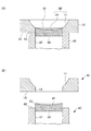
図1は本発明の第1実施形態に係るガラス成形体の製造方法で用いる成形型の断面図であり、図2はこの実施形態に係る方法で用いる別の成形型の断面図である。また、図3は、この実施形態に係るガラス成形体の製造方法の過程を示す図である。
<First Embodiment>
FIG. 1 is a cross-sectional view of a mold used in the method for producing a glass molded body according to the first embodiment of the present invention, and FIG. 2 is a cross-sectional view of another mold used in the method according to this embodiment. Moreover, FIG. 3 is a figure which shows the process of the manufacturing method of the glass forming body which concerns on this embodiment.
図1に示されるように、本実施形態に係るガラス成形型は、ガラス塊が載置される受け面30を有する型母材を備え、この型母材は、受け面30の一部分を構成する面21を含む第1嵌合部20と、この第1嵌合部20を包囲し受け面30の他部分を構成する面11を含む外周部10とを有する。そして、外周部10に第1嵌合部20が着脱可能に嵌合されて、受け面30が形成される。受け面30は一般的に滑らかである必要があるため、面11,21は境界31を介して連続するような形状を有する。
As shown in FIG. 1, the glass mold according to the present embodiment includes a mold base material having a receiving
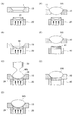
図3に示されるように、面21を含む第1嵌合部20を、面11を含む外周部10に嵌合して受け面30を形成し(A〜B)、この受け面30に供給管50から溶融ガラスMGを供給し、受け面30の上で溶融ガラス塊GGを形成する(C〜D)。この過程で溶融ガラス塊に凹凸が生じやすいのは、面11,21の境界31である。従って、凹凸が機能面に生じないように、境界31を、溶融ガラス塊GGのうちガラス成形体GMの機能面にならない部分に対向させることが好ましい。
As shown in FIG. 3, the
ガラス成形体GMの機能面になる部分は、適宜選択されるが、一般的には中央を含む部分であることが多い。従って、ガラス成形型の汎用性を向上する観点では、境界31が外方に位置することが好ましい。ただし、境界31が中央又はその近傍に位置していてもよい。また、境界31が過度に外方に位置すると、後述の溶融ガラス塊の配置工程において、外周部10に支持される溶融ガラス塊が変形しやすい点も考慮することが望ましい。
Although the part used as the functional surface of the glass molded object GM is selected suitably, generally it is a part including a center in many cases. Therefore, it is preferable that the
本実施形態において、面21を有する面形成体24が外周部10の中空部分に挿入される。ここで、面形成体24の側部23が、外周部10の中空部分の内壁13と略対称な形状を有しているため、第1嵌合部20が外周部10に着脱可能に嵌合される。側部23及び内壁13の断面形状は、特に限定されず、円、楕円、矩形等であってよいが、溶融ガラス塊に対して対称である点で、円であることが好ましい。
In the present embodiment, the
本実施形態のように、面形成体24の外周に鍔部25が設けられていることが好ましい。面形成体24を外周部10の中空部分に挿入していくと、やがて鍔部25が下面15に係止されて挿入が制止されるため、面11,21の位置関係を一定にすることができる。従って、鍔部25を、下面15に係止された時点で面11,21が滑らかに連続するように設計することで、滑らかな受け面30を確実に形成することができる。なお、鍔部25の具体的な構造は、下面15に係止されて面形成体24の挿入を制止し得るものであれば、特に限定されない。
Like this embodiment, it is preferable that the
また、本実施形態のように、面形成体24を多孔質で構成することが好ましい。これにより、面形成体24に気体を供給することで、面21から溶融ガラスMGへと気体を噴出できるので、溶融ガラスMGが面21に付着して、ガラス成形体の品質が低下したり、面21が損傷したりする事態を抑制することができる。なお、面形成体24は、非多孔質であってもよく、また非多孔質に細孔を形成したものでもよい。
In addition, as in the present embodiment, the
図3に示されるように、第1嵌合部20を外周部10から取り外し(E)、外周部10の上の溶融ガラス塊GGを受け面30と異なる成形面の上に配置する。この間、溶融ガラス塊GGは外周部10のみに支持されているため、溶融ガラス塊GGのうち面11に対向する部分には自重によって凹凸が生じやすい一方、面11に対向しない部分(つまり、面21に対向していた部分)には凹凸が生じにくい。従って、この部分をガラス成形体GMの機能面との関係で適宜選択することで、所望形状の機能面を有するガラス成形体GMが製造される。具体的には、溶融ガラス塊を形成する際に、面21を、溶融ガラス塊GGのうちガラス成形体GMの機能面になる部分に対向させることが好ましい。
As shown in FIG. 3, the first
本実施形態では、図3(F)〜(G)に示されるように、第1嵌合部20を取り外した後の外周部10に、成形面30’の一部分を構成する面41を含む第2嵌合部40を嵌合して成形面30’を形成することで、溶融ガラス塊GGを成形面30’の上に配置する。これにより、溶融ガラス塊GGが面11上に位置したまま受け面30から成形面30’へと配置されるため、溶融ガラス塊GGの姿勢の大きい変化が生じにくく、成形時の偏肉等の事態を容易に抑制できる。
In the present embodiment, as shown in FIGS. 3F to 3G, the outer
第2嵌合部40の詳細を図2に示す。外周部10は、成形面30’の一部分を構成する面41を含む第2嵌合部40が着脱可能に嵌合されて、成形面30’を形成する。成形面30’も一般的に滑らかである必要があるため、面11,41は境界31を介して連続するような形状を有する。
The detail of the 2nd
本実施形態において、面41を有する面形成体44が外周部10の中空部分に挿入される。ここで、面形成体44の側部43が、外周部10の中空部分の内壁13と略対称な形状を有しているため、第2嵌合部40が外周部10に着脱可能に嵌合される。側部43の断面形状は、特に限定されず、円、楕円、矩形等であってよいが、溶融ガラス塊に対して対称である点で、円であることが好ましい。
In the present embodiment, the
本実施形態のように、面形成体44の外周に鍔部45が設けられていることが好ましい。面形成体44を外周部10の中空部分に挿入していくと、やがて鍔部45が下面15に係止されて挿入が制止されるため、面11,41の位置関係を一定にすることができる。従って、鍔部45を、下面15に係止された時点で面11,41が滑らかに連続するように設計することで、滑らかな成形面30’を確実に形成することができる。なお、鍔部25の具体的な構造は、下面15に係止されて面形成体24の挿入を制止し得るものであれば、特に限定されない。
Like this embodiment, it is preferable that the
また、本実施形態において、面21,41は、互いに同一又は異なる特性を有してよい。溶融ガラスMGから溶融ガラス塊GGの形成に適した面21、溶融ガラス塊GGからガラス成形体GMの形成に適した面41を独立して用いることで、より高品質のガラス成形体を製造することができる。具体的に、溶融ガラスMGは変形性に優れるため、面21の形状が溶融ガラスMGに転写しても、ガラス成形体GMへの過程で滑らかに戻すことができる。このため、面21は、溶融ガラスMGの付着を抑制することを優先して構成されることが好ましい。他方、溶融ガラス塊GGは変形性が乏しいため、面41の形状が溶融ガラス塊GGの形状を決定しやすい一方、溶融ガラスMGよりも降温されているので、面41に付着しにくい。このため、面41は滑らかであることを優先して構成されることが好ましい。
In the present embodiment, the
例えば、本実施形態では、面形成体44を非多孔質で構成している。これにより、面形成体44がある程度滑らかな形状を有するため、その形状が転写されるガラス成形体GMの表面を滑らかにすることができる。ただし、面形成体24は、多孔質であってもよく、また非多孔質に細孔を形成したものでもよい。
For example, in this embodiment, the
また、本実施形態では、面41が、製造すべきガラス成形体GMに近似した形状を有している。これにより、面41の曲率は、ガラス成形体GMの形状にかかわらず共用し得る面21の曲率とは異なっている。なお、面21,41の形状は図2では凹面であるが、これに限られず、平面や凸面であってもよい。
In the present embodiment, the
本発明は、ガラス塊が載置される載置面を有する型母材を備えるガラス成形型であって、型母材は、載置面の一部分を構成する面を含む嵌合部と、この嵌合部を包囲し載置面の他部分を構成する面を含む外周部とを有し、外周部に嵌合部が着脱可能に嵌合されて、載置面が形成されるガラス成形型を包含する。前述の第1嵌合部20及び第2嵌合部40が嵌合部を構成し、受け面30及び成形面30’が載置面を構成する。
The present invention is a glass molding die including a mold base material having a mounting surface on which a glass lump is placed, and the mold base material includes a fitting portion including a surface constituting a part of the mounting surface, A glass mold that surrounds the fitting portion and includes an outer peripheral portion that includes a surface that constitutes another portion of the mounting surface, and the mounting portion is detachably fitted to the outer peripheral portion to form the mounting surface Is included. The first
また、本発明は、ガラス成形型における嵌合部として用いられるガラス成形型用部品であって、載置面の一部分を構成する面を備え、外周部に着脱可能に嵌合されて載置面を形成するガラス成形型用部品も包含する。前述の第1嵌合部20及び第2嵌合部40は、このガラス成形型用部品を構成する。
Further, the present invention is a glass mold part used as a fitting portion in a glass mold, and includes a surface that constitutes a part of a mounting surface, and is detachably fitted to an outer peripheral portion to be mounted. Also included are glass mold parts that form The first
さらに、本発明は、本発明の方法で製造されたガラス成形体を用いて光学素子を製造する光学素子の製造方法、この製造方法で製造された光学素子を用いて光学機器を製造する光学機器の製造方法も包含する。本発明の方法で製造されたガラス成形体は、高品質でありかつ容易に製造でき安価であり得るため、光学素子の素材として有用である。 Furthermore, the present invention provides an optical element manufacturing method for manufacturing an optical element using the glass molded body manufactured by the method of the present invention, and an optical apparatus for manufacturing an optical apparatus using the optical element manufactured by the manufacturing method. This manufacturing method is also included. The glass molded body produced by the method of the present invention is useful as a material for optical elements because it is of high quality and can be easily produced and inexpensive.
本発明の光学素子の製造方法では、ガラス成形体GMをプレス成型用成形型(図示せず)に移送し、このプレス成型用成形型でプレス成形を行うことで光学素子を製造する。ガラス成形体GMの移送は、外周部10の上にガラス成形体GMを保持した状態で行うことが、設備の簡素化及び移送間のガラス成形体GMの損傷抑制の点で好ましい。ただし、ガラス成形体GMの移送は、これに限られず、別の手段で行ってもよい。
In the method for producing an optical element of the present invention, the glass molded body GM is transferred to a press molding mold (not shown), and the optical element is manufactured by performing press molding with this press molding mold. Transfer of the glass molded body GM is preferably performed in a state where the glass molded body GM is held on the outer
本発明の光学素子の製造方法では、プレス成形後の光学素子を外周部10の上に保持し、機能面が他物体と接触しない状態を維持しながら光学素子を冷却し、梱包する工程を更に有することが好ましい。これにより、梱包までの間、光学素子の特に機能面の損傷を抑制できる。また、光学素子の梱包は、外周部を容器として行うことが好ましい。これにより、外周部から梱包容器への光学素子の移送という工程が省略され、設備の簡素化及び移送間の光学素子の更なる損傷抑制が可能である。
The optical element manufacturing method of the present invention further includes a step of holding the optical element after press molding on the outer
本発明における光学素子は、光学レンズ等のガラス製部材のみからなるものに限定されない。例えば、外周部として鏡筒を用い、ガラス成形体をプレス成形することで製造される、光学レンズが鏡筒に固着した構造の鏡筒付きレンズも、本発明における光学素子に該当する。なお、鏡筒付きレンズの一般的な製造方法は従来周知であるため、説明を省略する(例えば特開2010−102225号公報)。 The optical element in this invention is not limited to what consists only of glass members, such as an optical lens. For example, a lens with a lens barrel having a structure in which an optical lens is fixed to a lens barrel manufactured by press-molding a glass molded body using a lens barrel as an outer peripheral portion also corresponds to the optical element in the present invention. In addition, since the general manufacturing method of the lens with a lens barrel is conventionally well-known, description is abbreviate | omitted (for example, Unexamined-Japanese-Patent No. 2010-102225).
<第2実施形態>
図4は、本発明の第2実施形態に係るガラス成形体の製造方法で用いる成形型の断面図であり、図5は図4の成形型の分割状態を示す断面図である。また、図6は、この実施形態に係るガラス成形体の製造方法の過程を示す図である。本実施形態は、外周部10Aの構造において第1実施形態と異なる。
<Second Embodiment>
FIG. 4 is a cross-sectional view of a mold used in the method for producing a glass molded body according to the second embodiment of the present invention, and FIG. 5 is a cross-sectional view showing a divided state of the mold of FIG. Moreover, FIG. 6 is a figure which shows the process of the manufacturing method of the glass forming body which concerns on this embodiment. This embodiment is different from the first embodiment in the structure of the outer
図4及び5に示されるように、外周部10Aは、2以上の割型10a,10bに分割可能である。割型10a,10bの各々は、分割された割面11a,11b、割内壁13a,13b、割下面15a,15bを有しており、当接面14において合体すると、面11、内壁13、下面15を形成する。
As shown in FIGS. 4 and 5, the outer
図6に示されるように、第1嵌合部20を、割型10a,10bを当接面14において合体させた外周部10Aに嵌合して受け面30を形成し(A〜B)、この受け面30に供給管50から溶融ガラスMGを供給し、受け面30の上で溶融ガラス塊GGを形成する(C〜D)。この過程で溶融ガラス塊に凹凸が生じやすいのは、境界31に加えて当接面14である。
As FIG. 6 shows, the
しかし、溶融ガラス塊GGのうち当接面14と対向する部分は、一般的にはガラス成形体GMにおいて機能面にならない外側部分である。このため、溶融ガラス塊GGに凹凸が生じても問題にはなりにくく、割型10a,10bの合体の精度を過剰に高めなくても足り、精度を向上するための設備を簡素化し得る。また、当接面14を面11の中心を外した位置にする(例えば、特開2009−286679号公報)必要性も小さい。
However, the portion facing the
次に、第1嵌合部20を外周部10Aから取り外し(図6(E))、下型61の下成形面63の上方において外周部10Aを割型10a,10bに分割することで、外周部10A上の溶融ガラス塊GGを下成形面63へと落下させる(図6(F))。そして、溶融ガラス塊GGを、下型61と、上成形面67を有する上型65とを接近させ、押圧することで、ガラス成形体GMへと成形する。
Next, the first
10,10A 外周部
10a,10b 割型
11 面
13 内壁
14 当接面
15 下面
20 第1嵌合部
21 面
23 側部
24 面形成体
25 鍔部
30 受け面
30’ 成形面
31 境界
40 第2嵌合部
41 面
43 側部
44 面形成体
45 鍔部
50 供給管
61 下型
63 下成形面
65 上型
67 上成形面
MG 溶融ガラス
GG 溶融ガラス塊
GM ガラス成形体
10, 10A Outer
Claims (15)
溶融ガラスを受ける受け面の一部分を構成する面を含む第1嵌合部を、前記受け面の他部分を構成する面を含む外周部に嵌合して、前記受け面を形成し、
前記受け面に溶融ガラスを供給し、前記受け面の上で溶融ガラス塊を形成し、
前記第1嵌合部を前記外周部から取り外し、前記外周部の上の溶融ガラス塊を前記受け面と異なる成形面の上に配置し、
前記成形面の上で前記溶融ガラス塊をガラス成形体へと成形する工程を有するガラス成形体の製造方法。 A method for producing a glass molded body, comprising:
A first fitting portion including a surface constituting a part of a receiving surface for receiving molten glass is fitted to an outer peripheral portion including a surface constituting another portion of the receiving surface, thereby forming the receiving surface,
Supplying molten glass to the receiving surface, forming a molten glass lump on the receiving surface;
The first fitting portion is removed from the outer peripheral portion, the molten glass lump on the outer peripheral portion is disposed on a molding surface different from the receiving surface,
The manufacturing method of the glass forming body which has the process of shape | molding the said molten glass lump into a glass forming body on the said shaping | molding surface.
前記成形面の上方において前記外周部を割型に分割することで、前記外周部上の溶融ガラス塊を前記成形面へと落下させる請求項1から3いずれか記載の製造方法。 As the outer peripheral portion, one that can be divided into two or more split molds,
The manufacturing method according to any one of claims 1 to 3, wherein the molten glass lump on the outer peripheral portion is dropped onto the forming surface by dividing the outer peripheral portion into a split mold above the forming surface.
前記型母材は、前記載置面の一部分を構成する面を含む嵌合部と、この嵌合部を包囲し前記載置面の他部分を構成する面を含む外周部とを有し、
前記外周部に前記嵌合部が着脱可能に嵌合されて、前記載置面が形成されるガラス成形型。 A glass molding die comprising a mold base material having a placement surface on which a glass lump is placed,
The mold base material has a fitting portion including a surface constituting a part of the placement surface, and an outer peripheral portion including a surface surrounding the fitting portion and constituting the other portion of the placement surface,
A glass molding die in which the fitting portion is detachably fitted to the outer peripheral portion to form the placement surface.
前記載置面の一部分を構成する面を備え、
前記外周部に着脱可能に嵌合されて前記載置面を形成するガラス成形型用部品。 A glass mold part used as a fitting portion in the glass mold according to any one of claims 12 to 14,
Comprising a surface constituting a part of the mounting surface,
A glass mold part that is detachably fitted to the outer peripheral portion to form the placement surface.
Priority Applications (1)
| Application Number | Priority Date | Filing Date | Title |
|---|---|---|---|
| JP2010228654A JP2012082096A (en) | 2010-10-08 | 2010-10-08 | Method for manufacturing molded glass body, glass molding tool and component for glass molding tool |
Applications Claiming Priority (1)
| Application Number | Priority Date | Filing Date | Title |
|---|---|---|---|
| JP2010228654A JP2012082096A (en) | 2010-10-08 | 2010-10-08 | Method for manufacturing molded glass body, glass molding tool and component for glass molding tool |
Publications (1)
| Publication Number | Publication Date |
|---|---|
| JP2012082096A true JP2012082096A (en) | 2012-04-26 |
Family
ID=46241379
Family Applications (1)
| Application Number | Title | Priority Date | Filing Date |
|---|---|---|---|
| JP2010228654A Pending JP2012082096A (en) | 2010-10-08 | 2010-10-08 | Method for manufacturing molded glass body, glass molding tool and component for glass molding tool |
Country Status (1)
| Country | Link |
|---|---|
| JP (1) | JP2012082096A (en) |
Cited By (1)
| Publication number | Priority date | Publication date | Assignee | Title |
|---|---|---|---|---|
| EP4335605A1 (en) | 2022-08-30 | 2024-03-13 | FUJIFILM Corporation | Method of manufacturing structure |
Citations (16)
| Publication number | Priority date | Publication date | Assignee | Title |
|---|---|---|---|---|
| JPH03137030A (en) * | 1989-10-23 | 1991-06-11 | Minolta Camera Co Ltd | Method and apparatus for molding glass lens |
| JPH03265528A (en) * | 1990-03-15 | 1991-11-26 | Olympus Optical Co Ltd | Method for molding optical element |
| JPH05286728A (en) * | 1992-04-03 | 1993-11-02 | Olympus Optical Co Ltd | Production of glass lens |
| JPH06115957A (en) * | 1991-10-21 | 1994-04-26 | Olympus Optical Co Ltd | Molding device for optical element |
| JPH06340430A (en) * | 1993-05-31 | 1994-12-13 | Canon Inc | Production of optical glass device |
| JPH09124325A (en) * | 1995-10-30 | 1997-05-13 | Olympus Optical Co Ltd | Forming method of optical element |
| JPH11310419A (en) * | 1998-04-30 | 1999-11-09 | Olympus Optical Co Ltd | Glass gob and its production |
| JP2000128550A (en) * | 1998-10-22 | 2000-05-09 | Olympus Optical Co Ltd | Optical element forming die |
| JP2000239024A (en) * | 1999-02-22 | 2000-09-05 | Olympus Optical Co Ltd | Production of material for forming optical element, production of formed optical element, and production apparatus therefor |
| JP2002128535A (en) * | 2000-10-17 | 2002-05-09 | Canon Inc | Forming method of glass gob for optical element |
| JP2003020248A (en) * | 2001-07-03 | 2003-01-24 | Hoya Corp | Method for manufacturing glass formed goods and method for manufacturing glass press formed goods |
| JP2003107317A (en) * | 2001-09-27 | 2003-04-09 | Fuji Photo Optical Co Ltd | Method for manufacturing optical element with lens- barrel |
| JP2004323289A (en) * | 2003-04-24 | 2004-11-18 | Hitachi Maxell Ltd | Lens, lens array and lens module, manufacturing method for lens array and manufacturing apparatus of lens array |
| JP2008169051A (en) * | 2007-01-09 | 2008-07-24 | Alps Electric Co Ltd | Optical lens and production method |
| JP2009007221A (en) * | 2007-06-29 | 2009-01-15 | Olympus Corp | Method for forming optical element |
| JP2010138052A (en) * | 2008-12-15 | 2010-06-24 | Canon Inc | Method of producing preform of optical device |
-
2010
- 2010-10-08 JP JP2010228654A patent/JP2012082096A/en active Pending
Patent Citations (16)
| Publication number | Priority date | Publication date | Assignee | Title |
|---|---|---|---|---|
| JPH03137030A (en) * | 1989-10-23 | 1991-06-11 | Minolta Camera Co Ltd | Method and apparatus for molding glass lens |
| JPH03265528A (en) * | 1990-03-15 | 1991-11-26 | Olympus Optical Co Ltd | Method for molding optical element |
| JPH06115957A (en) * | 1991-10-21 | 1994-04-26 | Olympus Optical Co Ltd | Molding device for optical element |
| JPH05286728A (en) * | 1992-04-03 | 1993-11-02 | Olympus Optical Co Ltd | Production of glass lens |
| JPH06340430A (en) * | 1993-05-31 | 1994-12-13 | Canon Inc | Production of optical glass device |
| JPH09124325A (en) * | 1995-10-30 | 1997-05-13 | Olympus Optical Co Ltd | Forming method of optical element |
| JPH11310419A (en) * | 1998-04-30 | 1999-11-09 | Olympus Optical Co Ltd | Glass gob and its production |
| JP2000128550A (en) * | 1998-10-22 | 2000-05-09 | Olympus Optical Co Ltd | Optical element forming die |
| JP2000239024A (en) * | 1999-02-22 | 2000-09-05 | Olympus Optical Co Ltd | Production of material for forming optical element, production of formed optical element, and production apparatus therefor |
| JP2002128535A (en) * | 2000-10-17 | 2002-05-09 | Canon Inc | Forming method of glass gob for optical element |
| JP2003020248A (en) * | 2001-07-03 | 2003-01-24 | Hoya Corp | Method for manufacturing glass formed goods and method for manufacturing glass press formed goods |
| JP2003107317A (en) * | 2001-09-27 | 2003-04-09 | Fuji Photo Optical Co Ltd | Method for manufacturing optical element with lens- barrel |
| JP2004323289A (en) * | 2003-04-24 | 2004-11-18 | Hitachi Maxell Ltd | Lens, lens array and lens module, manufacturing method for lens array and manufacturing apparatus of lens array |
| JP2008169051A (en) * | 2007-01-09 | 2008-07-24 | Alps Electric Co Ltd | Optical lens and production method |
| JP2009007221A (en) * | 2007-06-29 | 2009-01-15 | Olympus Corp | Method for forming optical element |
| JP2010138052A (en) * | 2008-12-15 | 2010-06-24 | Canon Inc | Method of producing preform of optical device |
Cited By (1)
| Publication number | Priority date | Publication date | Assignee | Title |
|---|---|---|---|---|
| EP4335605A1 (en) | 2022-08-30 | 2024-03-13 | FUJIFILM Corporation | Method of manufacturing structure |
Similar Documents
| Publication | Publication Date | Title |
|---|---|---|
| US20060162385A1 (en) | Press mold and method of manufacturing optical element | |
| CN100555015C (en) | The manufacture method of Unitarily molded lens and retainer | |
| US7966844B2 (en) | Press mold and method of manufacturing optical element | |
| JP2012106895A (en) | Glass optical element and method for manufacturing the same | |
| JP5021205B2 (en) | Mold press mold and optical element manufacturing method | |
| JP2006240913A (en) | Press molding die and press molding method | |
| JP2012082096A (en) | Method for manufacturing molded glass body, glass molding tool and component for glass molding tool | |
| JP2007091586A (en) | Manufacture of optical component part for imaging lens system from melt | |
| JP4460339B2 (en) | Mold press molding apparatus and optical element manufacturing method | |
| JP5654383B2 (en) | Manufacturing method of glass preform for precision press molding and manufacturing method of optical element | |
| JP4558603B2 (en) | Glass container manufacturing apparatus and glass container manufacturing method | |
| JPWO2013118888A1 (en) | GLASS PREFORM MANUFACTURING METHOD, GLASS PREFORM, OPTICAL ELEMENT MANUFACTURING METHOD, AND OPTICAL ELEMENT | |
| JP5345228B2 (en) | Manufacturing method of glass preform for precision press molding and manufacturing method of optical element | |
| JP5121610B2 (en) | Optical element molding method and optical element molding material | |
| JP2003095671A (en) | Plunger and method for molding glassware | |
| JP4792141B2 (en) | Mold press mold and optical element manufacturing method | |
| JP2009046364A (en) | Method for forming optical element and optical element | |
| CN111718107A (en) | 3D glass, manufacturing method thereof, glass cover plate and electronic equipment | |
| JP4473692B2 (en) | Manufacturing method of molded products | |
| JP5489765B2 (en) | Optical element manufacturing method and optical element molding die set | |
| JP2016138037A (en) | Glass gob manufacturing method, glass gob manufacturing apparatus, optical element manufacturing method, and manufacturing method of lens blank for polishing | |
| JP4711697B2 (en) | Optical element manufacturing method, mold press molding apparatus, and positioning apparatus used therefor | |
| JP2011256052A (en) | Mold for molding glass substrate and method for producing glass substrate | |
| US20080209949A1 (en) | Forming device for forming optical glasses | |
| JP2011057515A (en) | Glass gob and method for manufacturing glass molding |
Legal Events
| Date | Code | Title | Description |
|---|---|---|---|
| A621 | Written request for application examination |
Free format text: JAPANESE INTERMEDIATE CODE: A621 Effective date: 20130716 |
|
| A977 | Report on retrieval |
Free format text: JAPANESE INTERMEDIATE CODE: A971007 Effective date: 20131211 |
|
| A131 | Notification of reasons for refusal |
Free format text: JAPANESE INTERMEDIATE CODE: A131 Effective date: 20131224 |
|
| A521 | Written amendment |
Free format text: JAPANESE INTERMEDIATE CODE: A523 Effective date: 20140213 |
|
| A131 | Notification of reasons for refusal |
Free format text: JAPANESE INTERMEDIATE CODE: A131 Effective date: 20140930 |
|
| A521 | Written amendment |
Free format text: JAPANESE INTERMEDIATE CODE: A523 Effective date: 20141114 |
|
| A131 | Notification of reasons for refusal |
Free format text: JAPANESE INTERMEDIATE CODE: A131 Effective date: 20150602 |
|
| A02 | Decision of refusal |
Free format text: JAPANESE INTERMEDIATE CODE: A02 Effective date: 20151027 |